

Page 1

User Guide
For the latest documentation, visit www.escea.com
630160_8
DX-Series / DL-Series
Gas Fireplace
Page 2
If the electrical cord is damaged, it must be replaced by the manufacturer, its service
agent or similarly qualied persons in order to avoid a hazard.
The data label for this appliance, containing technical information and specications,
can be found adhered to the metal work under the burners.
DO NOT PLACE ARTICLES ON OR AGAINST THIS APPLIANCE.
DO NOT USE OR STORE FLAMMABLE MATERIALS NEAR THIS APPLIANCE.
DO NOT SPRAY AEROSOLS IN THE VICINITY OF THIS APPLIANCE WHILST IN OPERATION.
NEVER OPERATE THE FIRE WITH THE FRONT GLASS REMOVED.
IT IS NOT RECOMMENDED TO OPERATE THE FIRE WITH THE FASCIA PANELS REMOVED.
(DL850 only)
THE APPLIANCE MUST BE INSPECTED BEFORE USE AND SERVICED AT LEAST ANNUALLY
BY AN AUTHORISED TECHNICIAN.
THIS APPLIANCE MUST BE INSTALLED IN ACCORDANCE WITH THE MANUFACTURER’S
WRITTEN INSTRUCTIONS.
THIS APPLIANCE IS NOT INTENDED FOR USE BY YOUNG CHILDREN OR INFIRM PERSONS
UNLESS THEY HAVE BEEN ADEQUATELY SUPERVISED BY A RESPONSIBLE PERSON TO
ENSURE THAT THEY CAN USE THE APPLIANCE SAFELY.
YOUNG CHILDREN SHOULD BE SUPERVISED TO ENSURE THAT THEY DO NOT PLAY WITH
THE APPLIANCE.
WARNING
!
Manufactured by: Escea NZ Ltd
17 Carnforth st, PO Box 5277
Dunedin, New Zealand
Email: [email protected]
Web: www.escea.co.nz
Phone: +64 3 478 8220
Distributed in Western
Australia by:
Air Group
28 Division Street
Welshpool, Perth, Western Australia
Web: www.airgroup.com.au
Phone: +61 8 93502200
Distributed in Australia by: Glen Dimplex
1/21 Lionel Road
Waverley, Melbourne
Web: www.glendimplex.com.au
Phone: +61 3 87873500
Page 3

Contents
1. Remote Control Layout 04
2. Basic Operation 05
Initial Start / Battery Placement
Adjusting the Room Temp
Fan Boost
Eect Only
3. Setting the Time 05
4. Keylock 06
5. Timer Operation 06
Activate Timer
De-activate Timer
6. Auxiliary On/O Button 07
7. Over Temp Shuto Operation 07
8. Sound and Smell 08
Sounds
Fan:
Gas Control Valve:
Appliance Metalwork:
Smells:
9. Fascia, Log and Glass care 09
Cleaning the logs / Glass (DL series):
Cleaning the logs / Glass (DX series):
10. Trouble shooting 11
11. Power Failure 13
Page 4
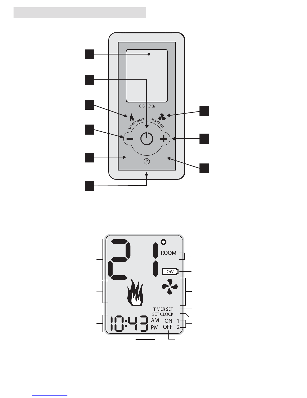
1. Remote Control Layout
C
SET
FAN
BOOST
FLAME
EFFECT
ONLY
Room and Set
temperature
display
Room or Set
temperature indicator
Low battery
indicator
Flame Effect
indicator
Fan Boost indicator
Timer Indicator
Clock adjust indicator
Active timer indicator
Timer On / Off time indicator
Hour and minute
display
Time & timer AM/PM indicator
T
I
M
E
R
S
E
L
E
C
T
A
C
T
I
V
A
T
E
T
I
M
E
R
SETTIME
1
2
3
4
5
6
7
8
9
Display
Shows temperature settings and
status of timers and other functions
On / O
Switches the appliance on and o.
Flame Eect
Places the re in a constant low
output mode.
Minus
Adjusts the temperature and time
settings down. NOTE: The fan will
operate at its lowest settings.
Fan Boost
Puts the fan into a high output mode.
Plus
Adjusts the temperature and time
settings up.
Activate Timer
Enables the timers.
Key Lock
Enables and disables the remotes key lock
3+7
Timer Select
Allows you to program in advance
the times you wish to automatically
turn the re on and o.
Set Time
Allows you to set the clock.
Page 5

2. Basic Operation
− Initial Start / Battery Placement
Remove the battery cover on the rear of the remote. Insert the new “AA” size batteries, being careful of
the polarity. You should now see on the display of the remote the time showing “0:00”. To turn the re
on, press the “POWER” (2) button once, and within a few seconds the appliance will begin its startup
sequence.
NOTE: The appliance begins its startup with a fteen second pre-ignition purge, where the combustion fan runs
on its own before it tries to ignite. Between ignition attempts the remote will alternately show the remote’s “Set”
temperature and a rotating segment indicator to show that the re is in start up mode and will try to ignite
again.
− Adjusting the Room Temp
To set the room temperature, press the ‘plus’ (8) or ‘minus’ (4) buttons repeatedly until the display is showing the desired temperature. The remote will then revert back to the ‘current’ room temperature after 30
seconds. The lowest ame setting will run continuously whilst the medium and high settings will operate
according to the temperature set by the remote.
− Fan Boost
DL-Series ONLY: The re has four FAN SPEED settings. The rst low fan speed will run automatically on
start-up. The second and third fan speed will automatically switch on or o with the increase or decrease
of the set temperature, and the forth fan speed is an optional FAN BOOST speed, which can be accessed
on your remote. Pressing the FAN BOOST button (7) will increase the fan speed to its maximum. When this
mode is not on, the re will still use fan speeds one, two, and three.
DX-Series ONLY: Pressing the FAN BOOST button (7) will make the duct fan increase speed sooner and
maintain its increased airow for longer.
− Eect Only
Pressing the EFFECT ONLY button (3) will only turn on the replaces lowest setting. This mode is intended
as an ambient eect, although some heat will still be produced, and the room air fan will continue to
operate.
NOTE: The room air fan may continue to operate for a few minutes after the re has been switched o to
remove any excess heat.
3. Setting the Time
Press and hold the “SET TIME” button (6) for more than two seconds and this will allow you to set the hour
including “AM” or “PM” using the PLUS (8) or MINUS (4) buttons.
Pressing the “TIME SET” button (6) again will allow you to set the minutes.
Press the button one more time to exit the “SET TIME” mode.
Page 6
4. Keylock
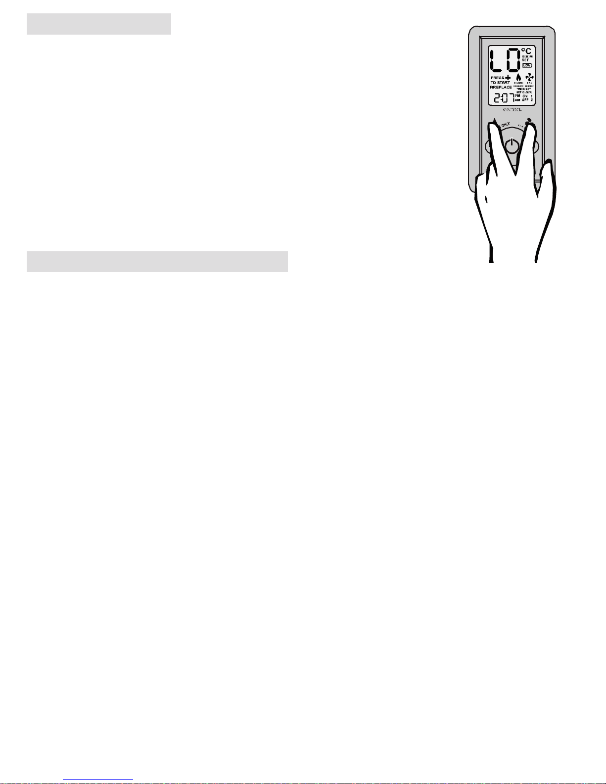
Should you wish to keep the re from being tampered with by children or to discourage people from altering the temperature you can engage a keylock function which
stops the remote buttons from changing any settings. To engage the keylock simply
press the “Flame Eect” and “Fan Boost” buttons (3 + 7) simultaneously until the main
temperature digits display “LO”.
To disengage the keylock again press and hold the “Flame Eect” and “Fan Boost” buttons (3 + 7) simultaneously until the main temperature digits display “UL” and normal
access to the remote functions will be available.
NOTE: The “power” button (2) will still be able to turn the re o. But once turned o no
functions will be available until the keylock has been removed.
5. Timer Operation
Timers are a great way of starting the re when you are not around to turn it on. The timers can be set so
you can wake up or come home to a warm environment.
After pressing the TIMER SELECT button (5) the TIMER SET indicator and the hour gure on the clock will
start ashing. On the bottom right of the display you will also see the word “ON” and the number “1”. This
indicates that you are currently editing the hour that the re will turn “ON” for timer “1”. Pressing the PLUS
(8) or MINUS (4) button will change the hour.
Pressing the TIMER SELECT button (5) again will make the minute gures start ashing. You will continue
to see the “ON” and the number “1”. This indicates that you are currently editing the minute that the re
will turn “ON” for timer “1”. Pressing the PLUS (8) or MINUS (4) button will change the minute.
Pressing the TIMER SELECT button (5) again will make the hour gure start ashing once again. Though
now you will see the “OFF” indicator as well as the number “1”. This indicates that you are currently editing the hour that the re will now turn “OFF” for timer “1”. Pressing the PLUS (8) or MINUS (4) button will
change the hour.
Again pressing the TIMER SELECT button (5) will start the minutes ashing for you to nish editing the
“OFF” time for timer 1.
Pressing the TIMER SELECT button (5) will begin the cycle all over again for timer “2”.
Note: If you do not wish to set timer ‘2’, using the plus or minus keys, navigate to ‘0:FF’ which you will nd between ‘11:00’ and ‘0:00’. Press ‘Timer Select’ (5) again to exit.
− Activate Timer
This option allows you to activate your selected times. Pressing once will activate ‘Timer 1’. Pressing twice
will activate ‘Timer 2’ and by pressing again you will activate them both.
− De-activate Timer
To de-activate the timer, press “Activate Timer” (9) until “TIMER SET” no longer shows on the screen (this
will require between 1 to 3 pushes)
T
I
M
E
R
S
E
L
E
C
T
A
C
T
I
V
A
T
E
T
I
M
E
R
SETTIME
Page 7
6. Auxiliary On/O Button
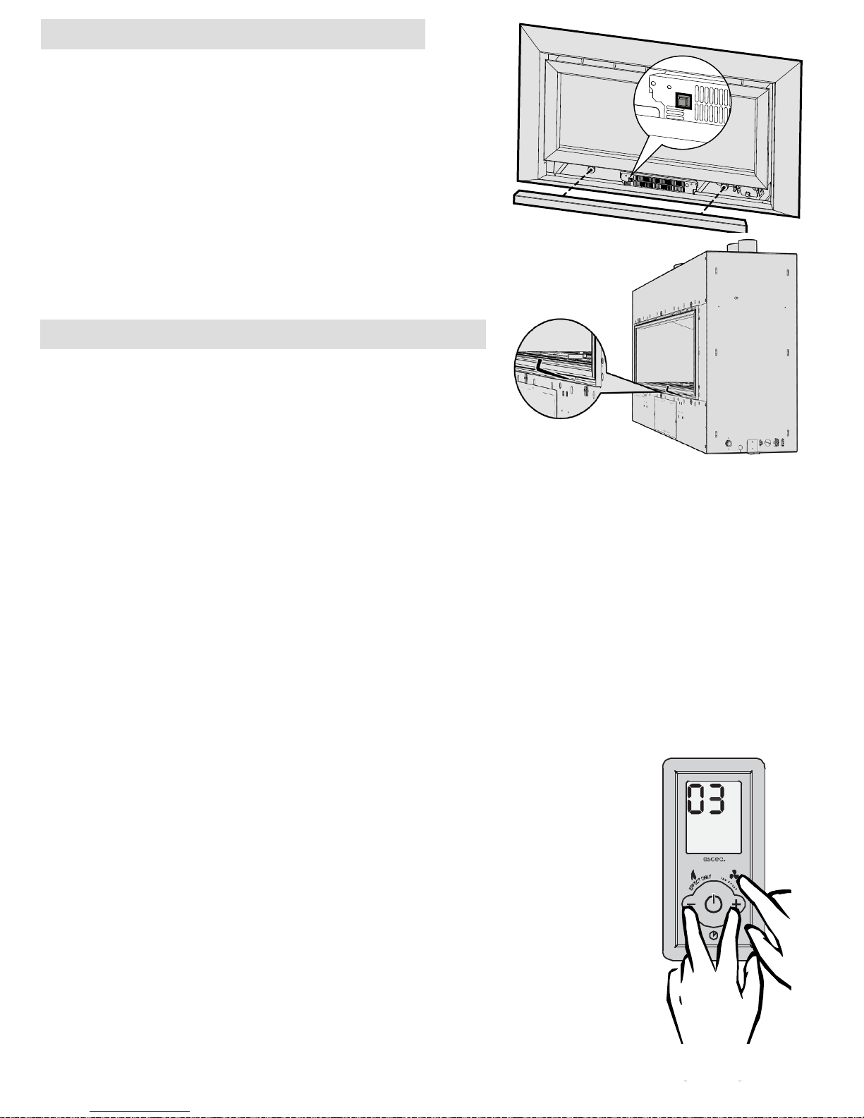
The DL-Series has a manual On/O button located under the
bottom fascia panel as shown.
The DX-Series has a manual On/O button located inside the
re. To access this you will need a long thin tool (such as as allen
key) and insert this through the opening on an angle as shown.
This button should be used if the wireless control becomes lost,
damaged, or its batteries are at. Pushing the “AUX On/O” button once will start the heater and it will run at a medium heat
output setting until the “AUX On/O” is pushed again to shut
the heater down.
7. Over Temp Shuto Operation
By default Escea gas res continue running at their lowest
setting when the “Room” temperature has reached the “Set”
temperature. However, in some cases the output of the re, at
its lowest setting, may exceed that which is needed to keep the
room at a steady temperature and the “Room” temperature may
continue climbing above the “Set” temperature.
Your Escea gas re has a setting where it will turn o the main burner once the “Room” temperature
exceeds the “Set” temperature, leaving only the pilot lit. The main burner will re-light when the “Room”
temperature falls back below the “Set” temperature. This is referred to as the “Overtemp Shut O Mode”.
To enable “Overtemp Shut O Mode”, so the re will turn o the main burner when the “Room” temperature climbs above the “Set” temperature, you need to follow the steps below to make the adjustment to
your Escea remote.
Step1: While the remote is in its “OFF” mode with only the time showing on the display, press the
MINUS (4), PLUS (8) and FAN BOOST (7) buttons simultaneously (as shown below right) until the
characters “03” light up on the display. Release the buttons and the remote will count down and
display “GO”. The screen will then display all characters. This will put the remote into test mode
and the two big temperature digits should begin counting from 0 to
99 repeatedly.
Step 2: Press the “TIMER SELECT” Button (5) and you will see that the
temperature digits stop counting and will momentarily display “ON” to
conrm the setting has been made.
Step 3: To exit the test mode press the ON/OFF button (2).
To turn OFF the “Over Temp Shut O Mode”, so the burners remain lit
when the “Room” temp reaches and goes above the “Set” temp, repeat
step 1.
Step 2: Press the “ACTIVATE TIMER” (9) Button and you will see that the
temperature digits stop counting and will momentarily display “OF” to
conrm the setting has been made.
Step 3: To exit the test mode press the ON/OFF button (2).
T
I
M
E
R
S
E
L
E
C
T
A
C
T
I
V
A
T
E
T
I
M
E
R
SETTIME
DL-Series
DX-Series
Page 8

8. Sound and Smell
Note: Each time the re is lit from cold the glass will fog up with condensation. This is normal and the condensation will disappear within a few minutes once the glass heats up.
− Sounds
It is possible that you will hear some sounds from your gas appliance. This is perfectly normal due to the
fact that there are various types of materials used within your appliance. Listed below are some examples.
These are all normal operating sounds and should not be considered as defects in your appliance.
− Fan:
Escea gas appliances use electric fans to push heated air further into the room. It is not unusual for the fan
to make a “whirring” sound when ON. This sound will increase or decrease in volume depending on the
thermostatic settings.
− Gas Control Valve:
As the gas control valves turn ON and OFF, a dull clicking sound may be audible. These sounds are part
of the normal operation of the re. When the re is switched o after being run for a while, there may be
popping and uttering noises as the residual gas in the burner burns away. These are normal and should
be no cause for concern.
− Appliance Metalwork:
Dierent types and thicknesses of steel will expand and contract at dierent rates resulting in some
“creaking” and “ticking” sounds being heard throughout the heating and cool down cycles.
− Smells:
The rst few times the unit is operated after installation, the unit may release an odour and the ames will
appear orange caused by the curing of the paint, the burning o of the starch in the ceramic logs and the
oils in the metal. This is a temporary curing process which will disappear with use. A deposit on the inside
of the glass, caused by the starch in the logs may appear as a build up after several uses. If this lm is not
removed, it will bake on and may become dicult to remove. When the glass is cold, remove it (see following page) and clean the inside with a non-abrasive cleaner.
WARNING: DO NOT ATTEMPT TO CLEAN THE GLASS WHILE IT IS HOT. NEVER OPERATE THE UNIT WITH
THE GLASS REMOVED.
Page 9
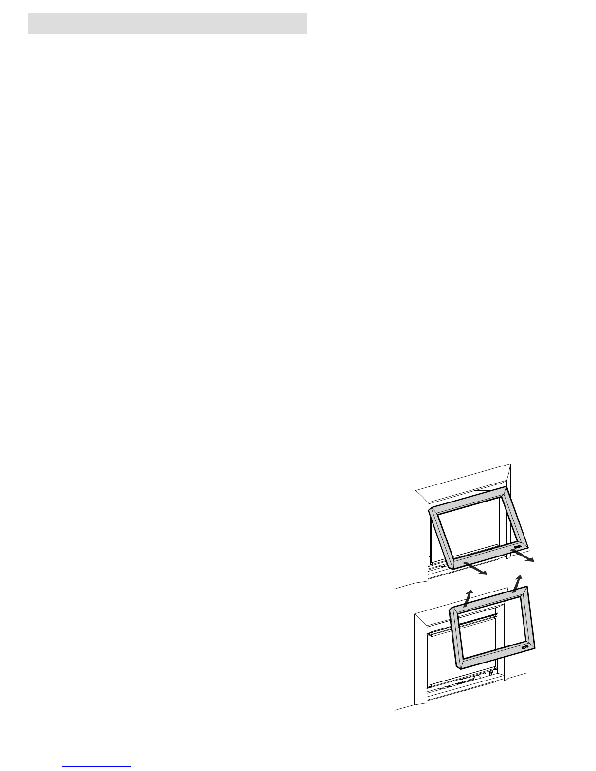
9. Fascia, Log and Glass care
The Fascia is the visible surround of your Escea Gas Fireplace and must be treated carefully to prevent
unsightly marks from tarnishing the visual quality of the product. Some marking over time is inevitable
however, so the following directions will assist you in getting the maximum enjoyment from your Escea
Gas Fireplace.
NEVER, EVER RUB THE FASCIA.
The outside of an Escea Fascia must only be cleaned with a soft microbre cloth. If heavier cleaning is required for the likes of grease or stubborn ngerprint removal we recommend the use of Steel Kleen brand
Ezi Wipes. These wipes have been tested by Escea technicians and produce very satisfying results, when
used correctly. Instructions for their use follow.
For Powder Coated Fascias:
1. Ensure that the Gas Fireplace is o, and that the fascia is cold to the touch.
2. Using the gloves provided with your fascia, remove the towelette from the sachet and wipe the
fascia with even, straight strokes.
3. Because the wipe leaves a protective lm over the fascia, the entire fascia will need to be wiped
to avoid seeing a dierence in surface texture. Ensure this lm is distributed evenly.
4. If the lm is applied too heavily and is quite visible, you can remove the excess by gently wiping
dry with a microbre cloth
5. Ensure that no lm is applied to the glass of your Escea Gas Fireplace. If applied accidentally,
wipe o with an absorbent microbre cloth.
Cleaning the logs / Glass (DL series):
Step 1: If using a Velo or Rado fascia, Remove the lower trim which is
held in place by magnets
Step 2: Lift o the inner fascia by unscrewing the base of the inner
fascia, then pulling it out and lifting it up and o.
Step 3: Unscrew the top and side glass retainers and remove them.
Take care that the glass does not fall forwards at this stage.
Step 4: Lift out glass and place it carefully aside.
Step 5: Take out log set and gently brush any soot from log with a
soft hearth brush. The burner tops can be vacuumed too.
Step 6: Clean the inside and outside of glass with normal glass
cleaning products. Use a clean dry cloth only. Stubborn marks
may be cleaned with a ceramic glass cleaner.
Step 7 : Replace in opposite order and test run heater.
Step 2
Page 10
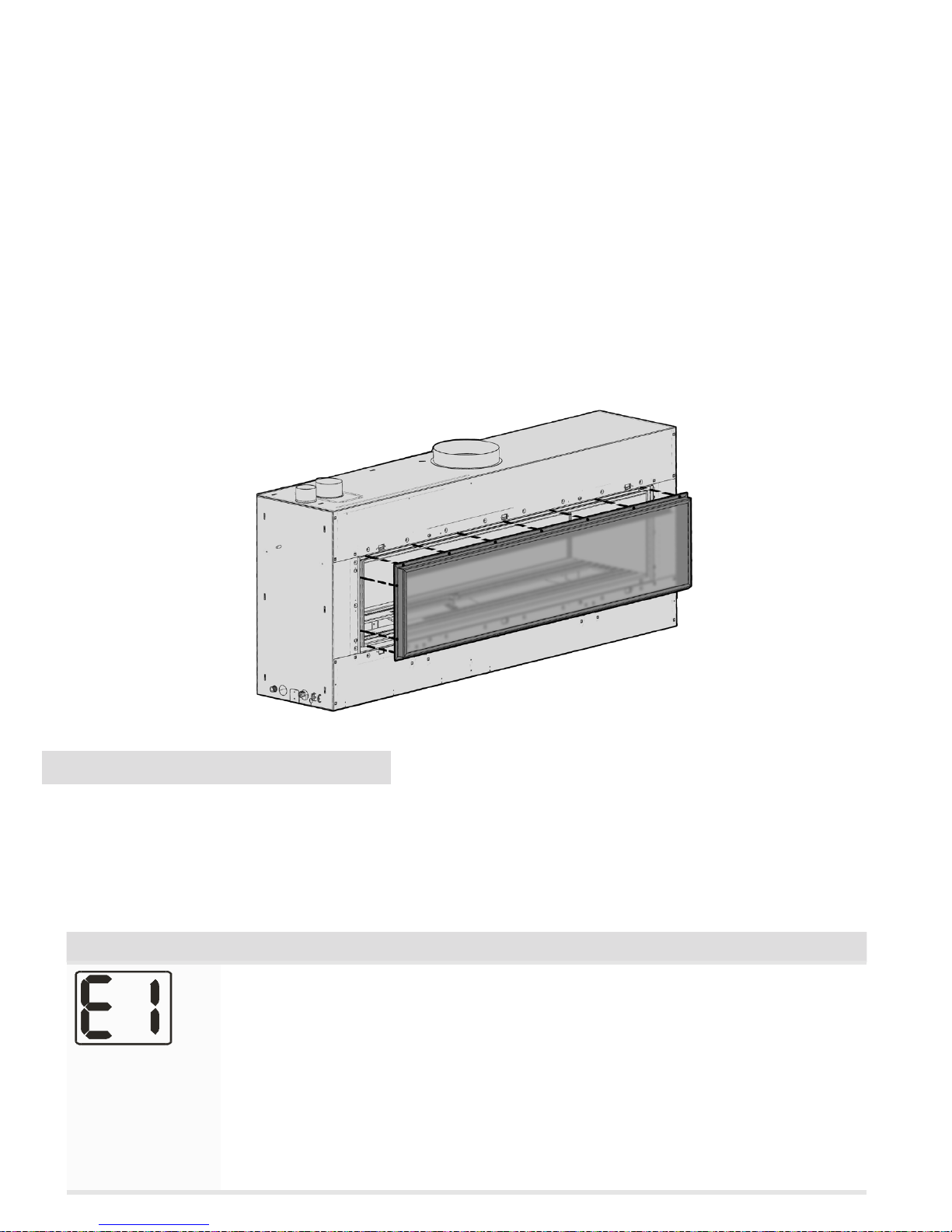
Cleaning the logs / Glass (DX series):
Step 1: If the replace has a fascia, it is recommended that you remove it rst by simply pulling it
towards you evenly, using protective gloves to protect the paint nish. The clips holding it in place will
release.
Step 2: Unscrew all of the fasteners holding the glass in place as shown below using a 3mm allen key
and carefully pull the glass and frame towards you, ensuring you hold onto the glass aswell as the metal
surround frame.
Step 3: Take out log set (if there is one) and gently brush any soot from log with a soft hearth brush. The
burner tops can be vacuumed too.
Step 4: Clean the inside and outside of glass with normal glass cleaning products. Use a clean dry cloth
only. Stubborn marks may be cleaned with a ceramic glass cleaner.
Step 5: Replace in opposite order and test run heater.
10. Trouble shooting
Escea gas res communicate both to and from the re and remote. This enables the remote to provide
some basic fault nding information that is useful in diagnosing faults with your gas supply or ue.
NOTE: The remote will take a minute or two to receive and display the error from the re. Pressing the plus or
minus keys will update the remote
Error Code Suggestion action
Electronics Over
Temp
• Excess lint and dust build-up on the front of the controller tray.
• Possibly fascia panels installed incorrectly resulting in restricted air ow.
• Room air fans may be slowed or stalled. Remove rebox, check that fans are
plugged in, cleaned, and free turning
• (DX only) check that the duct fan is not reversed and blowing “into” the replace instead of out from the replace
Note: This error has a permanent lock out and will require the unit to be reset
after the initial error (turning the power to the re o “at the wall” then on again
after a few seconds).
Page 11
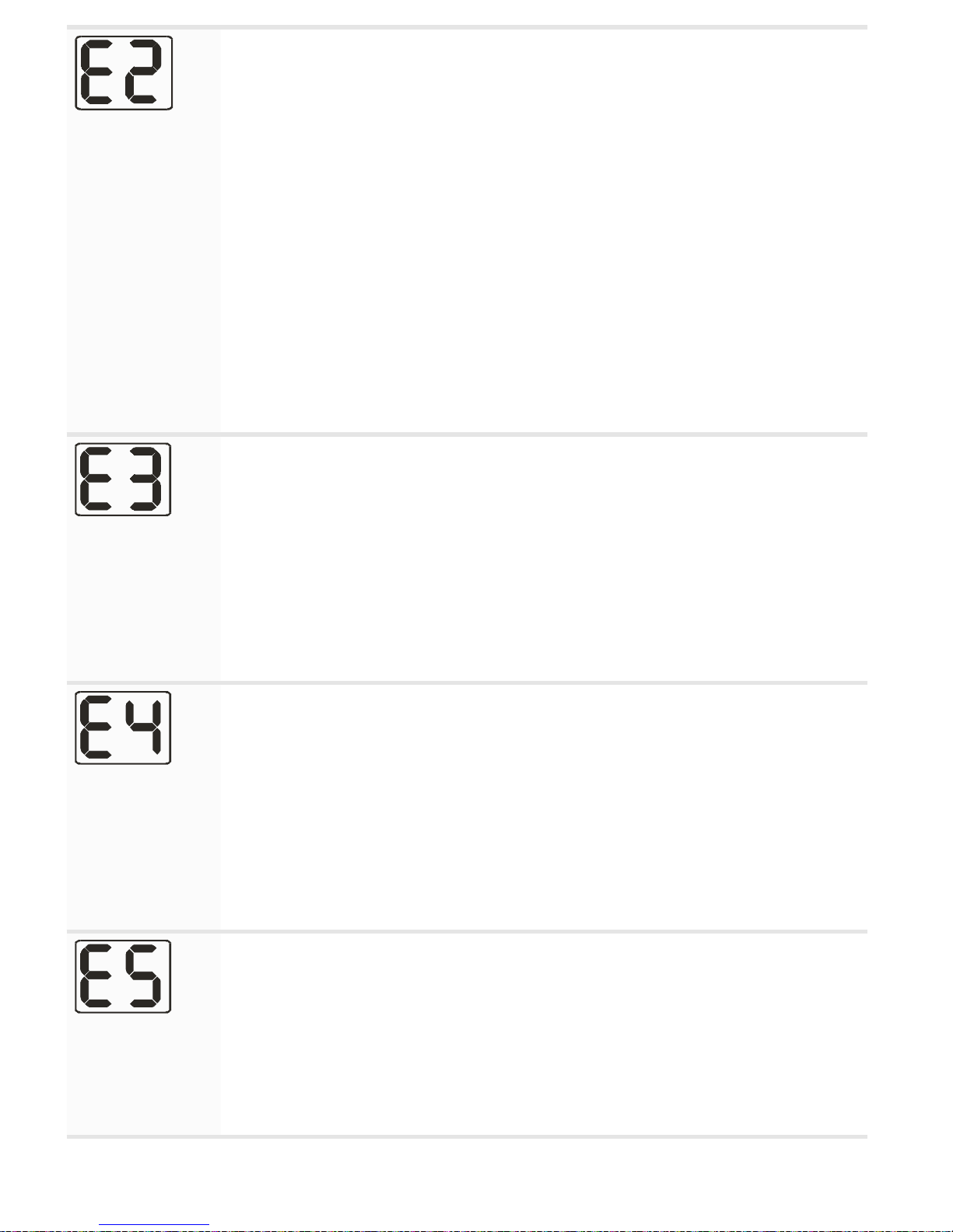
Flame Failure or
Power Flue trip
The re has tried to light three times and failed.
• Check gas supply and check other gas appliances to see if they are aected.
If you have two separate gas cylinders, switch over to the full bottle or
contact your gas supplier. You may need to retry igniting the re a few times
after re-establishing gas supply.
• Check correct gas pressure to the appliance with all other appliances running
• Check the electrode placement in relation to the pilot ame. Ensure it is well
enveloped in ame as per the diagram in the installation instructions. Ensure
no small coals have dropped onto the ignition electrodes between the burners.
• Ensure the electrode is not contacting any metalwork including the burners
and has the correct air gap.
• Check that the electrical power cable between the appliance and the powerue wall terminal is connected and not damaged
• Check that the fan inside the powerue wall terminal is running during
startup. This fan may need servicing if it is slowed or stalled.
Appliance Over
Temperature
Sensor Trip
The bimetallic snap disk mounted on the spigot seal plate at the rear of the re
has tripped. The possible causes for this could include:
• Possibly fascia panels installed incorrectly resulting in restricted air ow at
the top of the re.
• Room air fans may be slowed or stalled. Remove rebox, check that fans are
plugged in, cleaned, and free turning
• The gas regulator being set too high resulting in excess heat build-up.
• The inlet ue not being connected and the appliance drawing warm air from
the cavity. Check ues are securely connected at both ends.
Valve Solenoid
Check Failure
The valve solenoids have failed the pre-ignition test. This is to detect a faulty
valve solenoid. However, it is possible a wire has dislodged.
• Check that the connections to each solenoid are secure and in place. It may
be that the connections on the ends of the wires need to be tightened a
little (e.g. with a pair of pliers) to ensure a robust connection to the valve
terminal.
• Disconnect and reconnect the rebox connectors ensuring they are rmly
pushed into place.
• It could also be that one of the solenoids on the valve inside the re has
failed. If this is the case the valve will need to be replaced.
Remote Cannot
communicate
with re
The remote cannot communicate with the re. Reasons for this could include:
• The re being turned o “at the wall” i.e. a loss of power to the re or the
remote is outside of its eective radio frequency range (too far away from
the re). Typical remote range is 1m to 12m.
• Ensure there is power to the re by pressing the auxiliary on/o (red) button
on the re, then press the on/o button on the remote to clear the error.
Page 12
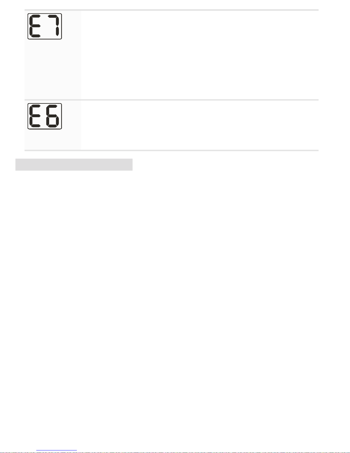
Combustion Air
Flow Error
• Check whether the pressure switch is activating at startup (there is an
orange indicator LED in the control tray). If not check the pressure switch
electrical connection is correct.
• Check that the hoses are connected at both ends. Ensure the hoses are not
kinked.
• Ensure the pressure switch is mounted vertically and the diaphragm is operational. The grey hose should be connect to the low pressure port and the
translucent to the high pressure port
• Check that both ues are securely connected at both ends to the appliance
and the powerue wall terminal and that the ue is not damaged
(DX Only) Duct
Overtemp
The hot air duct temperature sensor has detected excessive heat at the duct
outlet.
• Ensure that there are at least TWO air vents installed and open in the same
room as the replace
• Ensure the duct fan is operating when the replace is running. If not check
that the duct fan cord is plugged into the replace.
11. Power Failure
In the event of power failure the re will immediately shutdown and the gas valves will automatically
close. If the remote was turned o after the power cut then the re will return to standby mode once the
electrical supply is restored until its next use. If however the remote was left in the on mode then the re
will relight within a few minutes of the electrical supply being restored.
 Loading...