

Page 1

Installation / Service Guide
DX1000 / DX1500
For the latest documentation, visit www.escea.com
Gas Fireplaces
630228_18
Page 2

Important:
The appliance shall be installed in accordance with;
• This installation instruction booklet
• Local gas tting regulations
• Municipal building codes
• Electrical wiring regulations
• Any other relevant statutory regulations.
• AS/NZS 5601.1 Gas Installations
This appliance is not intended for use by young children or inrm persons unless they
have been adequately supervised by a responsible person to ensure that they can use the
appliance safely.
Young children should be supervised to ensure that they do not play with the appliance.
Manufactured by: Escea Ltd, PO Box 5277 Dunedin NZ, Ph: +64 3 478 8220
For contact details of your local Escea distributor or dealer please visit:
www.escea.com [email protected]
WARNING:
Failure to follow these instructions could cause a malfunction of this appliance, which
could result in death, serious bodily injury, and/or property damage. Failure to follow
these instructions may also void your re insurance and/or warranty.
This appliance must not be modied.
THIS APPLIANCE MUST BE FITTED WITH AN ESCEA REMOTE ROOM AIR FAN
AND SUITABLE RETURN AIR VENTILATION
THIS APPLIANCE MUST BE FITTED WITH AN ESCEA REMOTE FLUE FAN
THE TERMINAL MUST ALWAYS VENT DIRECTLY OUTDOORS
Who can install this product:
Installation must be carried out by a qualied and registered installer who, on completion
of the installation, must issue a:
AUS: Certicate of Compliance
NZ: Energy Work Certicate
in accordance with national and/or local codes. If these are not issued then the Escea warranty may be void.
Page 3

Warranty Repair and Annual Servicing:
Warranty repair work must be carried out by a recognised Escea gas replace technician.
It is recommended that recognised Escea Gas Fireplace Technicians are also used to carry
out annual servicing requirements (particularly during the warranty period). For contact
details of authorised Escea Gas Fireplace Technicians in your area, please contact the
retailer from whom the appliance was purchased.
General installation information:
This appliance must be installed according to these instructions and in compliance with
all relevant building, gas tting, electrical and other statutory regulations (eg. AS/NZS
5601.1). Any shortcomings in the appliance and ue installation will be the responsibility
of the installer, and Escea will not be accountable for any such failings or their consequences.
Once this appliance is installed it cannot be removed without disturbing the wall lining.
This DX Series replaces has been dispatched from the factory set as a single sided version. This can be converted into a double sided appliance by using the Double Sided
Conversion Kit available from your Escea distributor. Conversion details are shown in
Section E.
An electrician is required to install a 3pin power socket – Section C
Page 4

A Installation Process and Product Description 6
A1 Recommended Installation Process: 6
A2 Product Description 6
A3 Product Dimensions 7
B Creating the Cavity 8
B1 Cavity Shape 8
B2 Designing the Cavity 8
B3 Flue Conguration (For less than 4m length) 9
B4 Flue Conguration (For more than 4m length) 10
B5 Framing Dimensions 11
B6 Cavity Base 11
B7 Hearth 11
B8 Wall Linings 11
B9 Fascia 12
B10 Mantle Clearance 12
B11 Television Clearances 12
B12 Ducting 13
B13 Duct Fan mounting 14
C Installing the Electricity and Gas to the Appliance 15
C1 Power Supply 15
C2 Network Cable 15
C3 Gas Pipe Sizing 16
C4 Gas Pipe Position 16
C5 Gas Isolating Valve 16
D Installing the Flue 17
D1 Installing the Horizontal Powerue Wall Terminal option 17
D2 Installing the Internal Vertical Powerue (Duravent) 18
D3 Installing the Universal Vertical Powerue (Internal Install) 19
D4 Installing an External Vertical Powerue (EVP or UVP) 21
D5 Removing the restrictor plate (EVP, UVP External/Internal) 22
D6 Installing in Accordance with Relevant Codes 23
D7 Creating the Hole in the Outside Wall 24
D8 How to ash the Horizontal Powerue 25
D9 How to ash the Vertical Powerue 25
D10 Running the Flue 26
Page 5

D11 Running the Powerue Electrical Cable 26
E Installing the Appliance 27
E1 Double Sided conversion 27
E2 Installing the Appliance 28
E3 Connecting the Flue 28
E4 Connecting the Network Cable 28
E5 Removing (and replacing) the Glass 29
E6 Remove the Fuelbed Tray & Burners 29
E7 Gas Type Conversion 30
E8 Checking the Gas Operating Pressure 32
E9 Operating the Appliance 34
E10 Auxillary On/O button 35
E11 Home Automation Setup 35
E12 Reinserting fuel bed and ceramic glass 36
F Finishing the Installation 37
F1 Crystalite, Coal, or Driftwood Fuel Bed Installation 37
F2 Log and cone Fuel Bed (Woodland Selection) 37
F3 Wall lining 38
F4 Fitting the Fascia Panels 39
F5 Locating Wall Mount Cradle for Wireless Control 40
F6 Operating the Appliance 40
F7 Normal Operating Sounds and Smells 42
G Installation Checklist 43
S Service Manual 44
S1 Annual service procedure 44
S2 Error Codes 45
S3 Cleaning the Fuel bed and Glass 47
S4 Checking Operating Pressure 48
S5 Replacing a Remote Control 49
S6 Replacing the burners 50
S7 Accessing the control tray 51
S8 Removing the Circuit Board 51
S9 Servicing the Horizontal / Vertical Powerue 53
S10 Wiring Diagram 54
Page 6
A
Installation Process and Product Description
A C D E F G SERVICE
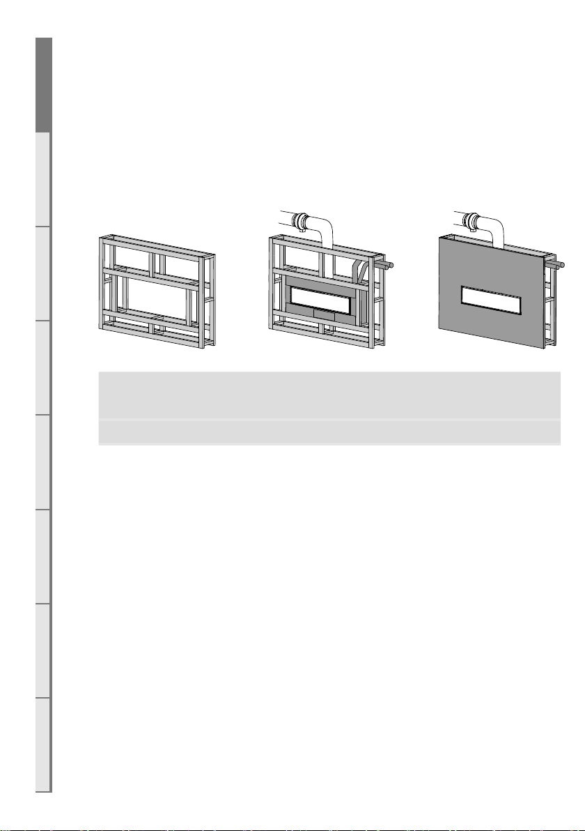
A1 Recommended Installation Process:
The following diagram illustrates the steps required to install your gas re, and the trades
required at each stage.
The sequence in which you choose to do these tasks will vary depending on your indi-
B
vidual installation. Please read these instructions carefully before proceeding with the
installation. Leave the installation of the optional fascia panels until the very end of the
installation and commissioning to avoid damage to the fascia panels.
Create the Cavity Install electrical / gas
connections, ue system, and
replace
Section B Section C, D Section F
Finish installation and t
fascia
A2 Product Description
The Escea DX1500 / DX1000 gas re is a direct vent (fan draught balanced ue), room
sealed gas appliance designed to be built into a cavity. This appliance is ued using a colinear exible aluminium ue connected to a powerue terminal.
The hot air from the gas re is transferred to the room via 250mm ID / 300 mm OD
ducting.
The user will control their re with the Radio Frequency (RF) remote that will normally be
left in its wall mount cradle. In addition to the RF remote it has a single auxiliary On/O
button on the unit. When not in operation it is in a standby mode unless it is physically
isolated from the mains supply.
To access the product Dataplate, rst remove the replace glass, any fuelbed media, the
burners and the rebox base. An access panel is located to the side of the bottom of the
rebox, the dataplate is located underneath this access panel.
6
Page 7
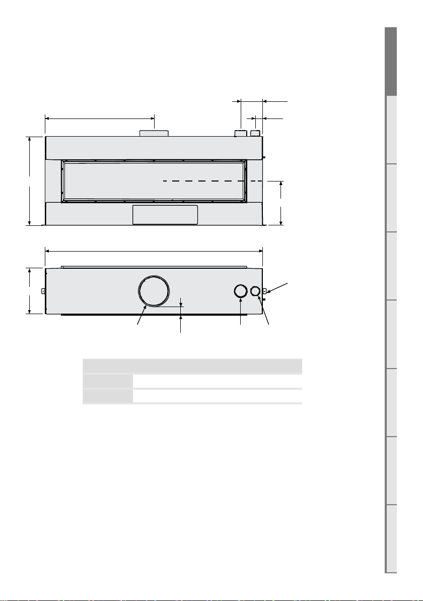
A3 Product Dimensions
183
NOT TO BE MISTAKEN FOR CAVITY DIMENSIONS
All dimensions are in mm
A
744
B
382
Ø250
70 Ø100
ACDEFGSERVICE
61
B
372
Gas, Power, Internet
Connections
Ø75
For more detail, view architectural drawings at www.escea.com
DX1000 DX1500
A 664mm 914mm
B 1328mm 1828mm
7
Page 8
B
Creating the Cavity
A C D E F G SERVICE
B1 Cavity Shape
The DX1500 / DX1000 is suitable for timber framed cavities.
Most existing masonry cavities will not be suitable.
The cavity design & shape will be dependent on a number of things:
B2 Designing the Cavity
B
The following aspects must be considered when designing this installation:
• Appliance physical size
• Single sided or Double sided
• Wall nishing and interaction with appliance
• Positioning of appliance in regards to wall lining (depth into wall)
• Is a Fascia to be used? one side or two sides?
• Exhaust cowl aspect – horizontal / vertical and ue conguration
• Flue exhaust fan noise
• Exhaust cowl access for maintenance
• Duct layout and cavity spaces to run ducting
• Duct fan position
• Access to duct fan for maintenance
• Gas pipe layout
• Gas isolation valve / pressure test point position
• Electrical isolation switch
• Home automation network connections - Ethernet cable layout
□
This DX1500 / DX1000 re is to be installed prior to any wall lining.
The wall lining is the very last task to be completed in this installation.
The cavity and wall linings may be constructed from standard timber framing materials
and do not need to be non-combustible.
Do not line the top of the cavity.
It is not necessary to line the sides, or back of the cavity.
8
Page 9
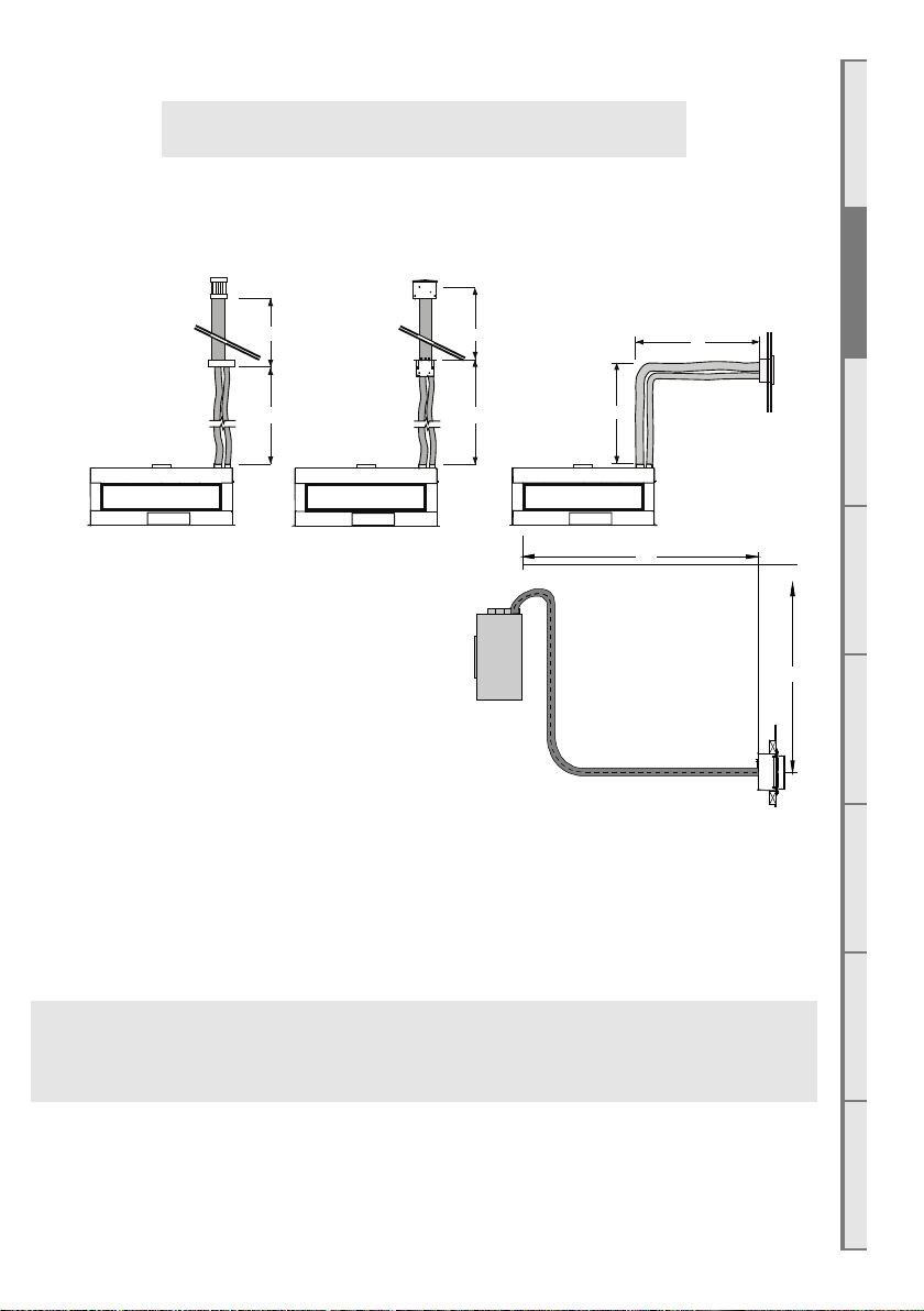
B3 Flue Conguration (For less than 4m length)
X
Y
X + Y = 4m MAX
= 0.6m MIN
4m MAX
1.2m Co-axial Flue
Vertical PowerFlue
Cowl (Duravent)
4m MAX
1.2m F-F Liner
UVP-Internal Cowl
ONLY USE ESCEA APPROVED FLUE COMPONENTS
If your ue system is less than 4m long (as shown in the diagrams below), then a simple
exible ue is required. if you wish to install a longer ue run, up to 12m, see section B4.
X
Note: You must provide sucient access to the
powerue to enable it to be serviced in the
future.
This means that the fan unit must have sufcient
access to allow it to be replaced if necessary.
Y Maximum = 1.5m
Y Minimum = 0m
X Maximum = 4m
X Minimum = 0m
X + Y Maximum = 4m
X + Y Minimum = 0.6m
The ue must be securely xed and adequately supported by brackets fastened to the
building structure at suitable points to ensure
the stability of the ue system.
Any joints within the ue system must be sealed adequately, with a sealing agent used
if necessary. The ue system for the DX1500 / DX1000 is zero rated, so no spaces are
required between the ue and any timber framing.
ACDEFGSERVICE
B
Y
Horizontal Flue option
Minimum: 600mm ue length
Maximum: Total ue length 4m
Note: All sections of horizontal ue if exible must be sloped back toward the re at
□
a rate of no less than 20mm per metre, to allow any condensation to run back into
the appliance.
Vertical Flue option
Minimum: 600mm ue length
Maximum: Total ue length 5.2m
For ue installation, see section D
9
Page 10
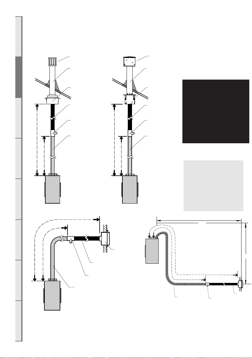
B4 Flue Conguration (For more than 4m length)
X
Condensate Trap
A C D E F G SERVICE
B
If your ue system is greater than 4m long (as shown in diagrams below), then a exible
ue with condensate trap and rigid PolyPro tube ue lengths is required. (For less than
4m ue runs, see section B3)
Vertical PowerFlue
Cowl (Duravent)
1.2m Co-axial Flue
(Duravent)
Vertical Powerue
Enclosure
Ø80mm / Ø100mm
PP Tube
Ø100mm
12m MAX
4m
Condensate Trap
Ø80mm / Ø100mm
Flexible Flue
12m MAX
4m
UVP Cowl
1.2m F-F Liner
UVP Fan Unit
Ø80mm / Ø100mm
PP Tube
Ø100mm
Condensate Trap
Ø80mm / Ø100mm
Flexible Flue
FOR MORE INFORMATION ON
INSTALLATION OF THE POLYPRO FLUE,
SEE ‘POLY PRO FLUE INSTALLATION
INSTRUCTIONS’ AVAILABLE ON:
WWW.ESCEA.COM
OR SUPPLIED WITH THE FLUE.
FOR POLY PRO COMPONENT GUIDES,
THESE ARE AVAILABLE ON:
WWW.ESCEA.COM
HORIZONTAL FLUE COMPONENT GUIDE
VERTICAL FLUE COMPONENT GUIDE
TITLED:
&
Note: All sections of
horizontal ue, if exible,
must be sloped back
toward the re at a rate
of no less than 20mm
per metre, to allow any
condensation to run back
into the appliance.
12m MAX
4m
Y Maximum = 1.5m
Y Minimum = 0m
X Maximum = 12m
ESCEA WALL
TERMINAL
Ø80mm / Ø100mm
Ø80mm / Ø100mm
Flexible Flue
10
PP Tube
Ø100mm
Condensate Trap
Ø80mm / Ø100mm
Flexible Flue
X Minimum = 0m
X + Y Maximum = 12m
X + Y Minimum = 0.6m
4m
12m MAX
Ø100mm
Y
Ø80mm /
Ø100mm
PP Tube
Page 11
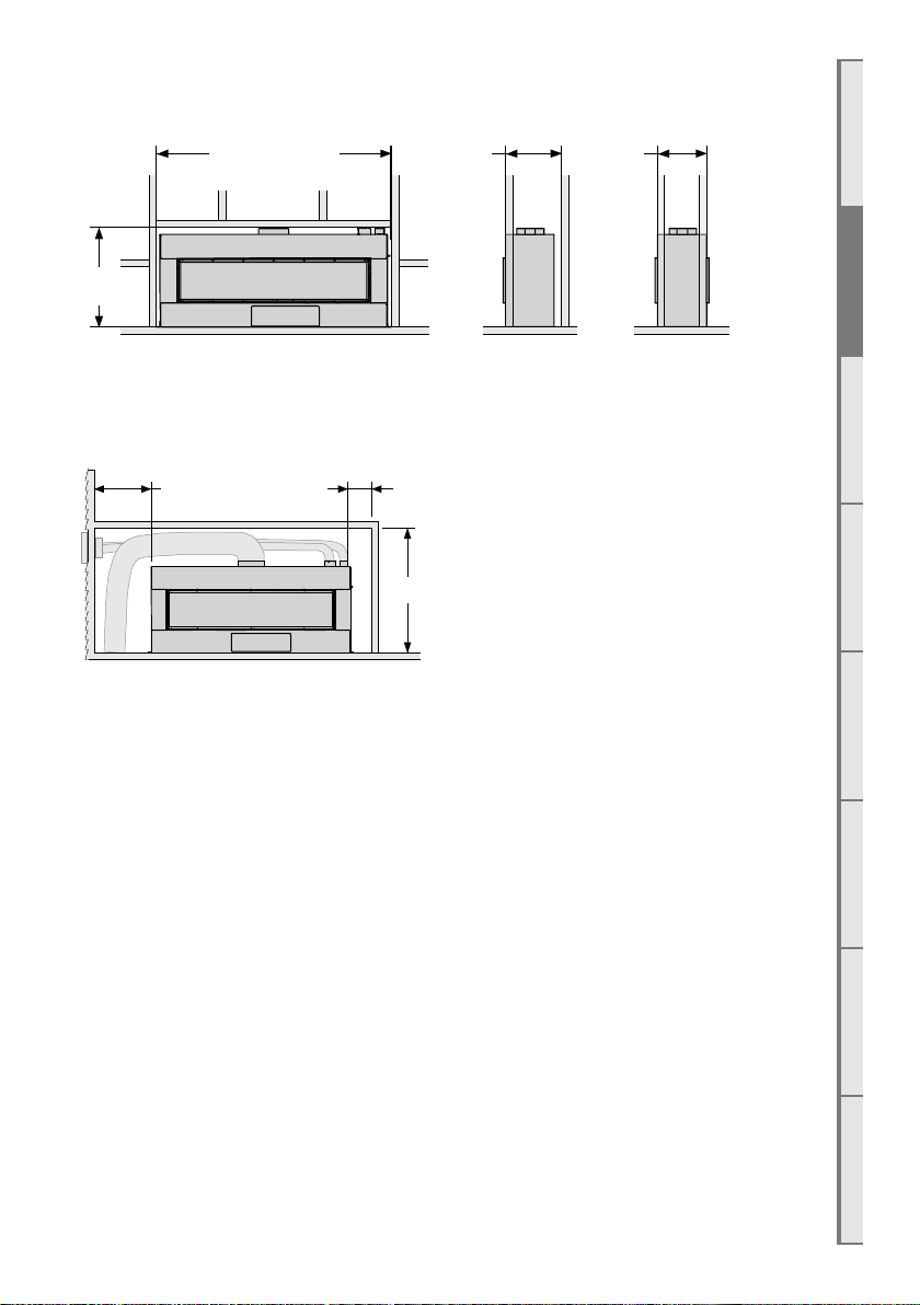
B5 Framing Dimensions
800
1400
1150
MIN
400
MIN
Adequate space to provide
gas inlet connection.
DX1000: MIN
DX1500: MIN
1900
450
MIN
381
ACDEFGSERVICE
MIN
Front Side
Single Sided
Side
Double Sided
Guidelines for Framing Dimensions - Bench top / Hutch style
B6 Cavity Base
This appliance MUST be fully supported on its base, over the entire area of the underside
of the appliance. The base must also be level and strong enough to support the total
product weight, which is approximately 100kg (DX1000) or 120kg (DX1500).
B7 Hearth
No hearth is required
B8 Wall Linings
The appliance must be installed prior to and behind the nished wall surface. Take into
account any plaster board, tiles or any other nishing surface that may be intended for
the nished wall surface. Wall nishing materials must not encroach upon the minimum
cavity clearances given in previous sections. The wall board that lines the outside of the
opening can be normal plaster board and does not need to be non-combustible.
B
Note: The nal wall lining must not encroach within the specied dimensions in this section or section B8. These dimensions indicate the opening required in any wall lining.
These dimensions are for DX1500 / DX1000 without fascia, if using a fascia then please
check the following section of this manual for separate wall lining dimensions.
If not using a fascia, ensure the edge of the wall lining is nished in a tidy manner.
11
Page 12

A C D E F G SERVICE
362
SideFront
362
192
DX1000:
MIN
1062
DX1500:
MIN
1562
1100
800
MIN
B
B9 Fascia
The Plasterboard is to protrude beyond framework as shown in the following diagram.
WALL OPENING
(WITHOUT FASCIA)
Note: The wall lining directly above the appliance will get warm and hence may discolour
paint nishes that are susceptible to temperature damage or distort vinyl wall coverings.
For durability of nishes and surfaces you should contact the relevant manufacturer for
their specication and avoid materials with temperature ratings less than 80deg C.
Note that a 20mm or less wall lining must be used when installing a DX-series replace without a velo fascia. For wall linings of a total thickness of 10mm or larger, a “Linear Trim” may
be purchased to cover any exposed wall lining. A 9mm wall lining is recommended for ease of
installation.
Velo Fascia
If using a (velo) fascia, the cutout required in the nished plaster board dimensions are:
DX1000: MIN
DX1500: MIN
1600
15
Max
WALL OPENING
(WITH FASCIA)
Note that a 15mm or less wall lining must be used when installing a DX-series replace with a
velo fascia, as this is the maximum distance the velo fascia can sit o the front face of the re
as shown. For wall linings of a total thickness of 10mm or larger, a “Linear Trim for velo fascia”
may be purchased to cover any exposed wall lining.
410
FASCIA
Linear Trim
For 10mm-20mm wall linings, an optional “Linear Trim” can be used to cover any
unwanted exposed wall lining and/or act as a slimline fascia.
B10 Mantle Clearance
Please refer to the diagram. Mantles or protruding ledges above the
heater must not be installed lower than the dimension shown.
Note: dimension from base of appliance.
12
Page 13
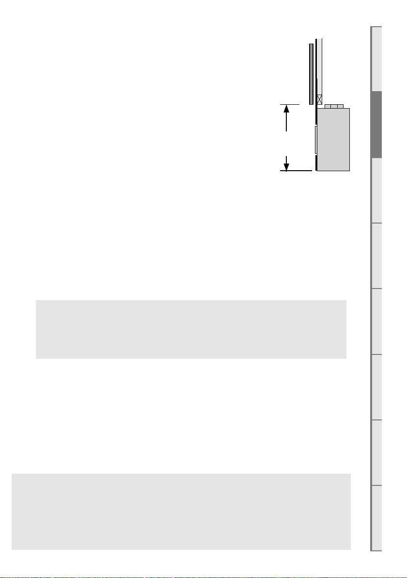
B11 Television Clearances
800
MIN
The following are the recommended minimum clearances for the
location of any electrical equipment (such as a Plasma TV, LCD TV
or home theatre system) above an Escea DX Series gas re.
Note: The above television clearance recommendations are to
be treated as a suggestion of a suitable installation only. It is the
responsibility of the end user to check the installation instructions of their electrical appliances to ensure that the location in
relation to the gas re is suitable. Escea in no way guarantees or
takes responsibility that the above installation suggestion will be
suitable for all electrical or home entertainment appliances.
Note: Dimension from base of appliance.
For installations with a recessed TV above, allow at least 300mm
above the top of the appliance to allow for Duct and ue routing.
B12 Ducting
Note: The duct fan must be installed in a location accessible for service or replacement, a service hatch (to allow for access) may be required.
This gas re requires a small network of ducting situated in either the ceiling or under the
oor to distribute heat generated by the appliance.
A centrifugal fan (separate purchase) is connected to the duct system and this draws air
through the appliance where it is heated, and then distributes it via the ducting network.
The centrifugal fan is powered by the appliance. When placing outlets in rooms other
than the room the appliance is installed, it is important to allow for return air to
equalise pressure between the rooms.
Caution: Provision must always be made for return air from heated rooms
e.g. undercut doors or natural leakage.
ACDEFGSERVICE
B
WARNING: OVERHEATED ROOMS ARE NOT SAFE FOR INFANTS
DX res require a minimum of three outlets in the ducting system to be fully open at all
times. At least two of those outlets must be present in the same room that the re resides
in. There can be a maximum of 5 outlets for the DX1000 and 8 outlets for the DX1500. A
standard duct kit (separate purchase) has provision for the three minimum outlets - You
can use your own ductwork and outlets, but you must ensure they are rated to temperatures of at least 90 degrees Celsius and have an appropriate R-value.
Ductwork must be adequately sized to avoid excess backpressures. Inadequate duct sizes
will cause unnecessary fan noise and premature fan failure.
We recommend removing the close aps from at least three of the duct outlets to prevent unnecessary back pressure and fan noise.
Ductwork must not be crushed or exposed to excessive heat sources.
Note: If duct backpressure is too great, the appliance can shut down due to overheating.
□
This ducting fan will generate mechanical noise. Ideally it must be installed in a position
where noise will not interfere with daily activities. All air ducts will make noise no matter
how well the system is designed. Increasing the number of outlets is a simple strategy to
reduce this noise.
13
Page 14
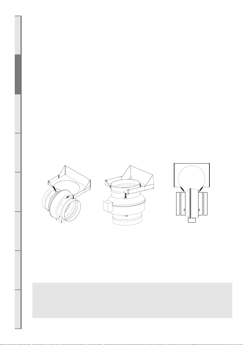
For installations with the duct fan installed in the appliance cavity we recommend:
A C D E F G SERVICE
B
- Contact Escea’s free Architectural Advice Service at [email protected] and forward them
a copy of the intended design for comment.
- The cavity to be clad with sound gib.
- The fan to be wrapped in a sound absorbing material.
- The system be tested for sound related issues before it is enclosed. Please contact
Escea for more information at this stage if advice is needed.
- The duct fan must be hung on the provided hanger.
- The ducting must always have a “C” shape or an “S” shape to break up the sound
waves on both sides of the duct fan.
-The duct fan must be installed in a location accessible for service or
replacement, a service hatch (to allow for access) may be required.
-Never place the fan in such a way to result in a straight run to the top of the re,
as the sound of the fan will echo out the front of the re.
B13 Duct Fan mounting
Using the 3x spring mounts supplied, the duct fan should be installed in one of the
following positions as shown below. You must use the spring mounts as this will help
decrease noise by not transferring vibration into the walls.
Note: The duct fan must be installed in a location accessible for service or replacement, a service hatch (to allow for access) may be required.
Run the electrical cable from the duct fan to the cavity where the appliance will be installed. Ensure the cable is not draped over or in contact with the outer shell of the appliance or either of the exi ue tubes and kept clear from any other possible heat sources.
Fix it appropriately and allow enough cable loop to prevent tension on the cable plugs.
The duct fan unit length is approx 350mm and diameter is approx 340mm.
The duct fan must not be exposed to the outdoors.
END OF SECTION B
By the end of this section, you should have:
□ A framed, but un-lined, cavity sized to suit your fascia and ue conguration
□ Provision for sucient access to the powerue for future servicing
14
Page 15
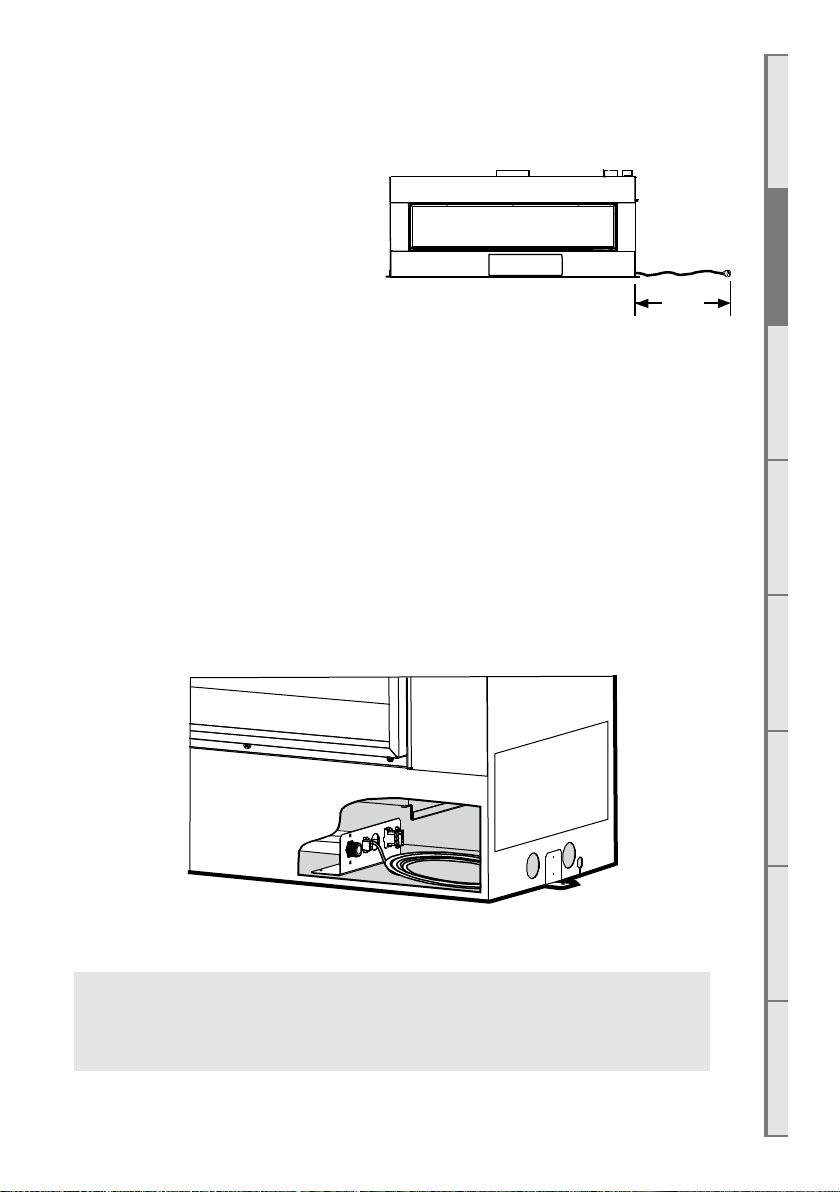
C
1m
Installing the Electricity and Gas to the Appliance
C1 Power Supply
While the cavity is being created
consideration should be given to
appropriate location of a standard 3 pin,
EARTHED 230/240V power outlet. This
must be within 1.0m of the bottom right
of the appliance.
IMPORTANT: Locating the power outlet within the cavity makes the installation very neat
but provision MUST be made to be able to switch the power supply o and on (electrical isolation switch) and MUST be accessible after the heater has been installed. This is
normally done by means of a separate switch located outside of the cavity and wired to
the plug. This will allow technicians to isolate the power supply before servicing the appliance.
This appliance must not be located immediately below a socket outlet.
This appliance will draw a maximum of 2 Amps from a 230/240V supply.
No additional power supply is required for the power ue.
C2 Network Cable
A 5 meter length of network (Ethernet) cable has been supplied and is coiled inside the
lower right of the replace. Access this via the removable access panel, and connect it to
the buildings modem.
ACDEFGSERVICE
B
If you do not wish to connect the replace to the modem, the Network /
Ethernet cable should be run to somewhere accessible by a service
technician, such as a cupboard.
15
Page 16
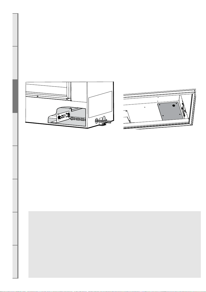
C3 Gas Pipe Sizing
Gas pipe should be sized as per the requirements of AS/NZS 5601.1. The pipe sizing must
A C D E F G SERVICE
B
be sucient to deliver the following volume of gas to the heater with all other gas appliances in the home running at the same time:
C4 Gas Pipe Position
The gas connection is inside the appliance and is ½” male BSP on the lower right of the
appliance as shown. Access is through the bottom of the rebox via a hatch (shaded grey
in the right diagram).
C5 Gas Isolating Valve
A gas isolating valve must be installed in the gas line as close to the appliance as possible.
Fix it in a convenient position to allow it to be closed o quickly and easily during normal
operation. Take into consideration access to this valve once the wall linings are on. This
will also allow for easier servicing in the future.
DX1500 Gas Consumption = 42MJ/hr
DX1000 Gas Consumption = 33MJ/hr
END OF SECTION C
By the end of this section, you should have:
□ An unlined cavity with 230/240V AC supply that the appliance can be plugged into
□ An electrical isolating switch that is accessible once the appliance is installed
□ A suitably sized gas supply to the right hand side of the appliance with a pressure
test point, ready to be connected once installed
□ Network cable installed, ready for plugging into appliance, regardless of being
connected to internet router/network or not
16
Page 17
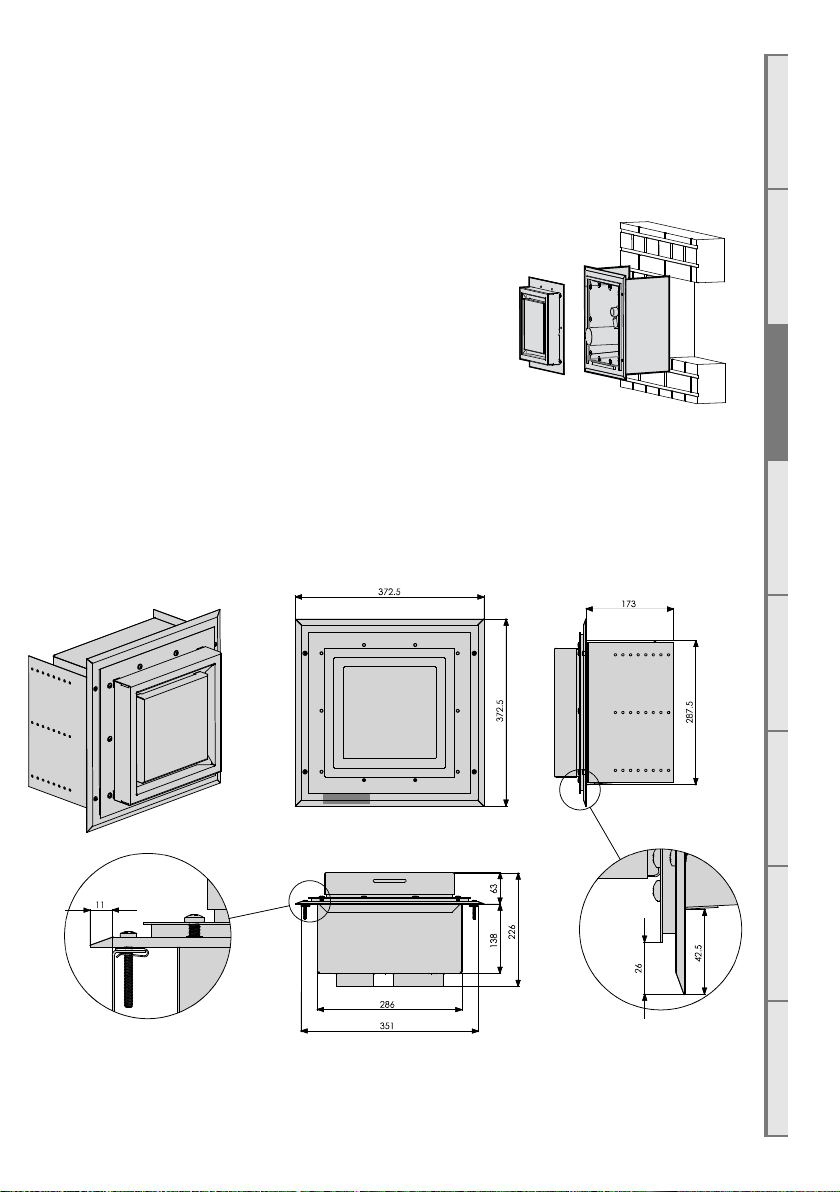
D
Installing the Flue
Note: The appliance is designed to operate using the approved exible ue supplied by
Escea. Using other brands of ue may aect the appliance warranty.
D1 Installing the Horizontal Powerue Wall Terminal option
The Horizontal Powerue Wall Terminal must be installed in
the correct orientation. This allows for the correct operation
of the ue system and prevents the ingress of water.
The Horizontal Powerue Wall Terminal must be weathertight when installation is complete to prevent damage to
the dwelling. It must be installed by a suitably qualied
person.
Fit the Horizontal Powerue Wall Terminal into the hole and x in place, making sure the
installation is sealed appropriately to prevent the ingress of water from outside the wall
cladding. Take notice of the label on the termination which shows the correct orientation
that the terminal should be tted.
NOTE: It is the responsibility of the installer to ensure the Horizontal Powerue Wall Terminal is installed to all relevant building codes to ensure weather tightness.
ACDEFGSERVICE
B
17
Page 18
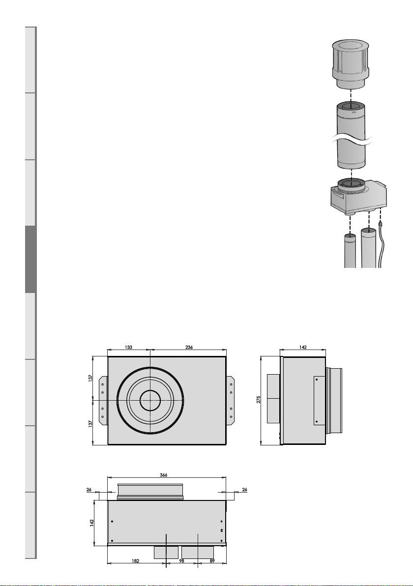
D2 Installing the Internal Vertical Powerue (Duravent)
The internal vertical ue(duravent) option is designed to have
A C D E F G SERVICE
B
the box containing the fan and electricals mounted within the
roof space of the house, and the vertical 200mm diameter twin
wall ue penetrate through the roof. The standard kit comes
with 1.2m of twin wall ue (post fan), for alternative lengths,
contact Escea. Note total combined maximum vertical ue
before the fan must be less than 12metres (max 4m Flexi+ max
8m polypro).
Use standard methods to ash the roof penetration, the installation must be weather proof and conform to all local council
standards including powered ue roof termination rules.
The cowl surround should be xed in place as shown
Mount the fan assembly box to roof framing using timber or
builders strapping, ensuring the ue is vertical and rigidly
mounted.
Aim to have the fan box mounted as high as possible, mainly to
allow sucient fall for condensation drainage if the exi-ue is
to run horizontally.
Ensure there is sucient space below fan box to have access to
t the exi-ue tubes and to allow owing bends if required.
Note: The vertical powerue and the exi ue connections must be installed in a
location accessible for service or replacement, a service hatch or removable ashing
to allow for access may be required.
18
Page 19
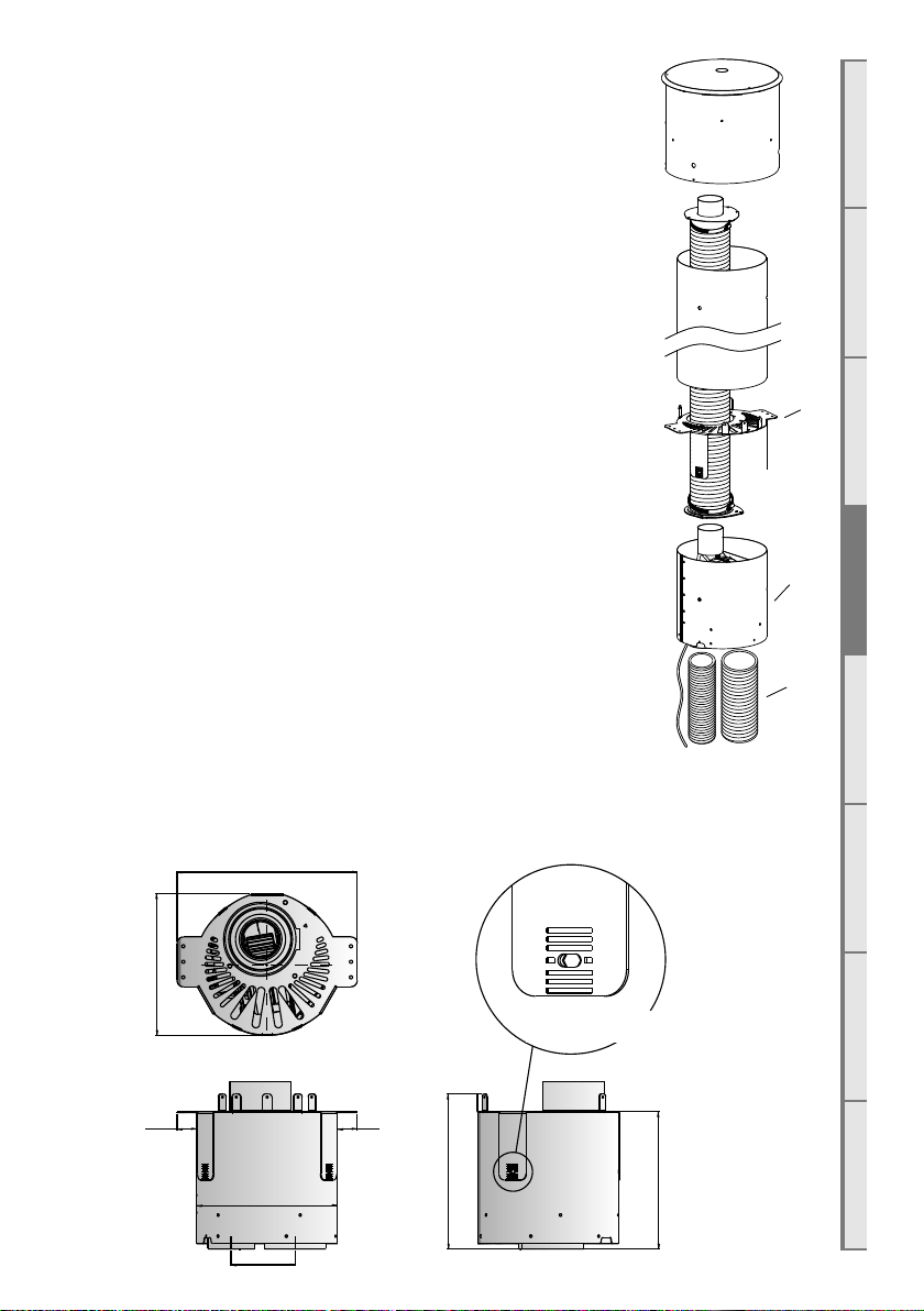
D3 Installing the Universal Vertical Powerue (Internal Install)
(1)
(2)
(3)
290
229.1
ø226.8
31.6
221.8
250.2
31.6
103.4
TIMBER MUST NOT
OBSTRUCT THESE ZONES
Note: For information regarding an external install of the UVP, go to
section D4.
The UVP Internal conguration is designed to have the fan, mounted within the roof space of the house, and the vertical ø225mm
diameter liner, containing a ø100mm exi, penetrate through the
roof. The UVP internal conversion kit comes with 1200mm liner
which is specic to the internal installation and must always be
used.
Note: The ue setup must comply with section B3 or B4.
Use standard methods to ash the roof penetration, the installation
must be weather proof and conform to all local council standards
including powered ue termination rules.
Mount the fan mount bracket(1) to the roof framing and strapping
using timber ensuring that the ue is rigid and vertical. Ensure that
the mounting timber does not obstruct access to the 3xM5 screw
threads on the side of the fan unit.
Aim to have the fan enclosure(2) mounted as high as possible,
mainly to allow sucient fall for condensation drainage if the exiue is to run horizontally.
Ensure there is sucient space below fan enclosure(2) to have access to t the exi-ue tubes(3) and allow owing bends if required.
Note: The UVP-Internal and the exi ue connections must be installed in a location accessible for service or replacement, a service
hatch or removable ashing to allow access may be required.
Note: When installing the unit onto a ue liner, ensure the length of ue liner above the
roof is the minimum required length.
ACDEFGSERVICE
B
19
Page 20
A C D E F G SERVICE
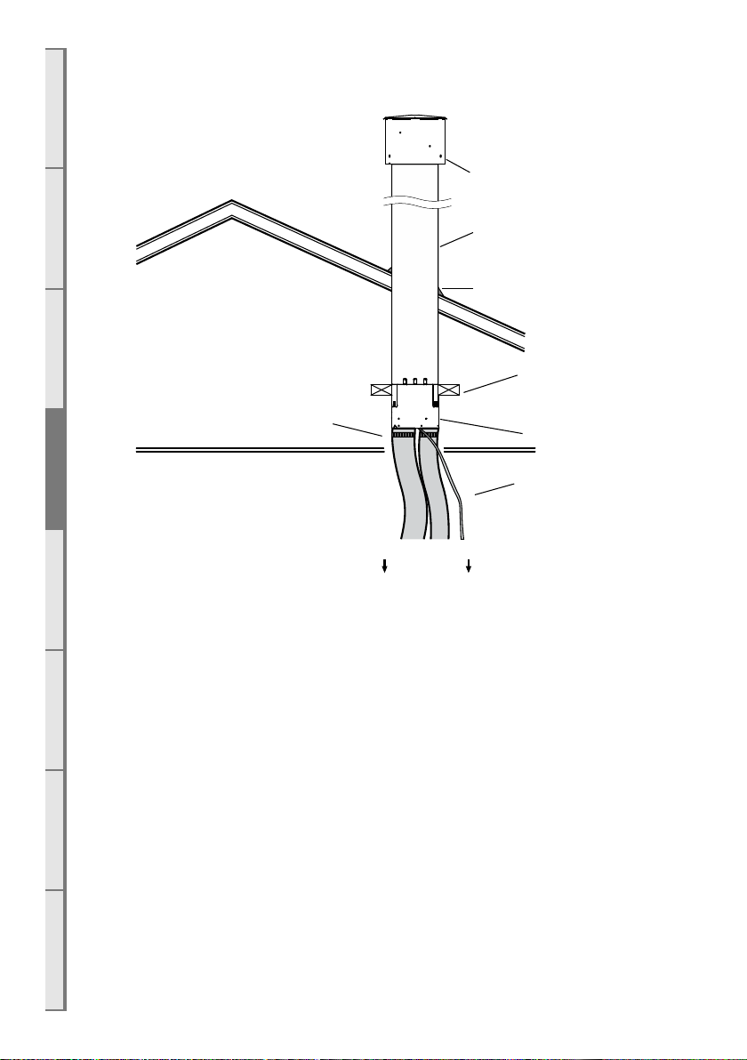
The UVP-Internal kit is intended for use within an accessible roof space or ‘chimney’ construction. Service access must be provided.
Ensure installation complies with relevant building codes and regulations
Typical Installation UVP Cowl
B
Roof Space
Hose band clamps
To appliance
1.2m F-F Liner
‘Decktite’ or similar ashing
Ensure Power Flue unit
is securely braced using
integral brackets.
UVP Fan Unit
Power cord to
appliance
Ø75mmØ100mm
20
Page 21
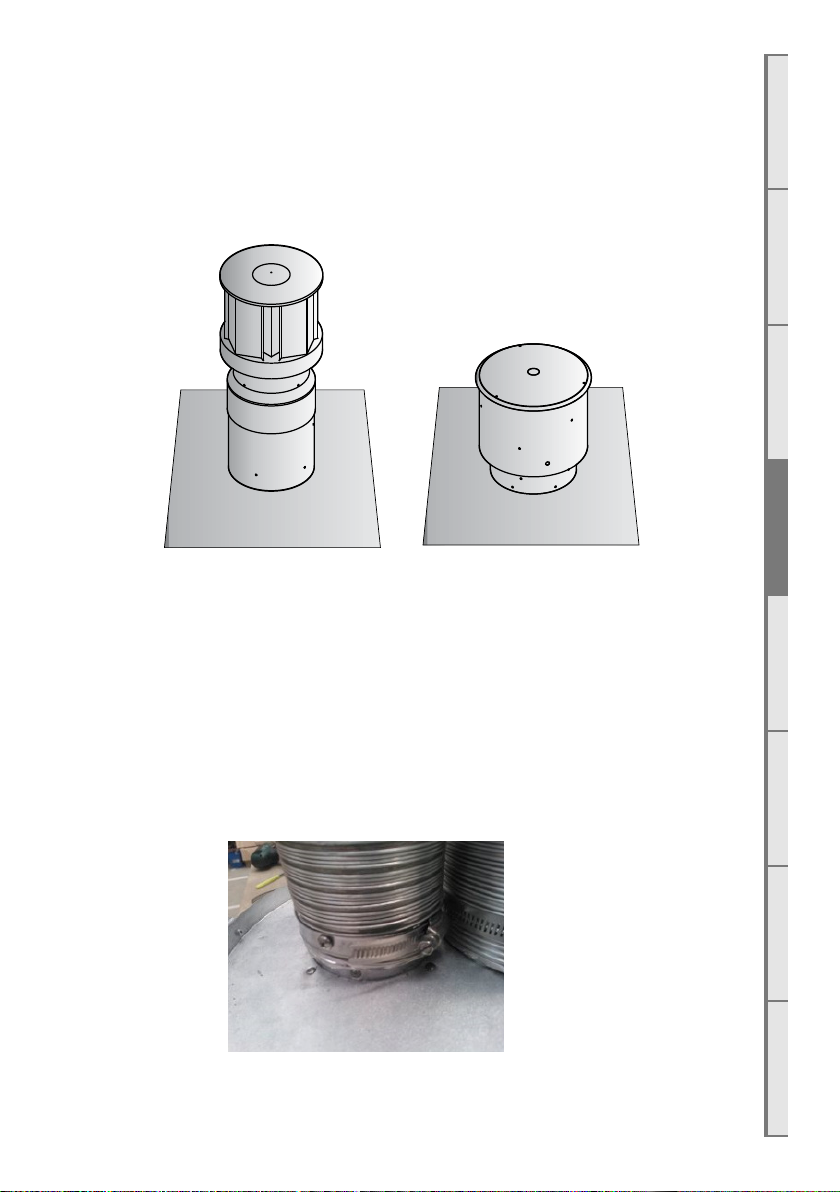
D4 Installing an External Vertical Powerue (EVP or UVP)
Note: For information regarding an internal install of the UVP, go to section D3.
The EVP and UVP are designed to have the enclosure containing the fan unit mounted
externally.
The cowl surround should be xed in place as shown.
Depending on the kit purchased, mount the EVP/UVP kit to the top of a chimney ashing
plate or penetrate the roof with an optional ue liner accessory and t the EVP or UVP kit
over the ue liner; sealing the penetration with a decktite or similar ashing. Ensure the
terminal is vertical and rigidly mounted and the exi ue attached below is xed to the
terminal spigots using the supplied hose clamps and is held in place by drilling 3 holes
and screwing 3 self tapping screws evenly around each hose band clamp (as shown in the
picture below).
ACDEFGSERVICE
B
Note: When installing the unit onto a ue liner, ensure the length of ue liner above the
roof is the minimum required length.
21
Page 22
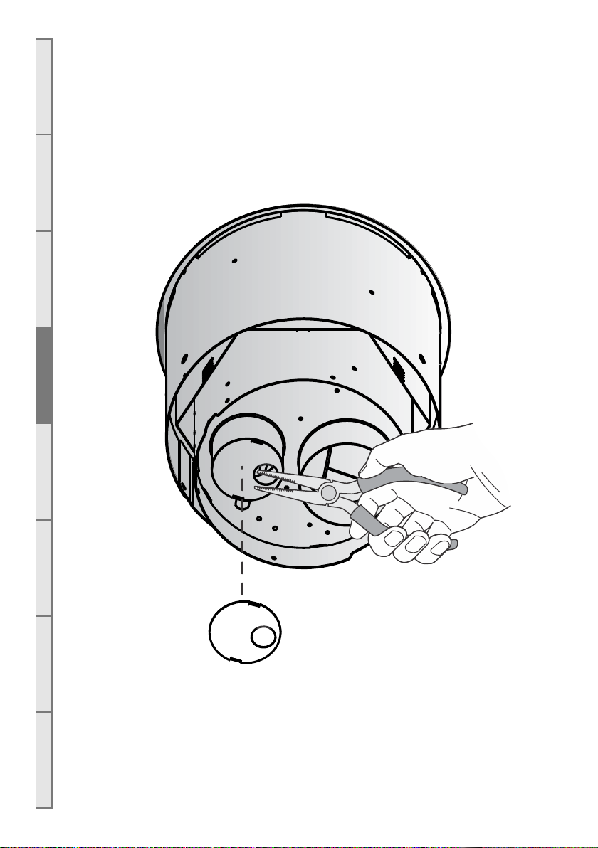
D5 Removing the restrictor plate (EVP, UVP External and Internal Only)
A C D E F G SERVICE
B
For every DX-series installation with an EVP, UVP-External or UVP-Internal, the attached
restrictor plate must be removed . To do this:
□ Turn the unit on its head and identify the restrictor plate attached to the ø75mm spigot.
□ Break the restrictor plate with a pair of snipers, pliers, or other means necessary. (Do not
damage the ø75mm spigot).
22
Page 23
D6 Installing in Accordance with Relevant Codes
N
R
F
S
W
U
A
V
K
Q
E
J
J
A
H
E
D
C
C
A
O
G
J
L
B
M
P
Prohibited area for flues is
below or Distance 'E'to
the left andright of the
Electricity meter
or fuse box
M =Gas Meter
P = Electricity meter orFuse box
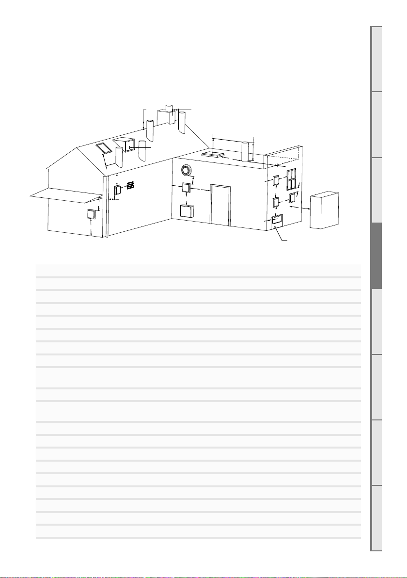
The location of the Powerue Terminal must be installed in accordance with AS/NZS
5601.1 and any other relevant building codes. Avoid installing the Powerue Terminal in
areas exposed to high winds and extreme weather, if possible.
Some of those minimum clearances for a fan assisted terminal are listed below; please
refer to AS/NZS 5601.1 Gas installation standard for full guidance on the design of the
ue system. Where possible allow a greater clearance.
A Below eaves, balconies and other projections 200mm
B From the oor, above a balcony or other surface 300mm
C From a return wall or external corner 300mm
D From a gas meter or regulator vent 1000mm
E From electricity meter or fuse box 500mm
F From a drain pipe or soil stack 75mm
G Horizontally from any building structure or obstruction 500mm
H From any other ue terminal or combustion air intake 300mm
J Horizontally from any openable window, door, non-mechanical air inlet, or any other
opening into a building with the exception of sub oor ventilation
K From a mechanical air inlet or spa blower 1000mm
L Vertically below any openable window, door, non-mechanical air inlet, or any other
opening into a building with the exception of sub oor ventilation
N Horizontally from a roof light 600mm
O Vertically from a roof light 500mm
Q Vertically from a flat roof 500mm
R Horizontally from a vertical structure 500mm
S Below a roof window 2000mm
T Above or either side of a roof window 600mm
U From a dormer window 1500mm
V Above the apex of the roof (see note 1 on following page) 300mm
W From an open flue 1500mm
ACDEFGSERVICE
B
300mm
300mm
23
Page 24
D7 Creating the Hole in the Outside Wall
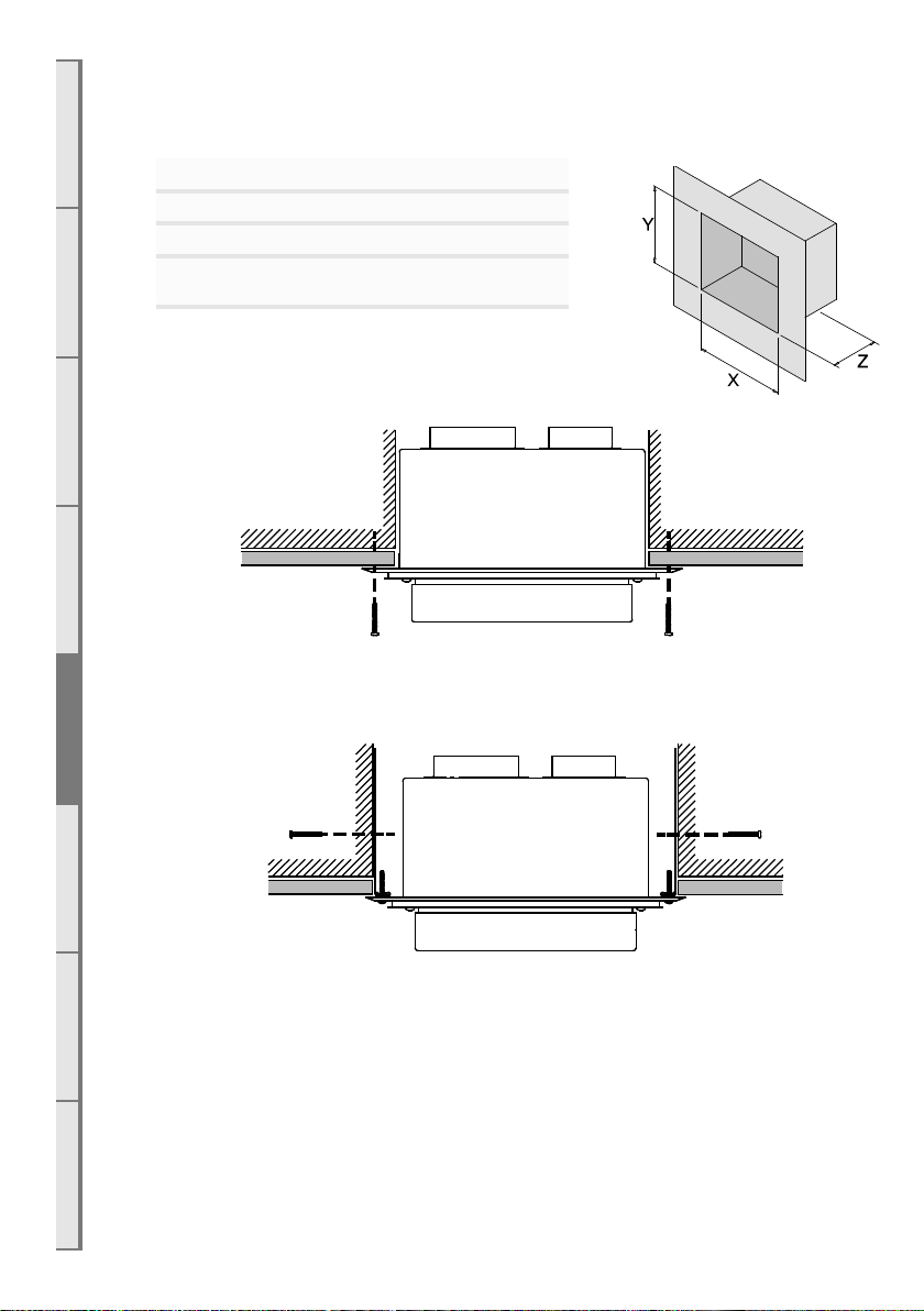
When cutting the hole in the outside wall, be mindful of how the installation Horizontal
A C D E F G SERVICE
B
Powerue Wall Terminal will be nished, the installation must be weatherproof.
Ideal hole/cavity size for Horizontal Powerue
X 298mm
Y 298mm
Z 175mm Excluding allowance
for ue which exits here
The Horizontal Powerue Wall Terminal can be attached to
the wall in two ways,
A) From the front of the terminal:
B) By attaching the optional Wall Terminal Installation Brackets to the sides of the cavity
and attaching the Horizontal Powerue Wall Terminal to these, from the front:
24
Page 25
D8 How to ash the Horizontal Powerue
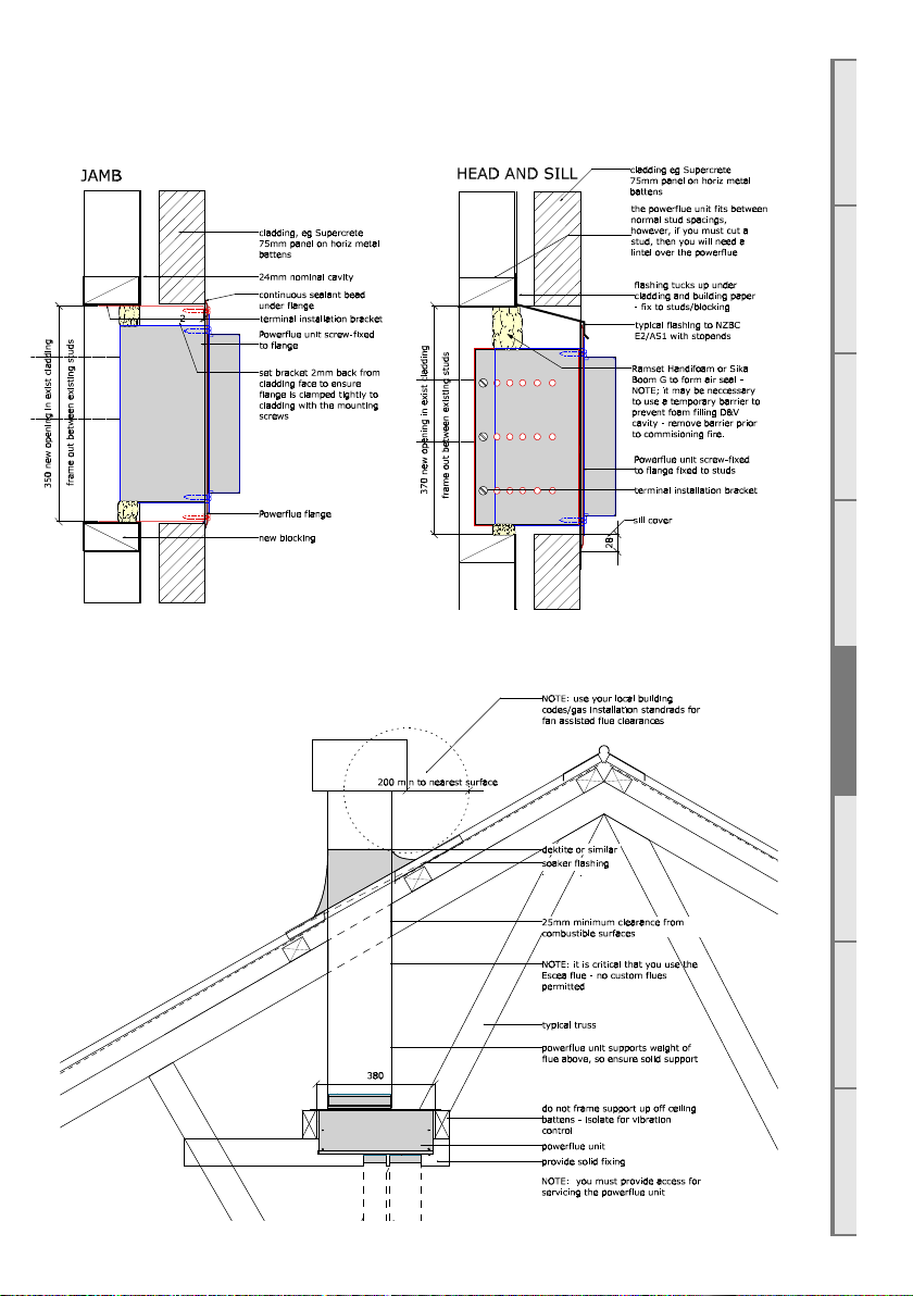
The following diagrams are excerpts from the escea architect drawings, and are available
in full on our website. These diagrams are recommendations, and your installation must
comply with any local or national building codes.
D9 How to ash the Vertical Powerue
ACDEFGSERVICE
B
25
Page 26
D10 Running the Flue
If your ue system is greater than 4m long (as shown in diagrams below), then a exible
A C D E F G SERVICE
B
ue with condensate trap and rigid PolyPro tube ue lengths is required (see textbox at
end of section for more info).
Run the Ø100mm ID and Ø75mm ID (Ø110mm OD & 85mm OD) exible aluminium
hoses from the cavity to the rear of where the Horizontal Powerue Wall Terminal will be
installed in the outside wall. The ue system for the DX1500 / DX1000 is zero rated,
so no spaces are required between the ue and any timber framing. Allow enough
stretch in the exible aluminium ue to allow it to be able to sit just outside of the wall.
Note: The exible ue is shipped in a ‘compressed’ form. Extend it to your desired length
by stretching (up to 4m maximum per length).
FOR MORE INFORMATION ON INSTALLATION OF THE POLYPRO FLUE, SEE ‘POLY
PRO FLUE INSTALLATION INSTRUCTIONS’ AVAILABLE ON:
WWW.ESCEA.COM
OR SUPPLIED WITH THE FLUE.
FOR POLY PRO COMPONENT GUIDES, THESE ARE AVAILABLE ON:
WWW.ESCEA.COM
HORIZONTAL FLUE COMPONENT GUIDE &
VERTICAL FLUE COMPONENT GUIDE
D11 Running the Powerue Electrical Cable
Note: The Horizontal Powerue Wall Terminal is powered from the appliance, and must be
connected to the appliance with the supplied electrical cable only.
TITLED:
The supplied electrical cable is 7m long with standard 6m ue kits, and ue extension kits
also include a Powerue electrical cable extension.
Run the electrical cable from the cavity where the appliance will be installed to the hole
in the outside wall. Ensure the cable is not draped over or in contact with the outer shell
of the appliance or either of the exi ue tubes and kept clear from any other possible
heat sources. Fix it appropriately and allow enough cable looped to be able to pull the
Horizontal Powerue Wall Terminal out from the installed position should servicing be
required.
END OF SECTION D
By the end of this section, you should have:
□ A weather-tight Horizontal Powerue Wall Terminal installation with clearance as
specied by AS/NZ5601.1
□ Reasonable access to the outside face for maintenance purposes.
□ Flue attached to the rear of the Horizontal Powerue Wall Terminal leading back to
the appliance.
□ The electrical cable from the Horizontal Powerue Wall Terminal attached to the rear
of the installation and run back to the appliance cavity in an electrically safe manner.
26
Page 27
E
Installing the Appliance
E1 Double Sided conversion
If the appliance is to be double sided,
you will have been supplied with an extra
glass panel and steel support frame and
wall lining trim brackets.
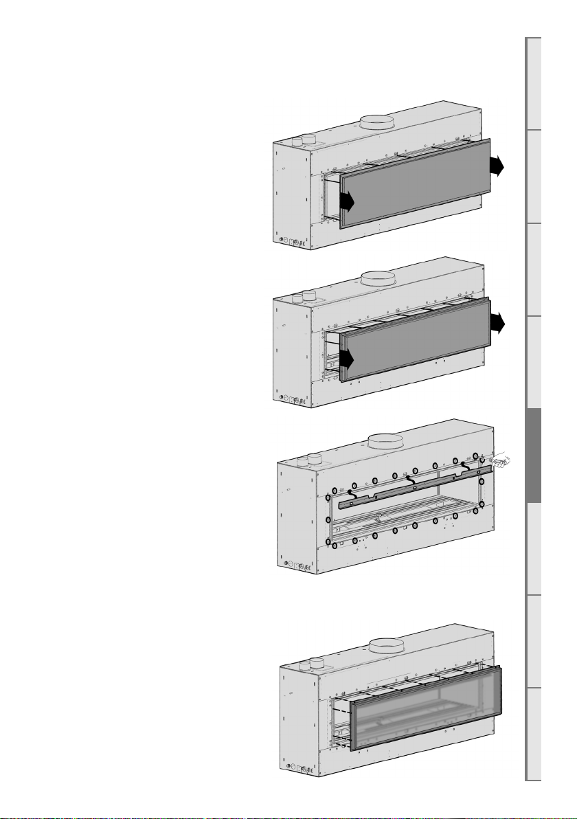
1. On the rear of the appliance, unscrew
the outer shell cover and remove it as
shown
2. Unscrew the Firebox rear panel and
remove it. Sometimes extra force may
be required to remove this panel as the
sealing tape can ‘glue’ itself to the painted
surface.
ACDEFGSERVICE
B
3. Screw the Wall Lining trim brackets
on to the appliance chassis as shown in
photo.
4. Carefully install the extra glass panel
and frame onto the appliance, ensuring
that the glass does not fall from the frame.
Tighten the bolts around the outside of
the glass retainer until securely tted.
27
Page 28
E2 Installing the Appliance
A C D E F G SERVICE
Insert the gas re into the cavity and bolt down in correct
position using the brackets on each end of the appliance.
It is a requirement that this appliance be securely fastened
at the base.
□ On the right hand side of the appliance:
B
□ Connect the powerue electrical cable.
□ Connect the Duct fan electrical cable
□ Plug the appliance Mains power electrical cord into the
230/240volt outlet in the cavity.
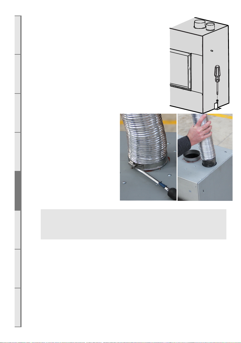
E3 Connecting the Flue
Access the top of the appliance and
connect both the inlet ue (Ø75mm
ID / 85mm OD) and the exhaust ue
(Ø100mm ID / 110mm OD) to their
respective spigots. Tighten the hose
clamps onto the spigots. Ensure the
ue connection is air tight. Sealant is
not required.
WARNING: The ue connection MUST be secured with the clips provided and
tape MUST NOT BE USED. If any of the ue pipe is damaged and integrity
compromised then it should not be repaired with tape, it should be replaced.
Connecting the Ducting
Attach the ducting to the top of the appliance at the 250mm diameter spigot and secure
using a clamp or appropriate ducting tape to ensure an airtight joint.
E4 Connecting the Network Cable
A network cable has been attached to the appliance. This must be left accessible even if
not being used, to make future servicing or upgrades easier. To access the network cable,
open the access hatch on the base of the rebox (underneath the burners) and feed the
cable through the holes in the outer chassis where the power and gas lines are.
28
Page 29
E5 Removing (and replacing) the Glass
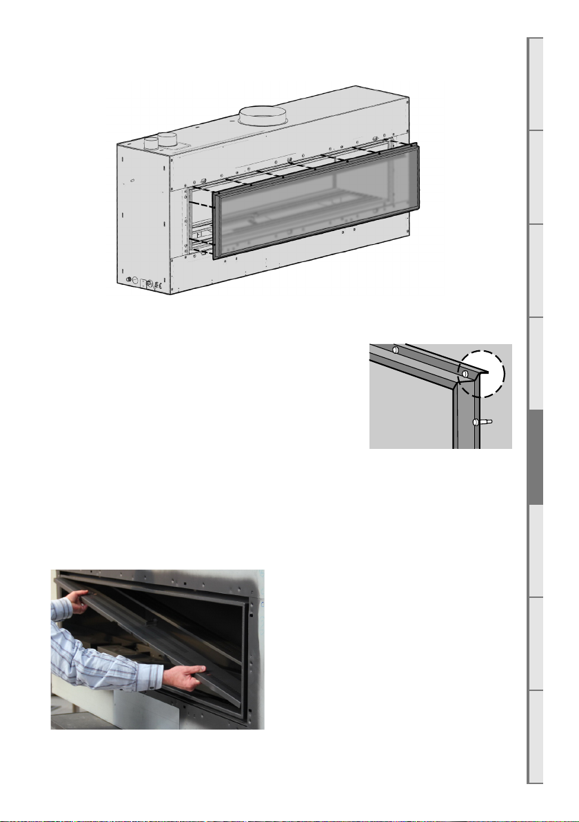
Using the supplied 3mm Allen Key (hex drive) remove the bolts around the glass retainer
ensuring that the glass does not fall forward.
Pull the top of the frame toward you slightly and lift the glass and frame out and away
from the re. Place the glass & frame carefully aside.
NOTE WHEN REPLACING THE GLASS:
When replacing the glass, note that the metal ange shown
to the right must be on top (not the bottom), or the glass will
not t correctly to the replace.
ACDEFGSERVICE
B
E6 Remove the Fuelbed Tray & Burners
Remove the Fuelbed tray from the re box, by lifting one end up into the top corner and
then out towards you. Take care not to scratch the rebox paint and lift out the burners.
29
Page 30
E7 Gas Type Conversion
THIS APPLIANCE IS CONFIGURED TO OPERATE ON NG
A C D E F G SERVICE
B
If gas type conversion is not required then jump to “checking operating pressure”
Note: Access to the valve and control system can be through either of the 2 hatch panels
shown shaded black in the diagram of section E8.
Your gas re has been supplied with the necessary parts for gas conversion. Follow the
steps on the following page to change from NG to ULPG/Propane or vice versa.
WARNING: The regulator that is supplied with the re MUST NOT BE REMOVED.
Removal of the regulator, or replacing it with one not intended for use with this Escea re,
will void the limited appliance warranty.
Turn o power and gas rst
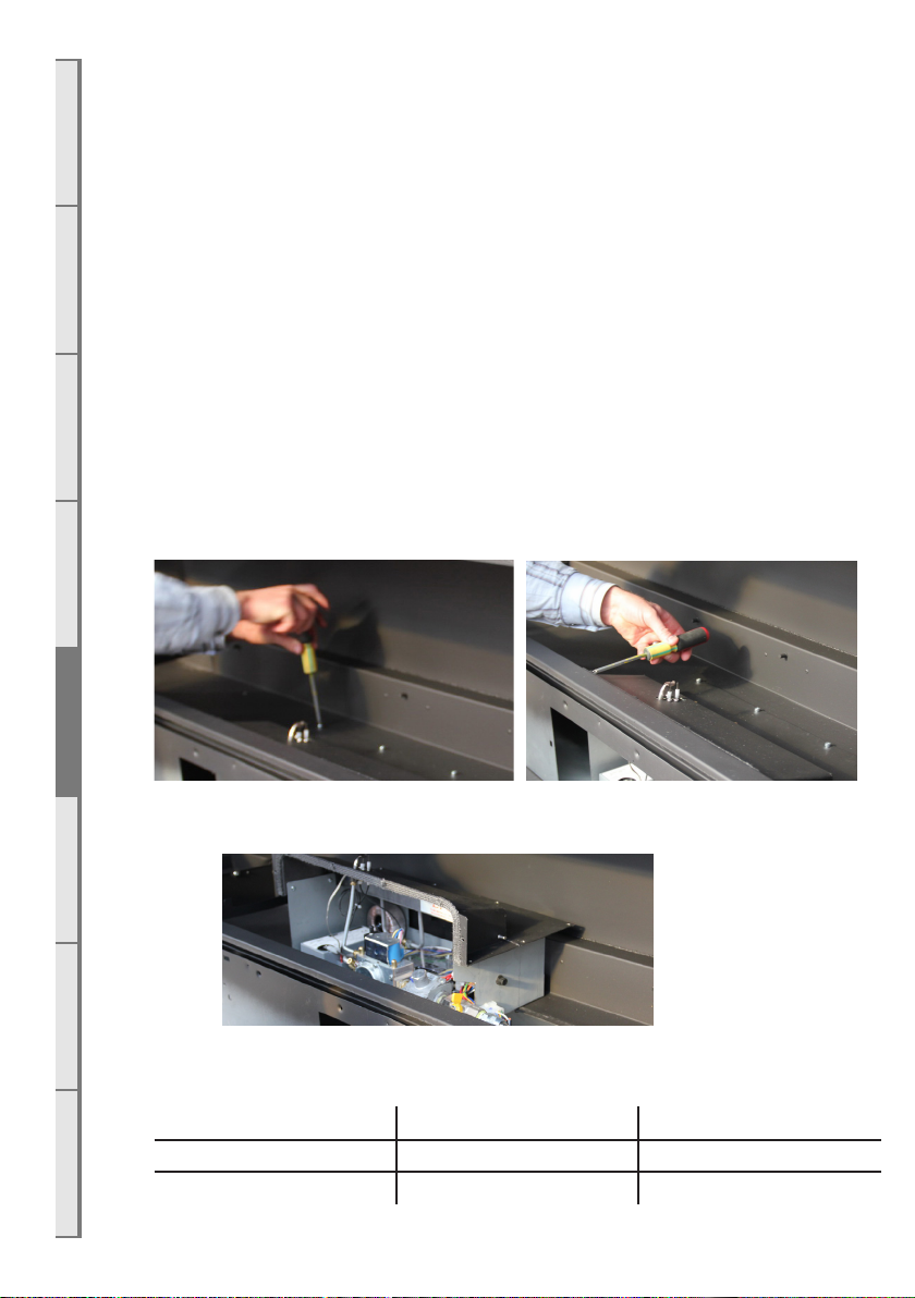
Step 1: Ensure power and gas is o. Remove the fascia, glass and fuelbed as per
section E6
Step 2: Lift out the two burners and the surrounding perforated grill as per section E7.
Step 3: Remove the screws in the bottom and the inner side of the rebox as per shown.
Remove ‘engine’ by lifting up and to the left. This is still connected internally to the gas
hose and power cables. Place engine just to the left within rebox as shown.
Step 4: Change the two main burner jets with the jets supplied in kitset.
DX1500 DX1000
NG (Both jets) Ø2.3mm Ø1.95mm
Propane / ULPG (Both jets) Ø1.3mm Ø1.10mm
30
Page 31
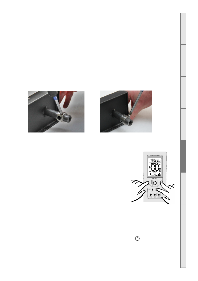
Step 5: Remove the regulator screw cap and screw out the nylon adjuster screw to
remove the existing spring. Replace the spring with the purple spring supplied in the
conversion kit and reassemble the regulator.
Step 6: Cover the existing gas type label (located on underside of hatch shown in
section C4) with the new gas type label supplied in kitset. Ensure serial number and date
of manufacture are still visible. Write your name, company (if appropriate) and date of
conversion on new label with permanent marker.
ACDEFGSERVICE
Step 7: Place engine back into rebox. Take care not to pinch any wires. Don’t replace
the screws at this stage.
Step 8: The burner tubes on both burners have convertible collars. Ensure the collars on
both are set to the correct orientation. Place one burner only into position.
ULPG/Propane NG
11mm hole exposed 3.5mm hole exposed
Step 9: Adjusting the electronic controller for gas type
Ensuring the gas is still OFF, Turn the power ON.
On the remote control, insert the new “AA” size batteries. You
should now see the time on the display showing 0:00
Press the MINUS (4), PLUS (8) and FAN BOOST (7) buttons
simultaneously (as shown right) until the characters “03” light
up on the display. Release the buttons and the remote will
count down and display “GO”. The screen will then display all
characters. This will put the remote into test mode and the
two big temperature digits should begin counting from 0 to 99
repeatedly.
B
Now hold down the “Edit Timer” button and “Activate Timer” button simultaneously, the
remote display will show the current conguration of either “NG” for Natural or “LP” for
ULPG/Propane. To change this conguration, hold down the same 2 buttons “Edit Timer”
and “Activate Timer” simultaneously for 5 seconds. This will now have toggled between
gas types.
Once you are have chosen the correct gas mode, simply press the “ ” power button
once to exit this diagnostics mode.
31
Page 32
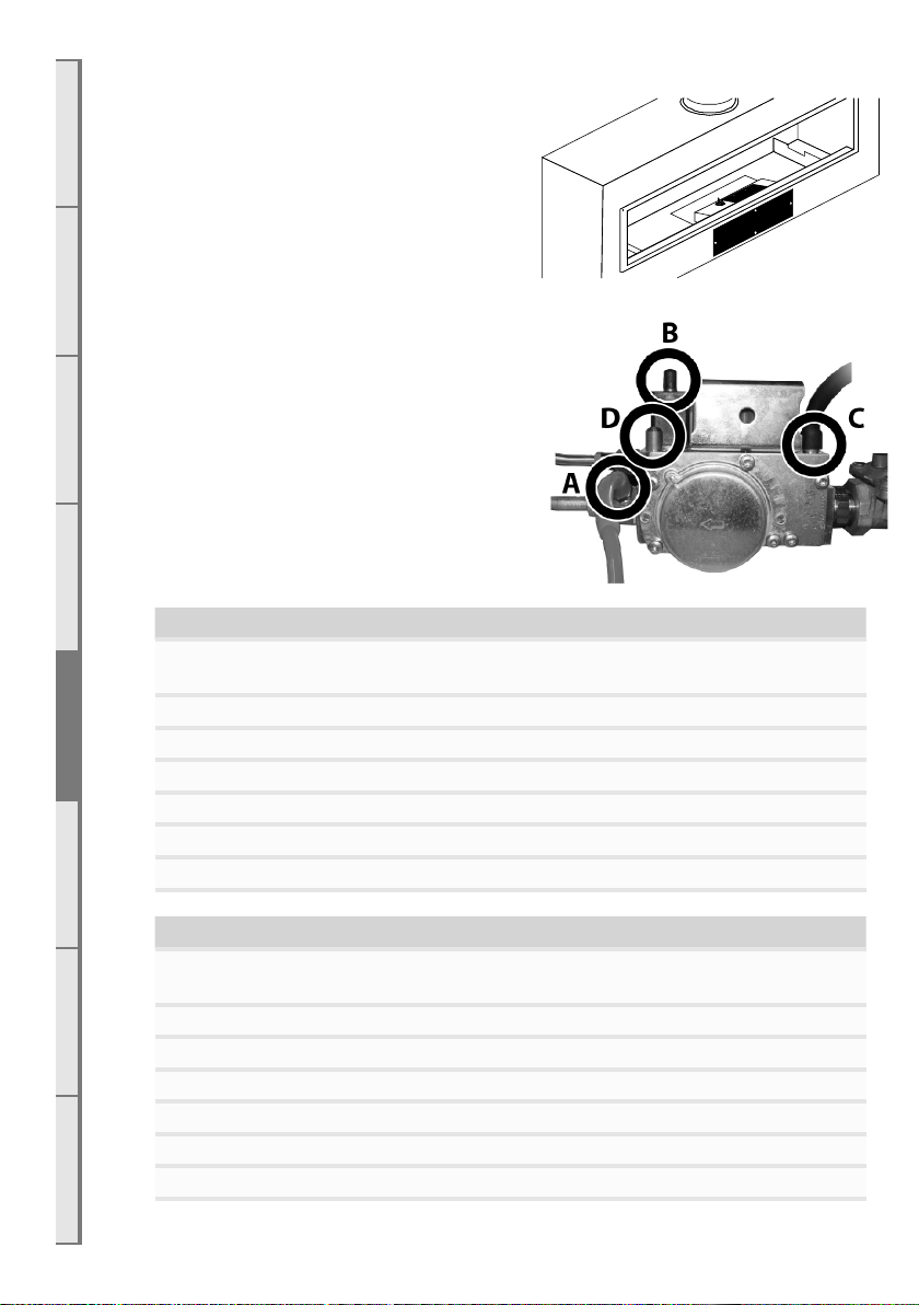
E8 Checking the Gas Operating Pressure
A C D E F G SERVICE
B
Note: Access to the valve and control system
can be through either of the 2 hatch panels
shown shaded black in the diagram to the
right.
Note: ensure the thermostat control within the
remote does not cause the ame to modulate
down by increasing the set temperature and
keeping the remote in a cool environment
Turn on the gas. Turn the power on.
Check the inlet pressure upstream of the appliance using the test point that you installed
earlier.
Note: The regulator that is supplied with the
re MUST NOT BE REMOVED. Removal of the
regulator, or replacing it with one not intended
for use with an Escea re, will void the limited
appliance warranty and may be dangerous.
The gas valve is shown right with Manometer
test points at A or D and C.
Gas Pressure Table - DX1000 Gas Type
Propane (AUS)
Natural Gas
or ULPG (NZ)
Minimum Inlet Pressure - Pre-Regulator 2.75 kPa 1.13 kPa
Maximum Inlet Pressure - Pre-Regulator 5.0 kPa 5.0 kPa
Operating Pressure when on high - (Point A or D) 2.32 kPa ±5% 0.82 kPa ±5%
Operating Pressure when on low - (Point A or D) 0.72 kPa ±5% 0.28 kPa ±5%
Max operating pressure - at burner jet 2.30 kPa 0.76 kPa
Operating pressure - Post-Regulator (Point C) 2.30 kPa 1.00 kPa
Gas Pressure Table - DX1500 Gas Type
Propane (AUS)
or ULPG (NZ)
Minimum Inlet Pressure - Pre-Regulator 2.75 kPa 1.13 kPa
Maximum Inlet Pressure - Pre-Regulator 5.0 kPa 5.0 kPa
Operating Pressure when on high - (Point A or D) 1.96 kPa ±5% 0.76 kPa ±5%
Operating Pressure when on low - (Point A or D) 0.96 kPa ±5% 0.28 kPa ±5%
Max operating pressure - at burner jet 1.94 kPa 0.75 kPa
Operating pressure - Post-Regulator (Point C) 2.30 kPa 1.0 kPa
32
Natural Gas
Page 33
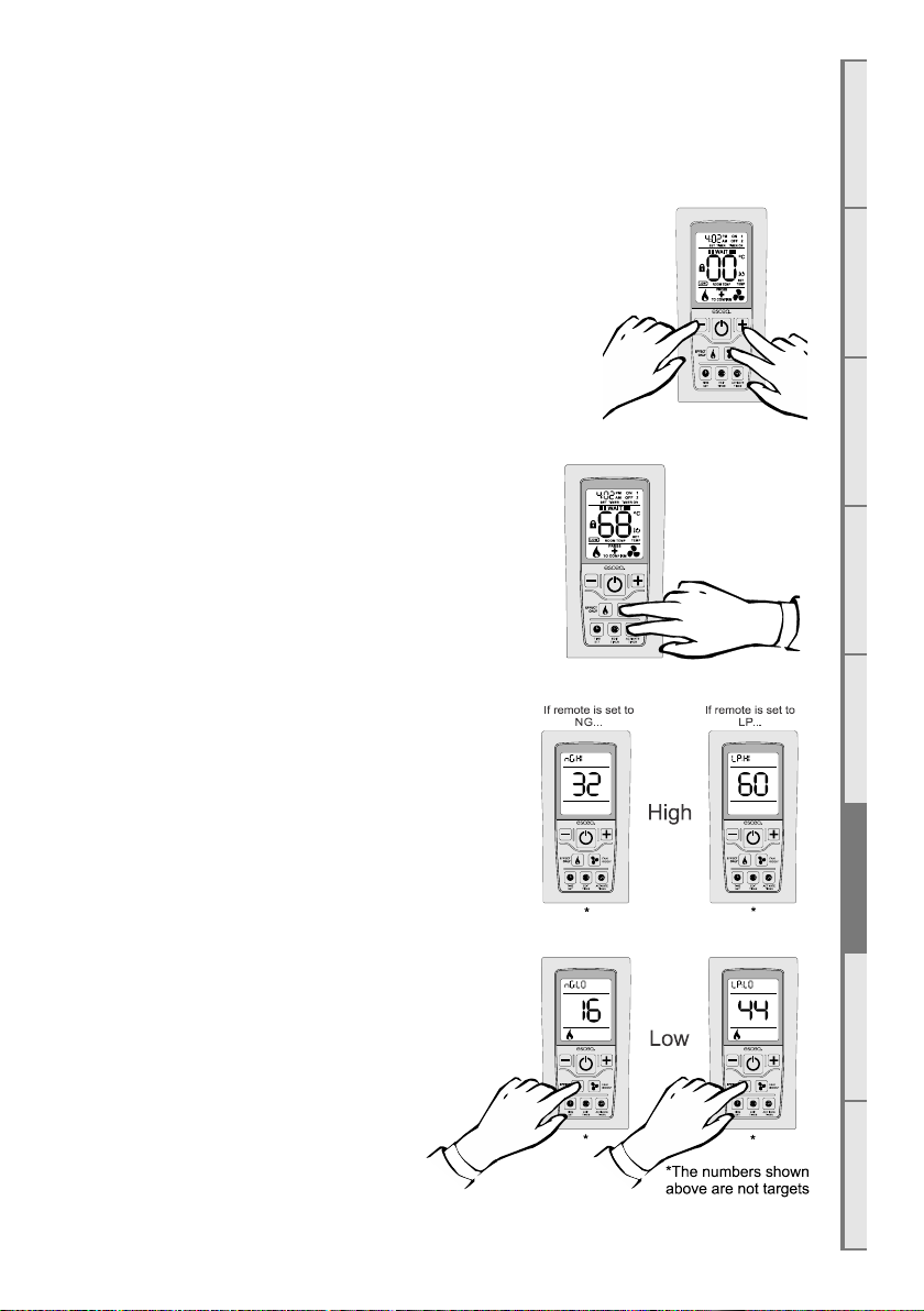
Loosen test point C (shown in diagram above) and attach a manometer tube in preparation for measuring the operating pressure - post regulator.
Turn the re on high and adjust the operating pressure at the regulator.
Once the operating pressure - post regulator - is set, check the operating pressure at test
point A or D ( Shown in the rst diagram of this section).
Changing the Operating Pressure from the Remote
ACDEFGSERVICE
The following instructions must only be undertaken by a suitably approved
person. Any tampering by an unauthorized person will void the product’s
warranty and may result in a dangerous condition.
While the remote is in its “OFF” mode with only the time showing on the
display, press the MINUS, PLUS and FAN BOOST buttons simultaneously (as shown right) until the characters “03” light up on the display.
Release the buttons and the remote will count down and display “GO”.
The screen will then display all characters and should be reading 00. This
will put the remote into test mode.
Whilst in test mode: press and hold
the “Activate Timer” and “Fan Boost” buttons for
4 seconds to access the gas valve settings. The appliance will
automatically turn on while in this mode.
WAIT; allow the appliance to fully light all burners before continuing.
The high setting for the currently set gas type is
displayed first (indicated in
the clock segments at the top). Pressing the plus
or minus keys will change the setting up or down
respectively and change the gas pressure measured
at point A or D. The large digits will blink rapidly
after the setting is made until the verification is
received from the fire.
Note: the numbers displayed on the remote should
only be used to achieve the correct pressure. The
numbers by themselves don’t represent anything
and should not be relied upon.
B
Toggling to the low setting is done by pressing the
“Flame Eect” button (indicated in the clock segments at the top and by the “Flame Eect” icon
at the bottom). Settings are made with the Plus
Minus buttons as above. Exiting this mode is by
pressing the on/o button.
33
Page 34
E9 Operating the Appliance
A C D E F G SERVICE
B
Turn on the re by pressing the “ ” power button the remote and within a few seconds
the appliance will begin its startup sequence, with a 15 second purge of the ue fan.
After purge it will arc It may take a few attempts to light the rst time due to air in the gas
line. You may wish to purge the gas line at the valve by bleeding the rst test point. This
requires a small blade screwdriver.
Once the re has lit the pilot and main burner you will be able to measure the operating
pressure. Set the remote temperature to 30deg by pressing the “+” button. This will allow
maximum gas ow into the appliance.
Ensure all other gas appliances within the house are also operating at maximum.
If the operating pressure does not read within 5% of the table above then remove the cap
from the gas pressure regulator within the appliance and adjust the threaded spring stop.
The true adjusted pressure can only be read with the cap replaced.
Press the “ ” power button again to shut down the re.
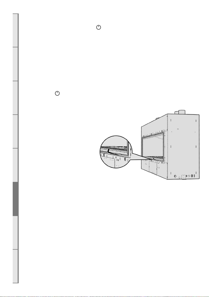
E10 Auxillary On/O button
The auxillary on/o button is
used to turn the replace on
without the Remote Control,
and also used for “teaching”
the replace to listen for new
remote controls. For information
on teaching a new remote
control, see section S4 of the
service manual at the end of this
document.
The auxillary On/O button is
accessed by using an allen-key
or thin object to poke through in
the location shown to the right.
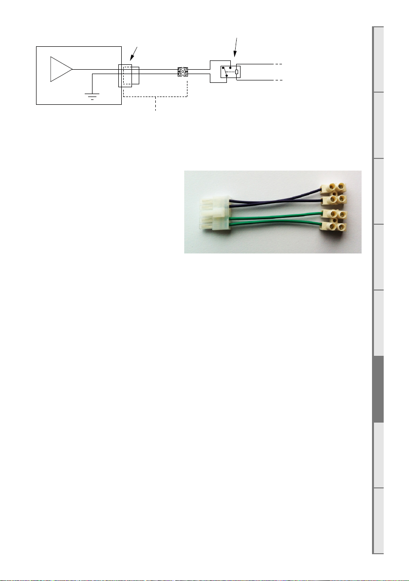
E11 Home Automation Setup
Escea D-Series replaces have a simple interface for connection to a home automation
system. Simply put this allows the replace to be woken up and started and then shut
down. The “Close to wake” connection shown is essentially taking one of the 3.3 volt DC
pins on the replace micro controller and pulling it down to ground. In order to isolate
the replace from the automaton system a relay needs to be used as shown. This allows
you to use any nominal voltage to drive the relay while keeping the replaces 3.3V supply
isolated.
34
Page 35
Fireplace
block supplied by Escea
Required relay
Connector
on fireplace
µ
+3.3VDC
Connector and terminal
Terminal block
From Automation system
Note: you will need to match the relay coil voltage with the voltage from your automaton
system.
The Home Automation connection can
be found in your replace accessory
pack and is shown to the right.
This connects to the replace via the
removable access panel in the bottom
right of the replace, as shown in
section C2.
Home Automation Operation:
Relay closed
The replace will start in a medium setting until it receives a signal from the remote control unit (up to 4 minutes). Once the remote has communicated with the replace it will
turn on and begin operating the replace thermostatically. The remote will use whatever
temperature the user has previously set and cannot be altered by the home automation
system. The replace will continue to operate while the relay is closed.
ACDEFGSERVICE
B
Note: If the replace cannot communicate with the remote controller within 10 minutes
of the relay contact closure then the replace will shut down and return to standby. The
remote controller is required to be operating within range of the replace for its safe
operation.
Relay open
If the replace was operating with a closed relay then upon opening the relay contacts
the replace will shut down and return the remote controller to its standby mode when
it next updates (up to 4 minutes). While the relay is open the replace will be in standby
mode and available for manual operation by the user.
35
Page 36
E12 Reinserting fuel bed and ceramic glass
A C D E F G SERVICE
B
Re-insert the 14 engine screws if removed.
Place the burners and Fuelbed Tray back into position.
If removed, place inspection panel back on.
At this stage you should relight the appliance to conrm correct ignition.
END OF SECTION E
By the end of this section, you should have:
□ The appliance installed in the cavity
□ The appliance xed to the cavity base and wall lining
□ The appliance plugged into a mains electricity supply
□ The appliance gas supply attached and pressure tested with all other gas appliances
running
36
Page 37
F
Finishing the Installation
F1 Crystalite, Coal, or Driftwood Fuel Bed Installation
If using the crystalight, coal, or driftwood fuel beds, rst place all the Crystallite/Coal pieces
in a single layer atop the Burners and Fuelbed Tray. Cover the entire area except for the
pilot shield, ensuring coverage right up to both glass windows and rear of rebox for single
sided.
If the Driftwood fuelbed style has been chosen, follow the above directions for placing the
Crystallite and then place the Driftwood pieces randomly atop the Crystallite layer. Ensure
the wood pieces are spread out across evenly and not over the pilot assembly.
Do not heap or mound any fuelbed. Continue onto following page >
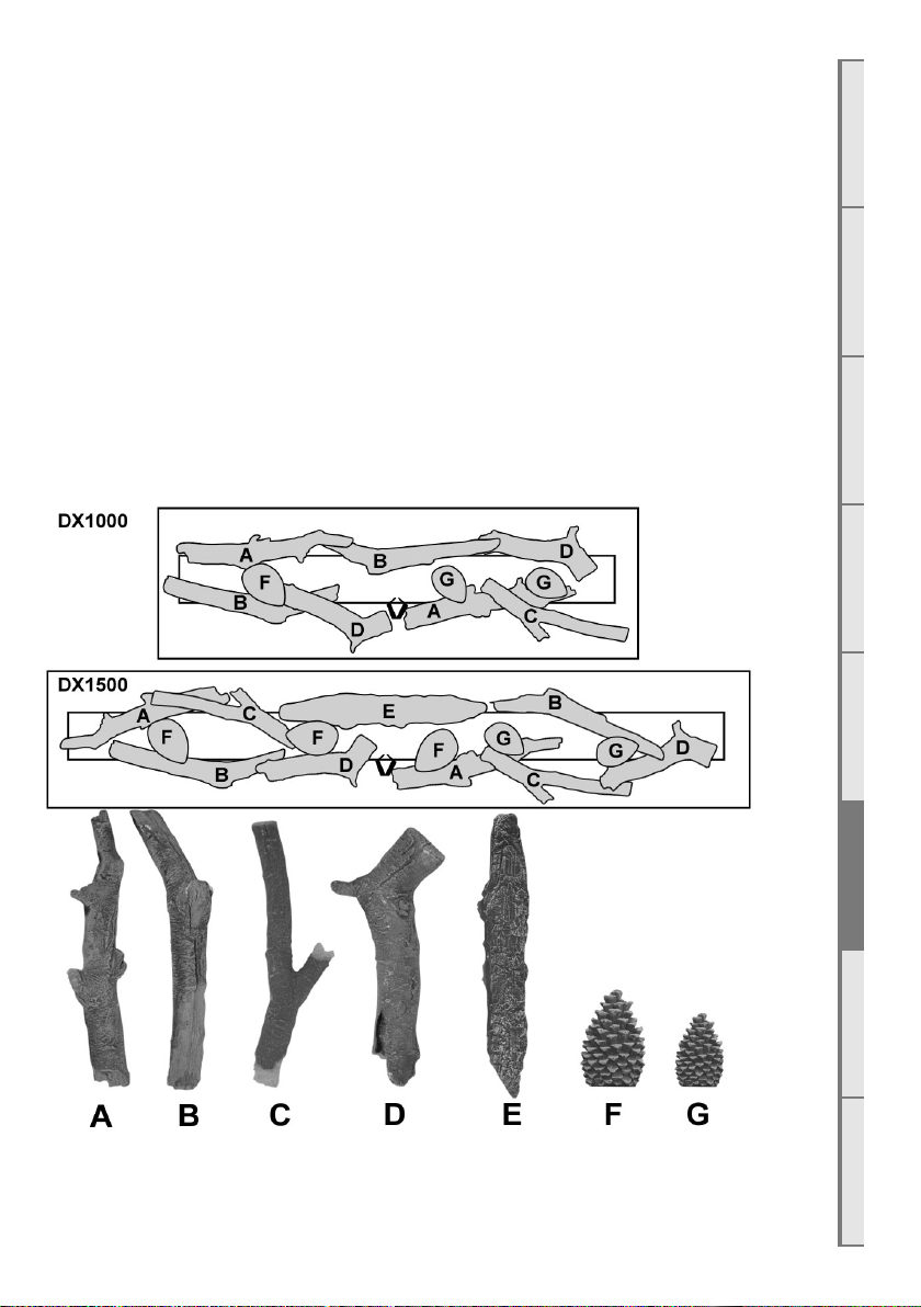
F2 Log and cone Fuel Bed (Woodland Selection)
If using the Logs and cones with Shale (chips) fuel bed, rst place the logs and cones in
the positions as shown below.
ACDEFGSERVICE
B
Once the logs and cones have been correctly positioned, scatter the Shale (chips) fuel bed
media evenly across the re base to cover as much area as possible without obstructing
the pilot ame.
37
Page 38
A C D E F G SERVICE
B
For the DX1000 you should use the 7x supplied 600ml bags of shale (chips), and for the
DX1500 you should use the 10x supplied bags.
Note: Improper positioning of any fuelbed media may create carbon build-up and will
alter the unit’s performance. Malfunctioning due to improper fuel media placement will
not be covered under warranty.
Reinstall the glass and retainer frame, being careful that the glass does not fall from the
frame. Tighten the bolts around the outside of the glass retainer until securely tted.
Do not over-tighten the glass retainer bolts. Just nip them up.
NOTE: If there is any residue left on the glass from the plastic wrap packaging
of the replace, it must be cleaned using any standard glass cleaner prior to
operation.
Note: If the glass gasket requires a replacement, call your nearest Escea agent who will
ensure the part is replaced with the correct type. In the event that the glass is broken by
impact, purchase the replacement from an authorised Escea agent only.
Conrm the appliance is working correctly by lighting it 2 or 3 times to ensure correct
operation & smooth ignition. Also conrm both ue and room duct fans are running correctly.
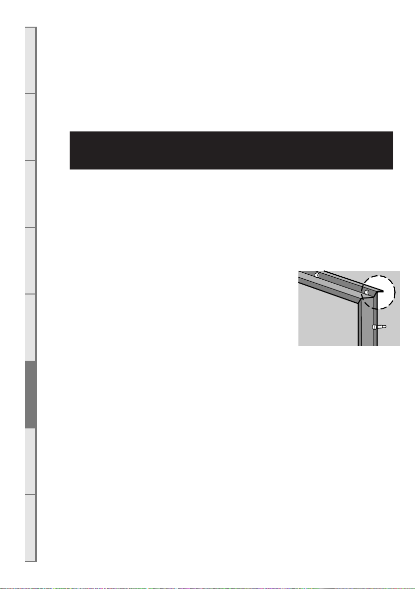
NOTE WHEN REPLACING THE GLASS:
When replacing the glass, note that the metal ange shown
to the right must be on top (not the bottom), or the glass will
not t correctly to the replace.
F3 Wall lining
Only after the above list is satised, can you commence with the nal wall linings.
The appliance and all corresponding ducting needs to be adequately covered (both sides
if double sided) to prevent plasterboard and building dust from entering the ducting
system during completion of the wall lining.
Wall lining cutout dimensions around the glass must be adhered to.
Please refer to section B8 for wall nishing dimensions surrounding glass.
Ensure the air inlet gap surrounding the glass is maintained. The glass frames must still be
able to be removed after wall linings installed.
38
Page 39
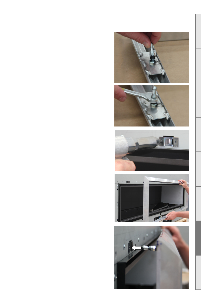
F4 Fitting the Fascia Panels
To avoid scratches or knocks to the fascia panels of this heater they must be tted at the
complete conclusion of the installation process, after wall linings are in place.
Note: Never ever rub the fascia.
Step 1: Ensure the plastic spacer is placed on
the thread of the studs.
Step 2: Screw and tighten the 4 studs with
spacers onto the back of the fascia.
Step 3: Rivet the 4x spring clips onto the chassis
of the appliance as shown
ACDEFGSERVICE
B
Step 4: After the 10-15mm thick wall has been
nished, the fascia clips onto the appliance as
shown. Note: wall linings larger than 10mm may
require the ‘Linear Trim’ available from your local
dealer to hide any exposed wall lining.
39
Page 40
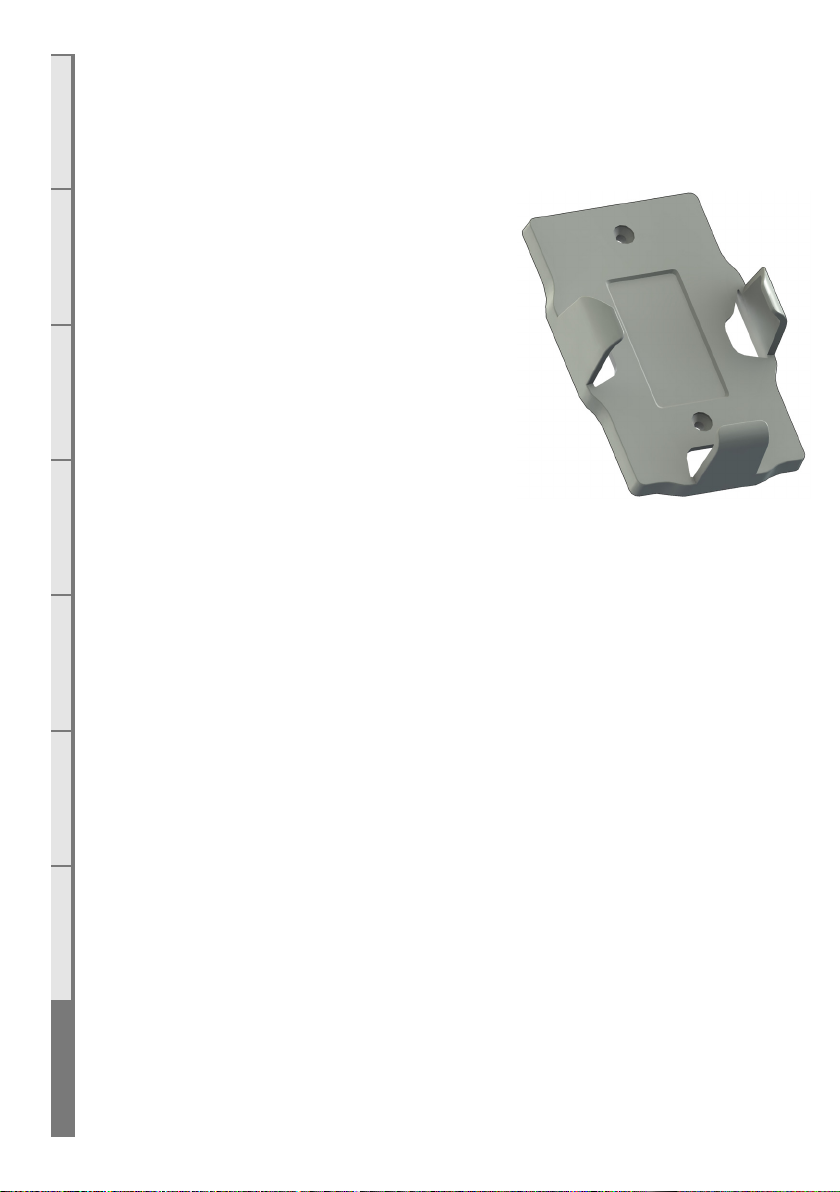
F5 Locating Wall Mount Cradle for Wireless Control
The appliance’s remote contains the thermostat that will sense the room temperature
A C D E F G SERVICE
B
and communicate this back to the heater via radio frequency.
A wall mount cradle has been provided for the wireless control and where possible the
control should be housed in this cradle.
The location of this cradle should be decided by
taking into account the following factors;
□ Simple, convenient access for the user
□ Away from air ow and drafts through the
room
□ The parts of the room that people are likely to
spend time
□ Away from direct sun light
□ A suitable distance away from the heater
□ Ideally 1.2m to 1.5m from the oor
The radio frequency signal will go through some
walls but for best results Escea suggest that the
cradle position is less than 10 metres away from
the heater.
The best height o the ground to locate the cradle is about chest height. This gives a
good average room temperature and easy access for the user.
Please ensure that cradle is screwed rmly onto the wall using the screws provided.
F6 Operating the Appliance
If you haven’t done so already, insert the supplied “AA” size batteries, being careful of the
polarity.
You should now see on the display of the remote the time showing “0:00”.
To turn the re on, press the “POWER” button once, and within a few seconds the appliance will begin its startup sequence.
NOTE: The appliance begins its startup with a 15 second pre-start purge, where the
combustion fan runs on its own to clear the rebox before it tries to ignite. During the
pre-purge the remote will alternately show the remote’s “Set” temperature and a rotating
segment indicator to show that the re is in start up mode and will try to ignite.
When the appliance has lit, set the room temperature by pressing the ‘plus’ or ‘minus’
buttons repeatedly until the display is showing the desired temperature. The remote will
then revert back to the ‘current’ room temperature 30 seconds after making the change.
Run the appliance on full for an hour with the windows and doors open in the dwelling.
This will ensure any running-in smells have the chance to dissipate.
The appliance is turned o by pressing the “POWER” button once more. The remote will
display the time only.
40
Page 41
Run the appliance again and check the operation of the thermostat by increasing and reducing the set temperature. Check the Flame Eect function and the Fan Boost functions
work correctly.
For further operation instructions please refer to the User Guide.
Final checklist
□ Run the appliance on full for an hour with the doors & windows open
□ Dwelling owner shown how to operate the appliance correctly
□ Warranty card lled in with installer details and appliance serial number
□ User Guide made available for dwelling owner
□ Plumbing Industry Commission Compliance Certicate given to dwelling owner
ACDEFGSERVICE
B
Page 42
F7 Normal Operating Sounds and Smells
Note: Each time the re is lit from cold the glass may fog up with condensation. This is normal and the
A C D E F G SERVICE
condensation will disappear within a few minutes once the glass heats up.
Sounds
It is possible that you will hear some sounds from your gas appliance. This is perfectly
normal due to the fact that there various types of materials used within your appliance.
Listed below are some examples. These are all normal operating sounds and should not
B
be considered as defects in your appliance.
Fan:
Escea gas appliances use electric fans to push heated air into the room. It is not unusual
for the fan to make a “whirring” sound when ON. This sound will increase or decrease in
volume depending on the speed setting of your fan.
Gas Control Valve:
As the gas control valves turn ON and OFF, a dull clicking sound may be audible, this is
the normal operation of a valve. When the re is switched o after being run for a while,
there may be popping and uttering noises as the residual gas in the burners burns away.
These are normal and should be no cause for concern.
Unit Body/Firebox:
Dierent types and thicknesses of steel will expand and contract at dierent rates resulting in some “cracking” and “ticking” sounds being heard throughout the heating and cool
down processes.
Smells
The rst few times the unit is operated, the unit may release an odour and the ames will
appear orange caused by the curing of the paint, the burning o of the starch in the gas
logs and the oils in the metal. This is a temporary curing process which will disappear
with use.
A deposit on the inside of the glass, caused by the starch in the logs, may appear as a
build up after several uses. If this lm is not removed, it will bake on and may become
dicult to remove. When the glass is cold, remove it (see section E5) and clean the inside
with a non-abrasive cleaner.
DO NOT ATTEMPT TO CLEAN THE GLASS WHILE IT IS HOT.
UNDER NORMAL USE, NEVER OPERATE THE UNIT WITH THE GLASS REMOVED.
END OF SECTION F
By the end of this section, you should have:
□ A completely tted fascia
□ The remote control mounted on its cradle on a wall
□ Operated the re and veried that it lights reliably and safely
□ Run the appliance on full for an hour with the doors & windows open
□ Checked the operation of the thermostat, Flame Eect & Fan Boost functions
42
Page 43
G
Installation Checklist
Go through the following checklist to ensure you have installed the appliance correctly
□ Correctly sized cavity to suit your fascia and ue conguration
□ Correct clearances to combustibles and mantles around the fascia
□ An electrical isolating switch to the appliance, accessible after nished installation
□ Correctly sized gas supply with a pressure test point, ensuring adequate supply with
all other gas appliances in the dwelling running
□ A weather-tight installed Horizontal or Vertical Powerue Terminal with clearance as
specied by AS/NZ5601.1
□ If chosen, reasonable access to the outside face of the Horizontal Powerue Wall Ter-
minal for maintenance purposes and ue attached to the rear of the Horizontal Powerue
Wall Terminal leading back to the appliance (and similar for Vertical Powerue Terminals)
□ The electrical cable from the Powerue Terminal attached correctly and run back to
the appliance cavity in an electrically safe manner
□ The appliance xed to the cavity base
□ The appliance plugged into a mains electricity supply
□ All gas joints and pressure points leak tested, and suitable leak detection solution and
drop tests completed on gas pipework
□ Fuel bed correctly installed
□ Glass correctly tted
□ Operated the re and veried that it lights reliably and safely
□ Appliance functions checked, including thermostat operation, Flame Eect and Fan
Boost
□ Data label marked up with correct gas type, and dated by installer if converted during
installation
ACDEFGSERVICE
B
Page 44
Service Manual
S
A C D E F G SERVICE
IMPORTANT:
• This appliance must be serviced every 12 months.
• Any service operation should be carried out only by a suitably qualied and
trained person.
B
S1 Annual service procedure
• Gas and electricity supply MUST be isolated before any service operation is
carried out on this appliance.
• This manual should be left with the appliance.
• DO NOT MODIFY THIS APPLIANCE.
□ Isolate power and gas supply to re.
□ Remove front glass and clean inside of glass.
□ Remove fuel bed and brush o any soot.
□ Clean electrode and pilot hood of any carbon build up and ensure correct
gaps between electrode and pilot hood
□ Remove burners and blow compressed air through the burner ports.
□ Remove jets and clean injector hole with solvent.
□ Vacuum any dust from the cavity that houses the fan and from the underside
of the re box around the valve and solenoids.
□ Test all joints for gas tightness.
□ Reassemble heater and check that operating pressure is correct.
□ Check glass sealing tape and replace if necessary.
□ Check to make sure that ue system is intact and not in any way blocked.
□ Trial heater with several start/stop cycles and trial fan-boost, ame eect only
and thermostat modes to ensure that all modes function correctly.
To access the product Dataplate, rst remove the replace glass, any fuelbed media, the
burners and the rebox base. An access panel is located to the side of the bottom of the
rebox, the dataplate is located underneath this access panel.
44
Page 45
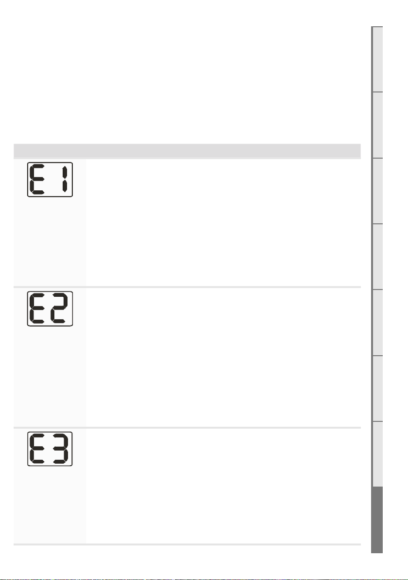
S2 Error Codes
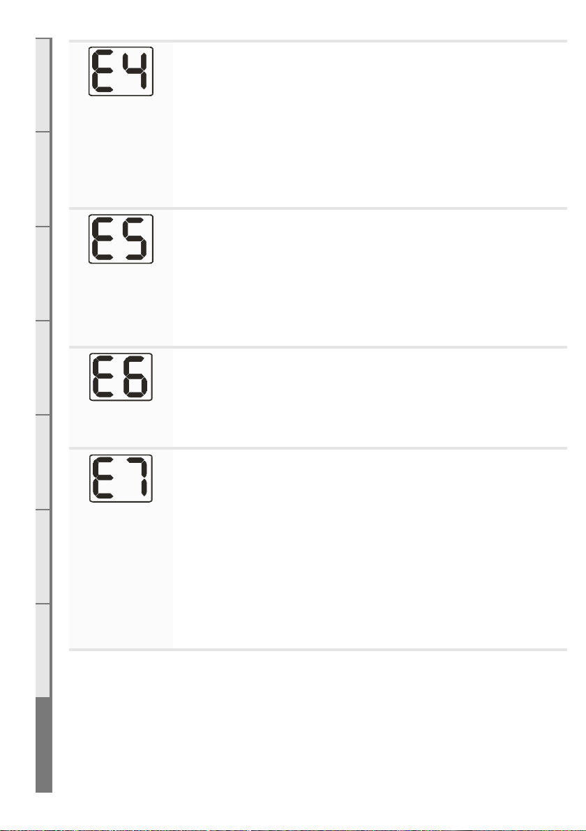
This gas re has been designed to show error codes to help explain and identify any fault
situation that occurs. These codes will appear on the wireless remote control in the form
of a large letter “E” with a number beside it. Codes can normally be reset by turning the
heater o then on again at the wall.
The following table shows what each code means and possible ways to rectify the situation. In the case of persistent or repeated shutdown errors, action must be taken immediately to nd and repair the fault.
Error Code Suggested action
• Excess lint and dust build-up on the PCB / Controller.
• Possibly fascia panels installed incorrectly resulting in restricted air
ow.
Electronics Over
Temp
Flame Failure or
Power Flue trip
Appliance Over
Temperature
Sensor Trip
• Ensure correct gaps are present around glass.
• Room air fans may be slowed or stalled. Remove rebox, check that
fans are plugged in, cleaned, and free turning.
• (DX only) check that the duct fan is not reversed and blowing “into”
the replace instead of out from the replace.
Note: This error has a permanent lock out and will require the unit to be
reset after the initial error (turning the power to the re o “at the wall”
then on again after a few seconds).
The re has tried to light three times and failed.
• Check gas supply and check other gas appliances to see if they are
aected. If you have two separate LPG cylinders, switch over to the
full bottle or contact your gas supplier. You may need to retry igniting the re a few times after re-establishing gas supply.
• Check correct gas pressure to the appliance with all other appliances
running.
• Check the electrode placement in relation to the pilot ame. Ensure
it is well enveloped in ame as per the diagram in the installation
instructions. Ensure no small coals have dropped onto the ignition
electrodes between the burners.
• Ensure the electrode is not contacting any metalwork including the
burners and has the correct air gap.
The bimetallic snap disk mounted on the exhaust collector box has
tripped. The possible causes for this could include:
• Possibly fascia panels installed incorrectly resulting in restricted air
ow.
• Room air fans may be slowed or stalled. Check that fans are plugged
in, cleaned, and free turning
• The regulator being set too high resulting in excess heat build-up.
• The inlet ue not being connected and the appliance drawing warm
air from the cavity. Check ues are securely connected at both ends.
• Incorrect Jetting
ACDEFGSERVICE
B
Page 46
A C D E F G SERVICE
B
Valve Solenoid
Check Failure
Remote Cannot
communicate
with re
Duct Air Over-
temp
The valve solenoids have failed the pre-ignition test. This is to detect a
faulty valve solenoid. However, it is possible a wire has dislodged.
• Check that the connections to each solenoid are secure and in place.
It may be that the connections on the ends of the wires need to be
tightened a little (e.g. with a pair of pliers) to ensure a robust connection to the valve terminal.
• Disconnect and reconnect the rebox connectors ensuring they are
rmly pushed into place.
• It could also be that one of the solenoids on the valve inside the re
has failed. If this is the case the valve will need to be replaced.
The remote cannot communicate with the re. Reasons for this could
include:
• The re being turned o “at the wall” i.e. a loss of power to the re or
the remote is outside of its eective radio frequency range (too far
away from the re). Typical remote range is 1m to 10m.
• Ensure there is power to the re by pressing the auxiliary on/o (red)
button on the re, then press the on/o button on the remote to
clear the error.
The hot air duct temperature sensor has detected excessive heat at the
duct outlet.
• Ensure that there are at least TWO air vents installed and open in the
same room as the replace
• Ensure the duct fan is operating when the replace is running. If not
check that the duct fan cord is plugged into the replace.
Combustion Air
Flow Error
46
• Check the the ue fan is plugged in at both ends and operating
correctly.
• Check whether the pressure switch is activating at startup (there is
an orange indicator LED in the control tray). If not check the pressure
switch electrical connection is correct.
• Check that the hoses are connected at both ends. Ensure the hoses
are not kinked.
• Ensure the pressure switch is mounted vertically and the diaphragm
is operational. The grey hose should be connected to the low pressure port and the translucent to the high pressure port
• Check that both ues are securely connected at both ends to the
appliance and the powerue wall terminal and that the ue is not
damaged
Page 47
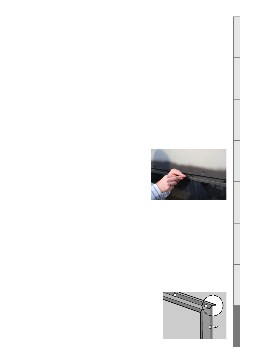
S3 Cleaning the Fuel bed and Glass
ALWAYS USE GLOVES WHEN HANDLING THE FASCIA AND GLASS.
NEVER RUB THE FASCIA.
The outside of the fascias must only be cleaned with a clean damp cloth, dry o after
cleaning. The high temp silver powder coating that is used on Escea fascia parts contains
certain amounts of aluminium that when rubbed too hard will oxidise leaving a black
smudge that cannot be removed. Always clean when cold.
This is a service procedure that will need to be carried out whenever soot builds up on
fuelbeds and/or inside of glass.
If soot build up becomes excessive or regular then one of the following actions may be
required;
• Reset gas pressure, pressure may be too high;
• Reposition fuelbed, check with specic fuelbed instructions for details;
• Clear any blockage from primary aeration port of burner;
• Check ue tube is not damaged or disconnected.
• Check exhaust fan is operating and cowl is not blocked in any way.
Step 1: Remove fascia panel (if tted) by pulling it from
the wall.
Step 2: Removing the Glass
Using the supplied 3mm Allan Key (hex drive) unscrew
the bolts around the glass retainer.
Take care that the glass and frame does not fall forward
at this stage. Pull the top of the frame toward you slightly and lift the glass and frame out
and away from the re. Ensure to hold on the glass, and take care that the glass does not
fall from the frame. Place the glass & frame carefully aside - This is a two person lift.
ACDEFGSERVICE
B
Step 3: Take out fuel bed and gently clean away any soot from fuelbed with a soft hearth
brush. The burner tops and fuel media tray can be vacuumed to remove any excess material.
Step 4: Clean the inside and outside of glass with normal glass cleaning products. Use a
CLEAN DRY cloth only. Stubborn marks may be cleaned with a ceramic glass cleaner.
Step 5: Reinstate fuel media and glass and test run heater.
NOTE WHEN REPLACING THE GLASS:
When replacing the glass, note that the metal ange shown
to the right must be on top (not the bottom), or the glass will
not t correctly to the replace.
Page 48
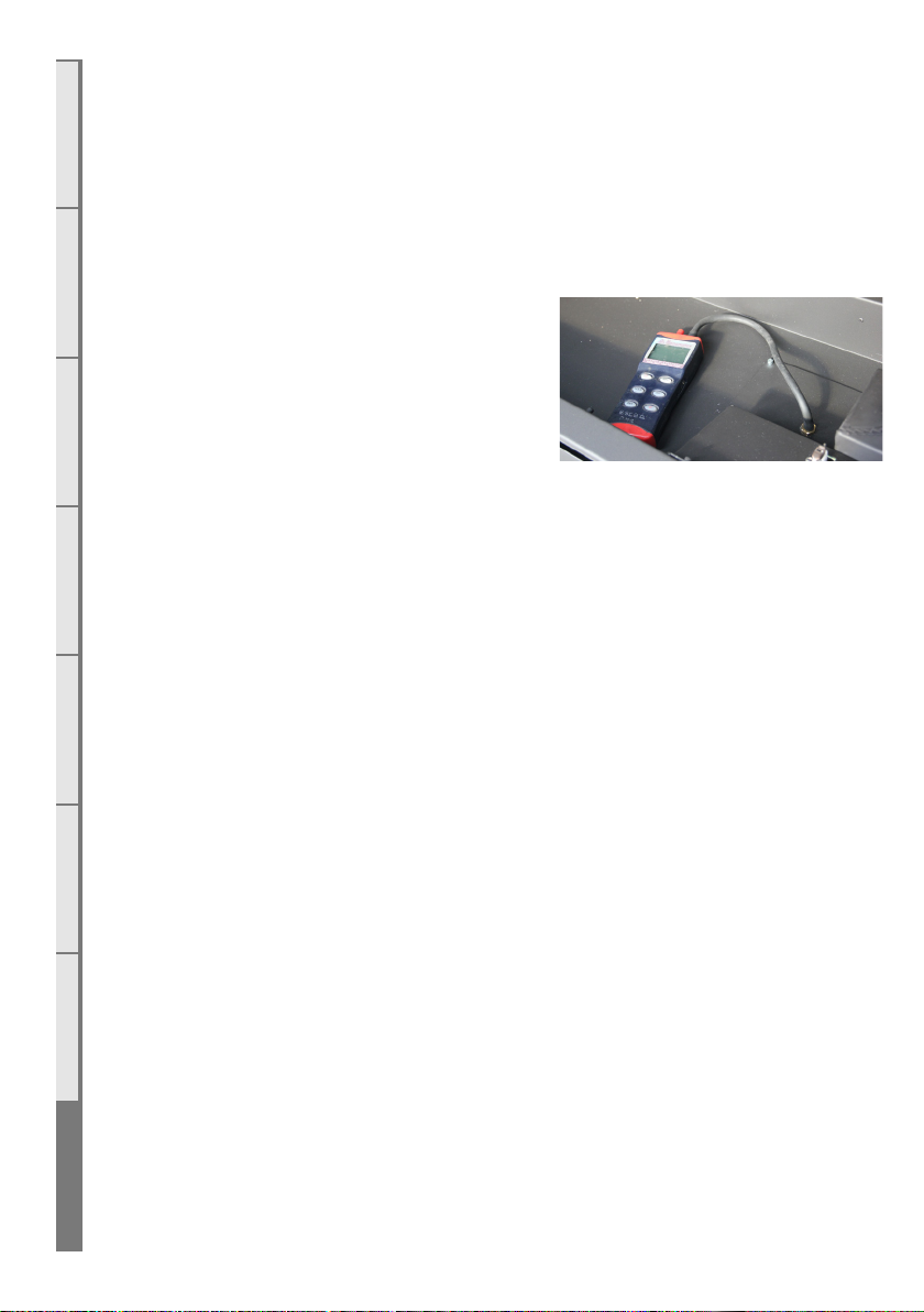
S4 Checking Operating Pressure
A C D E F G SERVICE
B
WARNING: The regulator that is supplied with the re MUST NOT BE REMOVED.
Removal of the regulator, or replacing it with one not intended for use with an Escea re,
will void the limited appliance warranty.
By law, the original installer has supplied a test point prior to the appliance. With all
gas appliances within the house running on full, including this DX1500, check the inlet
pressure upstream of the appliance. It must conform with the table in section E8.
To check the operating pressure, with one burner
removed only place your Manometer hose onto
the jet spigot as shown. Ensure you place the
manometer well away from the other burner as
this will get hot.
48
Page 49
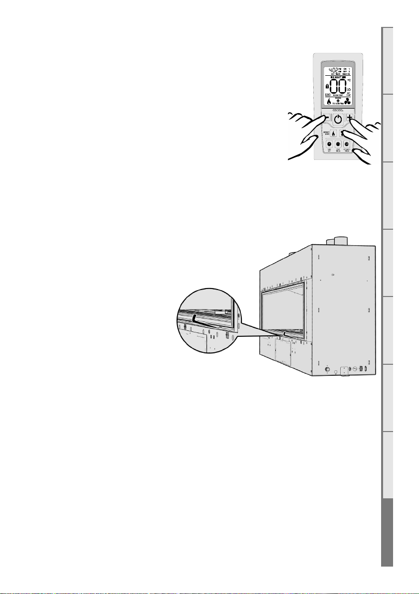
S5 Replacing a Remote Control
If the wireless control becomes lost or damaged, a new one can
be ordered from any Escea retail agent. When you have the new
remote, the following procedure needs to be followed to “teach”
the remote to only communicate with that re.
1. Ensure the re and remote are set to “O ” (only the time is
displayed on the remote).
2. While the remote is in its “OFF” mode with only the time showing
on the display, press the MINUS, PLUS and FAN BOOST buttons
simultaneously (as shown right) until the characters “03” light up on
the display. Release the buttons and the remote will count down and display “GO”. The
screen will then display all characters and should be reading 00. This will put the remote
into test mode.
Note: if the digits start counting then the remote is already paired.
3. Press and hold the – (minus) button until the two large temperature digits reading 00
start to ash slowly. Release the –
(minus) button. The remote control
is now ready to be addressed to the
re.
4. Press and hold the red auxiliary
on/o button on the replace for a
minimum of ten seconds, or until the
two large temperature digits start
counting upwards from 00 to 99
repeatedly.
ACDEFGSERVICE
B
Note: Pressing the red auxiliary
button on/o button will start the
re. Once the remote control is counting the re can be turned o by pressing the red
auxiliary button again.
5. Press the large power button in the middle of the remote control to exit the test mode
and return to normal operation. The remote should only be displaying the time. Check
the re will start using the remote control by pressing the large power button. Turn it o
again using the remote control.
6. The re is now re-addressed to the remote control.
Page 50
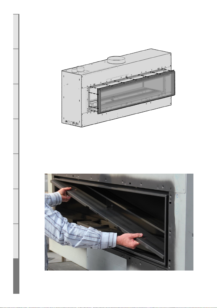
S6 Replacing the burners
A C D E F G SERVICE
B
If a fascia is tted, remove this rst.
Using the supplied 3mm Allen Key (hex drive) remove the bolts around the glass retainer
ensuring that the glass does not fall forward.
Pull the top of the frame toward you slightly and lift the glass and frame out and away
from the re. Place the glass & frame carefully aside.
Remove all of the fuelbed, taking care not to damage any logs or media.
Remove the Fuelbed tray from the re box, by lifting one end up into the top corner and
then out towards you. Take care not to scratch the rebox paint and lift out the burners.
50
Page 51
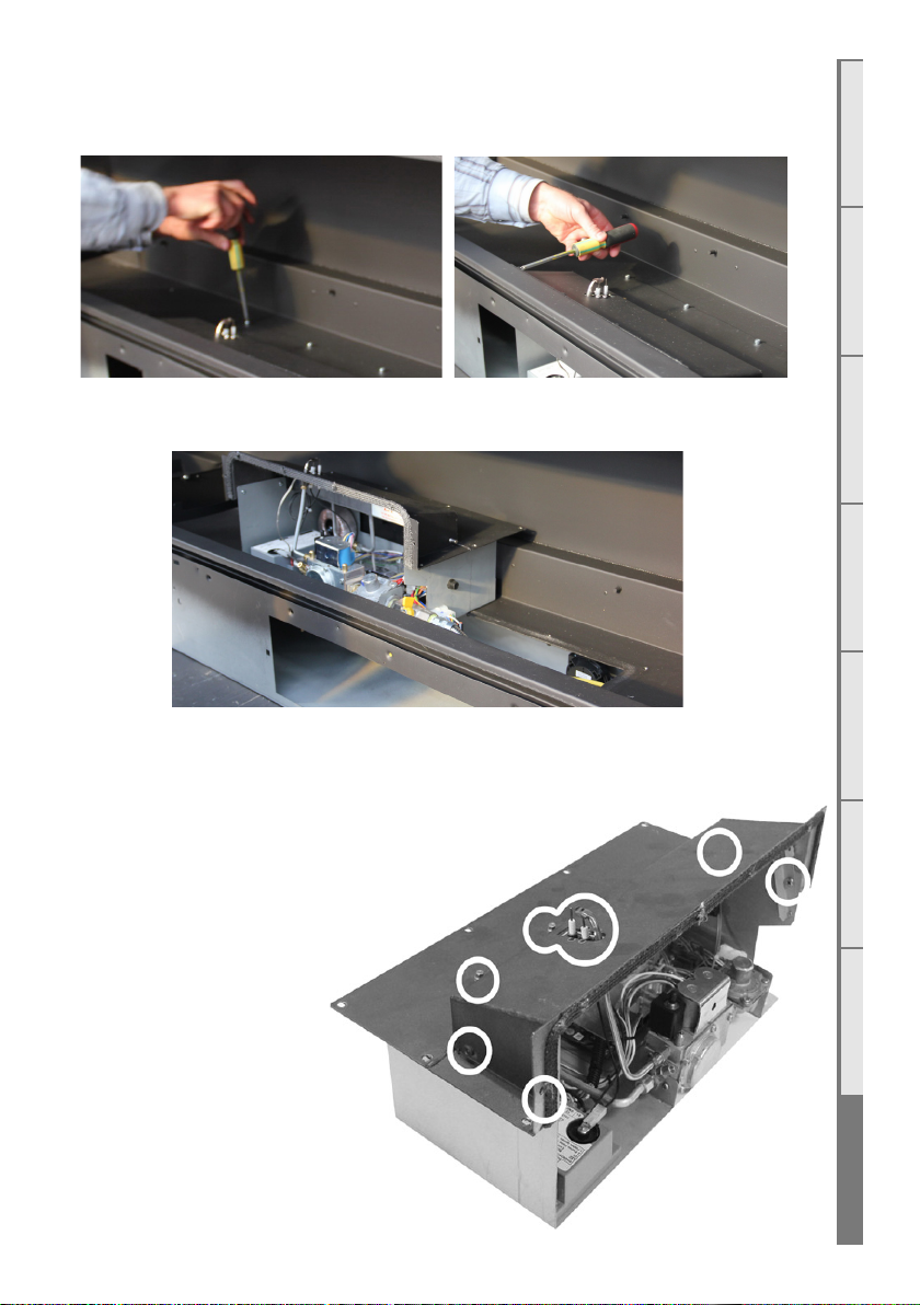
S7 Accessing the control tray
Remove the screws in the bottom and the inner side of the rebox as per shown.
Remove the ‘engine’ by lifting up and to the left. This is still connected internally to the
gas hose and power cables. Place engine just to the left within rebox as shown.
ACDEFGSERVICE
B
S8 Removing the Circuit Board
Step 1: Remove the Pilot
cover and 2 jets circled to the
right.
Step 2: Remove the 4 screws
circled to the right from the
inside and lift the cover upwards to remove it. This will
give you easier access to the
circuit board.
Page 52
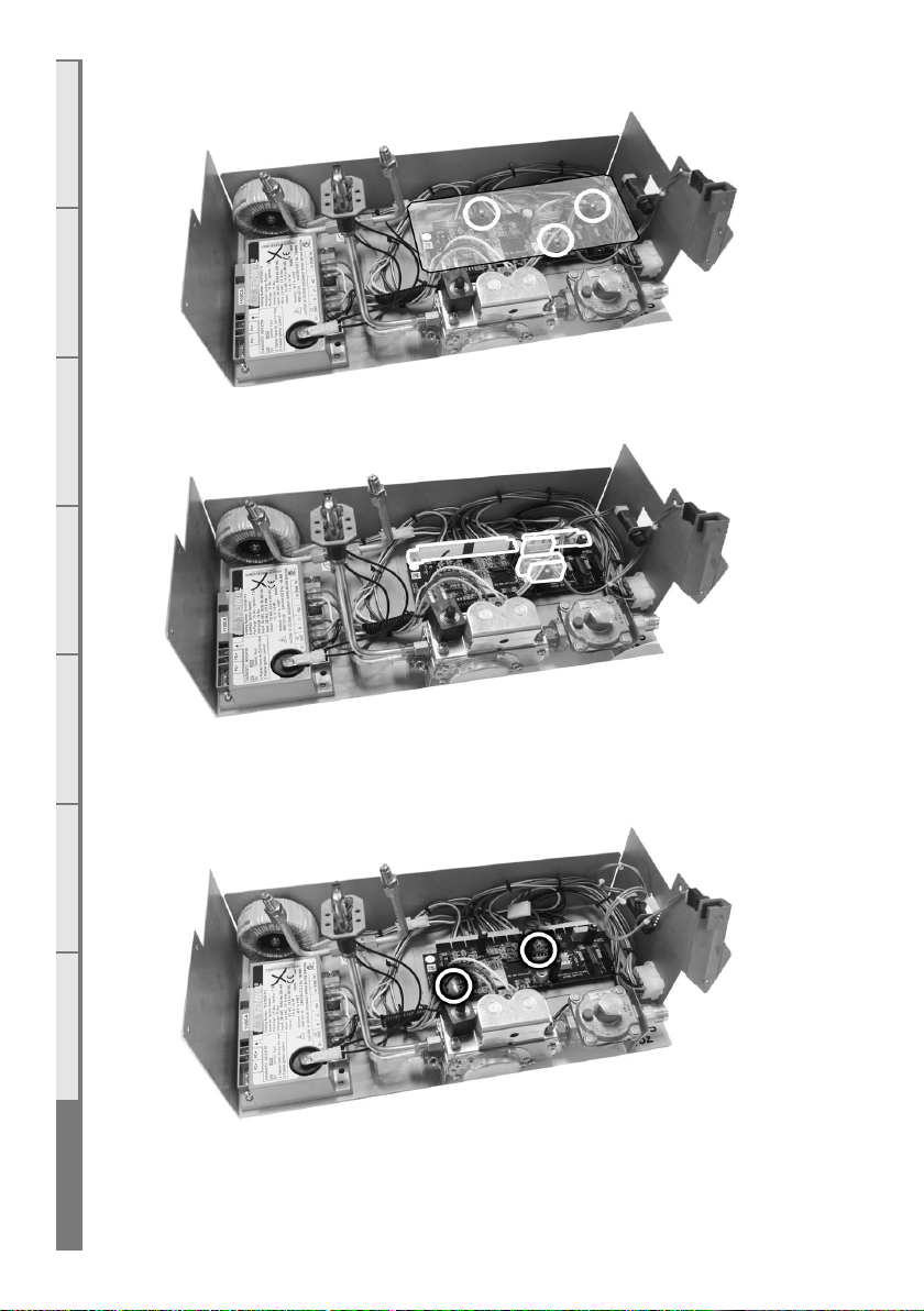
A C D E F G SERVICE
B
Step 3: Remove the clear plastic insulation cover from ontop of the circuit board by
removing the screws circled below.
Step 4: Remove all 5 connections to the circuit board as highlighted below.
Step 5: Remove any screws securing the circuit board to the base and remove the circuit
board. Take care that the black spacers underneath the board stay in place until the board
is replaced.
Replace the circuit board (if applicable) and reverse these steps to re-assemble the
Engine.
52
Page 53
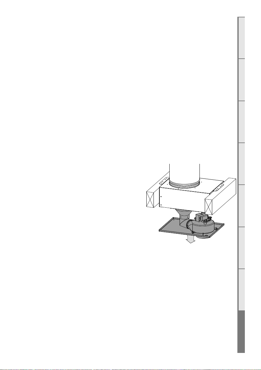
S9 Servicing the Horizontal / Vertical Powerue
Ensure the power to the Powerue is o by disconnecting the power to the appliance
inside. If the appliance has been running, allow the Powerue to cool before attempting
to service it.
Servicing a horizontal Powerue:
If the Powerue needs servicing, the fan can be accessed from the outside of the installation for Horizontal termination, and accessed from within the roof space for Vertical
termination.
Undo the screws on the outside of the Powerue box and seperate the two parts, giving
you access to the fan inside.
Removing this plate gives complete access to the fan for servicing or replacement. Check
that all the seals are still intact. Check the fan electrical terminals, motor and impellor are
not corroded. Ensure there is no signs of leakage in or around the terminal.
When reassembling the powerue, line up the round silicon grommets with the outlet
tube of the fan and push the cowl back into place. Ensure all seals are still in place and
replace all of the screws to hold the cowl in the correct position.
Servicing a vertical Powerue:
If the vertical Powerue needs servicing the fan can
be accessed without disturbing the nal twin walled
ue length or roof terminal.
To gain access to the fan and electrical terminals
remove the eight screws that hold the base of the
Powerue to the lid, making sure to support the
base while removing the screws.
Note: When inspecting or working on the Powerue
take care not to damage the two exible ue pipes
that connect to the Powerue base.
ACDEFGSERVICE
B
Once the base has been removed clean away any dust or debris found and check that the
fan electrical terminals, motor and impellor are not corroded. Also check for signs of leakage in or around the Powerue.
When reassembling the Powerue support the base under the lid and replace the 8
securing screws. After assembly check that the two exible ue pipes are sealed and not
damaged and that the twin walled nal ue length and roof terminal are still sealed.
Note : Take care not to trap any wires between the base and lid of the Powerue when
reassembling.
Page 54
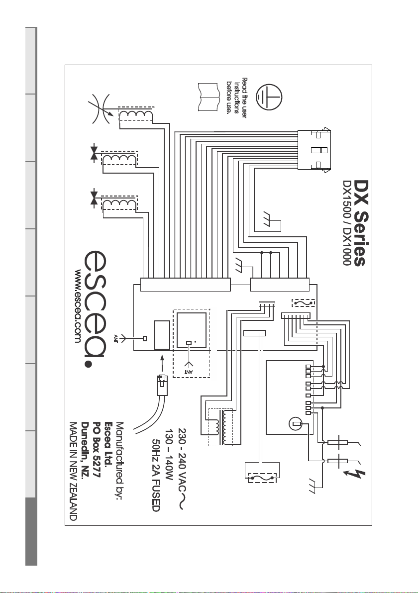
S10 Wiring Diagram
CON6
CON10
CON9
TRANSFORMER
240VAC - 18VAC
ISOLATING
VALVE & PILOT
MAIN BURNER
WIFI
MODULE
FLAME SAFETY CONTROLLER
FENWAL 35-61
i
-
con
OPTIONALWIRELESS NETWORK
Part No. 620278
W
V2
L
1
R
IND
PSW
V1
GND
S1
SPARK
ELECTRODE
ESCEA
CONTROLLER
MAINS FUSE (2A)
NETWORK
(RJ45)
NETWORK CABLE
FLUE FAN
FUSE (1.5A)
ROOM FAN
FLUE FAN
MAIN BURNER
FLOW CONTROL
i
A
N
N
N
E
Main Tray/Chassis
Connector (CN1)
Controller and Valve
Tray Schematic
A C D E F G SERVICE
B
54
Page 55
ACDEFGSERVICE
B
 Loading...