

Page 1
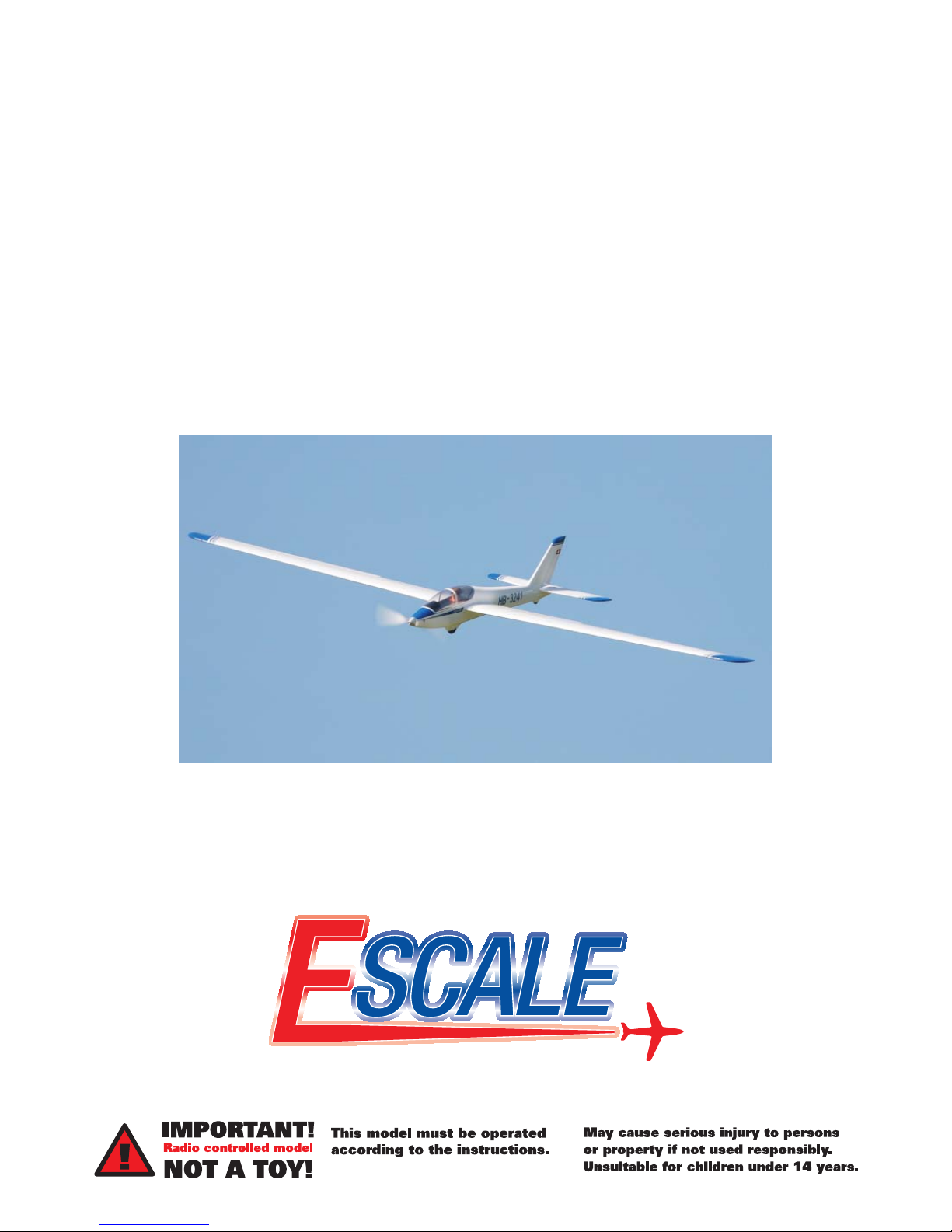
FOX
ARF Aerobatic Electric Glider with
Fibreglass Fuselage & Sheeted Foam Wings
ASSEMBLY INSTRUCTIONS
SPECIFICATIONS:
Wingspan: 2800mm
Length: 1360mm
Weight (inc. battery): 3600g
Page 2
2 EScale Fox - Instruction Manual
VITAL SAFETY INFO
CAUTION! The Fox glider is not a toy.
It can cause injury to persons/animals and/or property if
not used correctly. It is unsuitable for beginners or persons
under the age of 14. You should take care and observe
the principles of safety when fl ying this model. In the
UK, we recommend you observe the British Model Flying
Association (BMFA) safety code at all times, which can be
found at the following address: http://www.bfma.org
In Australia, please contact your hobby retailer or the Model
Aircraft Association of Australia (MAAA).
YOU ASSUME ALL RISK.
This is not a beginners kit. Before beginning construction,
please read this document thoroughly and familiarize
yourself with the construction sequence.
If any information in this manual is unclear, please contact
your retailer for help.
After reading this manual store it in a safe place for future
reference.
This kit is not suitable for beginners.
Intermediate to advanced skills are required to build it.
Intermediate to advanced R/C fl ying skills are required
to fl y it.
ABOUT THE FLYING AREA
REQUIRED
Only fl y in large open spaces that are approved for R/C model
fl ying and that are away from people, animals, buildings,
power lines, water or trees.
CONTENTS
weee disposal .................................................................. 2
Vital safety info ...............................................................2
About the fl ying area required ...................................... 2
Guarantee/warranty ........................................................ 2
Kit contents ....................................................................... 3
Fitting aileron servos to wings ..................................... 4
Fitting optional spoilers/airbrakes .............................. 6
Fitting servos & optional motor, folding prop & ESC 8
Fitting horizontal stabilizer & rudder ......................... 10
Fitting canopy frame and canopy ............................... 12
Fitting and securing wings ..........................................14
Checking C of G & control throws .............................. 15
GUARANTEE/WARRANTY
J. Perkins Distribution Ltd guarantee this prod uct to be free of manufacturing and assembly defects for a period of one year from
time of purchase and Model Engines (Aust.) Pty. Ltd. is for 30 days. This does not affect your statutory rights. This warranty is not
valid for any damage or subsequent damage arising as a result of a crash, misuse, modifi cation or for damage or consequential
damage arising as a result of failure to observe the procedures outlined in this man u al. Operation of this model is carried out
entirely at the risk of the operator. Please note that, whilst every effort is made to ensure the accuracy of instructions and material
included with this product, mistakes can occur and neither J. Perkins Distribution Ltd/Model Engines (Aust.) Pty. Ltd. nor it’s
distributors will be held liable for any loss or damage arising from the use of this model or for any loss or damage arising from
omissions or inaccuracies in the associated instructions or materials included with this product.
We reserve the right to modify the design of this product, contents and manuals without prior notifi cation.
© 2010 J Perkins Distribution Ltd, Lenham, Kent, UK ME17 2DL. www.jperkinsdistribution.co.uk
Model Engines (Aust.) Pty. Ltd., Noble Park, Victoria 3174, Australia. www.modelengines.com.au.
All rights reserved. E&OE.
WEEE DISPOSAL
Do not dispose of this product with other household
waste. Instead, it is your responsibility to dispose of
your waste equipment by handing it over to a designated
collection point for the recycling of waste electrical
and electronic equipment. The separate collection and
recycling of your waste equipment at the time of disposal
will help to conserve natural resources and ensure that
it is recycled in a manner that protects human health and
the environment. For more information about where you
can drop off your waste equipment for recycling, please
contact your local council, your household waste disposal
service or the shop where you purchased the product.
Page 3
3EScale Fox - Instruction Manual
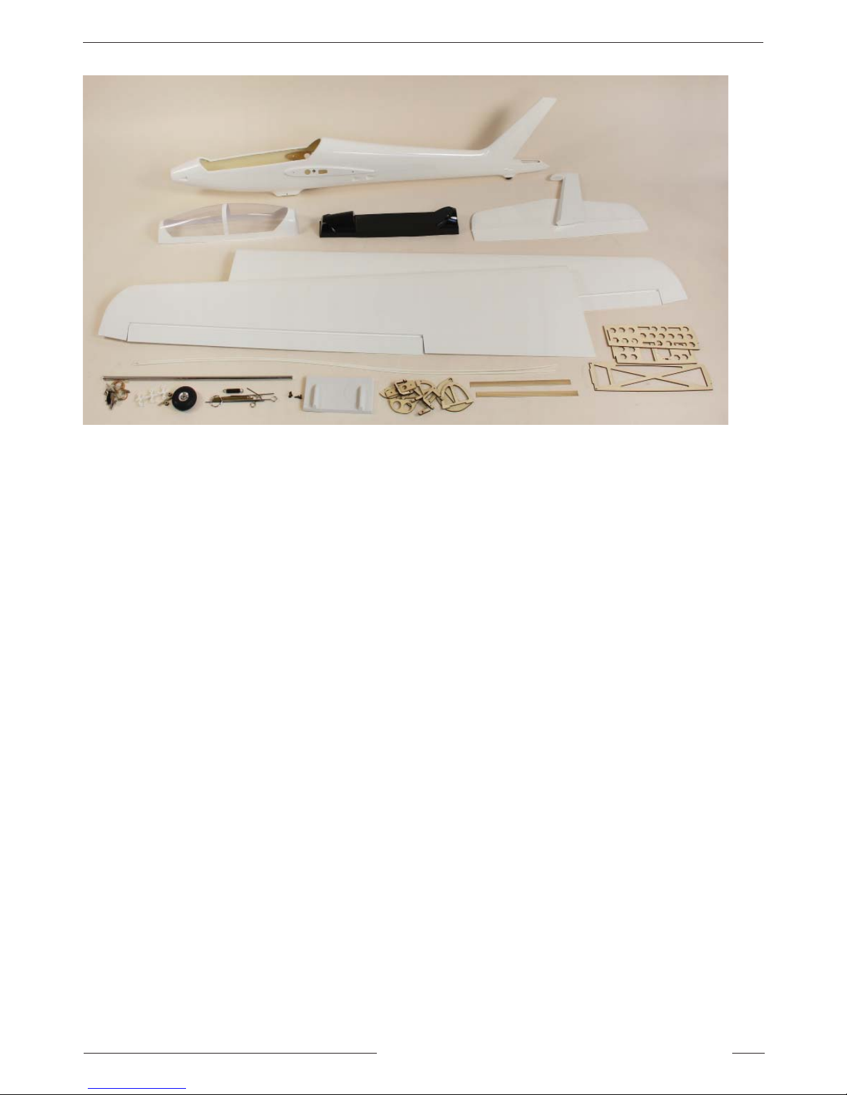
KIT CONTENTS
CONTENTS LIST
Gel Coat pre-fi nished fi breglass fuselage
Film covered, balsa skinned, foam wings
Film covered, balsa skinned, rudder
Film covered, built up horizontal stabilizer and solid balsa elevator
Canopy set
Cockpit set
Front wheel set
Screw set
Hinges
Pushrods, control horns and Clevises
Steel wing joiner
Rubber bands and hooks
Servo Covers
ADDITIONAL ITEMS REQUIRED
Part No. JPFOX10 FOX Brushless Motor C35-26-1000kv
Part No. JPFOX12 FOX 14X8 FOLDING PROPELLER with 5mm HUB and 41mm SPINNER
Part No. 4406305 ELECTRIC AIR BRAKE SYSTEM (2) Electric ELF Spoilers/Airbrakes (left/right pair)
2x wing servos. Hitec HS-125MG or HS-5125MG digital or 7720465 S/TEC Micro D BB M/Gear 28g digital servo
2x mini servos. Hitec HS-245MG or HS-5245MG digital or 7720413 S/TEC Park Flyer HPX BB servo
2x 600mm servo extention leads
Pilot fi gure
60 Amp ESC (Minimum)
11.1V 2200mAh LiPo 20C Battery (Minimum) 3200mAh recommended
Battery/ESC connectors
Minimum 5 channel computer radio with mixing
Minimum 5 channel receiver
15min Epoxy, thin fl exible CA and assorted tools (e.g. spanners, screw drivers, drills, hobby knife)
Page 4
4 EScale Fox - Instruction Manual
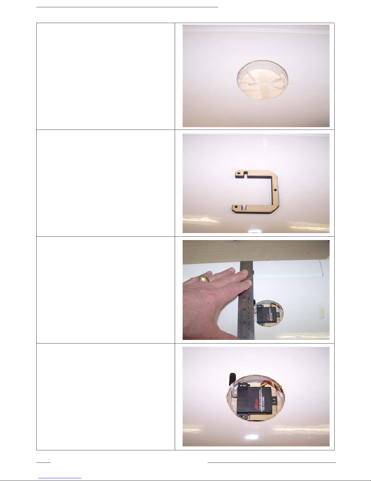
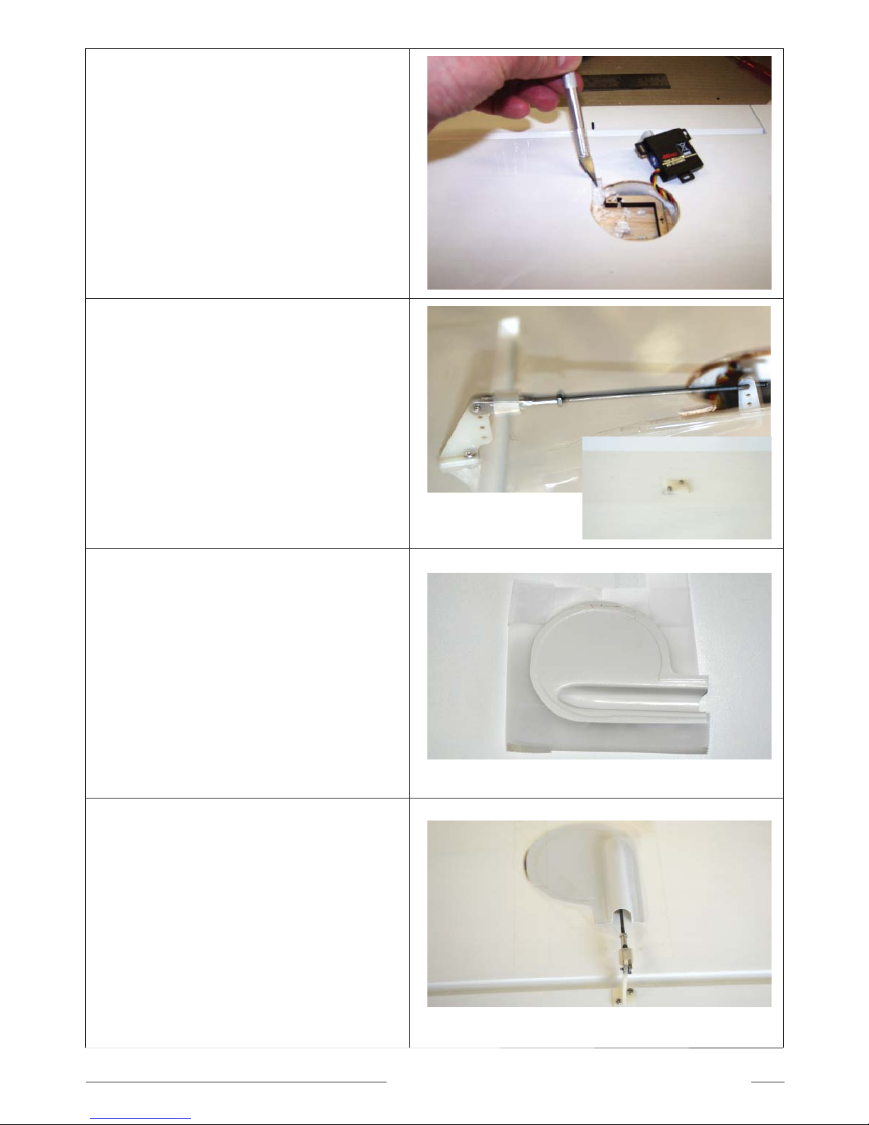
1. Locate the servo holes in the wings and
carefully remove the fi lm covering using a
new blade in your hobby knife.
2. Trial fi t your servo to the servo frame and the
servo frame in the hole. Adjust if necessary
Connect the servo to a servo programmer or
receiver to set for neutral position.
Attach a 600mm servo extension lead to servo
and use the cord provided to pull the servo
lead through the wing.
3. Use a ruler or straight edge to establish a
line for the control rod. Make sure the line
is perpendicular to the hinge line as shown.
Gently mark the horn position with a felt tip
pen.
4. Also mark the area to be removed to allow
the servo horn to rotate without fowling.
FITTING AILERON SERVOS TO WINGS
Page 5
5EScale Fox - Instruction Manual
5. Use a sharp hobby knife to remove the fi lm,
balsa and foam to allow the servo arm to
rotate without fowling.
Then glue the servo frame into position using
foam safe CA or epoxy. Screw the servo into
the frame.
6. Install the control horn, pre-bent pushrod and
clevis. Remember to add a small piece of
silicone tube to the clevis to prevent it falling
off in fl ight.
7. Trim the servo cover to fi t and apply clear
sticky tape to the outside edges.
8. Secure the cover in place as shown.
Repeat steps 1-8 for the other wing.
Page 6
6 EScale Fox - Instruction Manual
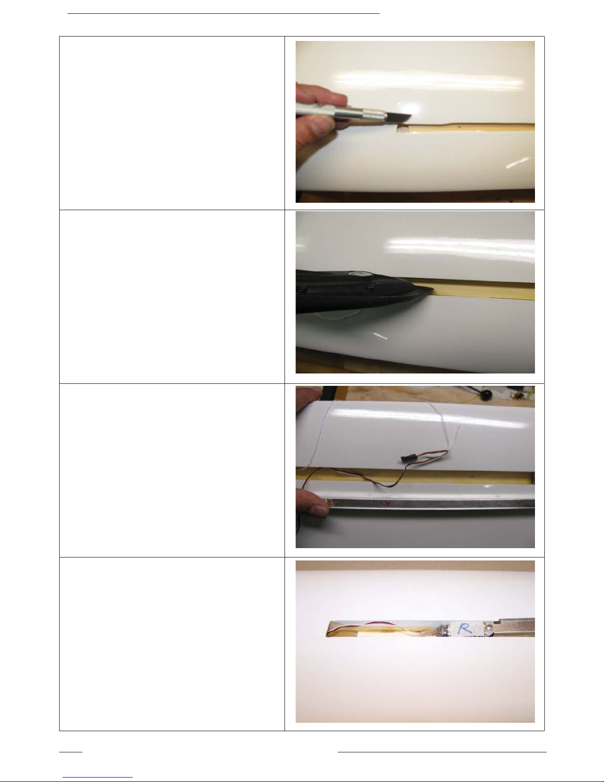
9. If you are fi tting the optional spoilers,
carefully cut the fi lm covering holes for the
spoilers.
10. Using a hobby iron, secure the overlapping
fi lm onto the sides of the hole for the spoilers.
11. Ensure you are installing the left hand spoiler
in the left hand wing and the right hand
spoiler in the right hand wing.
Using the pull cord supplied, attach the cord
to the plug end of the servo lead and pull the
spoiler lead through the wing.
12. Double check you are installing the correct
spoiler in the correct wing.
In the picture opposite, the right hand spoiler
is marked with an R and it is being installed in
the right hand wing.
FITTING OPTIONAL SPOILERS/AIRBRAKES
Page 7
7EScale Fox - Instruction Manual
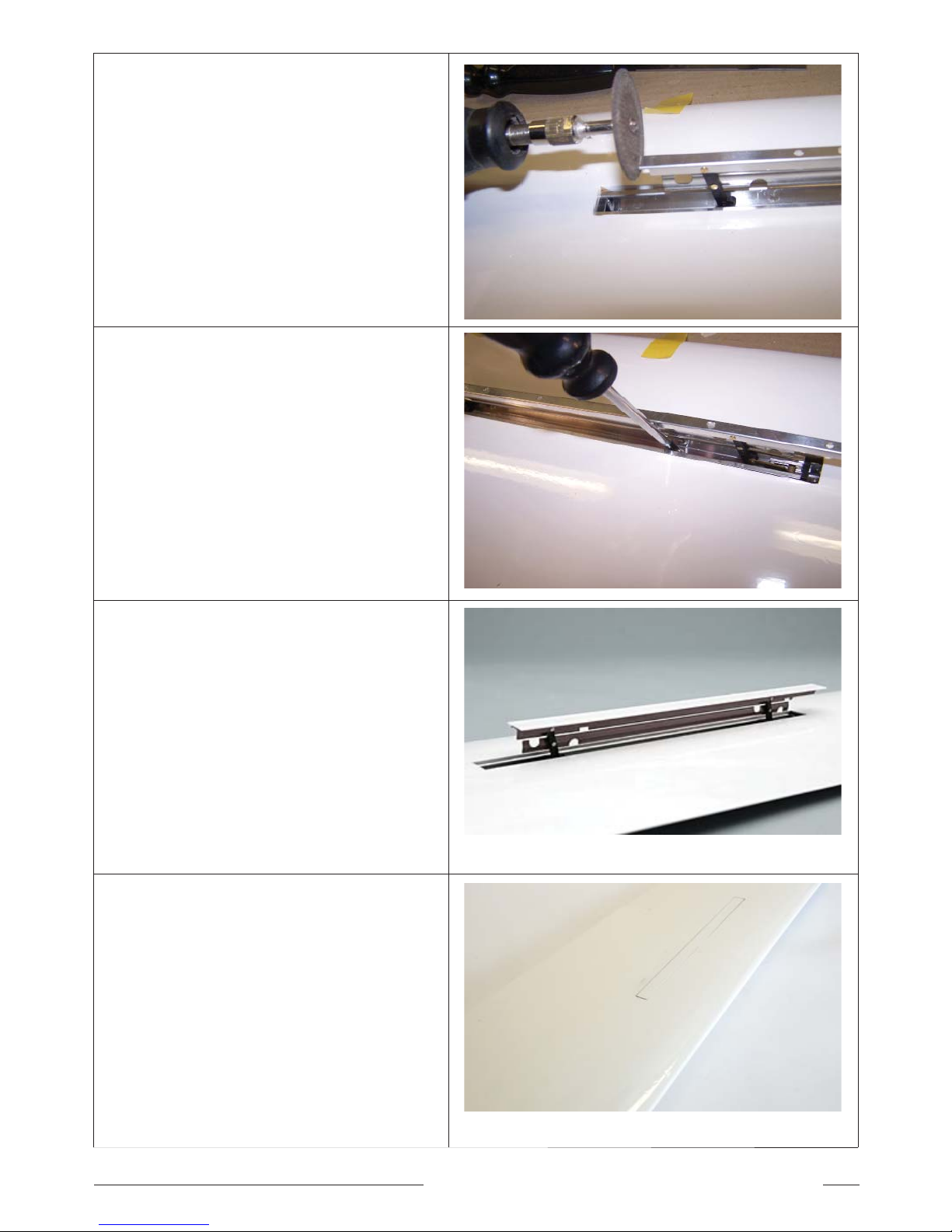
13. Using a servo tester or receiver, check for
smooth operation of the spoilers. You may
have to adjust slightly to ensure the spoiler
operates smoothly.
The picture opposite shows a small section
being removed from the end of the spoiler
blade.
14. The spoiler is retained in the wing by two
small cross head screws.
15. Check the plastic cap strip for fi t then glue in
place using fl exible CA or epoxy.
Rough up the underside of the cap strip with
coarse sandpaper or a fi le to aid adhesion.
Be careful not get glue around the edges of
the cap strip or in the spoiler mechanism.
16. Your completed spoiler should now sit fl at
with the wing surface.
Repeat steps 9-15 for the other wing.
We recommend you run a separate BEC
or receiver battery if you fi t the optional
spoilers as the current drain when
operating the spoilers may exceed the
built in BEC of many electronic speed
controllers.
Page 8
8 EScale Fox - Instruction Manual
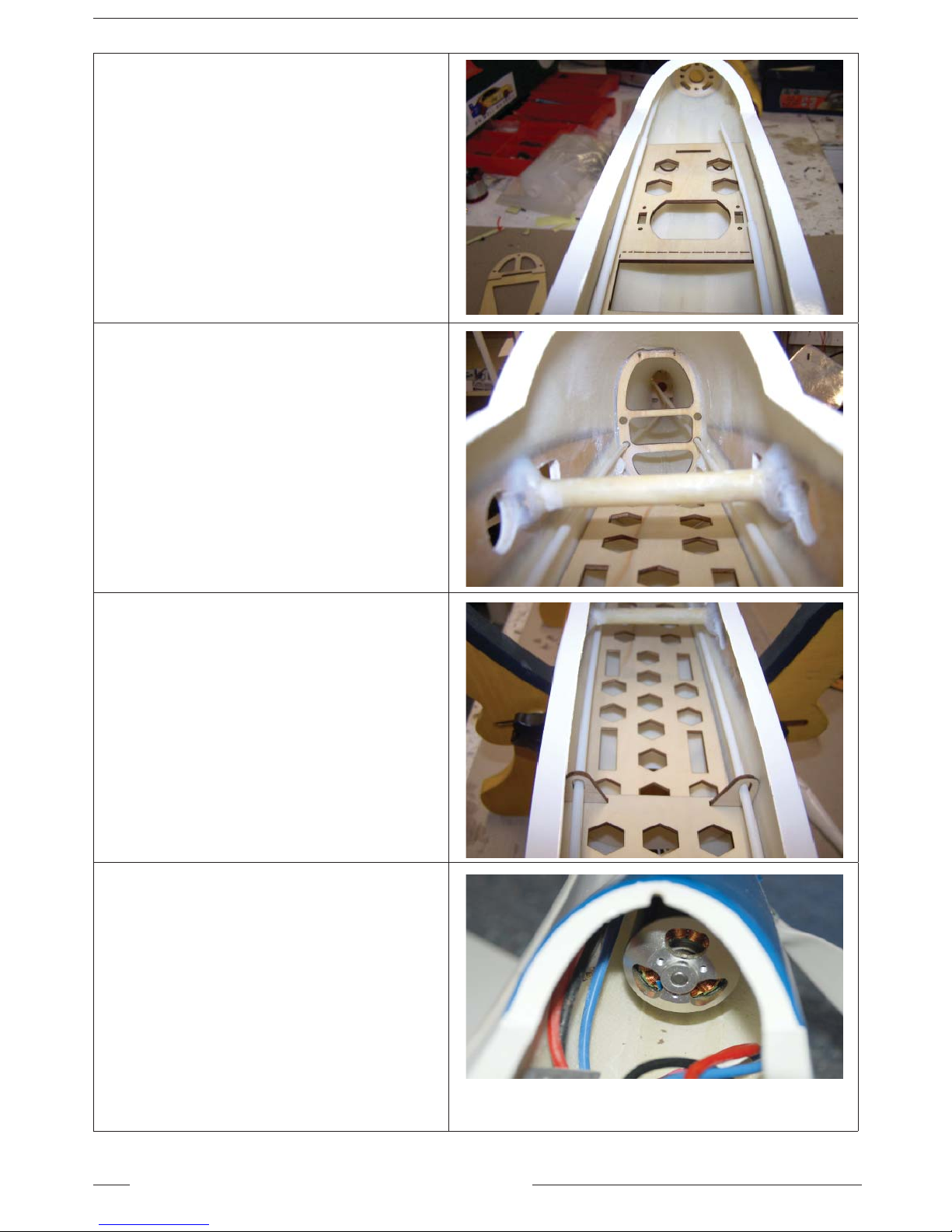
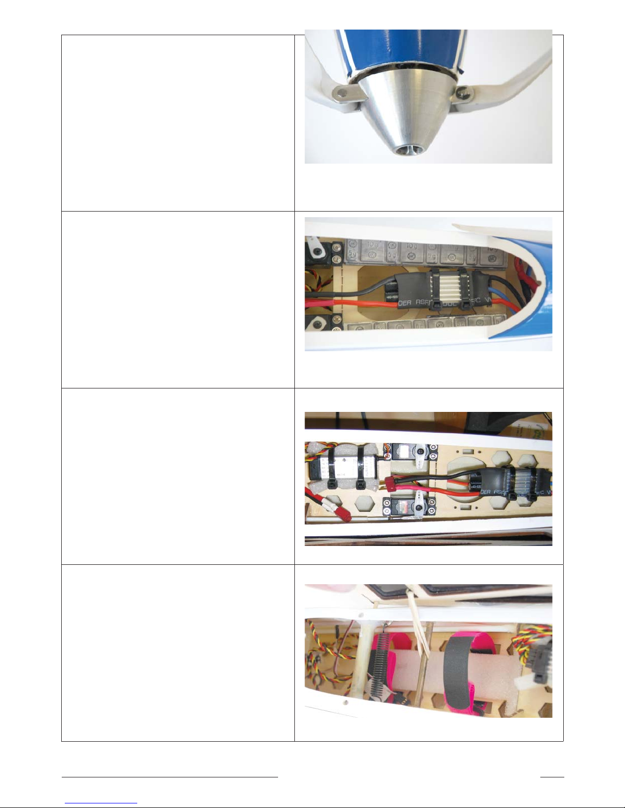
17. Install the plywood formers, trays and
pushrod tubes as shown.
Looking towards the nose.
18. Install the plywood formers, trays and
pushrod tubes as shown.
Looking towards the tail.
19. Install the plywood formers, trays and
pushrod tubes as shown.
Centre section.
20 Fit the motor to the ply plate with bolts
supplied with the motor.
Make sure the motor wires are run well away
from the motor casing.
FITTING SERVOS & OPTIONAL MOTOR, FOLDING PROP & ESC
Page 9
9EScale Fox - Instruction Manual
21. Fit the spinner and folding blades.
22. Attach the motor wires to the ESC and secure
to the front ply tray using cable ties. (ESC
purchased separated).
23. Connect the servos to a servo programmer or
receiver to set for neutral position.
Install the servos for the elevator and rudder.
Connect the pushrods to the servos using the
supplied clevises.
Install the receiver in a receiver wrap and
secure with cable ties.
24. This picture shows the LiPo battery position
in the rear of the cockpit area. Secure the
LiPo battery with Velcro straps or re leasable
cable ties.
Page 10
10 EScale Fox - Instruction Manual
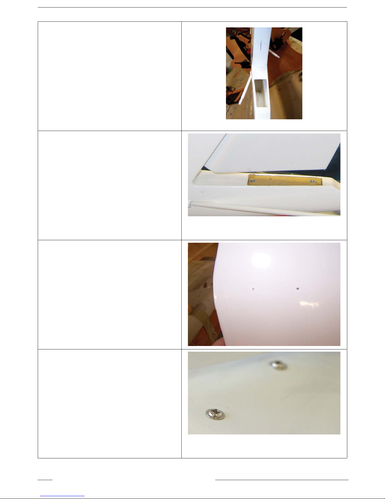
25. This view shows the rear of the fuselage with
the pushrod exits and the slots cut in the
rudder post for the hinges.
26. Install the horizontal stabiliser mount using
30min epoxy.
Install the rudder using the CA hinges
provided. Once positioned use fl exible thin
CA to secure in place.
27 Locate the pre-drilled holes in the horizontal
stabiliser and pierce with a hobby knife.
28. Secure the horizontal stabiliser in place using
the screws provided.
FITTING HORIZONTAL STABILIZER & RUDDER
Page 11
11EScale Fox - Instruction Manual
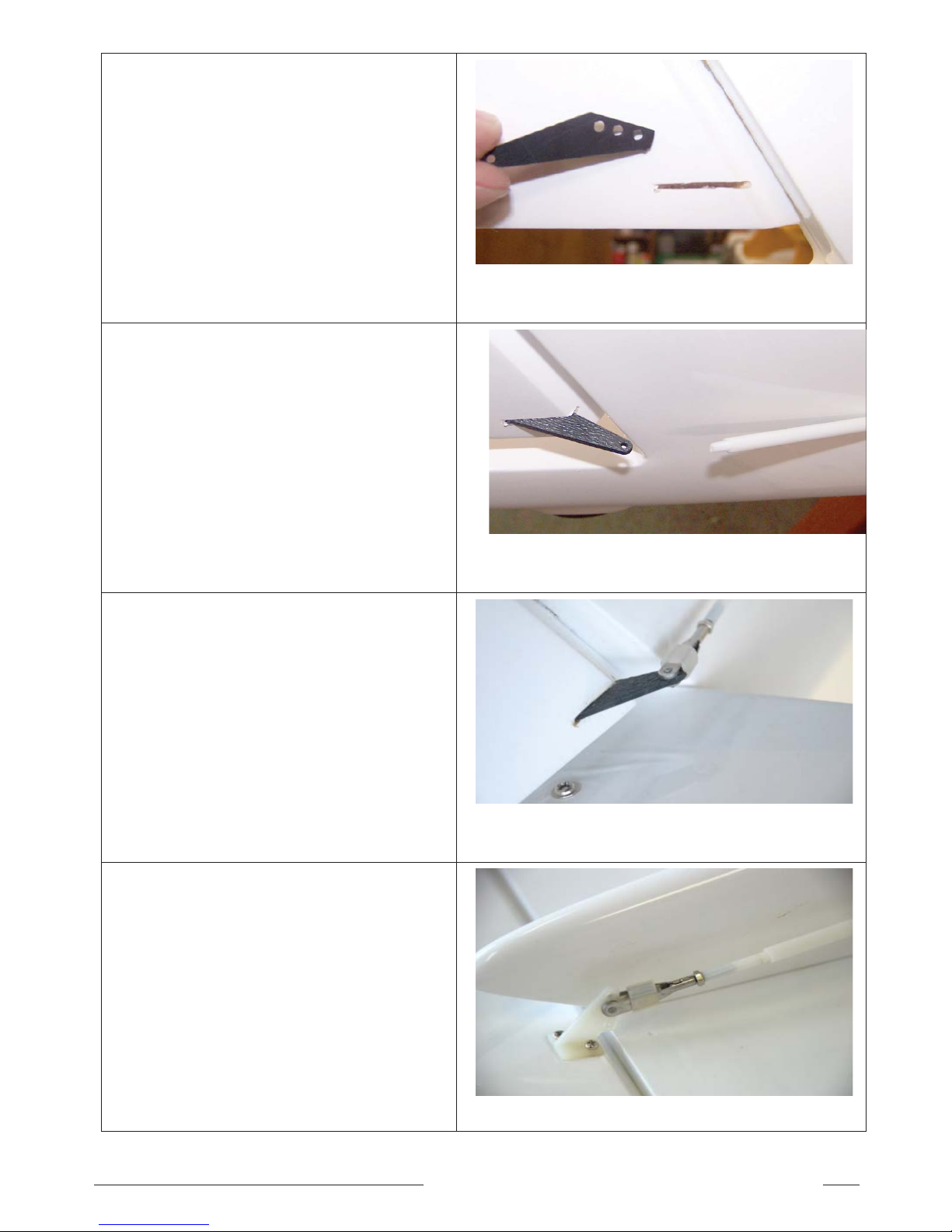
29. Locate the slot in the rudder for the control
horn and remove the fi lm using a sharp hobby
knife.
30. Glue in place using 30 minute epoxy.
31. Connect the pushrod to the control horn using
the supplied clevis.
Remember to add a small piece of silicone
tube to the clevis to prevent it falling off in
fl ight.
32. Install the elevator control horn and connect
the pushrod to the control horn using the
supplied clevis.
Remember to add a small piece of silicone
tube to the clevis to prevent it falling off in
fl ight.
Page 12
12 EScale Fox - Instruction Manual
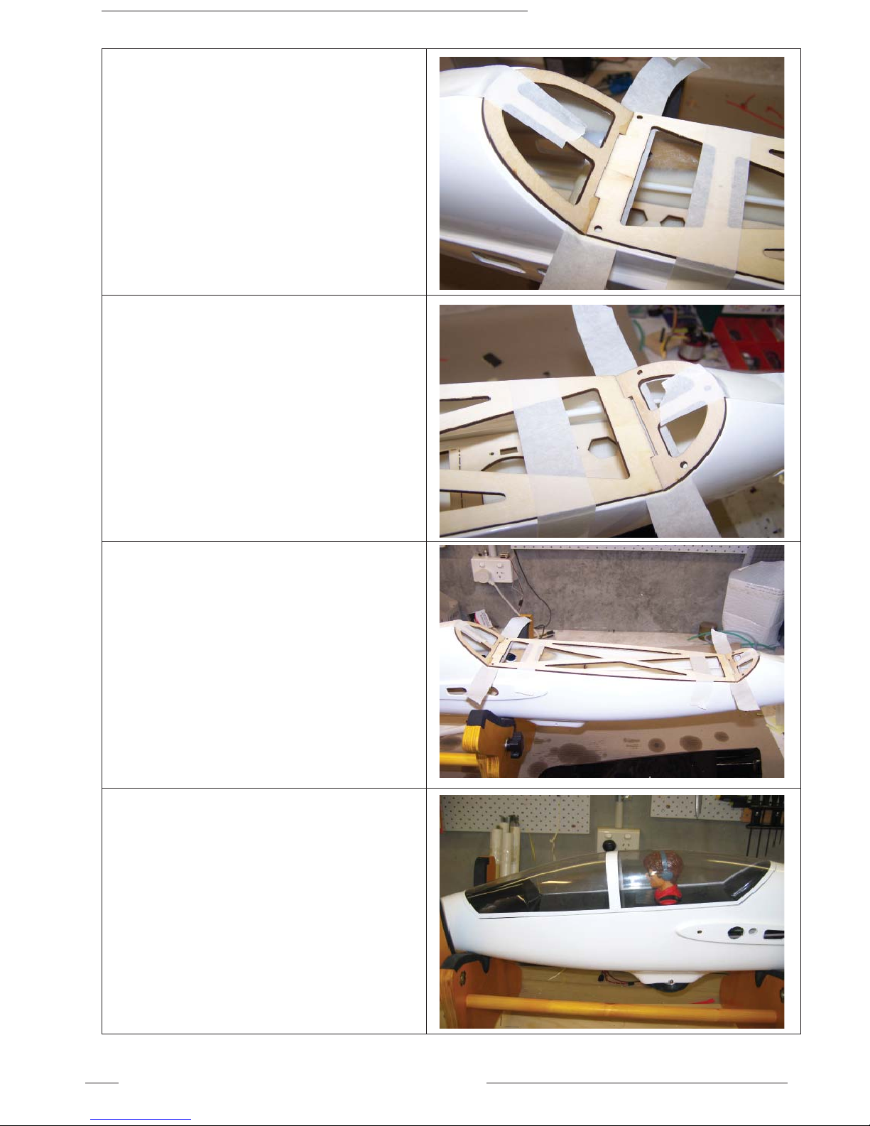
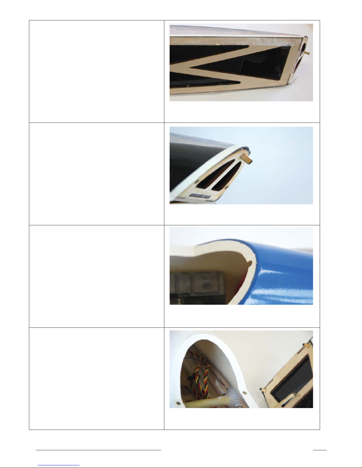
33. Locate the three pieces of plywood that make
up the canopy frame. Trim to fi t using a hobby
knife and sandpaper.
Protect the fuselage and hold the canopy
frame in place with masking tape as shown
Rear of canopy frame shown.
34. Front of canopy frame shown.
35. When you are happy with the fi t, secure the
joins using thick CA,
After the glue has set, carefully remove the
masking tape and CA the other side of the
canopy frame.
36. Carefully trim the clear canopy and cockpit to
fi t the canopy frame. Fit a pilot for increased
scale realism.
FITTING CANOPY FRAME AND CANOPY
Page 13
13EScale Fox - Instruction Manual
37 Secure the canopy frame to the cockpit and
canopy using a suitable canopy glue or tape
using clear tape.
The clear tape method is shown in the picture
and works very well.
38. CA the canopy locating pin in the front of the
canopy frame.
39. Cut a notch for the canopy locating pin using
a rotary tool or fi le in the front of fuselage
canopy opening as shown in the picture.
40. CA the rear locating pins in the base of the
canopy frame.
Drill holes in the fuselage sills to match the
locating pins in the base of the canopy.
Page 14
14 EScale Fox - Instruction Manual
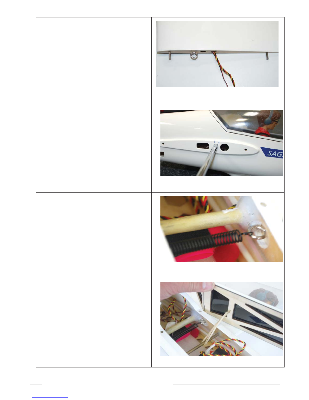
41. Test fi t and epoxy the wing locating pins, two
in each wing.
Screw in the wing retaining eyelet. Use a
small drop of thick CA on the thread of the
eyelet to prevent it coming out.
Repeat for other wing.
42. Install the wing joiner bar and slide the wings
into position, being careful to feed the servo
wires through the holes provided, until the
wings are fl ush with the fuselage.
43 Secure the wings with the supplied retainer
spring.
The spring will attach to the eyelet located on
each wing as shown.
44. Attach the small canopy retaining hook to the
base of the canopy frame and attach to the
fuselage using a rubber band as shown.
FITTING AND SECURING WINGS
Page 15
15EScale Fox - Instruction Manual
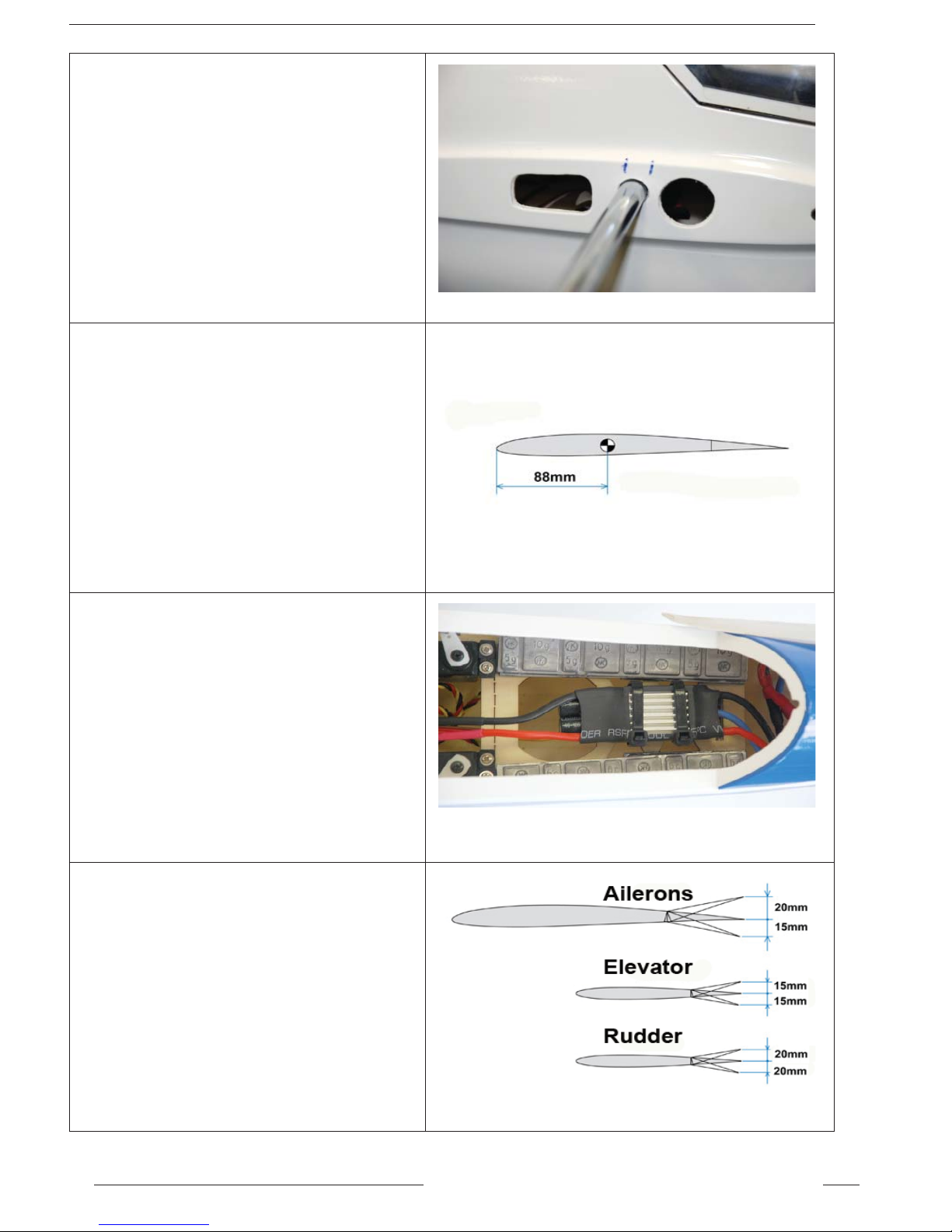
45. Mark your center of gravity (CofG) marks
either side of the fuselage.
Balance the glider upside down with your
fi nger tips on the CofG marks.
Remember to test CofG with your fl ight
battery installed.
46. Test fl ying has shown that 88mm back from
the leading edge at the wing root is a good
safe starting point.
47. You will probably fi nd the FOX will be tail
heavy when you fi rst test the CofG.
Add lead weight to the nose until it balances
evenly.
Our test plane required 240g of lead to be
added as shown.
If the lead you use is not self adhesive,
secure in place with double sided tape or
epoxy.
48. Set up your model in your transmitter and
adjust the control throws to achieve the
fi gures shown. Differential is required on the
ailerons.
Now charge your fl ight pack, stop admiring what
you have done and go fl ying!!!
CHECKING C OF G & CONTROL THROWS
Page 16
June 2010
Australasian agents:
Model Engines, Melbourne, Australia
www.modelengines.com.au
FOX
ARF Aerobatic Electric Glider with
Fibreglass Fuselage & Sheeted Foam Wings
American agents:
Hobby Lobby International, Brentwood, Tennessee, U.S.A.
www.Hobby-Lobby.com
European agents:
J Perkins Distribution, Lenham, England
www.jperkinsdistribution.co.uk
 Loading...