

Escalade sports T8640T User Manual

MODEL NOS.
T8640TT8640T
T8640T
T8640TT8640T
SIERRA
TABLE TENNIS TABLE
OWNER'S MANUAL
1. Read this manual carefully before starting assembly. Read each step completely before beginning each
step.
2. Some smaller parts may be shipped inside larger parts. Check inside all parts and cartons before
assembling or ordering parts.
3. To make assembly easier, use the Hardware Identifier on page 6 to identify and sort all fasteners.
Check all cartons for kits. All hardware may not be located in one kit.
4. Do not tighten hardware until instructed to do so. If hardware is tightened too soon, mounting holes may
not align and parts may not easily fit together. Leave locknuts slightly loose until you are instructed to tighten them.
5. Tools required for assembly: Phillips screwdriver, 7/16” wrenches, and 9/16” wrenches (adjustable wrenches
may be substituted for the wrenches).
Please Do Not Return This Product To The Store!
Contact Escalade® Sports customer service department at:
Phone: 1-866-873-3528 Toll – Free !
Fax: 1-866-873-3533 Toll – Free !
E-mail: tabletennis@escaladesports.com
Mailing Address (correspondence only):
Escalade Sports
PO Box 889
Evansville, IN 47706
Please visit our World Wide Web site at: www.escaladesports.com
ON-LINE TROUBLE SHOOTING TECHNICAL ASSISTANCE
ON-LINE PARTS REQUESTS FREQUENTLY ASKED QUESTIONS
®
ADDITIONAL ESCALADE
SPORTS PRODUCT INFORMATION
Escalade® Sports products may be manufactured and/or licensed under the following patents:
6120397, 5816957, 5769744, 5119741, 4911085, 4717157, D460140, D420563
Additional patents may be pending. One or more of the listed patents and/or pending patents may cover specific product.
2L-4114-00
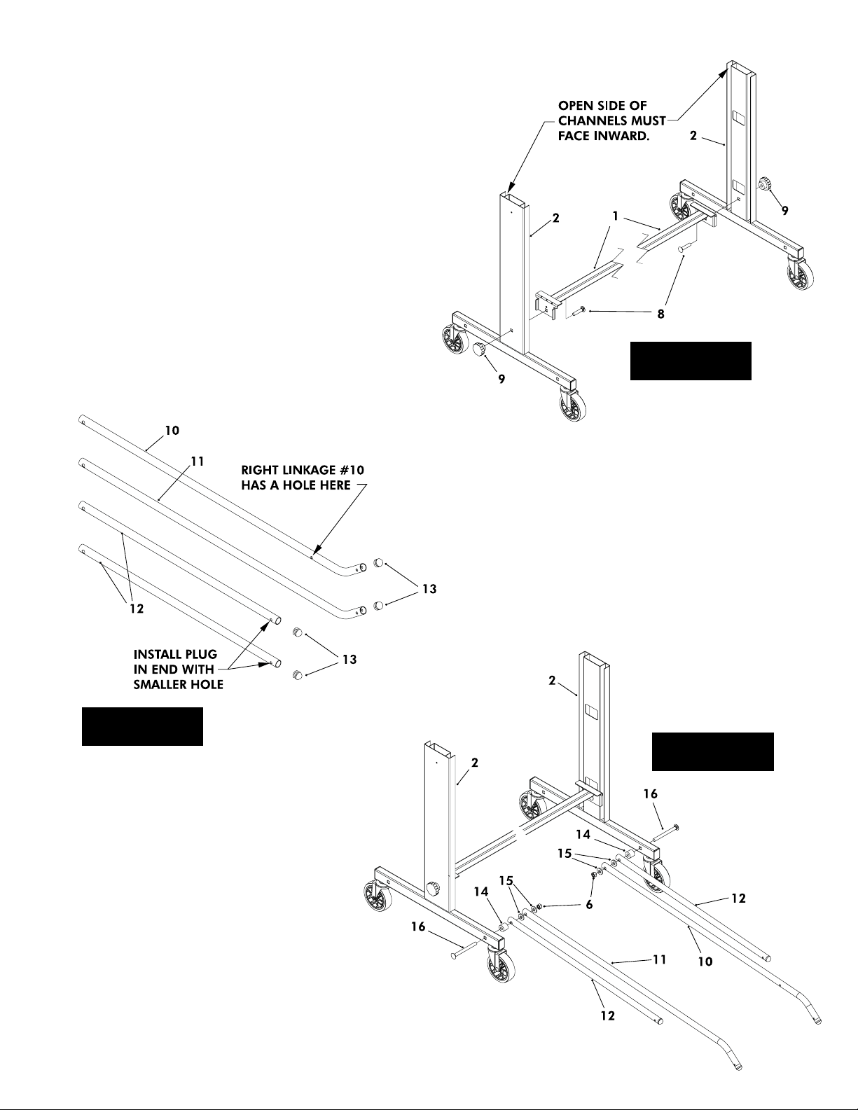
Note: Cross Support (#1) may be packed under both top
assemblies on bottom of carton.
1. Attach Cross Support (#1) to Upright Assemblies (#2), as
shown in Figure 1, using two carriage bolts (#8) and two
Hand Knobs (#9). Note: Assemble "Upright
Assemblies" as shown with channels toward inside.
Tighten Hand Knobs securely.
Figure 1
2. Locate one Right Linkage (#10) (with three holes) and
one Left Linkage (#11) (with two holes) and insert a Round
Top Tube Plug (#13) into bent end. See Figure 2
Figure 2
4. Attach one Strut (#12) and one Right Linkage (#10) to
the righthand Upright Assembly (#2), as shown in Figure
3, using one bolt (#16), one spacer (#14), two spacers
(#15) and one locknut (#6). Tighten bolts tight
but, do not over tighten. Joints must pivot
freely.
5. Attach one Strut (#12) and one Left Linkage (#11)
to the lefthand Upright Assembly (#2), as shown
in Figure 3, using one bolt (#16), one spacer
(#14), two spacers (#15) and one locknut (#6).
Tighten bolts tight but, do not over tighten. Joints
must pivot freely.
3. Locate two Struts (#12) and insert a Round Top Tube
Plug (#13) in the end with smaller hole. See Figure 2
Figure 3
2

6. Insert shoulder Bolt (#17) through Roller Bushing (#18), side
apron and bottom hole in Mounting Bracket (#20) as shown in
Figure 4, and secure with locknut (#19). Tighten bolts tight.
Repeat for other side of table.
Figure 4
7. With the help of another adult pick up one "Top Assembly"
and slide rollers down into slots on "Upright Assembly".
See Figure 5.
DO NOT OPEN THE TABLE TO PLAYING POSITION
UNTIL BOTH TOPS ARE INSTALLED! DO NOT
LEAVE TABLE STANDING UNATTENDED. IT COULD
BE KNOCKED OVER CAUSING SERIOUS BODILY
INJURY OR PROPERTY DAMAGE.
AT LEAST TWO (2) ADULTS ARE NEEDED TO
COMPLETE THE REST OF THIS ASSEMBLY!
Figure 5
Figure 6
8. With one adult holding the "Top Assembly" upright,
swing Struts (#12) up and attach them to mounting
brackets on bottom of "Top Assembly" using one screw
(#21), Spacer (#22) and lock nut (#19) for each
Strut. Tighten bolts tight but, do not over tighten.
Joints must pivot freely. See Figure 6.
3
 Loading...