

Escalade sports T8500 User Manual
OWNER’S MANUAL
Table Tennis Table
Be sure to write your model number and serial number here
for future reference. You can find these numbers printed on
the bottom of the table.
Patent Pending
MODEL # T8500
SERIAL #
READ ASSEMBLY, OPERATING AND SAFETY INSTRUC-
CAUTION:
TIONS CAREFULLY! AT LEAST TWO ADULTS ARE NEEDED
TO PUT THIS TABLE TOGETHER!
Thank you for buying our product. We try hard to ensure that our products are of high quality and free of problems, such as
manufacturing defects or missing parts. However, if you have any problems with your new product, please DO NOT RETURN IT
TO THE STORE!.
DO NOT RETURN THIS PRODUCT TO THE STORE!
Call us at:
TOLL FREE 1-800-426-1421
Please have this Owner’s Manual with you when you call.
Or write us at: CUSTOMER SERVICE DEPT., P.O. Box 889, Evansville, IN 47706
(THIS IS A CONSUMER ONLY NUMBER)
Fax Number: (812) 467-1399.
Or E-mail us at: customerservice@escaladesports.com
Please provide model number and/or part number (not just the key number) of the product and/or part when you call or write. These numbers
can be found on the product, packaging, and/or in this Owner’s Manual.
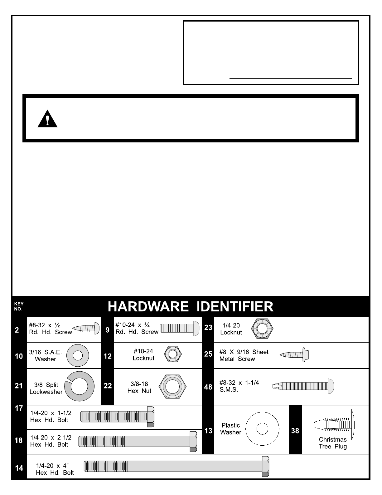
TOOLS NEEDED:
Phillips Screwdriver, Two 7/16 Wrenches, One 3/8 Wrench (an adjustable wrench may be substituted for the
wrenches)
2L-6624-00
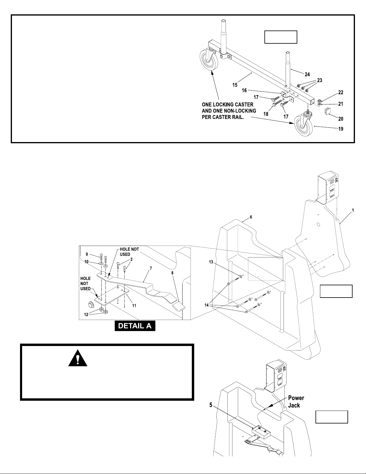
1. Attach two Swaged Tubes #24 to Caster Rail #15, as shown
in Figure 1, using four bolts #17, two bolts #18 and six
nuts #23.
2. Attach a Locking Caster #19 to one end of Caster Rail #15
and a nonlocking Caster to other end using one lockwasher
#21 and one nut #22 per caster. See Figure 1.
3. Repeat steps 1 and 2 for other Caster Rail #15.
4. Secure Panel Insert with electronics #1 to Side Panel #6 using four hex bolts #14 and two Plastic
Washers #13. Note: Panel #1 has four threaded inserts to accept bolts #14. See Figure 2.
5. Slip Safety Latch Cap #8 onto end of Safety Latch #7 and attach Safety Latch to Safety Latch
Mount Plate #11 using two screws #9, two flatwashers #10 and two nuts #12. NOTE: Hole on
left of Safety Latch Mount Plate and hole on right of Safety Latch are not used. See Detail A.
6. Attach Safety Latch Mount Plate #11 to pilot holes in Side Panel #6 using two screws #2.
Figure 1
7. Repeat steps 4 through 6 for Panel Insert without electronics #1.
NOTE: Safety Latches should be installed exactly as shown on
both Side Panels. When Side panels are turned around to face
one another Safety Latches will point opposite directions.
CAUTION:
INSTALL SAFETY LATCHES #7 AS SHOWN ABOVE FOR
PROPER USE OF TABLE! DO NOT SKIP THIS STEP! DO
NOT OPERATE TABLE UNTIL SAFETY LATCHES ARE
INSTALLED AND ASSEMBLY IS COMPLETE!
Figure 2
8. Plug Battery Holder #5 into power jack on Side Panel Assembly with electronics. See Figure 3.
9. Peel backing off of adhesive on bottom of Battery Holder #5
and stick it in the center of the shelf on the Side Panel Assembly with electronics. See Figure 3.
2
Figure 3
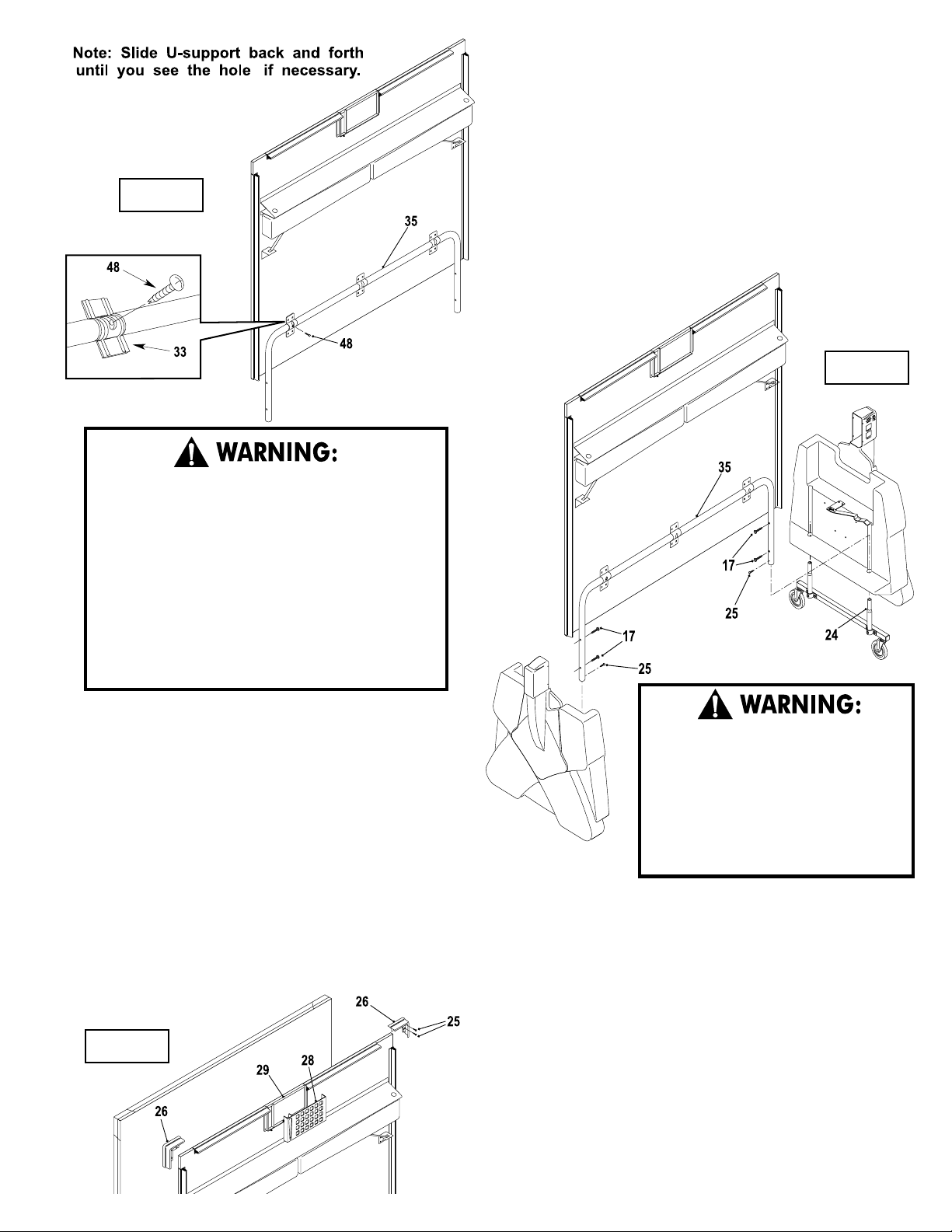
10. Rotate U-support #35 until you see the screw hole in
the slot of U-clip #33. Slide U-support #35 side to side
if necessary. See Figure 4.
Figure 4
AT LEAST FOUR (4) ADULTS ARE NEEDED TO
ASSEMBLE TOPS TO SIDE PANELS! WHEN
ASSEMBLING TOPS TO SIDE PANELS, HANDLE
TOP ASSEMBLIES BY GRASPING ONLY THE TOPS
THEMSELVES. DO NOT GRASP METAL LEGS, USUPPORT, LINKAGE, OR HINGES. THESE PARTS
CAN MOVE AND COULD PINCH FINGERS OR
HANDS CAUSING SERIOUS INJURY! ASSEMBLE
AS SHOWN WITH LEGS FULLY CLOSED AND
TOPS IN A VERTICAL POSITION. DO NOT OPEN
LEGS AND TRY TO ASSEMBLE. TABLE TOPS ARE
HEAVY - DO NOT ATTEMPT TO ASSEMBLE ALONE!
11. Insert screw #48 through slot in U-clip #33 and into
U-support #35. Thread it all the way into U-support
#35 until it touches the back of the tube. There should
be about 3/8 inch of screw #48 left sticking out.
Figure 5
12. Insert Caster Rail Assemblies into Side Panel Assemblies
as shown in Figure 5.
13. With four adults, attach table top (#30) to table base, as
shown in Figure 5. With one adult holding each Side Panel
Assembly upright and at least one adult on each side of
table top, lift top and align ends of "U"-support tube #35
with top of Swaged Tubes #24. Slide tubes together.
IMPORTANT! Make sure U-support tubes slide all the
way on Swaged Tubes.
14. With four adults, put other table top onto other pivot tubes
following instructions for first table top.
15. Secure top assemblies to Side Panel Assemblies using four
bolts #17 for each top assembly. See Figure 5. Note: Side
Panel Assemblies have threaded inserts to accept bolts
#17.
Figure 6
DO NOT OPEN THE TABLE TO
PLAYING POSITION UNTIL BOTH
TOPS ARE INSTALLED! DO NOT
LEAVE TABLE STANDING
UNATTENDED. IT COULD BE
KNOCKED OVER CAUSING SERIOUS
BODILY INJURY OR PROPERTY
DAMAGE.
16. Thread two screws #25 into bottom holes in each "U"support tube #35. See Figure 5.
17. Attach four Corner Caps #26 to table tops using three
screws #25 for each Corner Cap. See Figure 6.
18. Snap both Storage Tray Bottoms #28 to Storage Tray Tops.
No fasteners are necessary. See Figure 6.
3
 Loading...