

Escalade sports T8266 User Manual
OWNER’S MANUAL
Table Tennis Table
Be sure to write your model number and serial number here
for future reference. You can find these numbers printed on
the bottom of the table.
Patent Pending
MODEL # T8266
SERIAL #
READ ASSEMBLY, OPERATING AND SAFETY INSTRUC-
CAUTION:
TIONS CAREFULLY! AT LEAST TWO ADULTS ARE NEEDED
TO PUT THIS TABLE TOGETHER!
Thank you for buying our product. We try hard to ensure that our products are of high quality and free of problems, such as
manufacturing defects or missing parts. However, if you have any problems with your new product, please DO NOT RETURN IT
TO THE STORE!.
DO NOT RETURN THIS PRODUCT TO THE STORE!
Call us at:
TOLL FREE 1-800-426-1421
Please have this Owner’s Manual with you when you call.
Or write us at: CUSTOMER SERVICE DEPT., P.O. Box 889, Evansville, IN 47706
(THIS IS A CONSUMER ONLY NUMBER)
Fax Number: (812) 467-1399.
Or E-mail us at: customerservice@escaladesports.com
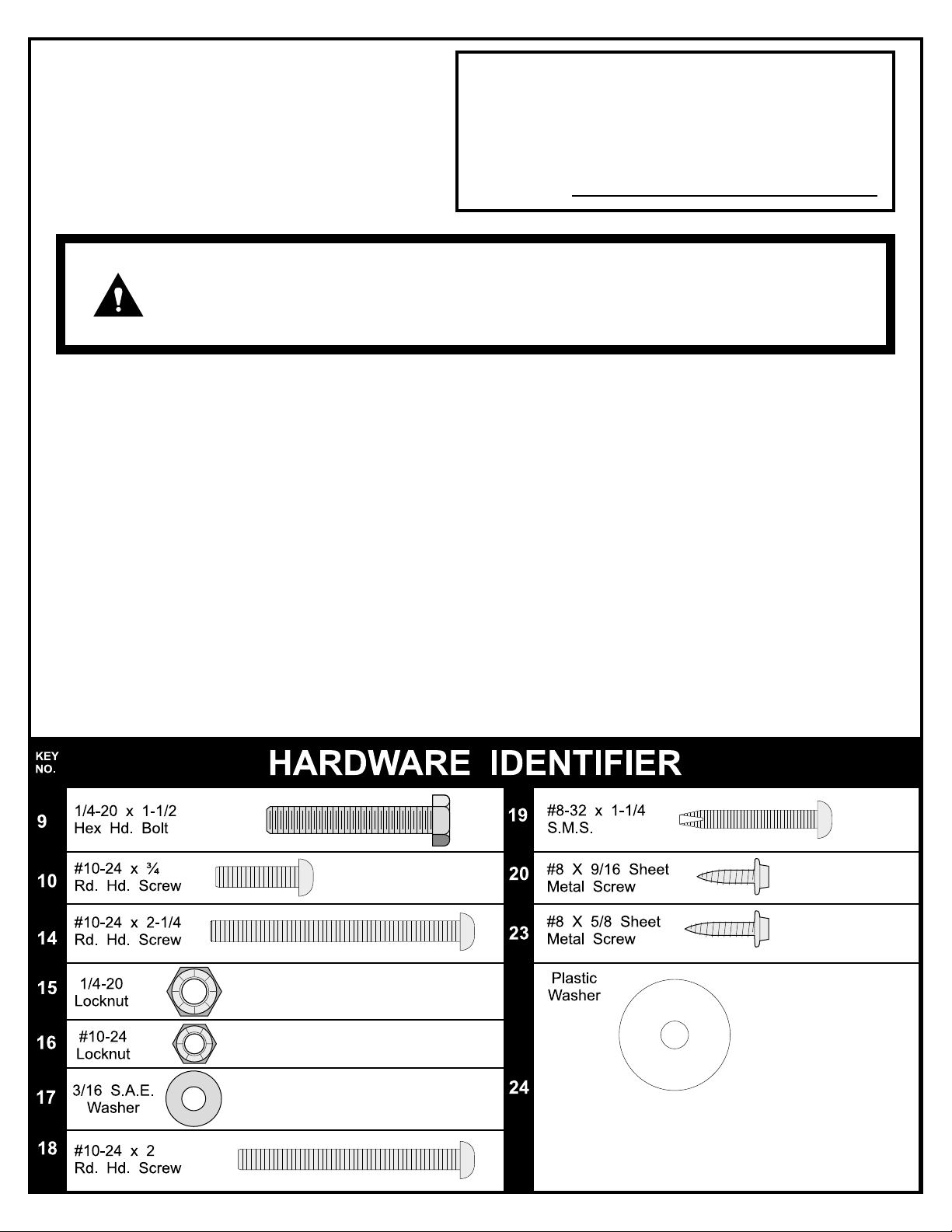
Please provide model number and/or part number (not just the key number) of the product and/or part when you call or write. These numbers
can be found on the product, packaging, and/or in this Owner’s Manual.
TOOLS NEEDED:
Phillips Screwdriver, Two 7/16 Wrenches, One 3/8 Wrench (an adjustable wrench may be substituted for the
wrenches), Tape Measure
2L-6599-02
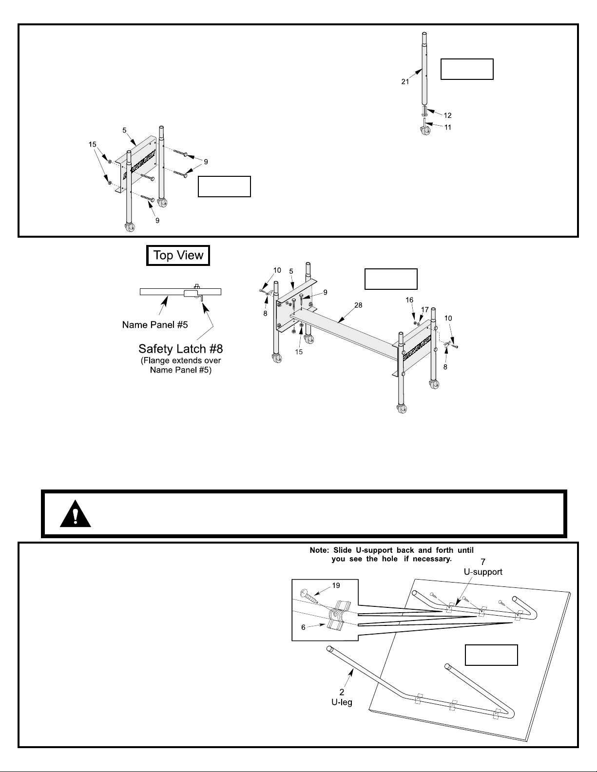
1. Gently tap a caster socket #12 into each Upright Tube
#21 until flange on sockets touches the edge of the tube.
DO NOT HIT CASTER SOCKET TOO HARD WITH A HAMMER! Sockets may break if hit too hard.
2. Insert casters #11 into caster sockets #12.
3. Attach two Upright Tube Assemblies to both Name Plates
Figure 2
Figure 1
#5, as shown in Figure 2, using four bolts #9 and four
nuts #15.
Figure 3
4. Connect the two Name Plate Assemblies to the Bottom Board #28, as shown in Figure 3, using four bolts #9 and four
nuts #15.
5. Install a safety latch #8 into the right-hand hole on each name panel as shown in Figure 3. Use one screw #10 one
washer #17 and one hex nut #16. NOTE: Flange on safety latch must extend over top of name panel as shown in
Figure 3. Safety latch must pivot freely.
INSTALL SAFETY LATCHES #8 AS SHOWN ABOVE FOR PROPER USE
CAUTION:
6. Rotate U-support #7 until you see the screw hole in
the slot of U-clip # 6. Slide U-support #7 side to side if
necessary. See Figure 4.
7. Insert screw #19 through slot in U-clip #6 and into Usupport #7. Thread it all the way into U-support #7
until it touches the back of the tube. There should be
about 3/8 inch of screw #19 left sticking out.
OF TABLE! DO NOT SKIP THIS STEP! DO NOT OPERATE TABLE UNTIL
SAFETY LATCHES ARE INSTALLED AND ASSEMBLY IS COMPLETE!
Figure 4
2
 Loading...