

Escalade sports T8254 User Manual
OWNER'S MANUAL
MODEL NO.
T8254
Thank you for buying our product. We try hard to ensure that our products are of high
quality and free of problems, such as manufacturing defects or missing parts. However,
if you have any problems with your new product, please DO NOT RETURN IT TO THE
STORE!.
DO NOT RETURN THIS PRODUCT TO THE STORE!
Call us at:
TOLL FREE 1-800-426-1421
(THIS IS A CONSUMER ONLY NUMBER)
Please have this Owner’s Manual with you when you call.
READ ASSEMBLY AND OPERATING
INSTRUCTIONS, AND SAFETY
INFORMATION CAREFULLY
!
Or write us at: CUSTOMER SERVICE DEPT., P.O. Box 889, Evansville, IN 47706
Please provide model number and/or part number (not just the key number) of the product and/
or part when you call or write. These numbers can be found on the product, packaging, and/or in
this Owner’s Manual.
Fax Number: (812) 467-1399.
AT LEAST TWO PEOPLE ARE
WARNING
NEEDED TO PUT THIS TABLE
TOGETHER!
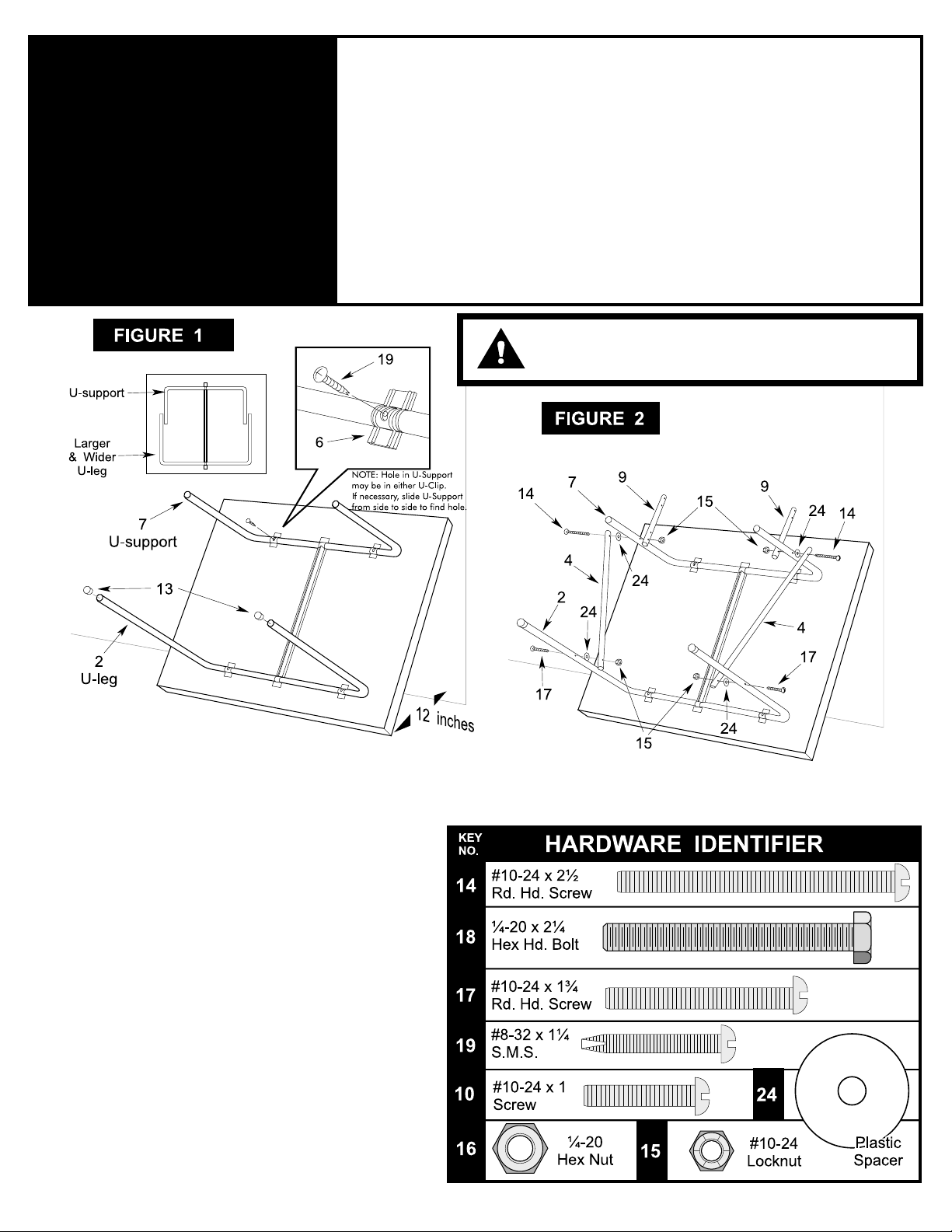
1. Lean either table half #1 against a wall with the larger
and wider U-leg #2 near the floor. (See Figure 1). Place
bottom of table about 12" from wall.
IMPORTANT NOTE: If floor is not carpeted, be sure to
place a heavy object at the base of the table half to
help prevent table half from sliding away from wall.
2. Rotate wider U-leg #2 out from table and put caps #13
on its ends. (See Figure 1)
3. Rotate U-support #7 until you see the screw hole in the
slot of U-clip #6 (See Figure 1, Detail). Slide U-support
#7 side to side if necessary. NOTE: Screw hole may be
in either U-clip. If you don't see hole in slot of one Uclip, look for it in the other U-clip.
4. Insert screw #19 through slot in U-clip #6 and into U-
support #7. Thread it all the way into U-support #7 until
it touches the back of the tube. There should be about
3/8 inch of screw #19 left sticking out. (See Figure 1)
5. Attach linkages #4 to INSIDE of U-leg #2. Secure with
screws #17, spacers #24, locknuts #15 and thread
protectors #23. (See Fig 2) Tighten hardware snug to
keep table stable but do not overtighten. Tubes must
pivot.
6. Attach free end of linkages #4 to OUTSIDE of U-support
#7 with screws #14 and spacers #24. Then slide
braces #9 onto the same screws #14 on INSIDE of Usupport #7. Secure with locknuts #15. (See Figure 2)
Tighten snug but do not overtighten. Tubes must
pivot.
You will need the following tools to put your table together:
! Phillips and Standard (Flat Blade) Screwdrivers
! 7/16 and 3/8 Wrenches (Adjustable wrench may be used instead.)
2L-6568-00
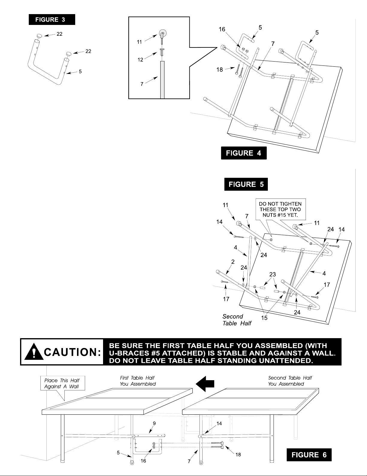
7. Put tube plugs #22 into both U-braces #5. (See Figure 3).
8. Gently tap caster sockets #12 into U-support #7 until flange on
sockets touches the edge of tube. DO NOT USE FORCE OR A
HAMMER! (See Figure 4). Insert casters #11 into caster sockets
#12.
9. Attach U-brace #5 to U-supports #7. (See Figure 4) Secure with hex
bolts #18 and locknuts #16. Tighten nuts but be careful not to crush
tubes.
10. Repeat steps 1 - 5 on second table half. REMEMBER, if floor is not
carpeted, be sure to brace table half with a heavy object to help
keep it from sliding.
11. Gently tap caster sockets #12 into U-support #7 until flange on
sockets touches the edge of tube. DO NOT USE FORCE OR A
HAMMER! (See Figures 4 & 5). Insert casters #11 into caster
sockets #12.
12. With second table half against wall, attach linkages #4 to OUTSIDE
of U-support #7. Use screws #14. (See Figure 5) NOTE: Tighten
locknuts #15 only finger tight. They will be removed when two table
halves are connected.
13. Make sure legs on the table half with the U-braces #5 (the first half
you assembled) are open. With one person on each side of table, lift
and set table half on its legs. Place table against a wall as shown below
to help stabilize table half while second half is being attached. Be sure
there is enough room to connect second half.
14. SEE CAUTION BELOW!
15. Place two hex bolts #18 and locknuts #16 on floor next to caster
wheels (both sides of table half) so they will be handy for the next step.
16. With a person on both sides of second table half (the half without U-
braces #5), slide second table half against first table half. Align
holes in U-braces #5 with holes in U-support #7. Secure with hex bolts
#18 and locknuts #16. Do not tighten nuts until after step #17. (See
Figure 6)
2
 Loading...