

Escalade sports T8176 User Manual

MODEL NO.
T8176T8176
T8176
T8176T8176
QUICK SERVE 3000
TABLE TENNIS TABLE
OWNER'S MANUAL
1. Read this manual carefully before starting assembly. Read each step completely before beginning
each step.
2. Some smaller parts may be shipped inside larger parts. Check inside all parts and cartons
before assembling or ordering parts.
3. To make assembly easier, use the Hardware Identifier on page 7 to identify and sort all
fasteners. Check all cartons for kits. All hardware may not be located in one kit.
4. Do not tighten hardware until instructed to do so. If hardware is tightened too soon, mounting holes
may not align and parts may not easily fit together. Leave locknuts slightly loose until you are instructed to
tighten them.
5. Tools required for assembly: Phillips Screwdriver, Two 7/16 Wrenches, One 3/8 Wrench (an adjustable
wrench may be substituted for the wrenches), Flat Blade Screw Driver
Please Do Not Return This Product To The Store!
Contact Escalade® Sports customer service department at:
Phone: 1-866-873-3528 Toll – Free !
Fax: 1-866-873-3533 Toll – Free !
E-mail: tabletennis@escaladesports.com
Mailing Address (correspondence only):
Escalade Sports
PO Box 889
Evansville, IN 47706
Please visit our World Wide Web site at: www.escaladesports.com
ON-LINE TROUBLE SHOOTING TECHNICAL ASSISTANCE
ON-LINE PARTS REQUESTS FREQUENTLY ASKED QUESTIONS
ADDITIONAL ESCALADE® SPORTS PRODUCT INFORMATION
Escalade® Sports products may be manufactured and/or licensed under the following patents.
6120397, 5816957, 5769744, 5119741, 4911085, 4717157, D460140, D420563
Additional patents may be pending. One or more of the listed patents and/or pending patents may cover specific product.
2L-6872-01
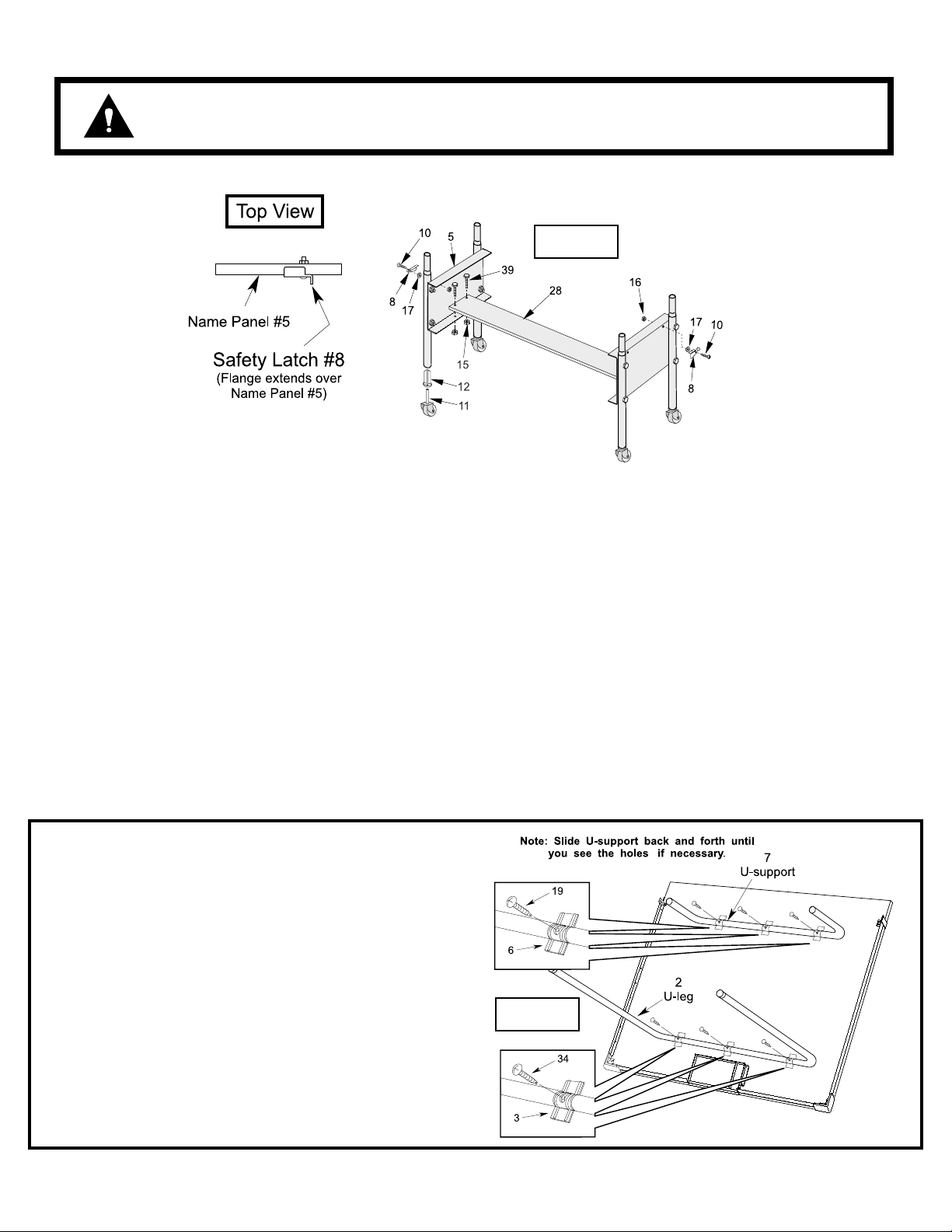
INSTALL SAFETY LATCHES #8 AS SHOWN BELOW FOR PROPER USE OF
CAUTION:
TABLE! DO NOT SKIP THIS STEP! DO NOT OPERATE TABLE UNTIL SAFETY
LATCHES ARE INSTALLED AND ASSEMBLY IS COMPLETE!
Figure 1
1. Gently tap four caster sockets #12 into Name Panel Assemblies until flange on sockets touches the edge of the tube. DO NOT HIT
CASTER SOCKET DIRECTLY! Place a block of wood on Caster Sockets and tap on wood with hammer. See Figure 1.
2. Insert casters #11 into caster sockets #12.
3. Connect the two Name Plate Assemblies to the Bottom Board #28, as shown in Figure 1, using four bolts #39 and four nuts #15.
4. Install a safety latch #8 into the right-hand hole on each name panel as shown in Figure 1. Use one screw #10 one washer #17 and one
hex nut #16. NOTE: Flange on safety latch must extend over top of name panel as shown in Figure 1. Safety latch must
pivot freely.
5. Rotate U-support #7 until you see the screw holes in the slots
of U-clips # 6. Slide U-support #7 side to side if necessary. See
Figure 2.
6. Insert a screw #19 through slot in each U-clip #6 and into Usupport #7. Thread each screw all the way into U-support #7
until it touches the back of the tube. There should be about 3/
8 inch of screw #19 left sticking out.
7. Rotate U-leg #2 until you see the screw holes in the slots of Uclips #3. Slide U-leg #2 side to side if necessary. See Figure 2.
Figure 2
8. Insert a screw #34 through slot in each U-clip #3 and into Uleg #2. Thread each screw all the way into U-leg #2 until it
touches the back of the tube. There should be about 3/8 inch
of screw #19 left sticking out.
2
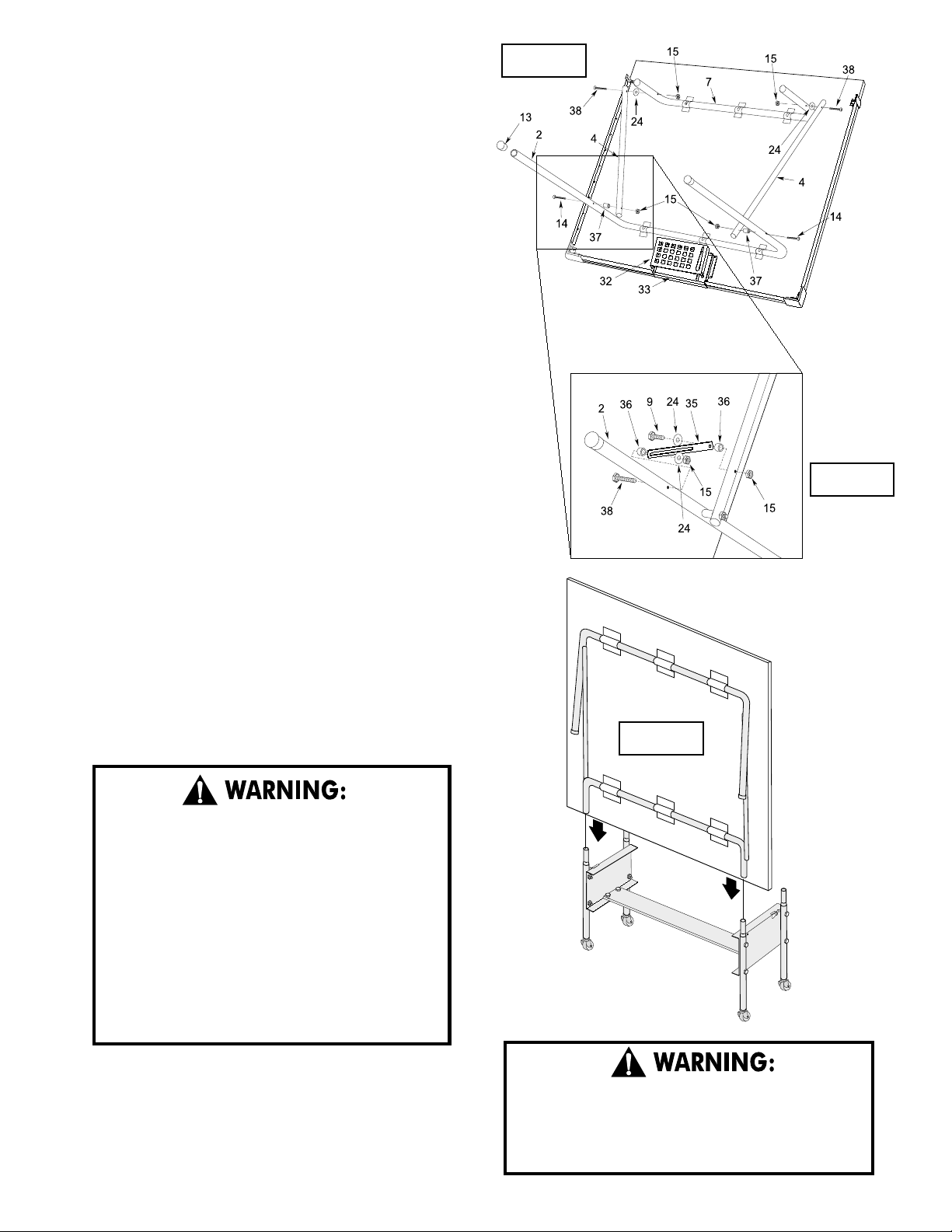
9. Lay table top #1 painted side down, on a smooth, flat surface. Use
the shipping container to protect the painted surface of the table
top.
10. Attach end of linkages #4 with two holes to INSIDE of U-leg #2 as
shown in Figure 3. Secure with bolts #14, locknuts #15 and plastic spacers #37. Tighten hardware snug enough to keep table stable
but do not overtighten. Tubes must pivot freely. NOTE: Plastic spacers go between linkages #4 and U-leg #2.
11. Attach other end of linkages #4 to OUTSIDE of U-support #7
with bolts #38, locknuts #15 and plastic washers #24. Tighten
hardware until snug but do not overtighten. Tubes must pivot freely.
12. Install leg cap #13 onto end of U-legs #2.
13. Snap Lower Paddle Box #32 to Upper Paddle Box #33.
14. On one side of the table attach slotted end of safety strap #35 to
INSIDE of U-Leg #2 using one bolt #38, one spacer #36, one
washer #24, and one locknut #15. Tighten hardware until snug
but do not overtighten. Tubes must pivot freely. See Figure 4.
Figure 3
15. Attach other end of safety strap #35 to OUTSIDE of linkage #4
using one bolt #9, one washer #24, one spacer #36, and one
locknut #15.
16. Prepare an area for the assembly of the second table top half. If
necessary, move the first table top half aside with the aid of a helper.
Be sure to place it in a location where it won't be disturbed or damaged. If setting on its side, be sure to place the bottom edge no less
than 12 inches away from the wall. Also be sure to place carpet or
pieces of the shipping carton down to protect table top edges. If
floor is not carpeted, brace table top half with a heavy object to
keep it from sliding.
17. Repeat steps 5 thru 15 on second table half.
AT LEAST TWO (2) ADULTS ARE NEEDED TO
COMPLETE THE REST OF THIS ASSEMBLY! WHEN
ASSEMBLING TOPS TO BASE, HANDLE TOP
ASSEMBLIES BY GRASPING ONLY THE TOPS
THEMSELVES. DO NOT GRASP METAL LEGS, USUPPORT, LINKAGE, OR HINGES. THESE PARTS
CAN MOVE AND COULD PINCH FINGERS OR
HANDS CAUSING SERIOUS INJURY! ASSEMBLE
AS SHOWN WITH LEGS FULLY CLOSED AND
TOPS IN A VERTICAL POSITION. DO NOT OPEN
LEGS AND TRY TO ASSEMBLE. TABLE TOPS ARE
HEAVY - DO NOT ATTEMPT TO ASSEMBLE
ALONE!
Figure 4
Figure 5
18. With two adults, attach table top (#1) to table base, as shown in
Figure 5. With at least one adult on each side of table top, lift top
and align ends of "U"-support tube with top of upright tubes. Slide
tubes together.
19. With two adults, put other table top onto other pivot tubes following
instructions in previous step.
DO NOT OPEN THE TABLE TO PLAYING POSITION
UNTIL BOTH TOPS ARE INSTALLED! DO NOT LEAVE
TABLE STANDING UNATTENDED. IT COULD BE
KNOCKED OVER CAUSING SERIOUS BODILY INJURY
OR PROPERTY DAMAGE.
3
 Loading...