

Escalade sports T8129 User Manual

MODEL NO.
T8129T8129
T8129
T8129T8129
CHALLENGER
TABLE TENNIS TABLE
OWNER'S MANUAL
1. Read this manual carefully before starting assembly. Read each step completely before beginning
each step.
2. Some smaller parts may be shipped inside larger parts. Check inside all parts and cartons
before assembling or ordering parts.
3. To make assembly easier, use the Hardware Identifier on page 7 to identify and sort all
fasteners. Check all cartons for kits. All hardware may not be located in one kit.
4. Do not tighten hardware until instructed to do so. If hardware is tightened too soon, mounting holes
may not align and parts may not easily fit together. Leave locknuts slightly loose until you are instructed to
tighten them.
5. Tools required for assembly: Phillips Screwdriver, 3/8 Wrench, and Two 7/16 Wrenches (adjustable
wrenches may be substituted for the wrenches).
Please Do Not Return This Product To The Store!
Contact Escalade® Sports customer service department at:
Phone: 1-866-873-3528 Toll – Free !
Fax: 1-866-873-3533 Toll – Free !
E-mail: tabletennis@escaladesports.com
Mailing Address (correspondence only):
Escalade Sports
PO Box 889
Evansville, IN 47706
Please visit our World Wide Web site at: www.escaladesports.com
ON-LINE TROUBLE SHOOTING TECHNICAL ASSISTANCE
ON-LINE PARTS REQUESTS FREQUENTLY ASKED QUESTIONS
®
ADDITIONAL ESCALADE
SPORTS PRODUCT INFORMATION
2L-7028-02
Escalade® Sports products may be manufactured and/or licensed under the following patents.
6120397, 5816957, 5769744, 5119741, 4911085, 4717157, D460140, D420563
Additional patents may be pending. One or more of the listed patents and/or pending patents may cover specific product.
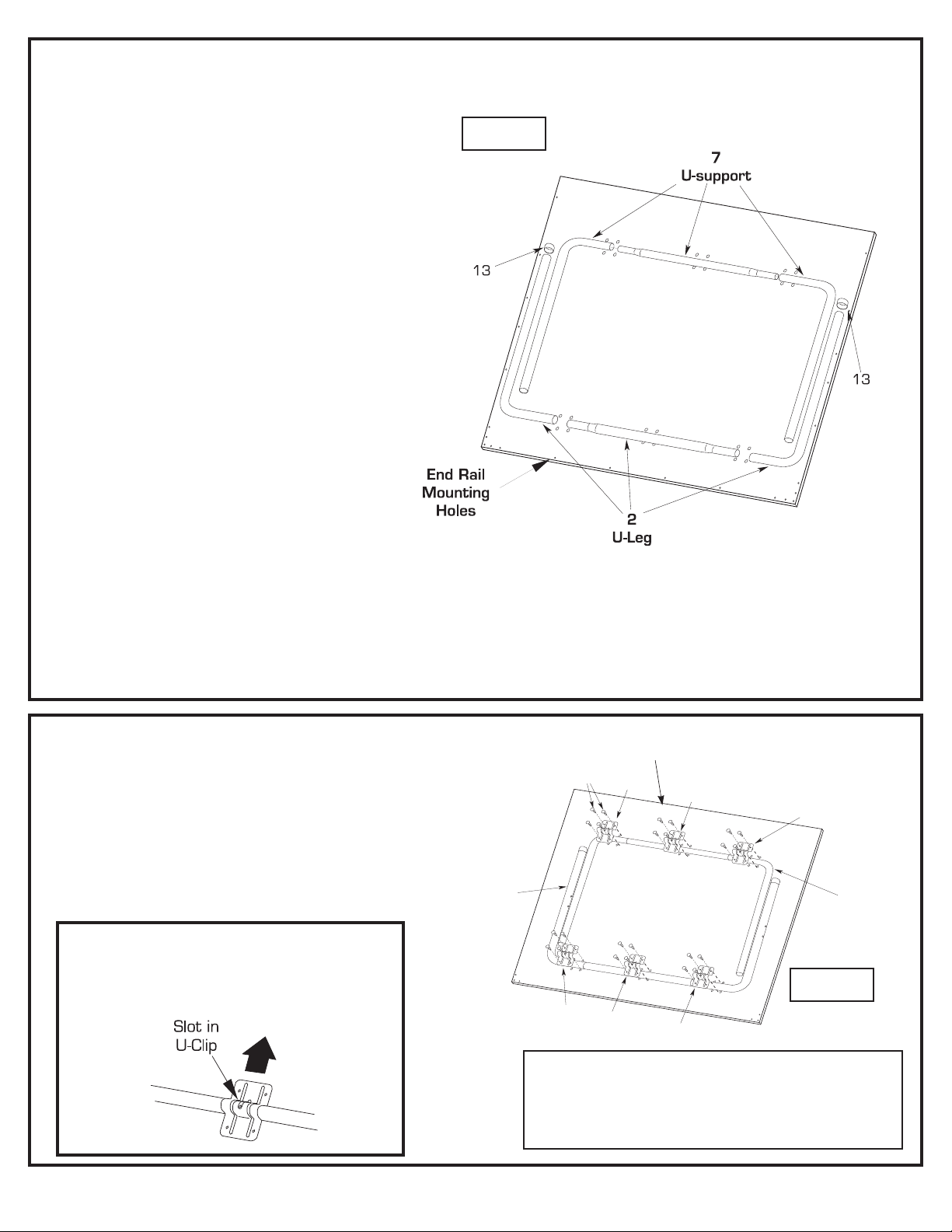
For aid in identifying hardware, see hardware identifier on page 7.
2
U-Leg
7
U-support
Allscrewsshown
are(#20)sheet
metalscrews.
18
20
18
18
3
3
3
Thisendisthe
middleofthetable
Figure 1
1. Lay table top #1 painted side down, on a smooth, flat
surface. Use the shipping container to protect the
painted surface of the table top.
2. Assemble the two “L” tubes and the center tubes that
make up the “U” Support and the “U” Leg. Align on
Table Top as shown in Figure 1. Note: “U” Leg is
larger and wider than the U Support. The Uleg should be installed on the end of the table
half with the end rail mounting holes.
3. Put plastic caps #13 on the end of U-leg #2.
4. Align the holes in the Large U-clips #3 and the U-clips #18
with pilot holes in table top assembly and secure with twenty
four screws #20 as shown.
Be sure the slot in the six U-clips #3 all face theBe sure the slot in the six U-clips #3 all face the
Be sure the slot in the six U-clips #3 all face the
Be sure the slot in the six U-clips #3 all face theBe sure the slot in the six U-clips #3 all face the
same direction (toward the middle of the tablesame direction (toward the middle of the table
same direction (toward the middle of the table
same direction (toward the middle of the tablesame direction (toward the middle of the table
with the U-support) as shown.with the U-support) as shown.
with the U-support) as shown.
with the U-support) as shown.with the U-support) as shown.
IMPORTANT:
Figure 2
IMPORTANT: U-Leg is wider than U-support.
Make sure they are assembled exactly as
shown. If not, there will be a large gap between
table halves and table will not operate properly!
2
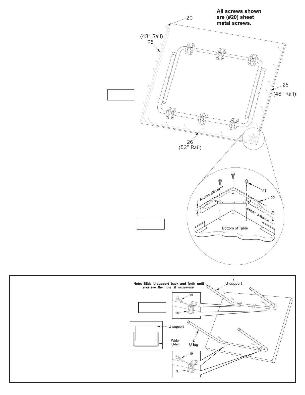
5. Lay out rails #25 and 26, as shown in Figure 3, around edges
of table top.
6. Line up holes in rails with pilot holes in top and secure using
eighteen screws #20. See Figure 3.
Figure 3
7. Lay Corner Caps #22 on table as shown in Figure 4. If Corner
Cap sticks above table top surface of table, flip over so shorter
distance is against edge. Secure to bottom of table with three
screws #21.
8. Rotate U-support #7 until you see the screw hole in the
slot of U-clip #18. Slide U-support #7 side to side if
necessary.
9. Insert screw #19 through slot in U-clip #18 and into U-
support #7. Thread it all the way into U-support #7 until
it touches the back of the tube. There should be about 3/
8 inch of screw #19 left sticking out. Repeat for U Leg #2
and U-clip #3.
Figure 4
Figure 5
3
 Loading...