

Escalade Sports 2L-6740-00 User Manual

OWNER'S
MANUAL
MODEL NOS.
P2013
8 FT. DROP POCKET
HOME POOL TABLE
Questions, Concerns, Comments?
Need to Purchase Replacement Parts?
Need Product Assistance?
Escalade Sports, a diversified manufacturer of fine sporting goods equipment, is here to help you in any way possible to
make your experience with this product a pleasurable one for you and your family. We always try hard to make sure that
our products are manufactured free from defects in material and workmanship to provide a lifetime of family fun. If you find
any problems with your new product such as missing parts, damaged parts, or incorrectly manufactured parts,
Please Do Not Return This Product to the Store!
Please contact our consumer affairs department at:
Phone 1-866-556-2757 Toll – Free !
Fax 1-866-873-3532 Toll – Free !
E-mail pooltables@escaladesports.com
READ THESE
INSTRUCTIONS
CAREFULLY!
Additionally, we highly recommend that you visit our web site for additional
information or possible solutions for your concern which include:
On-Line Trouble Shooting *** On-Line Parts
Requests *** Technical Assistance *** Frequently
Asked Questions *** Additional Escalade
Product Information
Mailing Address: Escalade Sports
PO Box 889
Evansville, IN 47706
For aid in identifying the different hardware used in this assembly, use the hardware identifier at the end of
this manual. Each number refers to the numbers shown in the illustrations within this manual. For more
specific information about the hardware, see the replacement parts list on page 13.
Copyright © 2002 ESCALADE SPORTS
2L-6740-00

IMPORTANT! READ THIS
MANUAL ALL THE WAY
THROUGH BEFORE BEGINNING
TO PUT YOUR POOL TABLE TO-
THE DRAWINGS IN THIS
MANUAL HAVE BEEN
EXAGGERATED OR MODI
GETHER! THEN READ EACH
TO SHOW DETAILS.
STEP COMPLETELY BEFORE
STARTING THAT STEP.
This table has been inspected to insure proper fit. Carefully unpack and examine
each shipping container and its packing material before discarding to assure all parts
have been removed. Some smaller parts may be shipped inside larger parts. Check
inside parts before assembling.
This table is contained in two separate containers:
Container #1. . . . . . contains three playfield sections.
Container #2. . . . . . contains beams; long and short slats; top rails; aprons; and playfield cloth, slatron shims,
hardware kits, corner & side caps, corner posts, playfield spots, glue and grout kit
and drop pockets.
Tools Needed:
+ 1/2" Open End Wrench (2)
+ 7/16" Open End Wrench (2)
+ 3/8" Open End Wrench
+ Phillips Screwdriver
+ Hammer (Small Ball Peen Type)
+ Tape Measure
+ Sandpaper (80 grit)
+ Sanding Block
+ Awl or 8d Nail
+ Carpenter's Level & 36" Straight Edge
+ Needle Nose Pliers
+ Scissors
+ Putty Knife
Beside the assembly tools listed above, it would be useful to have a rachet with 1/2, 7/16 and 3/8 sockets and an electric screwdriver.
NOTE: Rails are made with cushion rubber at a height that requires 2 ¼" diameter balls. Your dealer has a complete line of Billiard
Accessories.
NOTE: This table adds weight to any floor. Be sure floor can withstand this kind of weight. If floor sags, table will be impossible to level!
THE CEMENT USED FOR APPLYING PLAYFIELD CLOTH IS
EXTREMELY FLAMMABLE AND UNDER PRESSURE! CAREFULLY READ CAUTIONS ON CEMENT CONTAINER!
KEEP OUT OF REACH OF CHILDREN!
DO NOT USE OR STORE CEMENT NEAR A HEAT SOURCE,
FLAMES, SPARKS OR WHEN SMOKING! WORK AREA MUST BE
WELL VENTILATED. OPEN DOORS AND WINDOWS WHEN
USING CEMENT!
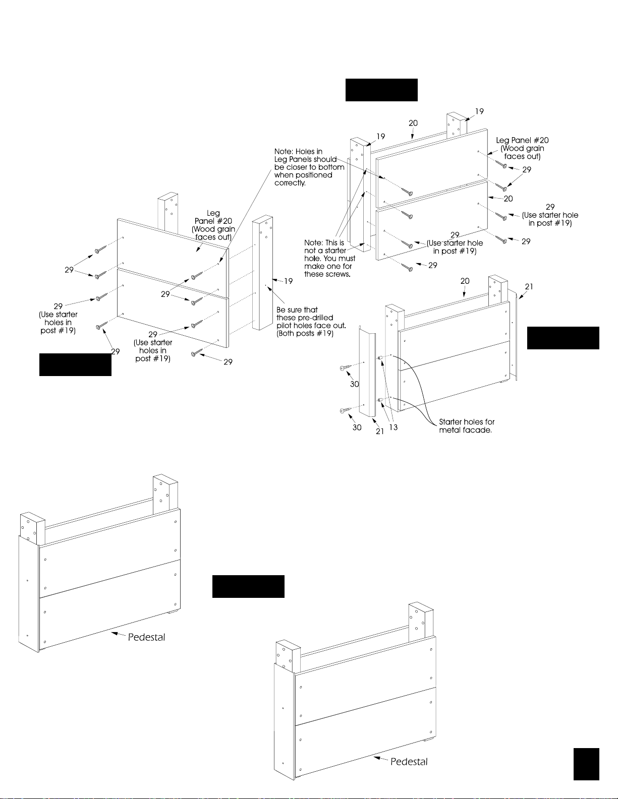
ASSEMBLE TWO LEG PEDESTALS AS FOLLOWS:
1. Begin by opening hardware kits and sort hardware.
Attach leg panels #20 to leg posts #19 using screws
#29. (Note: Set of screw holes should be closer to the
bottom of the panel when positioned correctly.) Start
by installing the top screws in bottom leg panel using
the pre-drilled starter holes in post #19. Square edge
of leg panel up to edge of post #19 then, install the
bottom two screws #29. Butt top leg panel #20 up to
bottom leg panel and secure in place using screws
#29. (See Figure 1a) Do not tighten screws #29 until
instructed to do so.
Be sure the wood grain faces out away from posts
#19.
Figure 1b
Figure 1a
Figure 1c
2. Attach inside leg panels #20 to leg posts #19 in same manner
as outside leg panels (See Figure 1b) Do not tighten screws
#29 until instructed to do so. Be sure the wood grain faces
out away from posts #19.
3. Attach metal leg facades #21 to pedestals. Attach leg facade
using two screws #30 and two plastic spacers #13. Locate leg
facade #21 by lining up the holes in the facade with the starter
holes in the leg post. See figure 1c.
4. Set up pedestals so that they face each other.
Figure 2
Page
3
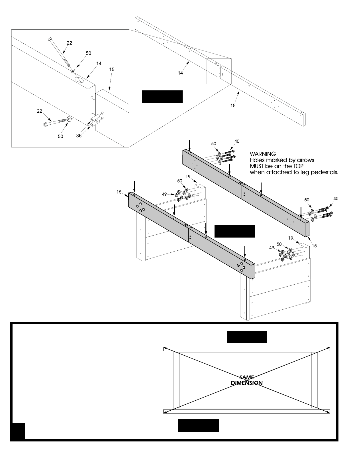
Figure 3
5. Attach a beam mate #15 to main beam #14 using
two bolts #22, two washers #50 and two dowel
connectors #36. See figure 3. Tighten bolts
tight. Repeat for other main beam #14.
6. Attach a beam assembly by
using four bolts #40, eight
washers #50, and four locknuts
#49 for each of the leg post #19.
Place one washer between the bolts
and beam and one between leg posts
and locknuts. Tighten these bolts
securely. (See figure 4)
7. Attach other beam #15 to the other side
the same way. (See figure 4)
Make sure the holes in the edge of the beams #15 are
on the top of the beams when attached.
8. Place the frame in its final location. Square
the base frame assembly by measuring
diagonally from the corner of one beam
to the opposite corner of the other beam.
(See Figure 5) Nudge the frame until both
diagonals are equal (within 1/16 inch). Go
back and tighten all loose screws, nuts
and bolts.
Figure 4
Top View
Page
4
Figure 5
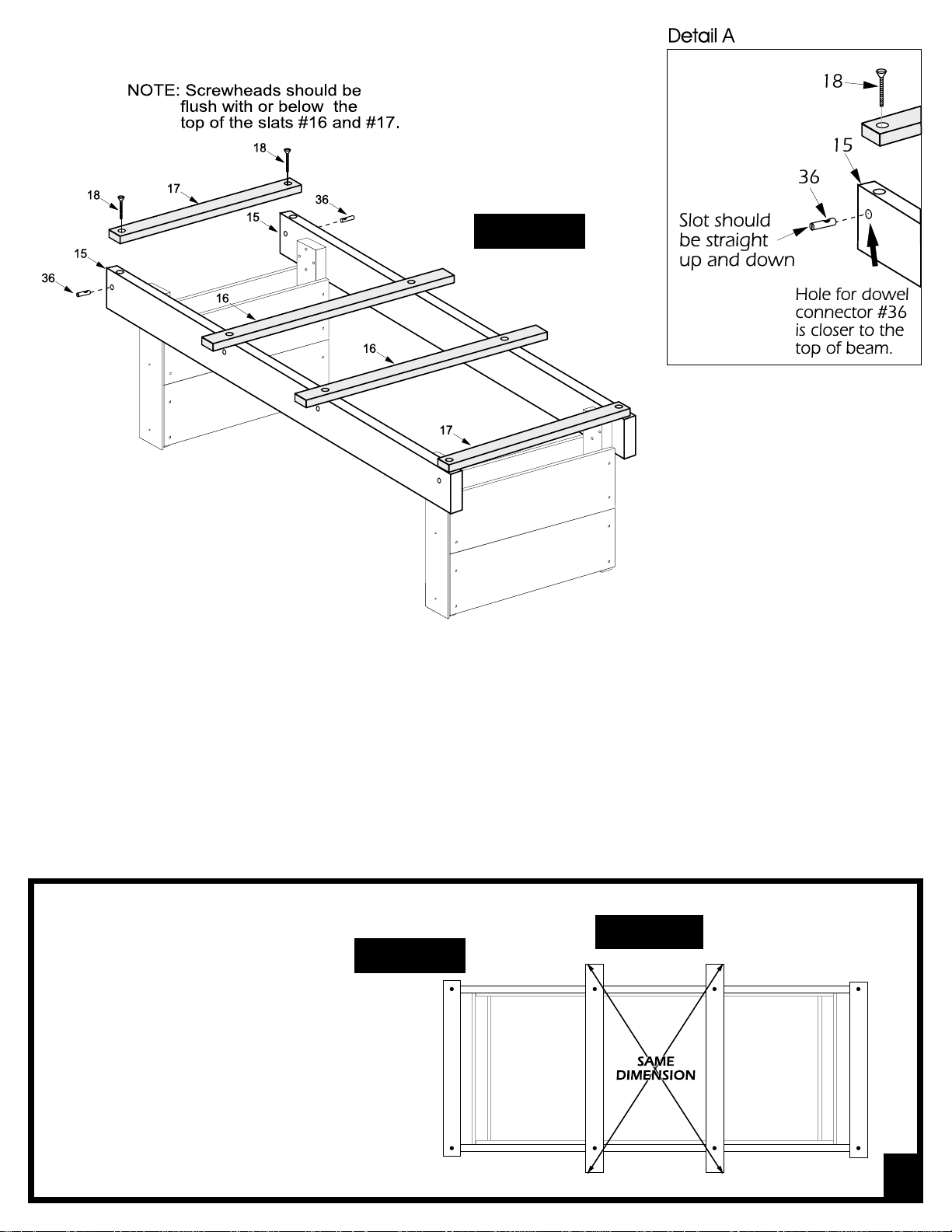
Figure 6
9. Place long slats #16 (50 inches long) and short slats #17 (36 inches long) across table from beam to beam as
shown in figure 6. Make sure to use the two shorter slats #17 on the ends of the beams and the two longer slats
#16 in the center as shown. Insert four dowel connectors #36 into the four holes in the side of each of the beams
#15 these holes should be closer to the top of the beams #4. (See Detail A). Attach the slats #16, and #17 to the
wooden beams #15 by placing screws #18 through the slats and into the dowel connectors #36 that are in the beams
#15 and tighten, make sure not to over tighten them. (See figure 4 and detail A))
HINT: When holes are lined up, the slot in the dowel connector should be vertical. After holes line up, insert screws
#18 into slats and down into dowel connectors. It is recommended to start the screws by hand and not forcing them
with power tools until you are sure threads are engaged properly. Do not tighten completely yet.
Top View
Figure 7
10. Square up the long slats #16 by measur-
ing diagonally, similar to the method
used earlier to square up base frame.
(See Figure 7) After squaring up slats,
tighten all the screws holding slats #16
and #17 to the beams.
Page
5
 Loading...