

Escalade Sports 2L-6540-00 User Manual

OWNER'S
MANUAL
MODEL NO.
P9900
527.25203
BALL RETURN KIT
Thank you for buying our product. We try hard to ensure that our products
are of high quality and free of problems, such as manufacturing defects or
missing parts. However, if you have any problems with your new product,
please
Escalade Sports at:
Please provide model number, serial number, and/or part number of the
product and/or part when you call or write. These numbers can be found on
the product, packaging, and/or in this Owner’s Manual.
If you are doing a new installation refer to the following
instructions. Use the hardware identifier that came in your
table. For replacement parts for your table see the Parts
List that came in your table. For replacement parts for
your ball return see the following.
DO NOT RETURN IT TO THE STORE! Call
TOLL FREE 1-800-426-1421
(THIS IS A CONSUMER ONLY NUMBER)
FAX: 812-467-1399
Or write us at:
CUSTOMER SERVICE DEPARTMENT
P.O. Box 889, Evansville, IN 47706
READ THESE
INSTRUCTIONS
CAREFULLY!
If you are doing a retrofit on an already assembled Lexington
Pool Table.
1 . Remove side aprons.
2 . Remove drop pockets.
3 . Determine which end of the beams are predrilled for ball return tray. See Figure 22.
4 . Perform steps 47 through 49 in this manual.
5 . Perform steps 53 through 61 in this manual.
6 . Perform steps 65 through 67 in this manual.
# PART# DESCRIPTION QTY.
21 2B-6016-00 1/4-20 LOCKNUT 2
22 801-9B 1/4-20 WASHER 2
25 801-54B 3/4 x 16 GA NAIL 30
37 801-4 #8 x 5/8 WASH HD SCREW 8
100 7P-6033-00 DOUBLE BACK TAPE 1
101 710-54 U-CLIP 2
102 701-166 1/4-20 x 3 HH BOLT 2
103 8S-6205-01 SUPPORT TUBE 1
104 3M-6139-00 BALL TRAY 1
105 3M-6140-00 BALL SCOOP 2
106 823-105L HD LFT CORNER POCKET 1
107 823-105R HD Right Corner Pocket 1
108 823-114L Side Left Pocket 1
109 823-114R Side Right Pocket 1
110 823-106 FT Corner Left Pocket 1
111 823-107 FT Corner Right Pocket 1
112 826-50U Ball Return Tube 4
2L-6540-00
IMPORTANT! READ THIS MANUAL ALL
THE WAY THROUGH BEFORE BEGINNING
TO PUT YOUR POOL TABLE TOGETHER!
THEN READ EACH STEP BEFORE
STARTING THAT STEP.
Tools Needed:
! Hammer (Claw Type) ! Putty Knife ! 3/8" Open End Wrench
! Needle Nose Pliers ! Tape Measure ! Hammer (Small Ball Peen Type)
! 7/16" Open End Wrench ! Sanding Block ! Carpenter's level or 36'' Straight Edge
! Standard Screwdriver ! Awl or 8d Nail ! ½" Open End Wrench
! Phillips Screwdriver ! Scissors or Sharp Knife ! Hairdryer
! Power Screwdriver (optional but very helpful)
! In addition to the assembly tools listed above, it would be useful to
have a rachet with 3/8, 7/16 and ½ socket.
NOTE: Rails are made with cushion rubber at a height that requires standard 2 ¼" diameter balls. Your dealer has
a complete line of Billiard Accessories.
NOTE: This table adds weight to any floor. Be sure floor can withstand this kind of weight. If floor sags, table will
be impossible to level.
THE SPRAY ADHESIVE USED FOR APPLYING PLAYFIELD CLOTH IS
EXTREMELY FLAMMABLE AND UNDER PRESSURE! CAREFULLY READ
CAUTIONS ON SPRAY ADHESIVE CONTAINER! KEEP OUT OF REACH OF
CHILDREN! DO NOT USE OR STORE NEAR HEAT SOURCE, FLAMES, SPARKS
OR WHEN SMOKING! WORK AREA MUST BE WELL VENTILATED. OPEN
DOORS AND WINDOWS WHEN USING SPRAY ADHESIVE.
2
30
21
1/8''
22
33
3
1
1
33
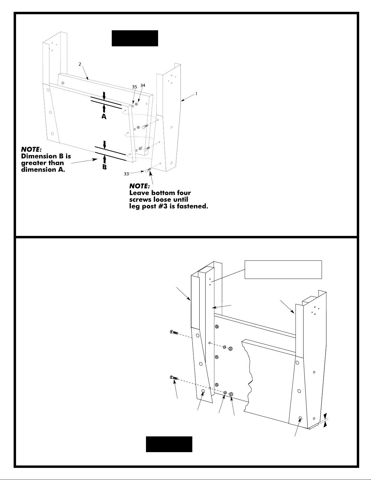
This set of holes grouped close
together goes toward the top.
Figure 1
1. Open hardware kits and sort
hardware into "like" groups using
hardware identifier provided in
your table manual. CAUTION:
Some steel parts may have
sharp edges.
2. Attach two wooden leg panels #2
(be sure wood grain faces out) to
the inside of two leg facades #1
using six screws #33, six washers
#35 and six locknuts #34 per leg
panel. Make sure that dimension
B is at the bottom of the leg panel.
(See Figure 1)
NOTE: Leave all four bottom
screws #33 loose until the leg
post #3 is installed. Leg post
#3 CANNOT be attached if
the four bottom screws #33 are
tight. Tighten finger tight only.
3. Repeat step 2 to put together other
leg assembly.
4a.Attach leg posts #3 to the inside face of
metal leg facades #1 on both leg assemblies (from steps 1 & 2). Use two
carriage bolts #30, two washers #22
and two locknuts #21 per leg post.
NOTE: There is a set of holes at one
end of the leg posts that are grouped
close together. Make sure that these
holes go to the top of the wooden
posts. About 1/8 inch of leg posts #3
will extend below the metal facade #1.
(Figure 2)
4b.Once the leg post is securely fastened,
tighten the four bottom screws #33 on
the leg panels.
Figure 2
3
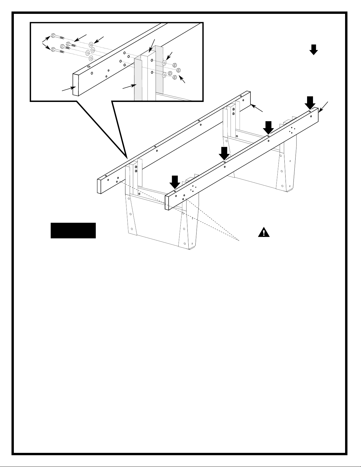
These holes are for ball return
attachment. Be sure both
beams #4 have these holes
at same end of table
27
WARNING:
MUST TOP
Holes marked by arrows
be on the when
attached to the legs!
40
All Washers
#23
3
#23
WARNING:
Holes marked by arrows
MUST TOP
be on the when
attached to the legs!
4
Figure 3
1
All locknuts
#26
4
4
CAUTION:
These holes are for ball return
attachment. Be sure both
beams #4 have these holes
at same end of table
5. Before starting this part of the assembly, orient
beam #4 with ball return attachment holes at the
same end of the table and the holes marked by
arrows in figure 3 facing up.
6. Attach wooden beams #4 to the leg assemblies (that
you just put together). Use two long bolts #27, two
short bolts #40, six washers #23 and four locknuts
#26 as shown.
NOTE: The two longer bolts #27 go through top
and bottom mounting holes in beam #4, metal
facade #1 and leg post #3. These bolts require a
washer between the bolt and beam #4 as well as
between leg post #3 and the locknut.
NOTE: The two shorter bolts #40 go through the
other two mounting holes in beam #4 and metal
facade #1. They only require a washer between the
bolt and beam #4.
4
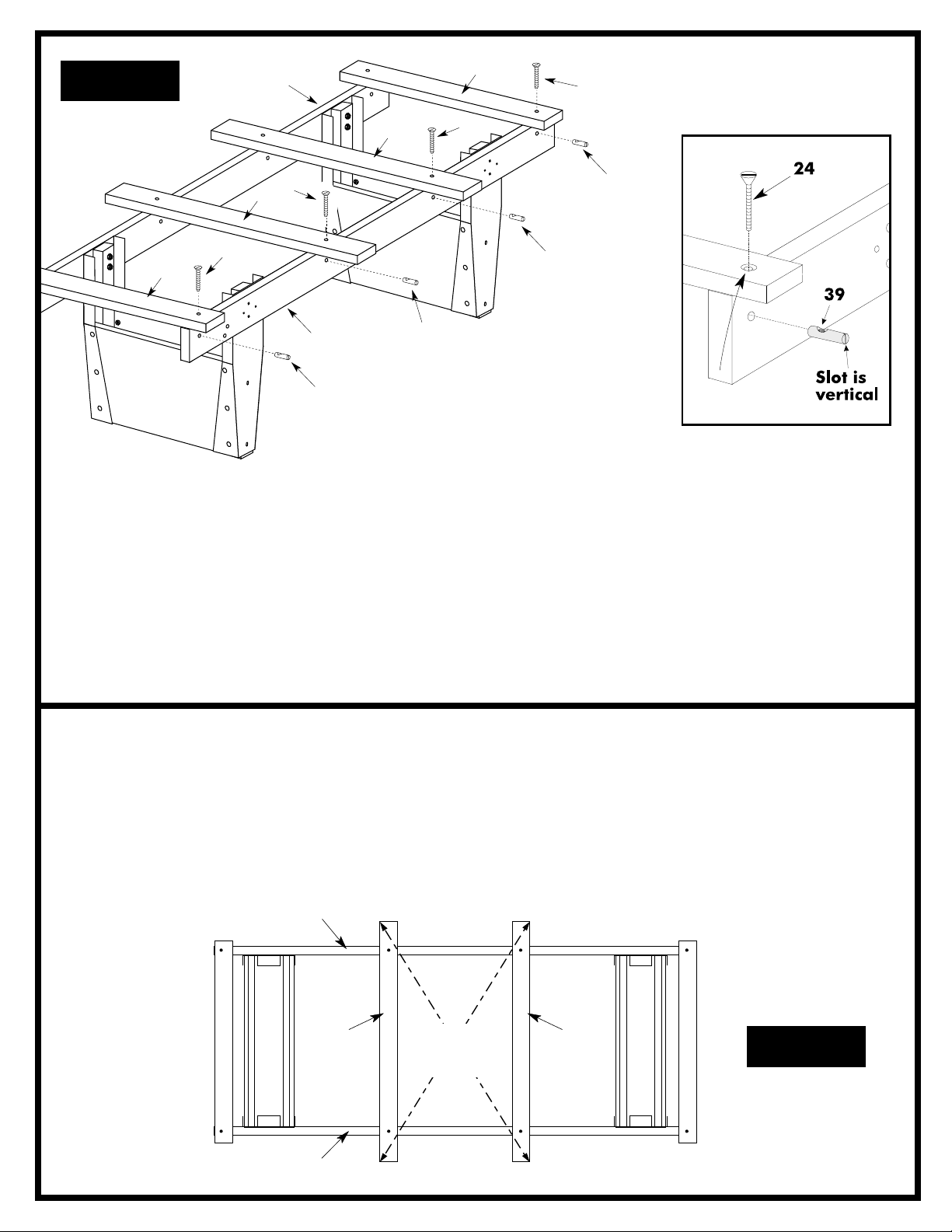
Figure 4
Countersink
goes up.
4
5
24
6
24
6
24
5
4
39
39
NOTE: Screwheads must
be flush or below the top of
the slats #5 and #6.
7. Place slats #5 and #6 across beams #4 as shown in
figure 4. Make sure the two shorter slats #5 go on the
ends of the beams and that the two longer slats #6 go
in the center as shown. The side of the slats with the
countersink around each hole faces up. (See detail A).
24
39
39
Detail A
Countersink
goes up.
8. Insert four dowel connectors #39 into the holes in
side of beams #4 just below the slats. Note that the
slot in the end of dowel connectors should be vertical.
(See Figure 4 and Detail A). Start screws #24 the
dowel connectors by hand until you are sure threads
are engaged properly. Do not force them with power
tools. Do not tighten screws completely yet.
9. Square up long slats #6 by measuring diagonally as
shown in figure 5. Diagonals should be the same
length within 1/8". Check to make sure the table is
square. If frame is not square, the adjustment can be
made by moving table beams #4 in opposite directions. Usually only a slight adjustment if any should
be required.
4
6
4
10. Once frame is square, tighten screws #24 holding
SAME
DIMENSION
(within 1/8")
slats to beams. Be sure the heads of screws #24
are flush with or below the top of the slats.
6
Figure 5
5
 Loading...