

Escalade Sports 2L-6437-03 User Manual
OWNER'SOWNER'S
OWNER'S
OWNER'SOWNER'S
MANUMANU
MANU
MANUMANU
ALAL
AL
ALAL
WARNING
FAILURE TO FOLLOW THESE
WARNINGS MAY RESULT IN
SERIOUS INJURY AND/OR
PROPERTY DAMAGE.
Owner must ensure that all
players know and follow these
rules for safe operation of the
unit.
! Do not dunk on this unit
! Do not hang from any part of the unit,
including the backboard, rim, or net.
! Do not slide, climb, or play on pole.
! Keep organic material away from
pole base. Grass, litter, etc. could
cause corrosion and /or deterioration.
! Check pole system twice a year for
signs of corrosion (rust, pitting,
chipping). Remove rust and/or loose
paint completely and repaint with
exterior enamel paint. If rust has
penetrated through the steel
anywhere, replace pole immediately.
! Check unit before each use for loose
hardware, excessive wear, and signs
of corrosion and repair before using.
! During play, use extreme caution to
keep players face away from the
backboard, rim, and net.
! Wear a mouthguard when playing to
avoid dental injuries.
! When adjusting height, keep hands
and fingers away from moving parts.
! During play, do not wear jewelry
(rings, watches, necklaces, etc.).
Objects may entangle in net.
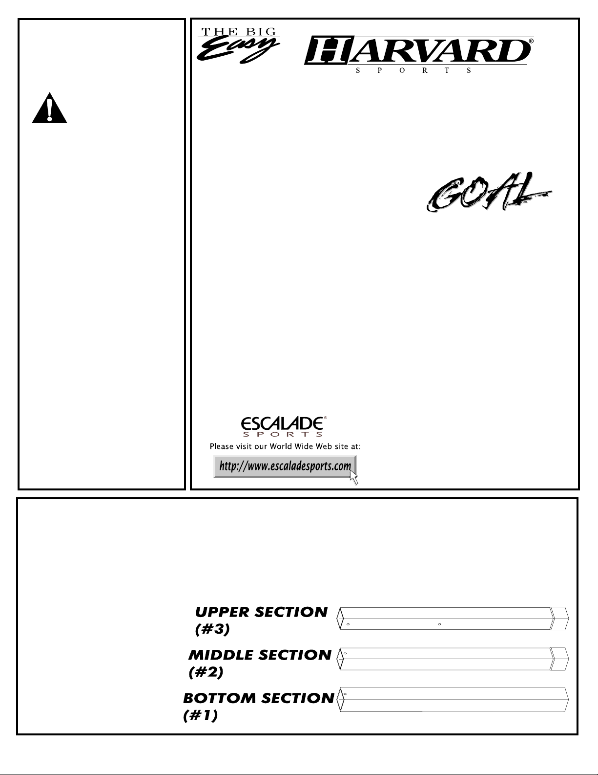
ADJUSTADJUST
ADJUST
ADJUSTADJUST
ABLE BASKETBALL POLEABLE BASKETBALL POLE
ABLE BASKETBALL POLE
ABLE BASKETBALL POLEABLE BASKETBALL POLE
WITHWITH
WITH
WITHWITH
PROPRO
“
PRO
PROPRO
STYLESTYLE
STYLE”
STYLESTYLE
BREAKAWAY
MODEL NUMBERS
B9771 & B9772
Thank you for buying our basketball pole. We try hard to ensure that our products are of high quality and
free of manufacturing defects and of missing parts. However, if you have any problems with your
basketball pole, such as a manufacturing defect or a missing part, please DO NOT RETURN IT TO THE
STORE. Call us at:
TOLL FREE 1-800-426-1421
(THIS IS A CONSUMER ONLY NUMBER)
FAX: (812) 467-1399
Or write us at:
CUSTOMER SERVICE DEPT., P.O. Box 889, Evansville, IN 47706
Please provide model number, serial number, and/or part number of the product and/or part when you call or
write. These numbers can be found on the product, packaging, or in this owner's manual.
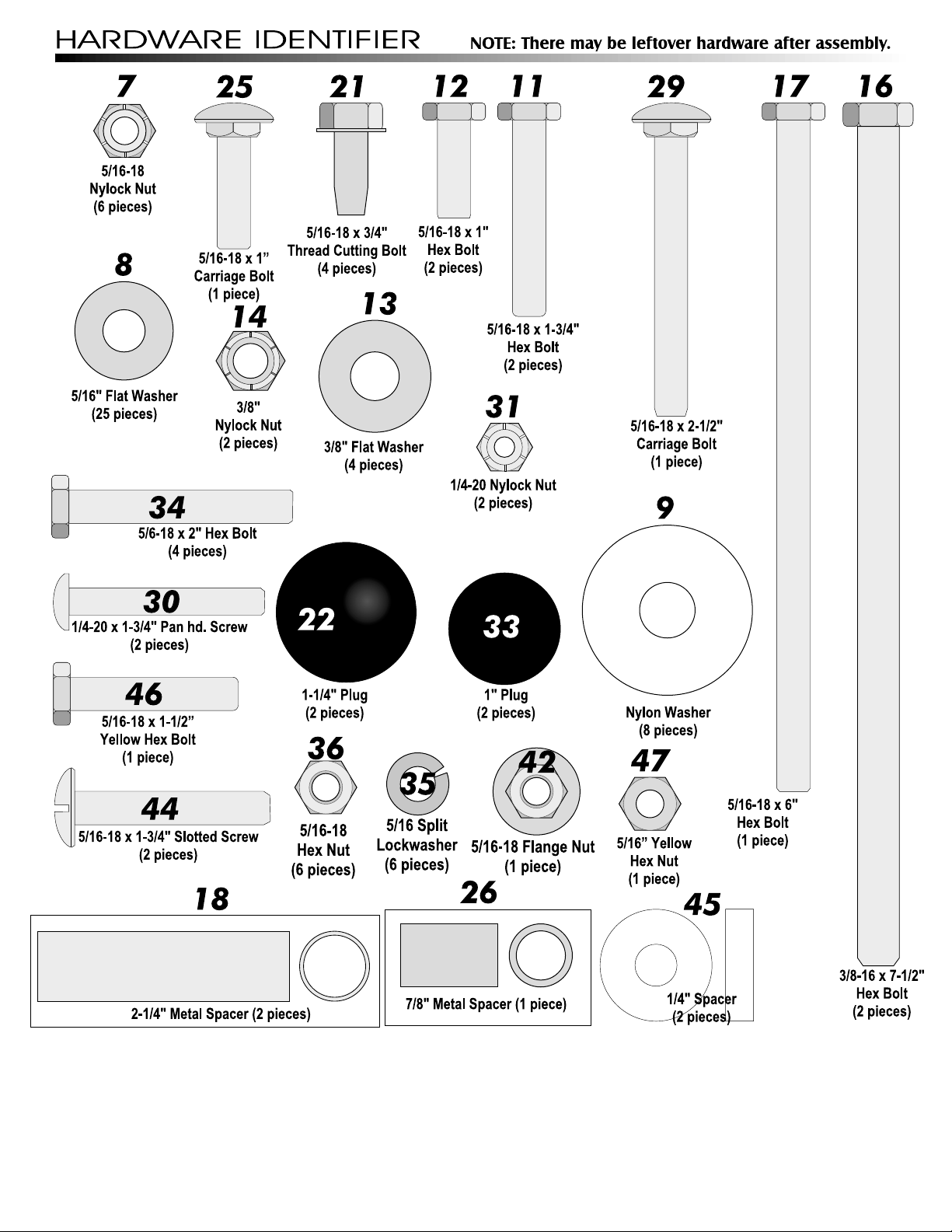
To make assembly of your basketball pole
easier, use the Hardware Identifier on page
2 to identify and sort all fasteners.
Do not tighten hardware until instructed to do so. If
hardware is tightened too soon, mounting holes may not
align and parts may not fit together. Leave locknuts
slightly loose until you are instructed to tighten them.
Read this manual all the way through before
starting to put up your pole. Then read each
step completely before beginning that step.
Some smaller parts may be
shipped inside larger tubes.
Check inside tubes before
assembling or ordering parts.
IMPORTANT! The three pole sections are different.
Use the illustration below to identify correct
sections (note the hole locations). Once sections
are seated together, you will NOT be able to
pull them apart!
2L-6437-03
To put up your pole, you will need the following tools:
" Post Hole Digger " Shovel " Level " Ladder " Tape Measure " Phillips and Flat Blade Screwdrivers
" Hammer " Gravel " Two adjustable wrenches OR two 1/2" Wrenches and One 9/16" Wrench
" Besides these tools, you will need approximately 1.6 cubic feet (three 80 lb. bags) of concrete to set your pole in the ground.
2
ASSEMBLY INSTRUCTIONS:
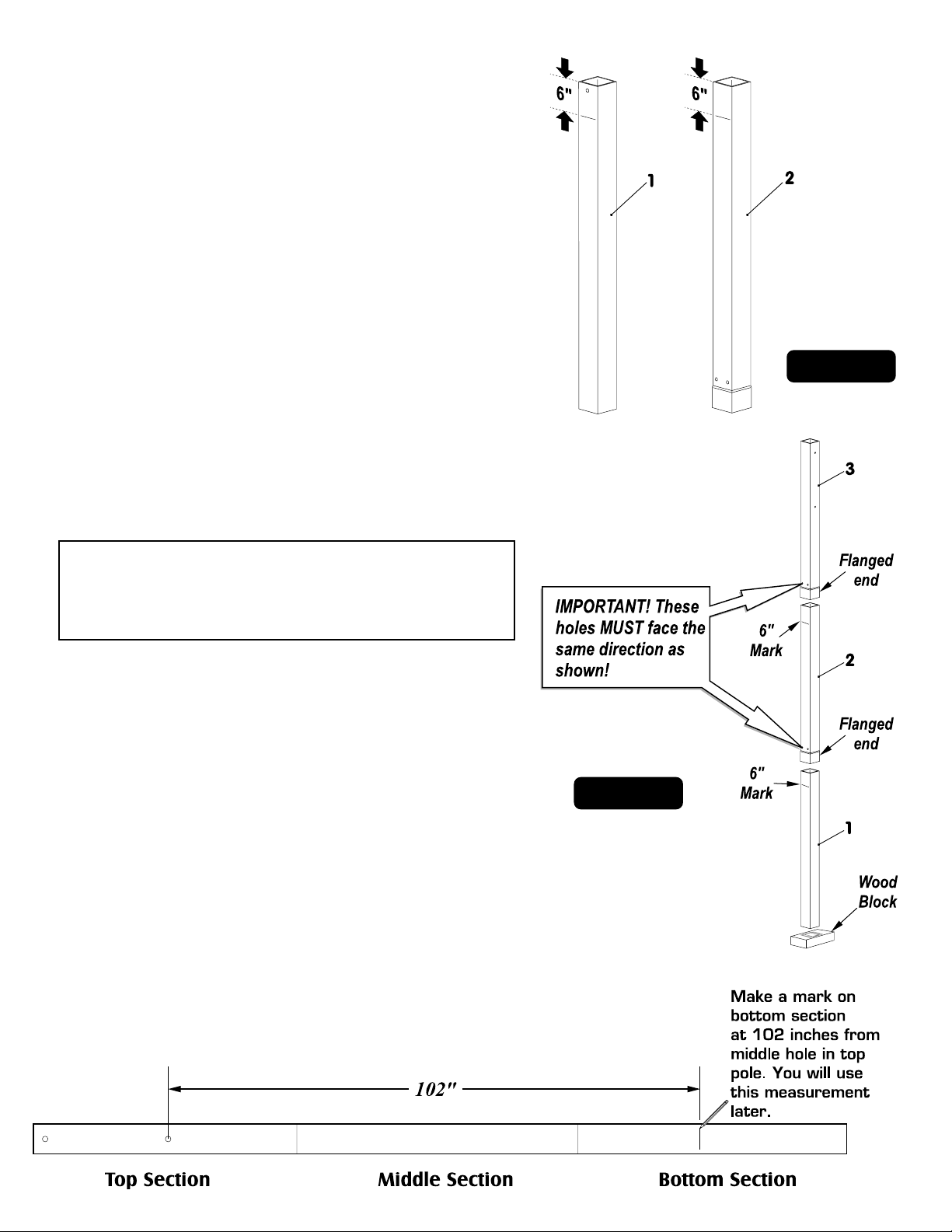
1. Before putting any of the pole tubes together, mark
bottom pole (#1) and middle pole (#2) 6 inches from their
top end. (On the bottom pole, the top end is the end with
the single hole in it). See Figure 1.
2. Align the upper pole (#3) with the middle pole (#2) making
sure the two holes near the flange of each pole face the
same direction as shown in figure 2, and slide them
together. Hit tubes on a piece of wood until there is no
more movement or until the bottom of the upper pole
reaches the 6" mark on the middle pole. Then align the
bottom pole (#1) with the middle pole (#2) (make sure the
weld seams in the poles line up) with your 6" mark on the
bottom pole toward the flange of the middle pole (#2) as
shown, and slide the sections together .
Figure 1
IMPORTANT! Make sure the pole sections are
aligned EXACTLY as shown in Figure 2 before
tapping them together! Once sections are seated
together, you will NOT be able to pull them apart!
3. Now lift tubes and pound them on a piece of wood to
secure. Hit the tubes until there is no more movement or
until the bottom end of the upper and middle tubes reaches
the 6 inch mark on the middle and lower tubes respectively.
Hit tubes a minimum of seven times. This is a friction-locking
joint and requires no hardware. NOTE: You may have to
turn poles upside down and pound top to completly
seat.
4. NOW MEASURE DOWN FROM MIDDLE HOLE IN TOP POLE
102 INCHES, AND MAKE A MARK ON BOTTOM POLE. YOU
WILL USE THIS MEASUREMENT IN STEP 20. SEE
ILLUSTRATION BELOW.
Figure 2
5. It may be helpful to lay the pole assembly at a diagonal
by placing one end on a bench or sawhorse with the
four holes in one side facing up (if necessary, lay the
pole on a piece of cardboard to prevent scratching).
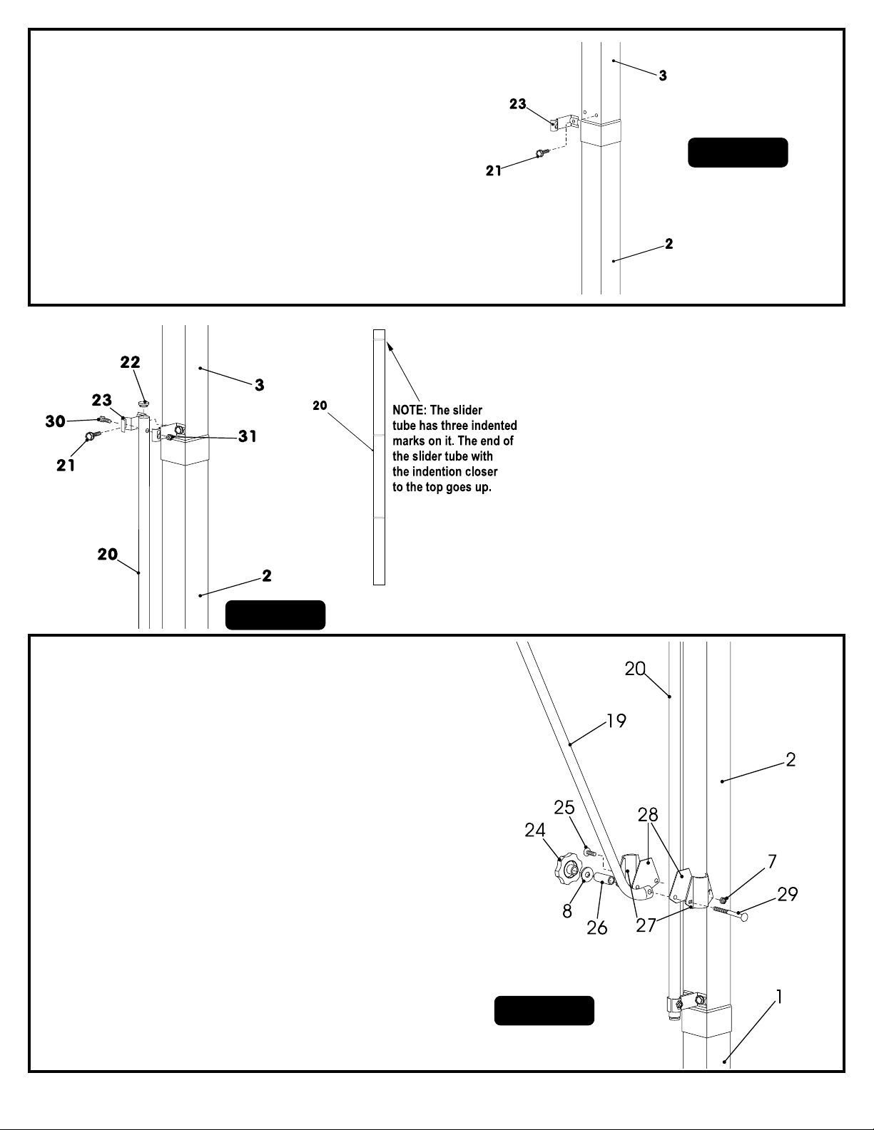
Attach one Stand-off Bracket (#23) to the right-hand hole
near the flange of upper pole (#3) as shown using a ¾"
thread-cutting bolt (#21). Attach another stand-off
bracket (#23) to the middle pole (#2) in the same manner.
See Figure 3.
Figure 3
6. Tap a plug (#22) into each end of the Slider
Tube (#20), and LOOSELY attach it to the
upper stand-off bracket by clamping it with
another stand-off bracket (#23) and
securing with a hex bolt (#30) and hex nut
(#31). NOTE: The tube has three
indentions on it. The end with the
indention closest to the top goes up.
Repeat this process at the lower stand-off
bracket. DO NOT TIGHTEN these screws
completely yet. Refer to Figure 4.
Figure 4
8. Assemble Slider Clamps (#27) to Slider Tube (#20). Be
sure the arrows on the Slider Clamp point up the tube.
Use carriage bolt (#25), two Slider Films (#28), and nylock
nut (#7) through inside holes. Tighten only until end of
bolt contacts plastic in nut. See Figure 5.
9. Assemble bent end of Pull Tube (#19) to Slider Clamp (#27)
with carriage bolt (#29), metal spacer (#26), flat washer
(#8), and knob (#24). Make sure the Pull Tube is between
Slider Films and the longest flat portion of the tube is
facing toward the slider tube as shown in Figure 5. Tighten
slider clamp securely. See Figure 5.
7. Fasten the remaining two stand-off
brackets to the upper and middle poles
with two ¾" thread-cutting bolts, tightened
securely. At this point, go back and tighten
all nuts securely. See Figure 4.
Figure 5
4
 Loading...