


PL160T/R,
PL260T/T and
PL460T/R
Installation Guide
ESCALA
REFERENCE
86 A1 55EW 01


ESCALA
PL160T/R, PL260T/T and
PL460T/R
Installation Guide
Hardware
July 2008
BULL CEDOC
357 AVENUE PATTON
B.P.20845
49008 ANGERS CEDEX 01
FRANCE
REFERENCE
86 A1 55EW 01

The following copyright notice protects this book under Copyright laws which prohibit such actions as, but not limited
to, copying, distributing, modifying, and making derivative works.
Copyright IBM, 2007-2008
Copyright © Bull SAS 2007-2008
Printed in France
Trademarks and Acknowledgements
We acknowledge the rights of the proprietors of the trademarks mentioned in this manual.
All brand names and software and hardware product names are subject to trademark and/or patent protection.
Quoting of brand and product names is for information purposes only and does not represent trademark misuse.
The information in this document is subject to change without notice. Bull will not be liable for errors
contained herein, or for incidental or consequential damages in connection with the use of this material.

Contents
Safety notices . . . . . . . . . . . . . . . . . . . . . . . . . . . . . . . . .v
About this publication . . . . . . . . . . . . . . . . . . . . . . . . . . . . . vii
How to send your comments . . . . . . . . . . . . . . . . . . . . . . . . . . . . . vii
Installing the model 03E/4A . . . . . . . . . . . . . . . . . . . . . . . . . .1
Chapter 1. Prerequisite tasks for the 03E/4A installation . . . . . . . . . . . . . . .3
Chapter 2. Installing your system in a rack . . . . . . . . . . . . . . . . . . . . .5
Installing the rack . . . . . . . . . . . . . . . . . . . . . . . . . . . . . . . . .5
Rack safety notices . . . . . . . . . . . . . . . . . . . . . . . . . . . . . . . .5
Determining the location . . . . . . . . . . . . . . . . . . . . . . . . . . . . . .7
Marking location by using the rack-mounting template . . . . . . . . . . . . . . . . . . .8
Marking the location without a rack-mounting template . . . . . . . . . . . . . . . . . .10
Installing the 14T/00, 14T/42 racks . . . . . . . . . . . . . . . . . . . . . . . . . .11
Completing a parts inventory . . . . . . . . . . . . . . . . . . . . . . . . . . .11
Positioning the rack . . . . . . . . . . . . . . . . . . . . . . . . . . . . . .11
Leveling the rack . . . . . . . . . . . . . . . . . . . . . . . . . . . . . . .12
Attaching the stabilizer brackets . . . . . . . . . . . . . . . . . . . . . . . . . .13
Attaching the rack to a concrete floor . . . . . . . . . . . . . . . . . . . . . . . . .14
Attaching the rack doors . . . . . . . . . . . . . . . . . . . . . . . . . . . .19
Connecting multiple racks with rack-to-rack attachment kit . . . . . . . . . . . . . . . .21
Attaching the rack to the concrete floor beneath a raised floor . . . . . . . . . . . . . . . .23
Connecting the power distribution system . . . . . . . . . . . . . . . . . . . . . . .27
Power distribution unit plus (PDU+) . . . . . . . . . . . . . . . . . . . . . . . . .27
Checking the ac outlets . . . . . . . . . . . . . . . . . . . . . . . . . . . . .27
Attaching the front or back ac electrical outlet . . . . . . . . . . . . . . . . . . . . . .28
Installing the ac outlet-mounting plates with ac outlets . . . . . . . . . . . . . . . . . .28
Installing the ac outlet-mounting plate without ac outlets . . . . . . . . . . . . . . . . .30
Connecting a dc power source . . . . . . . . . . . . . . . . . . . . . . . . . . .31
Installing the rack security kit . . . . . . . . . . . . . . . . . . . . . . . . . . .35
Installing the model in a rack . . . . . . . . . . . . . . . . . . . . . . . . . . . . .38
Attaching the mounting hardware to the rack . . . . . . . . . . . . . . . . . . . . . . .40
Installing the cable-management arm . . . . . . . . . . . . . . . . . . . . . . . . . .43
Chapter 3. Installing an 03E/4A with logical partitions . . . . . . . . . . . . . . .45
Checklist: Installing an 03E/4A with logical partitions . . . . . . . . . . . . . . . . . . . . .45
Cabling your server . . . . . . . . . . . . . . . . . . . . . . . . . . . . . . . .45
Cabling the server and the Hardware Management Console (HMC) . . . . . . . . . . . . . . .46
Cabling the server to access the Integrated Virtualization Manager . . . . . . . . . . . . . . . .49
Cabling the server to access the Operations Console . . . . . . . . . . . . . . . . . . . . .53
Setting up your console or interface and create logical partitions . . . . . . . . . . . . . . . . .58
Setting up the HMC and create logical partitions . . . . . . . . . . . . . . . . . . . . . .58
Setting up Virtual I/O Server, IVM, and logical partitions . . . . . . . . . . . . . . . . . . .59
Setting up the Operations Console, twinaxial console, or 5250 console and creating logical partitions . . . .59
Setting up your server to connect to service and support . . . . . . . . . . . . . . . . . . . .60
Installing operating systems . . . . . . . . . . . . . . . . . . . . . . . . . . . . . .60
Obtaining updates and upgrades . . . . . . . . . . . . . . . . . . . . . . . . . . . .60
Chapter 4. Installing a model 03E/4A without logical partitions . . . . . . . . . . . .61
Checklist: Installing an 03E/4A without logical partitions . . . . . . . . . . . . . . . . . . . .61
Cabling your server . . . . . . . . . . . . . . . . . . . . . . . . . . . . . . . .61
Cabling the server and the Hardware Management Console (HMC) . . . . . . . . . . . . . . .62
iii

Cabling the server to access the Advanced System Management Interface (ASMI) . . . . . . . . . . .65
Cabling the server to access the Operations Console . . . . . . . . . . . . . . . . . . . . .69
Setting up your console, terminal, or interface to manage your system . . . . . . . . . . . . . . .74
Setting up the HMC . . . . . . . . . . . . . . . . . . . . . . . . . . . . . . .74
Connecting to ASMI or SMS menus . . . . . . . . . . . . . . . . . . . . . . . . . .75
Setting up the Operations Console or 5250 console . . . . . . . . . . . . . . . . . . . . .75
Setting up your server to connect to service and support . . . . . . . . . . . . . . . . . . . .75
Installing operating systems . . . . . . . . . . . . . . . . . . . . . . . . . . . . . .75
Obtaining updates and upgrades . . . . . . . . . . . . . . . . . . . . . . . . . . . .76
Chapter 5. Common procedures (installing operating systems and obtaining updates)
for the model 03E/4A . . . . . . . . . . . . . . . . . . . . . . . . . . . . .77
Installing AIX . . . . . . . . . . . . . . . . . . . . . . . . . . . . . . . . . .77
Installing . . . . . . . . . . . . . . . . . . . . . . . . . . . . . . . . . . . .77
Installing Linux . . . . . . . . . . . . . . . . . . . . . . . . . . . . . . . . . .77
Configuring Electronic Service Agent on standalone AIX systems . . . . . . . . . . . . . . . . .77
Obtaining HMC machine code updates and upgrades . . . . . . . . . . . . . . . . . . . . .79
Obtaining firmware updates . . . . . . . . . . . . . . . . . . . . . . . . . . . . . .79
Updating the Virtual I/O Server’s firmware and device microcode through the Integrated Virtualization
Manager with an Internet connection . . . . . . . . . . . . . . . . . . . . . . . . . .79
Step 1. View the existing firmware level . . . . . . . . . . . . . . . . . . . . . . . .79
Step 2. Apply firmware and device microcode using the IVM . . . . . . . . . . . . . . . . .79
Step 3. Verify that the firmware updated correctly . . . . . . . . . . . . . . . . . . . .80
Updating the Virtual I/O Server’s firmware and device microcode through the Integrated Virtualization
Manager without an Internet connection . . . . . . . . . . . . . . . . . . . . . . . . .80
Step 1. Obtain the hardware microcode and firmware CD . . . . . . . . . . . . . . . . . .80
Step 1. Obtain the firmware update on CD . . . . . . . . . . . . . . . . . . . . . . .81
Step 2. Apply firmware and device microcode using the IVM . . . . . . . . . . . . . . . . .81
Step 3. Verify that the firmware updated correctly . . . . . . . . . . . . . . . . . . . .82
Obtaining operating system fixes . . . . . . . . . . . . . . . . . . . . . . . . . . . .82
Obtaining operating system fixes for AIX or Linux . . . . . . . . . . . . . . . . . . . . .82
Place the rack-mounted model 04E/8A, 03E/4A in the service position . . . . . . . . . . . . . . .82
Appendix. Accessibility features . . . . . . . . . . . . . . . . . . . . . . . . .87
Notices . . . . . . . . . . . . . . . . . . . . . . . . . . . . . . . . . . .89
Trademarks . . . . . . . . . . . . . . . . . . . . . . . . . . . . . . . . . . .90
Electronic emission notices . . . . . . . . . . . . . . . . . . . . . . . . . . . . . .90
Class A Notices . . . . . . . . . . . . . . . . . . . . . . . . . . . . . . . . .90
Terms and conditions . . . . . . . . . . . . . . . . . . . . . . . . . . . . . . . .94
iv Installation Guide for the 03E/4A, 07M/15, and 08M/25

Safety notices
Safety notices may be printed throughout this guide.
v DANGER notices call attention to a situation that is potentially lethal or extremely hazardous to
people.
v CAUTION notices call attention to a situation that is potentially hazardous to people because of some
existing condition.
v Attention notices call attention to the possibility of damage to a program, device, system, or data.
World Trade safety information
Several countries require the safety information contained in product publications to be presented in their
national languages. If this requirement applies to your country, a safety information booklet is included
in the publications package shipped with the product. The booklet contains the safety information in
your national language with references to the U.S. English source. Before using a U.S. English publication
to install, operate, or service this product, you must first become familiar with the related safety
information in the booklet. You should also refer to the booklet any time you do not clearly understand
any safety information in the U.S. English publications.
Laser safety information
The servers can use I/O cards or features that are fiber-optic based and that utilize lasers or LEDs.
Laser compliance
All lasers are certified in the U.S. to conform to the requirements of DHHS 21 CFR Subchapter J for class
1 laser products. Outside the U.S., they are certified to be in compliance with IEC 60825 as a class 1 laser
product. Consult the label on each part for laser certification numbers and approval information.
CAUTION:
This product might contain one or more of the following devices: CD-ROM drive, DVD-ROM drive,
DVD-RAM drive, or laser module, which are Class 1 laser products. Note the following information:
v Do not remove the covers. Removing the covers of the laser product could result in exposure to
hazardous laser radiation. There are no serviceable parts inside the device.
v Use of the controls or adjustments or performance of procedures other than those specified herein
might result in hazardous radiation exposure.
(C026)
CAUTION:
Data processing environments can contain equipment transmitting on system links with laser modules
that operate at greater than Class 1 power levels. For this reason, never look into the end of an optical
fiber cable or open receptacle. (C027)
CAUTION:
This product contains a Class 1M laser. Do not view directly with optical instruments. (C028)
CAUTION:
Some laser products contain an embedded Class 3A or Class 3B laser diode. Note the following
information: laser radiation when open. Do not stare into the beam, do not view directly with optical
instruments, and avoid direct exposure to the beam. (C030)
v

Power and cabling information for NEBS (Network Equipment-Building System)
GR-1089-CORE
The following comments apply to the servers that have been designated as conforming to NEBS
(Network Equipment-Building System) GR-1089-CORE:
The equipment is suitable for installation in the following:
v Network telecommunications facilities
v Locations where the NEC (National Electrical Code) applies
intrabuilding ports of this equipment are suitable for connection to intrabuilding or unexposed
The
wiring or cabling only. The intrabuilding ports of this equipment must not be metallically connected to the
interfaces that connect to the OSP (outside plant) or its wiring. These interfaces are designed for use as
intrabuilding interfaces only (Type 2 or Type 4 ports as described in GR-1089-CORE) and require isolation
from the exposed OSP cabling. The addition of primary protectors is not sufficient protection to connect
these interfaces metallically to OSP wiring.
Note: All Ethernet cables must be shielded and grounded at both ends.
The ac-powered system does not require the use of an external surge protection device (SPD).
The dc-powered system employs an isolated DC return (DC-I) design. The DC battery return terminal
shall not be connected to the chassis or frame ground.
vi Installation Guide for the 03E/4A, 07M/15, and 08M/25

About this publication
This book contains instructions to assist you in setting up your server. It is intended to ensure that the
system is running and is functional before you perform more complex and custom configurations.
For information about the accessibility features of this product, for users who have a physical disability,
see “Accessibility features,” on page 87.
How to send your comments
Your feedback is important in helping to provide the most accurate and highest quality information. If
you have any comments about this publication, send your comments to us. Be sure to include the name
of the book and the specific location of the text you are commenting on (for example, a page number or
table number).
vii

viii Installation Guide for the 03E/4A, 07M/15, and 08M/25

Installing the model 03E/4A
This book contains the tasks and information that is needed to set up your system in order to get it
running and into production.
Chapters 3 and 4 in this book have been broken down into two sections: installing an 03E/4A with
logical partitions and installing an 03E/4A without logical partitions. Each of those sections has a
separate checklist that you can use as a guide to assist you in setting up your system. The tasks listed
within each section and checklist are listed in chronological order. This will help give you an idea of what
tasks need to be completed when. Not all tasks that are listed need to be completed. That will depend on
your particular situation. For example, you might not be installing your system in a rack in which case
those tasks do not have to be completed.
See one of the following sections to continue:
v Chapter 3, “Installing an 03E/4A with logical partitions,” on page 45
v Chapter 4, “Installing a model 03E/4A without logical partitions,” on page 61
1

2 Installation Guide for the 03E/4A, 07M/15, and 08M/25

Chapter 1. Prerequisite tasks for the 03E/4A installation
Prior to setting up and installing your new system, complete the following tasks to ensure that you are
prepared for the installation.
1. If you are using a previously existing Hardware Management Console (HMC), you need to ensure
that your HMC is at the correct code level (7.3.2 or later).
To update your HMC code level, see Chapter 8, ”Updating, upgrading, and migrating your HMC
machine code″ in the Installation and Configuration Guide for the Hardware Management Console.
To view the PDF file of the Installation and Configuration Guide for the Hardware Management Console
(SA76-0084), approximately 3 MB in size, see sa76-0084.pdf
2. The System Planning Tool (SPT) helps you design a managed system that can support a specified set
of workloads. When you are done making changes to the system, you can save your work as a
system plan. You can import this file into your Hardware Management Console (HMC) or the
management partition for the Integrated Virtualization Manager (for systems that have multiple
logical partitions) and deploy the system plan to a managed system. When you deploy the system
plan, the HMC or the Integrated Virtualization Manager creates the logical partitions from the system
plan on the managed system
.
3

4 Installation Guide for the 03E/4A, 07M/15, and 08M/25

Chapter 2. Installing your system in a rack
Complete these tasks to install your system in a rack.
To install your system in a rack, perform the tasks in “Installing the model in a rack” on page 38.
Installing the rack
You might need to install the rack. Use the procedure in this section to perform this task.
Rack safety notices
You will need to read the rack safety notices before installing equipment. Use the procedure in this
section to perform this task.
Before installing a rack, rack features, or a system or expansion unit into a rack, read the following safety
information:
Attention: If you are installing equipment into a rack, the rack must comply with the Electronics
Industries Association (EIA) 310D specifications. If you do not have a rail kit designed for the equipment
in the rack, do not install the equipment into the rack as damage to the equipment or personal injury
could occur.
5
DANGER
Observe
the following precautions when working on or around your IT rack system:
v Heavy equipment–personal injury or equipment damage might result if mishandled.
v Always lower the leveling pads on the rack cabinet.
v Always install stabilizer brackets on the rack cabinet.
v To avoid hazardous conditions due to uneven mechanical loading, always install the heaviest
devices in the bottom of the rack cabinet. Always install servers and optional devices starting
from the bottom of the rack cabinet.
v Rack-mounted devices are not to be used as shelves or work spaces. Do not place objects on top
of rack-mounted devices.
v Each rack cabinet might have more than one power cord. Be sure to disconnect all power cords in
the rack cabinet when directed to disconnect power during servicing.
v Connect all devices installed in a rack cabinet to power devices installed in the same rack
cabinet. Do not plug a power cord from a device installed in one rack cabinet into a power
device installed in a different rack cabinet.
v An electrical outlet that is not correctly wired could place hazardous voltage on the metal parts of
the system or the devices that attach to the system. It is the responsibility of the customer to
ensure that the outlet is correctly wired and grounded to prevent an electrical shock.
CAUTION
v Do not install a unit in a rack where the internal rack ambient temperatures will exceed the
manufacturer’s recommended ambient temperature for all your rack-mounted devices.
v Do not install a unit in a rack where the air flow is compromised. Ensure that air flow is not
blocked or reduced on any side, front, or back of a unit used for air flow through the unit.
v Consideration should be given to the connection of the equipment to the supply circuit so that
overloading of the circuits does not compromise the supply wiring or overcurrent protection. To
provide the correct power connection to a rack, refer to the rating labels located on the
equipment in the rack to determine the total power requirement of the supply circuit.
v (For sliding drawers.) Do not pull out or install any drawer or feature if the rack stabilizer brackets
are not attached to the rack. Do not pull out more than one drawer at a time. The rack might
become unstable if you pull out more than one drawer at a time.
v (For fixed drawers.) This drawer is a fixed drawer and must not be moved for servicing unless
specified by the manufacturer. Attempting to move the drawer partially or completely out of the
rack might cause the rack to become unstable or cause the drawer to fall out of the rack.
(R001)
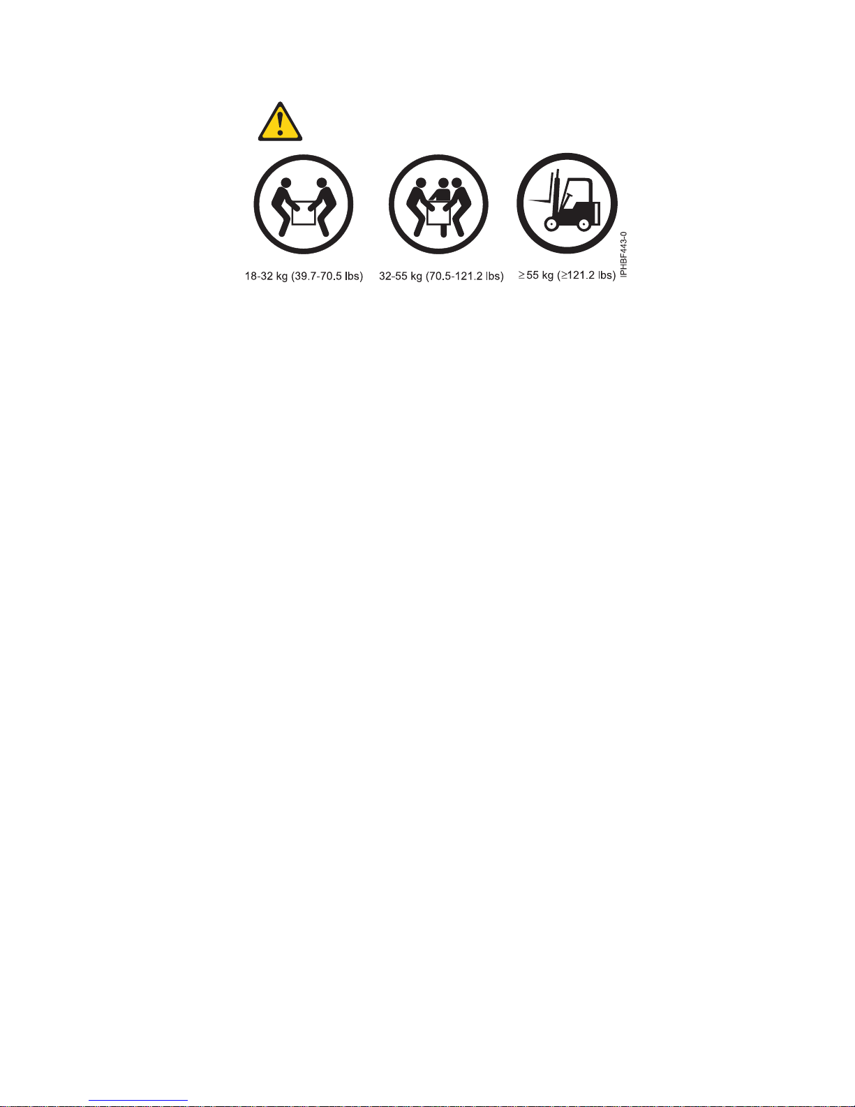
Lift precautions:
6 Installation Guide for the 03E/4A, 07M/15, and 08M/25
Determining the location
You might need to determine where to install the system in the rack. This section includes procedures so
that you can perform these tasks.
Before installing the system unit into a rack, complete the following steps:
1. Read the “Rack safety notices” on page 5.
2. Plan where you will place the units. Place the larger and heavier units in the lower part of the rack.
This system unit is four Electronic Industries Alliance (EIA) units high. An EIA unit is 1.75 in (44.45
mm) in height. The rack contains three mounting holes for each EIA unit of height. This system unit
therefore is 7 in high and covers 12 mounting holes in the rack.
3. If necessary, remove the filler panels to allow access to the inside of the rack enclosure where you
plan to place the unit.
Chapter 2. Installing your system in a rack 7
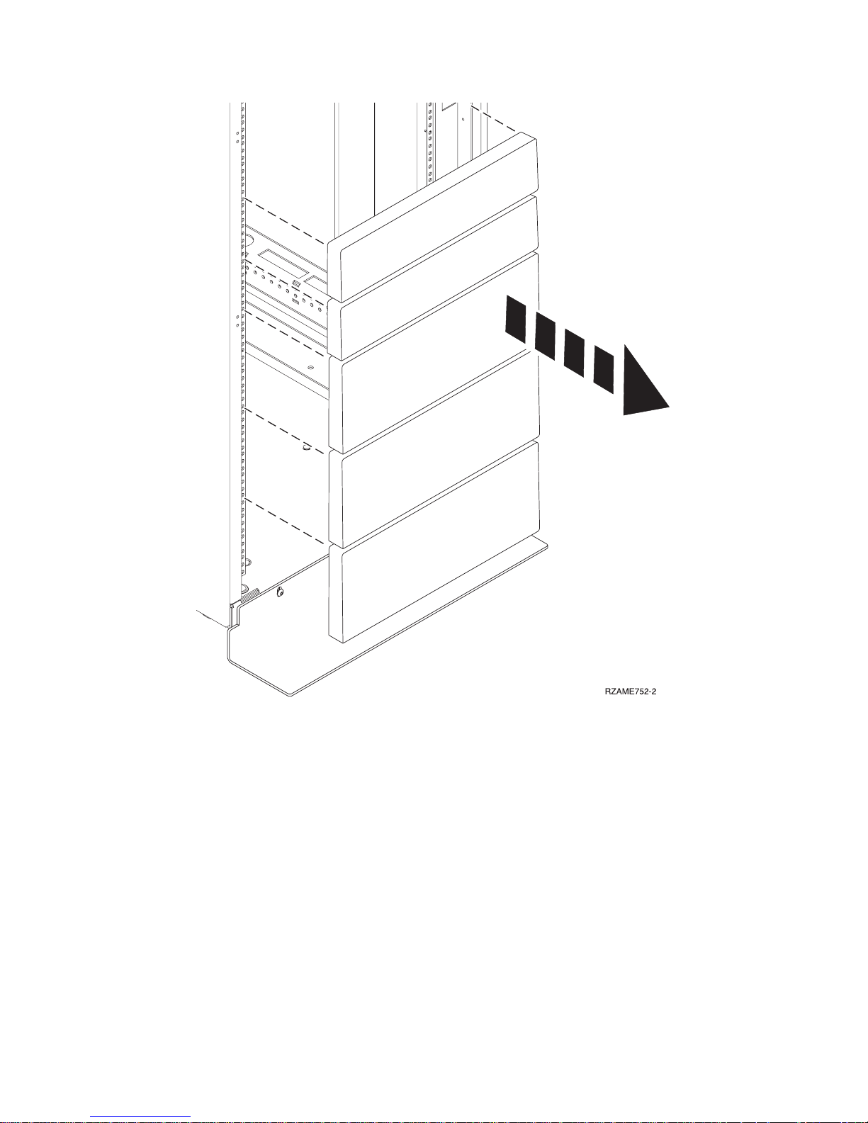
Figure 1. Removing the filler panels.
4. If necessary, remove the front and back rack doors.
5. Use the rack-mounting template to mark the location (see Mark location using the rack-mounting
template). If you do not have a rack-mounting template, following instructions for marking the
location without a template (see Mark the location without rack-mounting template).
Marking location by using the rack-mounting template
You might need to mark the installation location by using a rack-mounting template. Use the procedure
in this section to perform this task.
1. Using the rack-mounting template, determine where in the rack to place the unit. Install units in the
lower part of the rack first. Place larger and heavier units in the lower part of the rack.
8 Installation Guide for the 03E/4A, 07M/15, and 08M/25
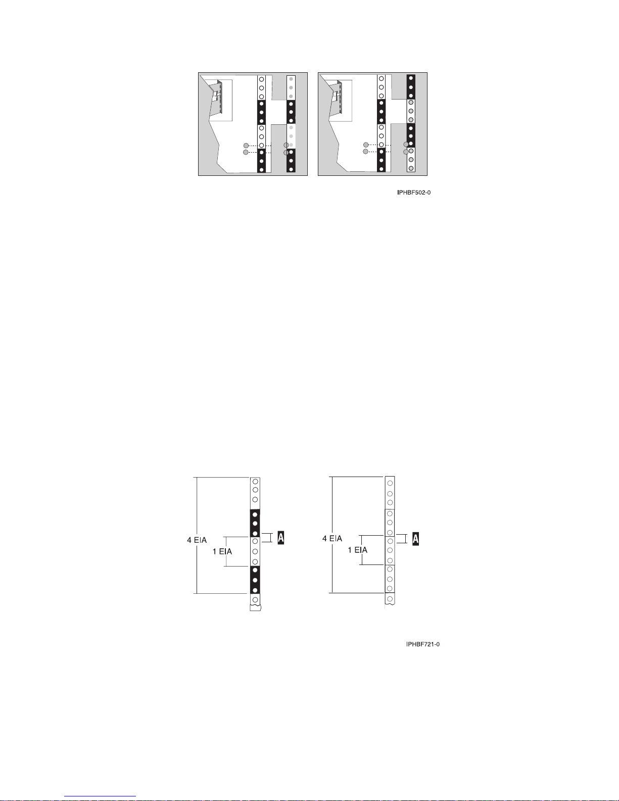
Figure 2. Rack-mounting template
Note: The front of the rack-mounting template has printed illustrations designed to help you identify
the mounting holes to be used when you add units to the rack. Do not use the rack-mounting
template without completing the following steps.
2. Note the following when using the rack-mounting template:
v Each black or white unit on the template is equal to one Electronic Industries Alliance (EIA) unit.
v An EIA unit is 1.75 in (44.45 mm) in height.
v The rack contains three mounting holes for each EIA unit of height.
v The EIA units that are illustrated on the template must be aligned with the EIA units located on the
rack.
v It is not necessary to align like-colored EIA units. For example, a black EIA unit on the
rack-mounting template can be aligned with a white EIA unit that are located on the rack.
v The template is two-sided. When using the template, ensure that the appropriate side of the
template is facing out.
Figure 3 shows one EIA unit and four EIA units. Depending on the rack manufacturer, the EIA units
might be separated either by color or by a line. Notice that the holes along the rail are not evenly
spaced. If your rack has no color or line separation between EIA units, assume that each EIA unit
begins where the hole spacing is closest together as shown by A in Figure 3.
Figure 3. EIA units
To use the rack-mounting template, complete the following steps:
a. Remove the protective coating from each adhesive strip located on the back of the rack-mounting
template. Lightly press the template into position on the rack. Ensure that both the left and right
sides are at the corresponding EIA locations.
Chapter 2. Installing your system in a rack 9

Note: The tabs on each side of the template show a notch to indicate the correct spacing between
the front flanges.
b. Locate the dots that are printed on the left and right side of the template. Place a self-adhesive dot
directly across from the template’s printed dots on or near the rack’s EIA numbering strip. You
will be using these dots to aid in correctly positioning the rail-alignment pins located on the front
of each rail.
c. Remove the rack-mounting template from the front of the rack. The front of your rack should now
contain dots.
d. Mount the rack-mounting template to the rack’s back EIA frame. Place the rack-mounting template
at the same EIA-numbered location that was used on the front of the rack.
e. Wrap a self-adhesive dot directly across from the template’s printed dots. Ensure that a portion of
the self-adhesive dot wraps around the rack frame so that it can be seen from the front of the rack.
f. Remove the rack-mounting template from the back of the rack. The back of your rack should now
contain dots that have been partially wrapped around the frame.
Marking the location without a rack-mounting template
You might need to mark the location without using a template. Use the procedure in this section to
perform this task.
To mark the installation location and install the nut clips into a rack without using the rack-mounting
template, complete the following steps:
1. Determine where in the rack to place the system. Install units in the lower part of the rack first. Place
larger and heavier units in the lower part of the rack. Record the EIA location. The system is four
Electronic Industries Alliance (EIA) units high. An EIA unit is 1.75 in (44.45 mm) in height. The rack
contains three mounting holes for each EIA unit of height. This system therefore is 7 in high and
covers 12 mounting holes in the rack.
2. Facing the front of the rack and working from the right side, place a self-adhesive dot next to the
bottom hole of the bottom EIA unit of the four you will be using for this system unit A in Figure 4 on
page 11.
Note: The self-adhesive dots are used to aid in identifying locations on the rack. If you do not have
the dots, use some other form of marking tool to aid you in identifying hole locations (for example,
tape, or a marker). You will need to identify the marked hole from both the front and back of the
rack.
3. Place another self-adhesive dot next to the bottom hole of the bottom EIA unit on the left side of the
rack.
4. Go to the back of the rack. On the right side, find the EIA unit that corresponds to the bottom EIA
unit marked on the front of the rack.
10 Installation Guide for the 03E/4A, 07M/15, and 08M/25
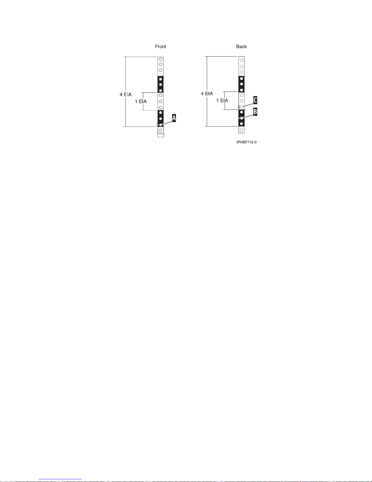
Figure 4. Marking holes on the front and back of the rack frame.
5. Place a self-adhesive dot at the middle hole of the bottom EIA unit, B in Figure 4.
6. Place a self-adhesive dot at the bottom hole of the next (higher) EIA unit, C in Figure 4.
7. Mark the corresponding holes on the left side of the rack.
Installing the 14T/00, 14T/42 racks
You might need to install the rack. Use the procedure in this section to perform this task.
If you are installing a rack security kit in this rack, see “Installing the rack security kit” on page 35 after
you have installed the rack.
Before installing a rack, read the “Rack safety notices” on page 5.
Completing a parts inventory
You might need to complete a parts inventory. Use the procedure in this section to perform this task.
If you have not done so, complete a parts inventory before installing the unit in the rack:
1. Locate the kitting report in an accessory box.
2. Ensure that you received all of the features that you ordered and all of the parts on the kitting report.
If there are incorrect, missing, or damaged parts, contact:
v Your reseller
Positioning the rack
You might need to position the rack. Use the procedure in this section to perform this task.
After the rack has been placed into its location on the floor, lock each caster by tightening the locking
screw. See the following illustration for the locking screw location. Remove all of the tape and packing
materials from the rack.
Chapter 2. Installing your system in a rack 11
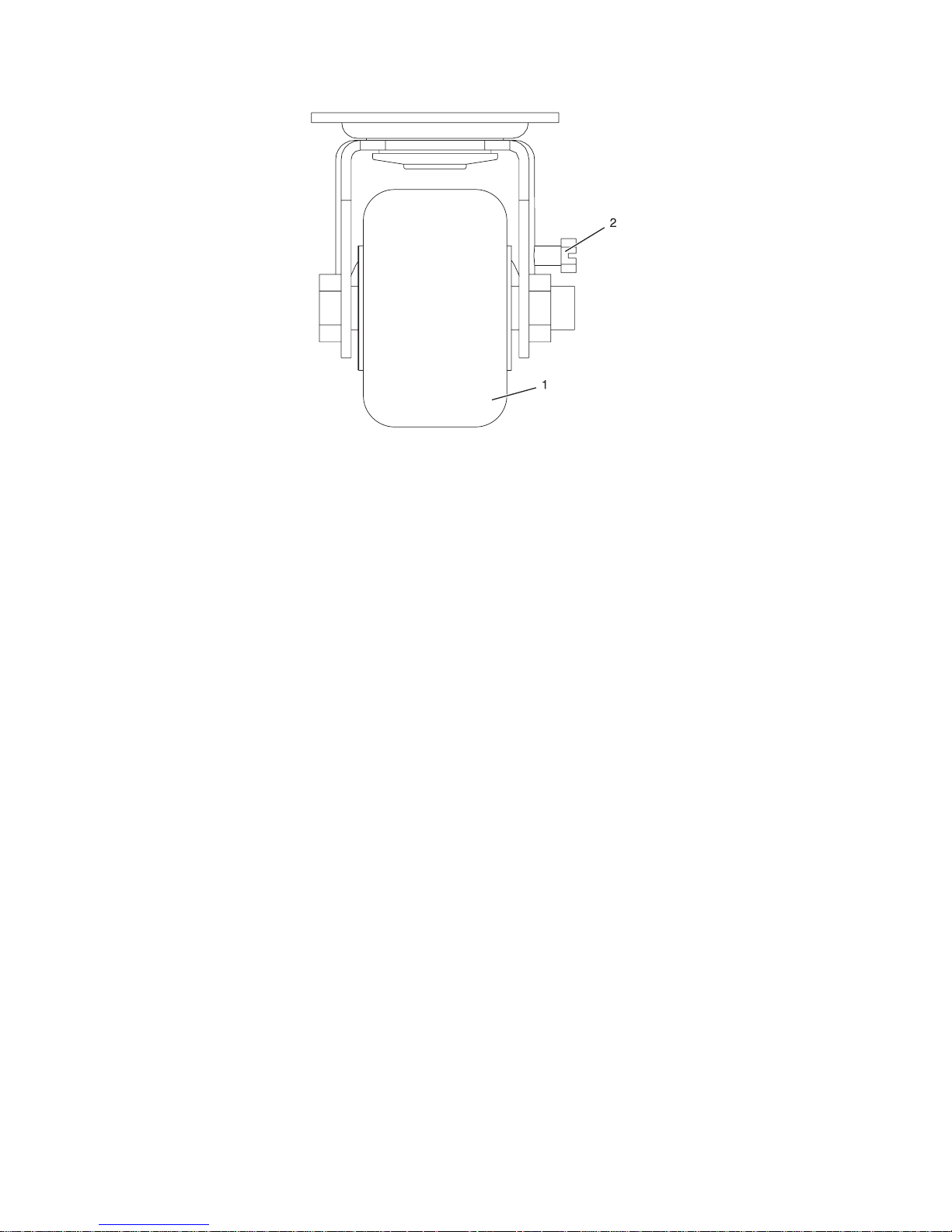
1 Caster
2 Locking screw
Figure 5. Tightening the locking screw.
Use the following to determine the next step:
v If the rack is being bolted to a concrete floor, go to “Attaching the rack to a concrete floor” on page 14.
v If the rack is being bolted to a concrete floor beneath a raised floor, go to “Attaching the rack to the
concrete floor beneath a raised floor” on page 23.
v If the rack is not being attached to the floor, go to “Leveling the rack.”
Leveling the rack
You might need to level the rack. Use the procedure in this section to perform this task.
To level the rack, complete the following steps:
1. Loosen the jam nut on each leveling foot.
2. Rotate each leveling foot downward until it contacts the surface on which the rack is placed.
3. Adjust the leveling feet downward as needed until the rack is level. When the rack is level, tighten
the jam nuts against the base.
12 Installation Guide for the 03E/4A, 07M/15, and 08M/25
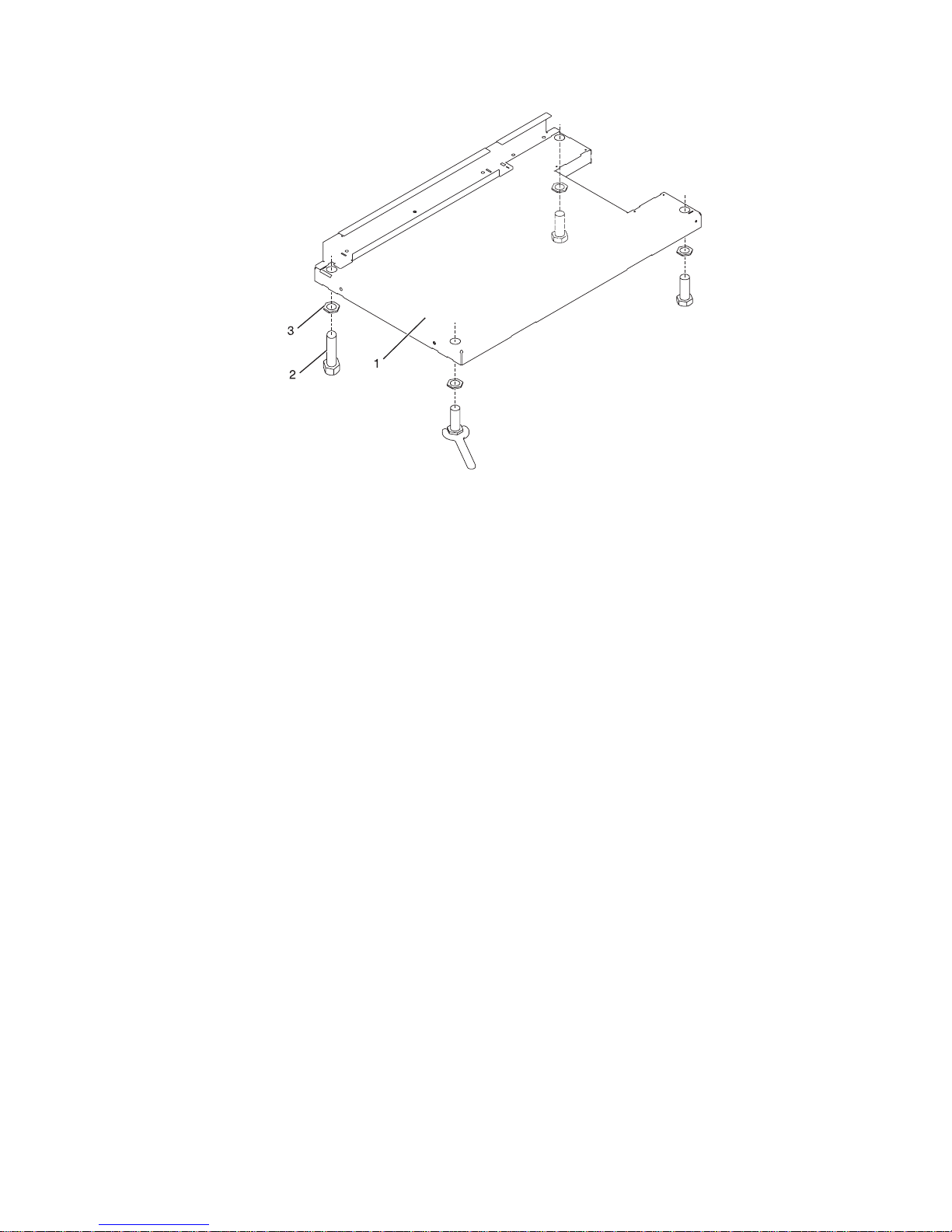
1 Rack Front (base)
2 Leveling Foot (quantity 4)
3 Jam Nut (quantity 4)
Figure 6. Adjusting the leveling feet.
Attaching the stabilizer brackets
You might need to attach the stabilizer brackets to the rack. Use the procedure in this section to perform
this task.
If the front or back ac electrical outlets are going to be installed in the rack, you cannot attach the
stabilizer brackets. The rack must be bolted to the floor. Stabilizer brackets are used only if you will not
be bolting the rack to the floor. If you are going to bolt the rack to the floor, go to “Attaching the rack to
a concrete floor” on page 14.
To attach the stabilizer brackets to the bottom of the rack, do the following:
Note: Before installing the stabilizer brackets, see “Attaching the front or back ac electrical outlet” on
page 28 for instruction on installing the ac outlet-mounting plates.
1. Align the slots of one of the stabilizer brackets with the mounting holes at the bottom front of the
rack.
2. Install the two mounting screws.
3. Ensure that the base of the stabilizer bracket rests firmly on the floor. Use the Allen wrench that was
supplied with the rack to tighten the mounting screws alternately until they are tight.
Chapter 2. Installing your system in a rack 13
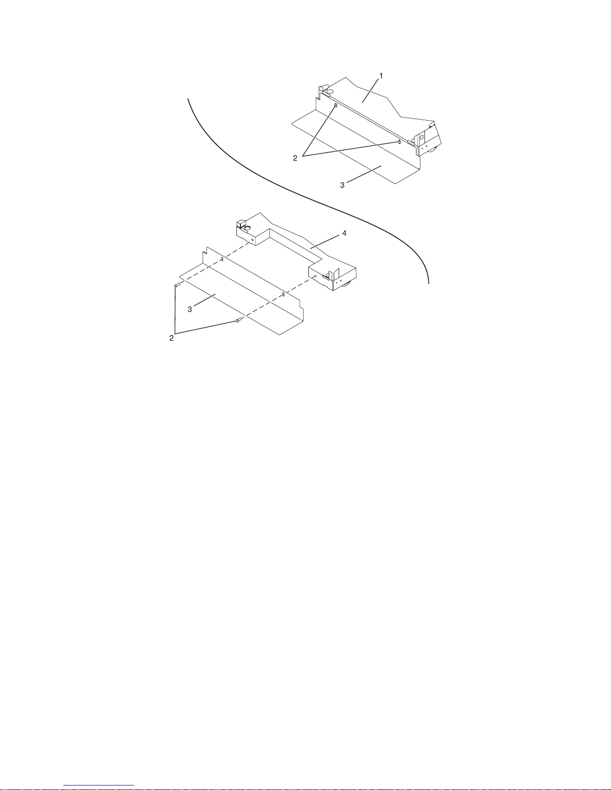
1 Rack front (base) 3 Stabilizer bracket
2 Stabilizer mounting screws 4 Rack rear (base)
Figure 7. Attaching the stabilizer brackets.
4. To install the second stabilizer bracket on the back of the rack, repeat steps 1 through 3.
Attaching the rack to a concrete floor
You might need to attach the rack to a concrete floor. Use the procedure in this section to perform this
task.
Obtain the services of a mechanical contractor to attach the rack-mounting plates to the concrete floor.
The mechanical contractor must determine that the hardware being used to secure the rack-mounting
plates to the concrete floor is sufficient to meet the requirements for the installation.
To attach the rack to a concrete floor, do the following:
1. Put the rack in its predetermined location, and tighten the locking screws on the casters.
2. If they are installed, remove the top, left, and right trim panels. The trim panels are held in place
with spring clips. See the following illustration.
14 Installation Guide for the 03E/4A, 07M/15, and 08M/25
1 Rack chassis 4 Right-side trim panel
2 Top trim panel 5 Spring clip
3 Left-side trim panel
Figure 8. Removing the trim panels.
3. If they are installed, remove the front and back doors. After the rack doors have been removed, go to
the next substep. To remove a rack door:
a. Unlock and open the door.
b. Grasp the door firmly with both hands and pull it away from the hinges.
4. Locate the hardware mounting kit and the two mounting plates. Refer to the following illustration
when reviewing the contents of the hardware mounting kit. The hardware mounting kit contains the
following:
v 4 Rack-mounting bolts
v 4 Thin washers
v 8 Plastic isolator bushings
v 4 Thick washers
v 4 Spacers
5. If you are installing an ac-powered rack, temporarily install the lower plastic isolator bushings to
help you locate the mounting locations for the stabilizer bracket. After the stabilizer bracket has been
Chapter 2. Installing your system in a rack 15
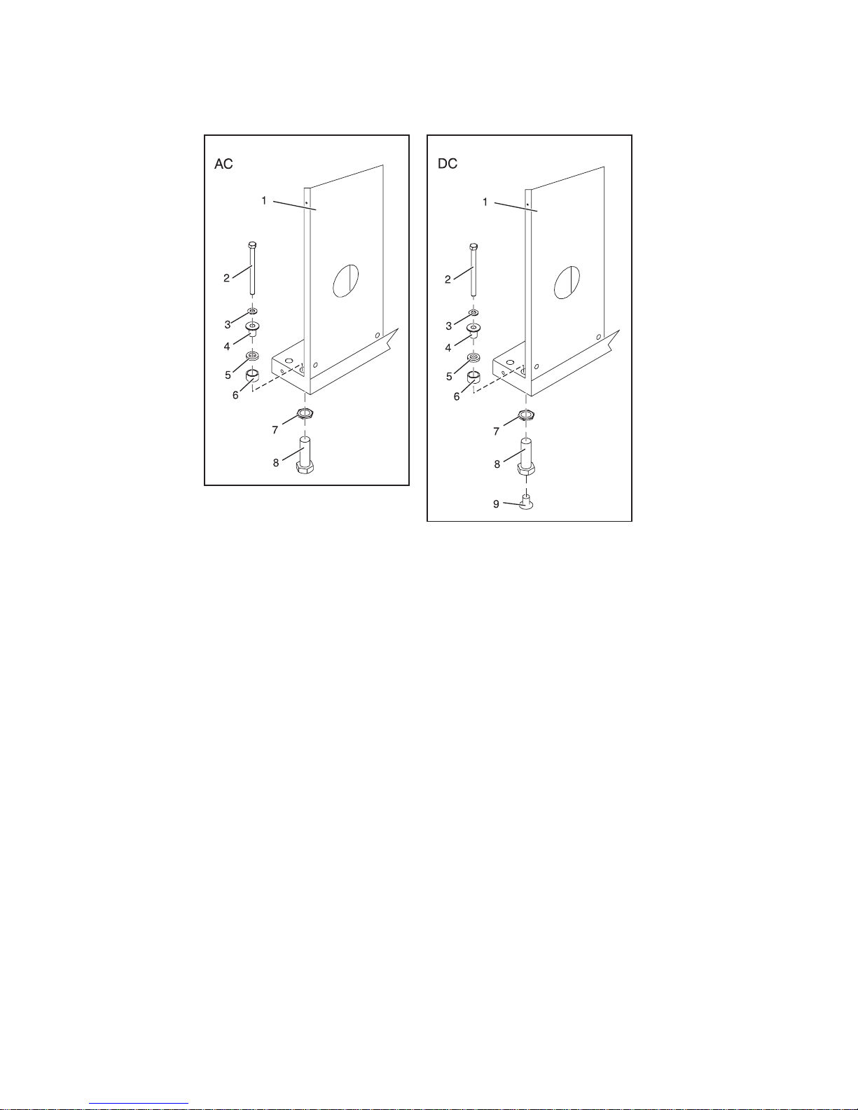
correctly located, remove the lower plastic isolator bushings.
Figure 9. Installing ac-power mounting plates
1 Rack chassis 7 Jam nut
2 Rack-mounting bolt 8 Leveling foot
3 Thin washer 9 Lower plastic isolator bushing (used
only on dc powered systems)
4 Top plastic isolator bushing AC Typical leveling foot installation for
an ac-powered rack
5 Thick washer DC Typical leveling foot installation for
an dc-powered rack
6 Spacer
6. Position the two mounting plates in the approximate mounting location under the rack.
7. Create a rack-mounting bolt assembly by adding the following items, in the order listed, to each
rack-mounting bolt.
a. Thin washer
b. To p plastic isolator bushing
c. Thick flat washer
d. Spacer
8. Insert a rack-mounting bolt assembly through each of the leveling feet.
9. Reposition the rack-mounting plates under the four rack-mounting bolts so that the mounting bolts
are centered directly over the threaded bolt holes.
10. Turn the rack-mounting bolts four complete turns into the mounting plate’s threaded bolt holes.
16 Installation Guide for the 03E/4A, 07M/15, and 08M/25
1 Rack-mounting bolt 7 Leveling foot
2 Thin washer 8 Lower plastic isolator bushing (Used
only on dc powered systems)
3 Top plastic isolator bushing 9 Mounting plate
4 Thick washer 10 Threaded hole (Used to secure the
rack to stabilizer bracket.)
5 Spacer 11 Anchor bolt hole
6 Jam nut 12 Traced pattern (Pattern to be traced
onto the floor using the stabilizer
bracket as a template)
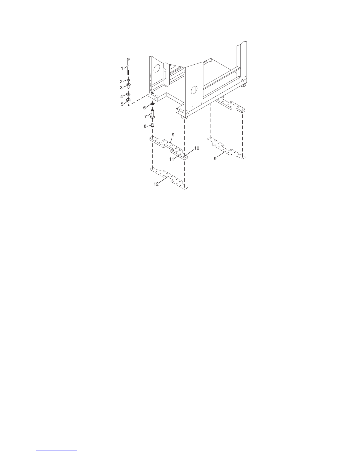
Figure 10. Securing the rack to the floor.
11. Mark the floor around the edges of both stabilizer brackets.
12. Mark the plate bolt-down holes that are accessible through the opening in the rear of the rack.
13. Remove the rack-mounting bolt assemblies.
14. If you are installing an ac-powered rack, remove the bottom isolator bushing from each of the
leveling feet.
15. Remove the stabilizer brackets from the marked locations.
16. Loosen each of the locking screws on the casters.
17. Move the rack so that it is clear of both areas that were marked on the floor for the stabilizer bracket
locations.
18. Reposition the stabilizer brackets within the marked areas.
19. Mark the floor at the center of all holes in both stabilizer brackets.
20. Remove the two rack-mounting plates from the marked areas.
21. At the marked location of the threaded rack-mounting bolt holes, drill four clearance holes into the
concrete floor. Each clearance hole should be approximately 1-inch deep. This depth allows the
rack-mounting bolts enough room to protrude past the thickness of the stabilizer brackets.
Chapter 2. Installing your system in a rack 17
Note: You must use a minimum of two anchor bolts for each rack-mounting plate to securely attach
the plate to the concrete floor. Because some of the holes in each rack-mounting plate might align
with concrete reinforcement rods embedded in the concrete, some of the rack-mounting plate holes
might not be usable.
22. Select at least two suitable hole locations for each stabilizer bracket bolt. The selected locations
should be as close to the threaded bolt holes as possible. Be sure that the holes selected at the back
of the rack are accessible. Drill holes at the selected locations into the concrete floor.
23. Position the stabilizer brackets over the concrete anchors.
24. Securely bolt the front stabilizer bracket to the concrete floor.
25. Position the stabilizer bracket over the concrete anchors.
26. Securely bolt the back stabilizer bracket to the concrete floor.
Note: The size of the anchor bolts and concrete anchors must be determined by the mechanical
contractor who will be installing the rack-mounting plate.
27. Position the rack over the stabilizer bracket.
28. Insert each of the stabilizer bracket bolts through a flat washer, a plastic isolator bushing and a thick
washer, and through a leveling foot.
29. Align the four stabilizer brackets bolts with the four tapped holes in the two mounting plates and
turn three to four rotations.
30. Tighten the locking screw on each caster.
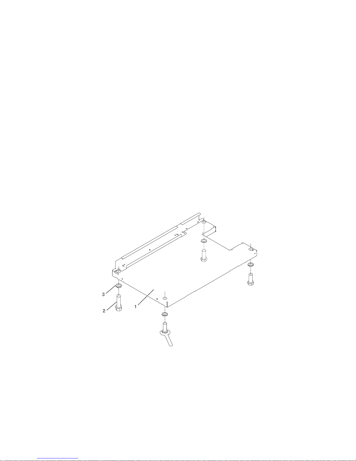
31. Adjust the leveling feet downward as needed until the rack is level. When the rack is level, tighten
the jam nuts against the base of the rack.
Figure 11. Adjusting the leveling feet.
32. If you have multiple racks that are connected in a suite (bolted to each other), go to “Connecting
multiple racks with rack-to-rack attachment kit” on page 21. Otherwise, torque the four bolts to
40-50 ft-lbs (54-67 nm).
18 Installation Guide for the 03E/4A, 07M/15, and 08M/25
1 Rack front (base)
2 Leveling foot (quantity 4)
3 Jam nut (quantity 4)
33. If you are not installing doors on your rack, install the top, left, and right trim panel.
34. Connect the power distribution system as described in “Connecting the power distribution system”
on page 27.
35. After all racks are bolted down, go to “Attaching the front or back ac electrical outlet” on page 28.
36. If you are not going to attach a front electrical outlet and you are installing rack doors, go to
“Attaching the rack doors”
Attaching the rack doors:
You might need to attach the rack doors. Use the procedure in this section to perform this task.
Depending on the model of the rack, the front door of a rack might be an optional feature. If your system
already has the front door installed, or does not have a front door to install, skip this step.
Figure 12. Attaching the rack door
Attaching a rack front door:
You might need to attach a front door to a rack. Use the procedure in this section to perform this task.
To install a rack front door to open from right to left, follow the installation steps described in “Attaching
a high-perforation front door” on page 20.
To install a rack front door to open from left to right, refer to the previous illustration, and perform the
following steps:
1. Read the “Rack safety notices” on page 5.
2. Remove the door latch and cover plate and reinstall them on the opposite side of the door.
3. Remove the door hinges and reinstall them on the opposite side of the door.
4. Install the rack latch on the opposite side of the rack.
5. Align the front door with the hinge pins, and lower the door into position.
Chapter 2. Installing your system in a rack 19
6. Adjust the latch so the door latches securely.
Removing a rack door:
You might need to detach a front door to a rack. Use the procedure in this section to perform this task.
1. Read the “Rack safety notices” on page 5.
2. Raise the front door off the hinge pins.
Attaching
a high-perforation front door:
You might need to attach a front door to the rack. Use the procedure in this section to perform this task.
To install the high-perforation front door, do the following:
1. Read the “Rack safety notices” on page 5.
2. Remove the top, left, and right trim panels.
Figure 13. Removing the trim panels.
20 Installation Guide for the 03E/4A, 07M/15, and 08M/25
1 Rack chassis
2 Top trim panel
3 Left side trim panel
4 Right side trim panel
5 Spring clip

3. Install the door latch on the right and the door hinges on the left.
4. For a high-perforation front door, align the door over the rack hinge, then move up the hinge pin on
the door, and lower the hinge pin into the hinge.
5. Adjust the latch so the door latches securely.
Connecting multiple racks with rack-to-rack attachment kit:
You might need to connect multiple racks together. Use the procedure in this section to perform this task.
This topic describes how to connect multiple racks to each other using a rack-to-rack attachment kit. To
do this, you will need the rack-to-rack attachment kit:
1. Read the “Rack safety notices” on page 5.
2. If they are installed, remove the side panels from each rack. Remove side panels only from the sides
that will be attached to each other. To do this:
a. Lift up the two panel-release tabs.
b. Pull the panel up and away from the rack chassis. This motion will release the panel from the
two lower J brackets.
c. Store the side panels.
3. Remove the two Z brackets and the two J brackets. These brackets are used to hang the side panels.
4. Install the first two standoffs in the upper-left and lower-right corners of the first rack as shown in
Figure 14 on page 22.
5. Install the second two standoffs in the upper-left and lower-right corners of the second rack as
shown in Figure 14 on page 22.
6. Attach the long foam as shown in Figure 14 on page 22. For a model T42 rack, join the short foam to
the end of the long foam, and adhere it to the frame length of the rack.
7. Position the racks together.
8. Align the standoff holes. You might need to adjust the leveling feet to do this.
9. Install a screw and washer into all four positions, but do not tighten.
Chapter 2. Installing your system in a rack 21

Figure 14. Removing the side panels, Z and J brackets, and installing standoffs and long foam to connect multiple
racks.
Figure 15. Location of foam strips (top view).
10. After all racks are bolted together, level the racks.
11. Tighten all four screws.
12. Snap on the trim pieces that go between the front and back racks.
13. Snap on the trim piece that goes on top and between the racks.
14. Install rack filler panels to cover the open areas at the front of the racks. All the gaps in the front of
the rack must also be sealed, including the gaps between equipment. This step ensures that proper
airflow within the rack is maintained.
15. Connect the cables that go between the racks.
22 Installation Guide for the 03E/4A, 07M/15, and 08M/25

16. If you are installing tip plates, go to step 5 in “Installing the rack” on page 5.
Attaching the rack to the concrete floor beneath a raised floor
You might need to attach the rack to the floor. Use the procedure in this section to perform this task.
Obtain the services of a mechanical contractor to attach the rack-mounting plates to the concrete floor.
The mechanical contractor needs to determine that the hardware being used to secure the rack-mounting
plates to the concrete floor is sufficient to meet the requirements for the installation.
To attach the rack to a concrete floor beneath a raised floor, do the following:
1. Put your rack in its predetermined location and tighten the locking screws on the casters.
2. If installed, remove the top, left and right trim panels. The trim panels are held in place with spring
clips. See the following illustration.
1 Rack chassis 4 Right-side trim panel
2 Top trim panel 5 Spring clip
3 Left-side trim panel
Figure 16. Removing the trim panels.
3. If installed, remove the front and rear doors. To remove a rack door, go to “Removing a rack door”
on page 20. After the rack doors have been removed, go to the next substep.
Chapter 2. Installing your system in a rack 23

4. Locate the hardware mounting kit and the two mounting plates. Refer to the following illustration
when reviewing the contents of the hardware mounting kit. The hardware mounting kit contains the
following:
v Four rack-mounting bolts
v Four thin washers
v Eight plastic isolator bushings
v Four thick washers
v Four spacers
5. If you are installing an ac-powered rack, temporarily install the lower plastic isolator bushings to
help you locate the rack-mounting plate. After the mounting plate has been correctly located, remove
the lower plastic isolator bushings.
Figure 17. Installing the ac power-mounting plates.
1 Rack chassis 7 Jam nut
2 Rack-mounting bolt 8 Leveling foot
3 Thin washer 9 Lower plastic isolator bushing (used
4 Top plastic isolator bushing AC Typical leveling foot installation for
5 Thick washer DC Typical leveling foot installation for
6 Spacer
6. Position the two mounting plates in the approximate mounting location under the rack.
7. Create a rack-mounting bolt assembly by adding the following items, in the order listed, to each
rack-mounting bolt.
a. Thin washer
b. To p plastic isolator bushing
24 Installation Guide for the 03E/4A, 07M/15, and 08M/25
only on dc powered systems)
an ac-powered rack
an dc-powered rack

c. Thick flat washer
d. Spacer
8. Insert a rack-mounting bolt assembly through each of the leveling feet.
9. Reposition the rack-mounting plates under the four rack-mounting bolts so that the mounting bolts
are centered directly over the threaded bolt holes.
10. Turn the rack-mounting bolts four complete turns into the mounting plate’s threaded bolt holes.
11. Mark the raised-floor panel around the edges of front and back rack-mounting plates.
12. Mark the plate bolt-down holes that are accessible through the opening in the back of the rack.
13. Remove the rack-mounting bolt assemblies.
14. If you are installing an ac-powered rack, remove the bottom isolator bushing from each of the
leveling feet.
15. Remove the rack-mounting plates from the marked locations.
16. Loosen each of the locking screws on the casters.
17. Move the rack so that it is clear of both areas that were marked on the floor for the rack-mounting
plate locations.
18. Reposition the mounting plates within the marked areas.
19. Mark the raised-floor panel at the center of each hole in the rack-mounting plates (including the
tapped holes).
20. Remove the two rack-mounting plates from the marked locations on the raised floor panel.
21. Drill two clearance holes on each end of each rack-mounting plate. The drilled holes should be
approximately 1-inch deep. This depth will accommodate any rack-mounting bolt extending past the
rack-mounting plate when securing the rack to the rack-mounting plate.
22. For each rack-mounting plate, select at least two suitable hole locations. Select the hole locations as
close to the threaded hole areas as possible. Be sure the hole locations selected at the back of the rack
are accessible.
23. Drill pass-through holes in the raised-floor panel. The pass-through holes allow the anchor bolts to
be inserted into the rack-mounting plate and pass through the raised floor panel to the concrete
floor.
Note: You must use a minimum of two anchor bolts for each rack-mounting plate to securely attach
the rack-mounting plate through the raised-floor panel to the concrete floor. Because some of the
holes in each rack-mounting plate may align with concrete reinforcement rods imbedded in the
concrete, some of the rack-mounting plate holes may not be usable.
24. Transfer the locations of the anchor bolt holes (exclude the clearance holes drilled for the
rack-mounting bolts ) from the raised-floor panel to the concrete floor directly beneath, and mark the
hole locations on the concrete floor.
25. Drill holes in the concrete floor to secure the anchor bolts.
26. Position the raised-floor panel back into position over the anchor bolt holes.
27. Position the front stabilizer bracket within the marked area on the raised-floor panel.
28. Using your anchor bolts, secure the front stabilizer brackets on top of the raised floor and through to
the concrete floor.
29. Position the rear stabilizer brackets within the marked area on the raised-floor panel.
Chapter 2. Installing your system in a rack 25

1 Rack-mounting bolt 7 Leveling foot
2 Thin washer 8 Lower plastic isolator bushing (used
only on dc-powered systems)
3 Top plastic isolator bushing 9 Stabilizer brackets
4 Thick washer 10 Threaded hole (used to secure the
rack to mounting plate.)
5 Spacer 11 Anchor bolt hole
6 Jam nut 12 Traced pattern (pattern to be traced
onto the floor using the mounting
plate as a template)
Figure 18. Securing the rack to the floor.
30. Using your anchor bolts, secure the back stabilizer bracket on top of the raised floor and through to
the concrete floor.
31. Replace all raised-floor panels that may have been removed when aligning and securing the anchor
bolts to the concrete floor.
32. Align the rack over the front and back stabilizer brackets.
33. Insert each of the bolt assemblies through a leveling foot.
34. Align the rack-mounting bolts with the threaded holes in each stabilizer bracket. Turn each bolt three
to four rotations.
35. Tighten the locking screw on each caster.
36. Adjust the leveling feet downward as needed until the rack is level. When the rack is level, tighten
the jam nuts against the base of the rack.
37. If you have multiple racks that are connected as a suite (bolted to each other), go to “Connecting
multiple racks with rack-to-rack attachment kit” on page 21. Otherwise, torque the four bolts to
40-50 ft-lbs (54-67 nm).
38. If you are not installing doors on your rack, install the top, left, and right trim panel.
26 Installation Guide for the 03E/4A, 07M/15, and 08M/25

39. Connect the power distribution system as described in “Connecting the power distribution system.”
40. After the rack is bolted down and you are going to attach a front electrical outlet, go to “Attaching
the front or back ac electrical outlet” on page 28.
41. If you are not going to attach a front electrical outlet and you are installing rack doors, go to
“Attaching the rack doors” on page 19.
Connecting the power distribution system
You might need to connect a power distribution system. Use the procedure in this section to perform this
task.
To connect a Power Distribution Unit, see “Power distribution unit plus (PDU+).”
Power distribution unit plus (PDU+)
The power distribution unit plus (PDU+) can be installed in the 14T/00 and 14T/42 racks, and allows
you to monitor the individual power loads of the devices that are plugged into it.
Checking the ac outlets
You might need to check the ac outlets. Use the procedure in this section to perform this task.
Before you begin, ensure that you have a multimeter to check voltages and an appropriately approved
ground-impedance tester to test the grounding resistances.
Note: Use only an appropriately approved ground-impedance tester to test the grounding resistances. Do
not use a multimeter to measure grounding resistance.
Before plugging the rack into the ac power source, complete the following checks on the ac power source.
1. Turn off the branch circuit breaker for the ac power outlet that the rack will plug into. To the circuit
breaker switch, attach tag S229-0237, which reads ″Do Not Operate.″
Note: All measurements are made with the receptacle faceplate in the usual installed position.
2. Some receptacles are enclosed in metal housings. For this type of receptacle, do the following:
a. Using a multimeter, check for less than 1 volt from the receptacle case to any grounded metal
structure in the building, such as a raised-floor metal structure, water pipe, building steel, or
similar structure.
b. Using a multimeter, check for less than 1 volt from the receptacle ground pin to a grounded point
in the building.
Note: If the receptacle case or faceplate is painted, be sure the probe tip penetrates the paint and
makes good electrical contact with the metal.
c. Using a multimeter, check the resistance from the receptacle ground pin to the receptacle case.
Check resistance from the ground pin to the building ground. The readings should be less than 1.0
ohm, which indicates the presence of a continuous grounding conductor.
If any of the checks made in step 2 are not correct, ask the customer to remove the power from the
3.
branch circuit and make the wiring corrections. Recheck the receptacle after the wiring is corrected.
4. Using a ground-impedance tester, check for infinite resistance between the ground pin of the
receptacle and each of the phase pins. This is a check for a wiring short to ground or a wiring
reversal.
5. Using a ground-impedance tester, check for infinite resistance between the phase pins. This is a check
for a wiring short.
6. Turn on the branch circuit breaker.
7. Using a multimeter, measure for the appropriate voltages between phases. If no voltage is present on
the receptacle case or grounded pin, the receptacle is safe to touch.
Chapter 2. Installing your system in a rack 27

8. Using a multimeter, verify that the voltage at the ac outlet is correct.
Attaching the front or back ac electrical outlet
You might need to attach an ac outlet. Use the procedure in this section to perform this task.
Attention: The front and back ac outlet-mounting plates mount through the same mounting holes in
that secure the stabilizer brackets to the rack chassis. Therefore, if the rack must be bolted to the floor, the
stabilizer brackets must be removed.
Install the ac outlet-mounting plates only after the rack has been bolted to the floor and the stabilizer
brackets have been removed.
The following items are installed at the customer’s site:
v The ac outlet-mounting plates for installing customer-supplied ac electrical outlets on the front or back
of the rack. The ac outlet-mounting place provides the mounting location for an ac electrical outlet.
v The brass ground lug for an electrostatic discharge (ESD) connection.
The customer is responsible for providing both the outlets and the power cables that attach to the
Note:
power source. The customer is also responsible for connecting the ac outlet correctly. These items are not
field-replaceable units (FRUs).
Installing
the ac outlet-mounting plates with ac outlets:
You might need to install ac mounting plates. Use the procedure in this section to perform this task.
If you do not want ac outlets installed on the rack, go to “Installing the ac outlet-mounting plate without
ac outlets” on page 30.
If you want ac outlets installed on the front or back ac outlet-mounting plate, do the following:
1. Determine the number of ac outlets that you are installing.
2. Confirm with your contractor that the number and location of ac outlets to be installed are correct.
3. Remove the blank filler plates from the ac outlet-mounting plates for the number of ac outlets being
installed.
4. Install the ac outlets on the ac outlet-mounting plate.
5. Install the ground lug in the ac outlet-mounting plate using only one nut, as shown in the following
illustration.
6. Securely tighten the one nut on the ground lug.
7. Locate the ″Y″-shaped ground cable supplied with the mounting plate.
Note: The remaining steps can be used to install ac outlets on the front or the back of the rack.
8. Place the star washer onto the ground lug of the front ac outlet-mounting plate.
9. Place the lug on the long end of the ground cable onto the ground lug.
10. Place a ground lug nut onto the ground lug and securely tighten it.
11. Position the front ac outlet-mounting plate onto the rack frame with the ground lug fully inserted
through the mounting holes in the rack.
12. Route the cable under the rack.
13. Place the star washer onto the ground lug of the back ac outlet-mounting plate.
14. Place the lug on the short end of the ground cable onto the ground lug.
15. Place a ground lug nut onto the ground lug and securely tighten it.
28 Installation Guide for the 03E/4A, 07M/15, and 08M/25

1 Ground cable lug 7 Ground lug
2 Star washer 8 Ground connector (short end of
ground cable)
3 Front of rack 9 ″Y″ End of ground cable
4 Power cable from the power source 10 Ground lug nut (quantity 2)
5 Mounting plate 11 Long end of ground cable
6 Long end of ground cable 12 Ground lug nut (quantity 2)
Figure 19. Installing the ground lug.
16. Position the back ac outlet-mounting plate onto the rack frame with the ground lug fully inserted
through the mounting holes in the rack.
17. Install the front ac outlet-mounting plate screws (stabilizer mounting screws) into the mounting plate
and through the mounting holes in the rack. Securely tighten the screws.
1 Front or back of rack (as applicable) 4 Mounting plate
2 Power cable from power source 5 Allen wrench
Chapter 2. Installing your system in a rack 29

3 Button-head screw 6 Long end of ground cable
Figure 20. Installing the front mounting plate.
18. Connect the ″Y″-shaped end of the ground cable to the rack frame, either near the center in the back
of the rack or to the ground bus bar at the back of the rack.
19. Install the back ac outlet-mounting plate screws (stabilizer mounting screws) into the mounting plate
and through the mounting holes in the rack. Securely tighten the screws.
Note: The bus bar might be located at either the top or bottom of the rack.
1 Bus bar mounting plate 3 Hex screws (M5 x 20) (quantity 2)
2 Lock washer (quantity 2) 4 Ground bus bar
21. Installing the back mounting plate.
Figure
Installing the ac outlet-mounting plate without ac outlets:
You might need to install an outlet plate without the outlets. Use the procedure in this section to perform
this task.
30 Installation Guide for the 03E/4A, 07M/15, and 08M/25

If you do not want any ac outlets installed on the front or rear ac outlet-mounting plate, perform only
“Attaching the rack to the concrete floor beneath a raised floor” on page 23 through “Connecting the
power distribution system” on page 27.
For front or rear ac outlet-mounting plates, refer to “Installing the ac outlet-mounting plates with ac
outlets” on page 28.
Connecting a dc power source
You might need to connect a dc power source to the rack. Some rack models (such as the 14T/00) can
support a dc power configuration for servers that require dc power. Use the procedure in this section to
perform this task.
Note: The customer is responsible for providing and connecting the -48 V dc power source and -48 V dc
power return cables from the customer’s source -48 V dc to the bus bars in the power distribution panel.
The customer is also responsible for connecting the ground cable to the rack frame. This procedure
provides information about accessing the power distribution panel.
1. Remove the six mounting screws from the top cover of the dc power distribution panel and remove
the top cover.
2. If they are installed, remove the four screws from the cable channel cover.
3. Remove the cable channel cover.
1 Cable channel cover retaining screw 5 Shield
2 Cable channel cover 6 Power distribution panel
3 Power distribution panel top cover
retaining screws
4 Power distribution panel top cover
Figure 22. Removing the cable channel cover.
4. Remove the -48 V dc bus bar shield from the power distribution panel.
Chapter 2. Installing your system in a rack 31

Attention: The bus bar shield must be correctly reinstalled over the -48 V dc return bus bars to
protect against injury while servicing the power distribution panel.
5. Ensure that the following steps are performed when connecting the dc power source.
a. At -48 V dc power source, turn off any -48 V dc power sources that will be connected to the
power distribution panel.
b. After the -48 V dc power sources are turned off, be sure there is a tag or label over the power
source switches or fuses (lock-out/tag-out) to indicate that the power source is turned off
intentionally.
Note: Ensure that any oxidation on the copper bus bars is removed.
c. If this is a raised-floor installation and you are working at the back of the rack, route the power
cables up the rack’s right side.
d. Ensure that the external -48 V dc power cable is connected correctly to the -48 V dc bus bar.
e. Ensure that the external -48 V dc return cable is routed correctly and installed on the return bus
bar.
Figure 23. Routing the power cables.
1 -48 V dc power cable and return power cable
2 Power distribution panel
3 Front of rack
4 -48 V dc power cable and return power cable
32 Installation Guide for the 03E/4A, 07M/15, and 08M/25

1 Front of power distribution panel 6 (B) Return (-) power cable
2 (A) -48 V dc (-) bus bar 7 (B) -48 V dc (-) power cable
3 (A) -48 V dc (-) power cable 8 (B) Return (-) bus bar
4 (A) Return (-) bus bar 9 (B) -48 V dc (-) bus bar
5 (A) Return (-) power cable
Figure 24. Return bus bar.
f. If you want to install a power status alarm, connect the alarm cable to the terminal board on the
back cover of the dc power distribution panel.
Note: Ensure that you remove the oxidation on the copper bus bars.
g. Ensure that the power-source ground cable is routed correctly and connects the power-source
ground cable to the copper bar at the lower-back or upper-back center of the rack.
h. If the rack is on a raised floor, attach the -48 V dc power source cables to the back of the rack with
cable-restraint straps.
Chapter 2. Installing your system in a rack 33

1 Back view of rack (dc)
2 Power cable, power return cable, and ground
3 Ground cable (Install at either top or bottom of the rack)
Figure 25. Cable locations.
6. Reinstall the -48 V dc bus bar shield.
7. Reinstall the top cover on the dc power distribution panel.
8. Reinstall the cable channel cover.
34 Installation Guide for the 03E/4A, 07M/15, and 08M/25
1 Cable channel cover

2 Terminal block (both sides)
3 Power distribution panel
4 Front of rack
Figure 26. Reinstalling the cable channel cover.
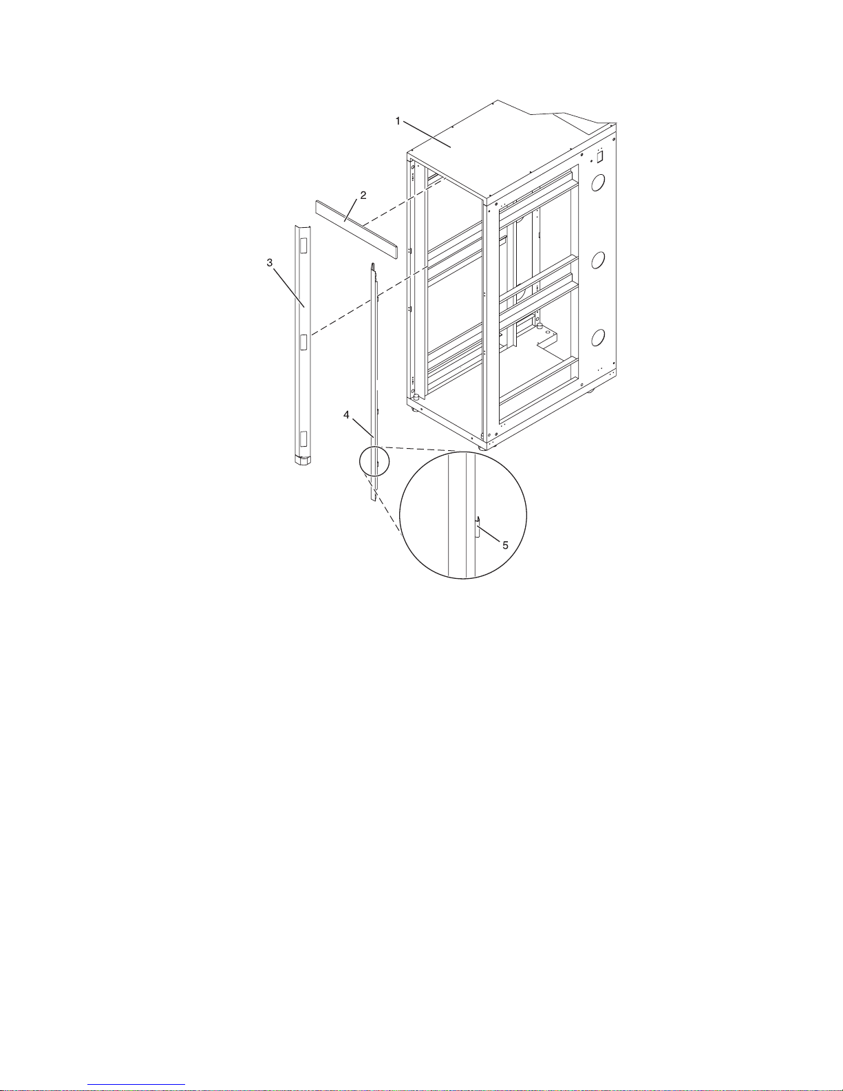
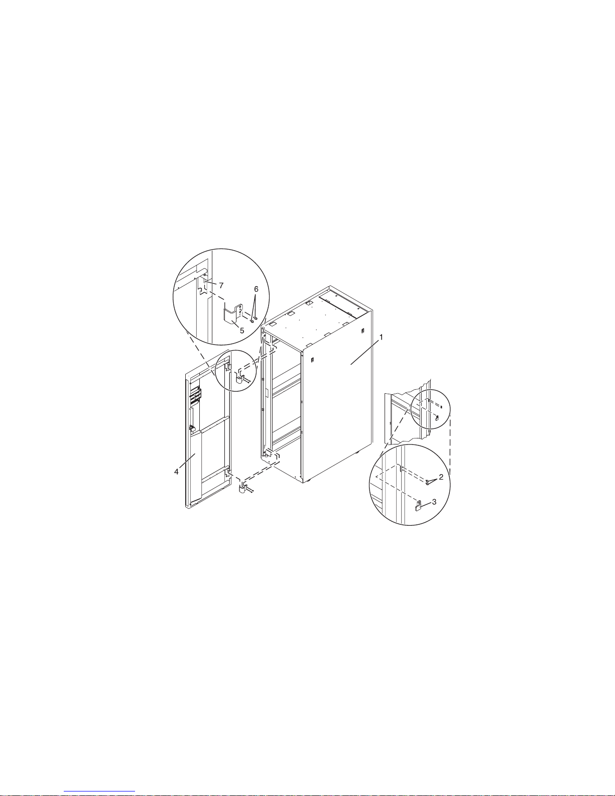
Installing the rack security kit
You might need to install the rack security kit. Use the procedure in this section to perform this task.
To install a rack security kit that consists of the security lock and security slide bars, complete the
following procedure:
1. Read the “Rack safety notices” on page 5.
2. Verify the inventory in the rack security kit.
v
27. Rack security kit inventory.
Figure
1 Two lock hardware kits. Each kit contains:
- Rack lock
- Bracket
- Screw
- Tw o keys
2 Two security slide bars
3 Two locked/unlocked stickers
Chapter 2. Installing your system in a rack 35

3. Remove the existing door latch.
Figure 28. Removing the existing door latch.
a. Open the front rack door.
b. On the inside of the door, remove the screw 4 in Figure 28, that secures the lock to the rack door.
c. Remove the bracket 5.
d. From the outside of the door, remove the door latch 6.
If the rack is equipped with the ruggedized kit, remove the jam nut and hex nut from the
Note:
existing door latch and reinstall both nuts on the new door lock latch.
4. Install the locking latch.
a. Insert the keyed rack lock into the latch slot on the front of the door 6 in Figure 28.
b. Secure the lock by attaching the lock bracket 5 with the screw 4, on the inside of the door.
5. Repeat steps 3 and 4 to install the second lock on the back rack door.
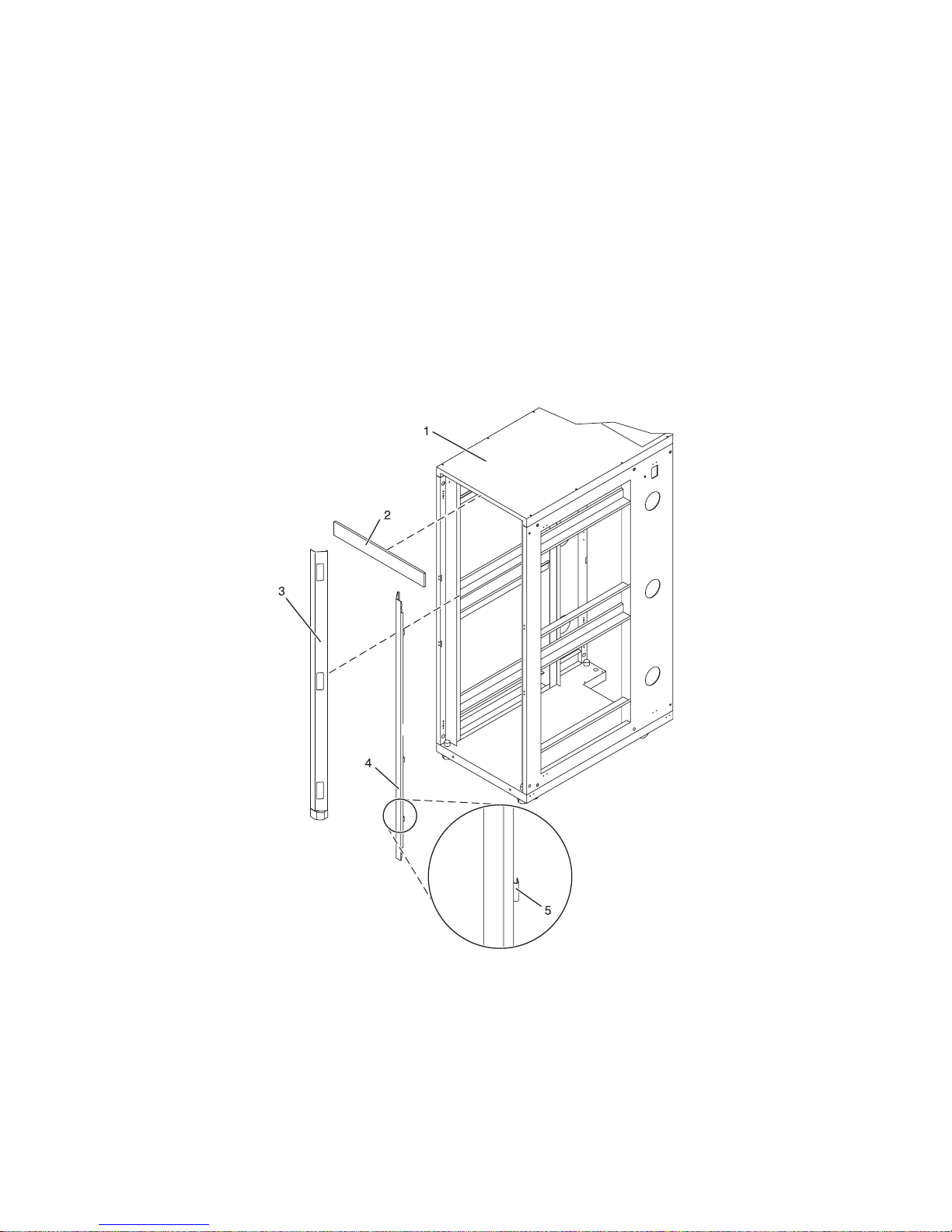
6. Install a security slide bar on the right side of the rack.
36 Installation Guide for the 03E/4A, 07M/15, and 08M/25

Figure 29. Installing a security slide bar.
Note: Each slide bar rail has two long tabs on the bottom of the rail. The slide bar rails are identical
and can be installed on either the right or left side cover panel.
a. Unlatch right-side cover panel and lean the panel back so that you can access the top of the panel.
b. With the flat side of the slide bar rail 7 in Figure 29, facing the inside of the cover panel 8, insert
the two tabs 9, on the slide bar rail into the two vertical support channels 10 on the side cover
panel.
Note: When installed correctly, the slide rail moves from front to back.
c. Reinstall the side panel cover on to the rack.
d. Lock the side panel covers by sliding the bars to the front of the rack.
e. Place a locked/unlocked sticker on the inside of the cover panel so that when the slide bar is in
the locked position, the tab is over the locked symbol, 11, as shown in Figure 30 on page 38 and
over the unlocked symbol, 12, when the slide bar is unlocked.
Chapter 2. Installing your system in a rack 37

Figure 30. Placing the locked/unlocked sticker on the cover panel.
f. Repeat the procedure for the left side of the rack.
Installing the model in a rack
You might need to install the system into a rack. Use the procedure in this section to perform this task.
This topic describes how to install the system in a rack. This is a customer task. You can perform this task
yourself, or contact a service provider to perform the task for you. You might be charged a fee by the
service provider for this service.
Important: To complete this procedure, use two people to attach the rail assembly to the rack, one in
front of the rack and one at the back of the rack. You will need three people to lift the system unit onto
the rack.
This procedure assumes that you are installing the system into an existing rack. If the rack is not
installed, go to the instructions for installing the rack and then return to this procedure for instructions
on installing the system unit in a rack.
Note: This procedure applies only to the models that are designed to be mounted in a rack. Do not
attempt to install a stand-alone model in a rack.
To install model in a rack, complete the following steps:
CAUTION:
Installing the rails in the rack is a complex procedure. To install the rails correctly, you must perform
each task in the following order. Failure to do so might cause rail failure and potential danger to
yourself and the system unit.
1. Read the “Rack safety notices” on page 5.
2. Complete a parts inventory, if you have not done so.
38 Installation Guide for the 03E/4A, 07M/15, and 08M/25

Figure 31. Rack-mounting kit
A Rack-mounting hardware kit
- Four large retaining screws
- Two rack-latch brackets
- Two rack-latch bracket screws
- Two cable restraint brackets
B Left and right rack rails with rack brackets
C Cable-management arm pins
D Cable-management arm bracket
E Cable-management arm
F Two rack latches
If there are incorrect, missing, or damaged parts, contact:
v Your reseller
Locate the rack-mounting hardware kit A, and the rack rails B that were included with your system
3.
unit as shown in Figure 31.
The system rails B are front-to-back and left-to-right side dependent. The rails are labeled left and
right to indicate their placement when you face the front of the rack. There are two large latch
assemblies at the back of each rail. These latch assemblies go in the back of the rack.
4. Determine where you will locate the system unit in the rack. See “Determining the location” on page
7.
Chapter 2. Installing your system in a rack 39

Attaching the mounting hardware to the rack
You might need to attach the mounting hardware to the rack. Use the procedure in this section to
perform this task.
Attention: Installing the rails in the rack is a complex procedure. To install the rails correctly, you must
perform each task in the following order. Failure to do so might cause rail failure and potential danger to
yourself and the system unit.
To install the rack-mounting hardware into the rack, complete the following steps:
1. With the right rail, pull back the latch assembly release tab, A in Figure 32, and then slide tab B back
to the retracted position and lock the latch assembly. The back-alignment pins should be fully
retracted.
2. After the alignment pins are retracted, insert the right side rail’s front-alignment pin as shown in
Figure 32, into the rack front flange hole identified by the self-adhesive placement dot that you
previously installed. Have a second person hold the rail securely in the front hole.
Figure 32. Front slide rail alignment pin, retaining screws, and latch bracket.
3. Align the back-alignment pins of the rail with the holes at the back of the rack identified by the
self-adhesive placement dots on the back of the rack. The back EIA location will be one position
higher than the front rail position. Ensure that the rails are level.
4. Slide the release tab, B, to extend the two back-alignment pins into the back of the rack. Ensure that
the pins have passed through the correct holes in the rack frame.
5. From the back of the rack, insert one of the large rail-retaining screws into the hole that is located
between the two back alignment pins. Partially tighten the screw. Do not tighten completely at this
time.
6. Repeat steps 1 through 5 for the left side rail.
40 Installation Guide for the 03E/4A, 07M/15, and 08M/25

7. Locate the two latch brackets, F in Figure 31 on page 39. Screw the brackets onto the sides of the
system (located near the front) using the two small screws.
8. Extend the inner rails by pulling the rails out. They should be extended from the frame as the rails
shown in Figure 33.
9. Using three people, grasp the two handles located on each side of the system drawer and place the
system onto the inner rail as shown in Figure 33.
Figure 33. Place system onto the rails
10. After the system is firmly in place, simultaneously press the safety latches and push the system unit
into the rack as shown in Figure 34 on page 42.
Chapter 2. Installing your system in a rack 41

Figure 34. Inner rail extended
11. Use the retaining screws to attach the rack latches to the rack as shown in Figure 35.
Figure 35. Secure system to rack through rack latches
42 Installation Guide for the 03E/4A, 07M/15, and 08M/25

12. After both rails have been installed, ensure that none of the rail’s retaining screws are more than
finger-tight. The rails must be level from front to back and from left to right.
Installing the cable-management arm
You might need to install the cable-management arm. Use the procedure in this section to perform this
task.
To install the cable-management arm, complete the following steps:
1. Determine on which side of the rack you want to install the cable-management arm.
2. Place the correct arm bracket (Left or Right) with the cable-management arm.
3. Use pin F to pin the cable-management arm E to the rack frame D as shown in Figure 36.
Figure 36. Attaching the cable-management arm.
Tip: If access to the back of the rack is obscured by a large number of existing cables, it might be
easier to remove the small connecting hinge from the cable-management arm and attach it first. Then,
you can attach the remaining section of the cable-management arm to the connecting hinge.
4. Use the second pin F to pin the other end of the cable-management arm to the flange C that is
attached to the sliding portion of the left system rail assembly B as shown in Figure 36.
Chapter 2. Installing your system in a rack 43

44 Installation Guide for the 03E/4A, 07M/15, and 08M/25

Chapter 3. Installing an 03E/4A with logical partitions
Use these tasks to set up your logical partitioned system.
Checklist: Installing an 03E/4A with logical partitions
The 03E/4A with logical partitions installation checklist comprises a complete, chronological list of all the
tasks associated with setting up your system. This is a comprehensive checklist. Complete only the tasks
that apply to your particular situation.
System installation tasks
__ Chapter 1, “Prerequisite tasks for the 03E/4A installation,” on page 3
__ Chapter 2, “Installing your system in a rack,” on page 5
__ “Cabling your server”
__ “Cabling the server and the Hardware Management Console (HMC)” on page 46
__ “Cabling the server to access the Integrated Virtualization Manager” on page 49
__ “Cabling the server to access the Operations Console” on page 53
__ “Setting up your console or interface and create logical partitions” on page 58
__ “Setting up the HMC and create logical partitions” on page 58
__ “Setting up Virtual I/O Server, IVM, and logical partitions” on page 59
__ “Setting up the Operations Console, twinaxial console, or 5250 console and creating logical partitions” on
page 59
__ “Installing operating systems” on page 60
__ “Installing AIX” on page 77
__ “Installing ” on page 77
__ “Installing Linux” on page 77
__ “Setting up your server to connect to service and support” on page 60
__ “Obtaining updates and upgrades” on page 60
__ “Obtaining HMC machine code updates and upgrades” on page 79
__ “Obtaining firmware updates” on page 79
__ “Obtaining operating system fixes” on page 82
Cabling your server
Learn how to cable your server with a console or interface that is available for your server. This might
include the Advanced System Management Interface (ASMI), Hardware Management Console (HMC), or
Integrated Virtualization Manager.
To learn more about the cabling options that are available for your server, see the following console and
interface descriptions.
Advanced System Management Interface
The Advanced System Management Interface (ASMI) is the interface to the service processor that
allows you to perform general and administrator-level service tasks, such as reading service
processor error logs, reading vital product data, setting up the service processor, and controlling
the system power. The ASMI might also be referred to as the service processor menus. Set up
access to the ASMI if you plan to manage the AIX® or Linux® operating systems without an
HMC. The ASMI can also be used to setup your Virtual I/O Server (VIOS).
Hardware Management Console
The Hardware Management Console (HMC) is a dedicated workstation that runs integrated
system management software. The HMC manages hardware tasks and configures logical
partitions on managed systems. It also acts as a focal point for hardware detection and reporting.
45

Integrated Virtualization Manager
The Integrated Virtualization Manager provides a Web-based system management interface and a
command-line interface that you can use to manage and configure servers that use the Virtual
I/O Server. On the managed system, you can create logical partitions, manage the virtual storage
and virtual Ethernet, and view service information related to the server. The Integrated
Virtualization Manager is packaged with the Virtual I/O Server, but it is enabled only on certain
platforms and where no Hardware Management Console (HMC) is present.
Cabling the server and the Hardware Management Console (HMC)
Learn how to cable the expansion units, connect the external cables, power cords, and HMC cables, attach
devices, and route the cables after you install all of your hardware features or replace parts.
DANGER
working on or around the system, observe the following precautions:
When
Electrical voltage and current from power, telephone, and communication cables are hazardous. To
avoid a shock hazard:
v Connect power to this unit only with the provided power cord. Do not use the provided power
cord for any other product.
v Do not open or service any power supply assembly.
v Do not connect or disconnect any cables or perform installation, maintenance, or reconfiguration
of this product during an electrical storm.
v The product might be equipped with multiple power cords. To remove all hazardous voltages,
disconnect all power cords.
v Connect all power cords to a properly wired and grounded electrical outlet. Ensure that the outlet
supplies proper voltage and phase rotation according to the system rating plate.
v Connect any equipment that will be attached to this product to properly wired outlets.
v When possible, use one hand only to connect or disconnect signal cables.
v Never turn on any equipment when there is evidence of fire, water, or structural damage.
v Disconnect the attached power cords, telecommunications systems, networks, and modems before
you open the device covers, unless instructed otherwise in the installation and configuration
procedures.
v Connect and disconnect cables as described in the following procedures when installing, moving,
or opening covers on this product or attached devices.
To Disconnect:
1. Turn off everything (unless instructed otherwise).
2. Remove the power cords from the outlets.
3. Remove the signal cables from the connectors.
4. Remove all cables from the devices
To Connect:
1. Turn off everything (unless instructed otherwise).
2. Attach all cables to the devices.
3. Attach the signal cables to the connectors.
4. Attach the power cords to the outlets.
5. Turn on the devices.
(D005a)
To cable your server:
Before you begin
__ If you have hardware features that are not installed, install them now. For instructions, see the corresponding
feature book at PDF files.
46 Installation Guide for the 03E/4A, 07M/15, and 08M/25

Cabling the expansion units
__ Do you have an expansion unit?
v Yes. To view the PDF file of Enclosures and Expansion Units (SA76-0151), approximately 9 MB in size, see
sa76-0151.pdf
. See Chapter 2 ″Connect your Expansion units ″ for instructions on the following tasks:
– Setting up an expansion unit
– Creating a new RIO/HSL or SPCN loop
– Adding a system or expansion unit into an existing RIO/HSL or SPCN loop
Do not plug the expansion-unit power cord into the power outlet, as directed by the instructions in
Note:
Expansion units, until later in this checklist.
v No. Proceed to the next section, Connecting the external cables.
Connecting the external cables
__ If you are using any optional adapters (such as token ring or 8-port EIA-232), connect the cables to the
appropriate adapter connectors in the PCI slots of your machine.
Note: If the cable was not provided with your server, you will have to supply it.
Attaching devices by using a system port
__
Connecting the power cords
__ To prevent the power cords from becoming unplugged unexpectedly, route the power cords through the
retention brackets that are provided .
__ If your server is equipped with a retention bracket, route the power cord under the bracket before you
plug it into the back of the server, as shown here:
Figure 37. Plug power cord into system
Chapter 3. Installing an 03E/4A with logical partitions 47

Connecting the power cords
__ Plug the power cords into the system, display, and attached devices. Do not connect the power cords to a
power source until instructed to do so.
Note: If you connect your server to a power source before the HMC is configured as the DHCP server, the
server will initialize by using the default IP address values (HMC1 as 169.254.2.147 and HMC2 as 169.254.3.147)
instead of waiting for an address value from the HMC. If you inadvertently connect your server to a power
source, the IP address value will be corrected in the HMC configuration portion of the installation.
Connecting the HMC cables
__ Cable the HMC. To view the PDF file of the Installation and Configuration Guide for the Hardware Management
Console (SA76-0084), approximately 3 MB in size, see sa76-0084.pdf
. See Chapter 5 Setting up the HMC –>
Cabling your stand-alone HMC for instructions and then return to this step.
Routing the cables through the cable-management arm
__ Is your server installed in a rack?
v No. Proceed to the next section, After you finish.
v Yes. Do the following:
__ Place the rack-mounted system in the service position. For instructions, see “Place the rack-mounted model
04E/8A, 03E/4A in the service position” on page 82.
__ Route the cables through the hooks that are located along the cable-management arm and secure them with
the straps that are provided, as shown here:
__ After attaching the cables to the cable-management arm, go to the front of the rack and move the system
drawer in and out. Observe the cables and cable-management-arm movement to verify that the cables are
not binding.
48 Installation Guide for the 03E/4A, 07M/15, and 08M/25

After you finish
__ Did you receive a cable hook with your rack shipment?
v No. Continue to the next task.
v Yes. The cable hook manages the server cables in the back of the rack. To install the cable hook, slide it into
the slots that are located on the back of the rack as shown here:
Cabling the server to access the Integrated Virtualization Manager
Learn how to access the Integrated Virtualization Manager, connect external cables and power cords,
route the cables, and attach devices after you install all of your hardware features or replace parts.
Chapter 3. Installing an 03E/4A with logical partitions 49

DANGER
working on or around the system, observe the following precautions:
When
Electrical voltage and current from power, telephone, and communication cables are hazardous. To
avoid a shock hazard:
v Connect power to this unit only with the provided power cord. Do not use the provided power
cord for any other product.
v Do not open or service any power supply assembly.
v Do not connect or disconnect any cables or perform installation, maintenance, or reconfiguration
of this product during an electrical storm.
v The product might be equipped with multiple power cords. To remove all hazardous voltages,
disconnect all power cords.
v Connect all power cords to a properly wired and grounded electrical outlet. Ensure that the outlet
supplies proper voltage and phase rotation according to the system rating plate.
v Connect any equipment that will be attached to this product to properly wired outlets.
v When possible, use one hand only to connect or disconnect signal cables.
v Never turn on any equipment when there is evidence of fire, water, or structural damage.
v Disconnect the attached power cords, telecommunications systems, networks, and modems before
you open the device covers, unless instructed otherwise in the installation and configuration
procedures.
v Connect and disconnect cables as described in the following procedures when installing, moving,
or opening covers on this product or attached devices.
To Disconnect:
1. Turn off everything (unless instructed otherwise).
2. Remove the power cords from the outlets.
3. Remove the signal cables from the connectors.
4. Remove all cables from the devices
To Connect:
1. Turn off everything (unless instructed otherwise).
2. Attach all cables to the devices.
3. Attach the signal cables to the connectors.
4. Attach the power cords to the outlets.
5. Turn on the devices.
(D005a)
To cable your server:
Before you begin
__ If you have hardware features that are not installed, install them now. For instructions, see the corresponding
feature book at PDF files.
Connecting the serial cable
__ Connect one end of a null modem cable to a system port on the back of your server, and the other end to a
serial port on a PC that has Microsoft® Internet Explorer 6.0, Netscape 7.1, or Opera 7.23 installed.
50 Installation Guide for the 03E/4A, 07M/15, and 08M/25

Cabling the expansion units
__ Do you have an expansion unit?
v Yes. To view the PDF file of Enclosures and Expansion Units (SA76-0151), approximately 9 MB in size, see
sa76-0151.pdf
. See Chapter 2 ″Connect your Expansion units ″ for instructions on the following tasks:
– Setting up an expansion unit
– Creating a new RIO/HSL or SPCN loop
– Adding a system or expansion unit into an existing RIO/HSL or SPCN loop
Do not plug the expansion-unit power cord into the power outlet, as directed by the instructions in
Note:
Expansion units, until later in this checklist.
v No. Proceed to the next section, Connecting the external cables.
Connecting the external cables
__ If you are using any optional adapters (such as token ring or 8-port EIA-232), connect the cables to the
appropriate adapter connectors in the PCI slots of your machine.
Note: If the cable was not provided with your server, you will have to supply it.
Connecting the server’s power cord
__ To prevent the power cord from becoming unplugged unexpectedly, route the server’s power cord through the
retention bracket that is provided.
__ If your server is equipped with a retention bracket, route the power cord under the bracket before you
plug it into the back of the server as shown here:
Figure 38. Plug power cord into system
__ Plug the power cord into the system.
Attaching devices by using a system port
__ If you want to access the ASMI when the system is in standby, attach an ASCII terminal to a system port on the
back of the server.
Chapter 3. Installing an 03E/4A with logical partitions 51

Attaching devices by using a system port
__ If you want to access the ASMI remotely when the system is in standby, attach a modem to a system port on the
back of the server.
__ If you are connecting the device to an uninterruptible power supply, see the documentation that is included
with your uninterruptible power supply. You might need additional hardware.
Note: For the model 5/10, 5/1A, 5/20, 5/2A, 5/50, 5/5A, 5/60, or 5/70 servers, any other application that uses a
system port requires a system port adapter to be installed into a PCI slot.
Connecting the power cords
__ Connect the power cords from the display and attached devices to a power source.
Accessing the Advanced System Management Interface (ASMI)
__ If you plan to connect a PC (with a browser) to the server to access the ASMI, see the Operations Guide for
ASMI and for Nonpartitioned Systems. To view the PDF file of the Operations Guide for ASMI and for
Nonpartitioned Systems (SA76-0094), approximately 2 MB in size, see sa76-0094.pdf
. See Chapter 2 -
Managing the Advanced System Management Interface (ASMI) –> Accessing the ASMI.
__ If you plan to use the ASCII terminal to access the ASMI, the Operations Guide for ASMI and for
Nonpartitioned Systems. To view the PDF file of the Operations Guide for ASMI and for Nonpartitioned Systems
(SA76-0094), approximately 2 MB in size, see sa76-0094.pdf
. See Chapter 2 - Managing the Advanced
System Management Interface (ASMI) –> Accessing the ASMI.
Routing the cables through the cable-management arm
__ Is your server installed in a rack?
v No. Proceed to the next section, After you finish.
v Yes. Do the following:
__ Place the rack-mounted system in the service position. For instructions, see “Place the rack-mounted model
04E/8A, 03E/4A in the service position” on page 82.
__ Route the cables through the hooks that are located along the cable-management arm and secure them with
the straps that are provided, as shown here:
__ After attaching the cables to the cable-management arm, go to the front of the rack and move the system
drawer in and out. Observe the cables and cable-management-arm movement to verify that the cables are
not binding.
52 Installation Guide for the 03E/4A, 07M/15, and 08M/25

After you finish
__ Did you receive a cable hook with your rack shipment?
v No. Proceed to the next item.
v Yes. The cable hook manages the server cables in the back of the rack. To install the cable hook, slide it into
the slots that are located on the back of the rack as shown here:
Cabling the server to access the Operations Console
This section explains how to access the Operations Console, connect external cables and power cords,
route the cables, and attach devices after you install all of your hardware features or replace parts.
Chapter 3. Installing an 03E/4A with logical partitions 53

DANGER
working on or around the system, observe the following precautions:
When
Electrical voltage and current from power, telephone, and communication cables are hazardous. To
avoid a shock hazard:
v Connect power to this unit only with the provided power cord. Do not use the provided power
cord for any other product.
v Do not open or service any power supply assembly.
v Do not connect or disconnect any cables or perform installation, maintenance, or reconfiguration
of this product during an electrical storm.
v The product might be equipped with multiple power cords. To remove all hazardous voltages,
disconnect all power cords.
v Connect all power cords to a properly wired and grounded electrical outlet. Ensure that the outlet
supplies proper voltage and phase rotation according to the system rating plate.
v Connect any equipment that will be attached to this product to properly wired outlets.
v When possible, use one hand only to connect or disconnect signal cables.
v Never turn on any equipment when there is evidence of fire, water, or structural damage.
v Disconnect the attached power cords, telecommunications systems, networks, and modems before
you open the device covers, unless instructed otherwise in the installation and configuration
procedures.
v Connect and disconnect cables as described in the following procedures when installing, moving,
or opening covers on this product or attached devices.
To Disconnect:
1. Turn off everything (unless instructed otherwise).
2. Remove the power cords from the outlets.
3. Remove the signal cables from the connectors.
4. Remove all cables from the devices
To Connect:
1. Turn off everything (unless instructed otherwise).
2. Attach all cables to the devices.
3. Attach the signal cables to the connectors.
4. Attach the power cords to the outlets.
5. Turn on the devices.
(D005a)
To cable your server:
Before you begin
__ Before you cable your server with Operations Console, determine the type of connection you will be making.
You can attach directly to the server using the Operations Console cable or connect on a network (LAN) using
an Ethernet cable.
__ If you have hardware features that are not installed, install them now. For instructions, see the corresponding
feature book at PDF files.
54 Installation Guide for the 03E/4A, 07M/15, and 08M/25

Connecting the console
__ Important: The server must be powered off. Do not power on the server until you are instructed to do so.
The following steps assume you have already set up the PCs that are connecting to the system. You can also use
these steps if you are removing one or more cables from your PC, server, or both.
Note: If you do not have your PC setup to connect to the system, setup your PC using the PC user manual.
To connect the Operations Console cable (97H7557 or 39J5835) directly attached:
1. Shut down and unplug the PC that will serve as the system console.
2. Locate the Operations Console cable (97H7557 or 39J5835), and connect the Operations Console cable to the
corresponding connector on the adapter of the managed system.
Note: If you are using the 2742 adapter, the Operations Console cable must be attached to the lower
connector.
3. On the back of the PC that is being used as the console, connect the other end of the Operations Console
cable to the first or only system port.
To
connect the Ethernet cable on a network (LAN):
1. Shut down and unplug the PC that will serve as the system console.
2. Connect the network cable from the PC that will serve as the system console to your local network.
3. Connect another network cable from the same local network to the adapter to be used for the console. It is
either located in a specific location or has been tagged using the HMC.
Notes:
v The 2849 adapter requires an input/output processor (IOP) that must be located in an expansion unit.
v If you are using the 5706/5707 or 5767/5768 adapter, you must connect the network cable to port 1 (top
connector).
Cabling the expansion units
__ Do you have an expansion unit?
v Yes. To view the PDF file of Enclosures and Expansion Units (SA76-0151), approximately 9 MB in size, see
sa76-0151.pdf
. See Chapter 2 ″Connect your Expansion units ″ for instructions on the following tasks:
– Setting up an expansion unit
– Creating a new RIO/HSL or SPCN loop
– Adding a system or expansion unit into an existing RIO/HSL or SPCN loop
Do not plug the expansion-unit power cord into the power outlet, as directed by the instructions in
Note:
Expansion units, until later in this checklist.
v No. Proceed to the next section, Connecting the external cables.
Connecting the server’s power cord
__ To prevent the power cord from becoming unplugged unexpectedly, route the server’s power cord through the
retention bracket that is provided.
Chapter 3. Installing an 03E/4A with logical partitions 55

Connecting the server’s power cord
__ If your server is equipped with a retention bracket, route the power cord under the bracket before you
plug it into the back of the server as shown here:
Figure 39. Plug power cord into system
__ Plug the power cord into the system.
Connecting the power cords
__ Connect the power cords from the display and attached devices to a power source.
Routing the cables through the cable-management arm
__ Is your server installed in a rack?
v No. Proceed to the next section, After you finish.
v Yes. Do the following:
__ Place the rack-mounted system in the service position. For instructions, see “Place the rack-mounted model
04E/8A, 03E/4A in the service position” on page 82.
56 Installation Guide for the 03E/4A, 07M/15, and 08M/25

Routing the cables through the cable-management arm
__ Route the cables through the hooks that are located along the cable-management arm and secure them with
the straps that are provided, as shown here:
__ After attaching the cables to the cable-management arm, go to the front of the rack and move the system
drawer in and out. Observe the cables and cable-management-arm movement to verify that the cables are
not binding.
Chapter 3. Installing an 03E/4A with logical partitions 57

After you finish
__ Did you receive a cable hook with your rack shipment?
v No. Proceed to the next item.
v Yes. The cable hook manages the server cables in the back of the rack. To install the cable hook, slide it into
the slots that are located on the back of the rack as shown here:
Setting up your console or interface and create logical partitions
To manage your system with logical partitions, you can use either the Hardware Management Console
(HMC) or the Integrated Virtualization Manager (IVM).
Setting up the HMC and create logical partitions
Follow these tasks to set up your HMC and to create logical partitions for your system.
1. See the Installation and Configuration Guide for the Hardware Management Console. To view the
PDF file of the Installation and Configuration Guide for the Hardware Management Console (SA76-0084),
approximately 3 MB in size, see sa76-0084.pdf
Complete the steps listed within Chapter 5 ″Setting up the HMC″ and Chapter 6 ″Configuring the
HMC″ and return to this step.
2. Ensure that the power cables of the managed system are connected to the power source.
3. Power on your managed system. To power on a managed system:
Use the Power On task to start a managed system.
Choose from three different options to start your managed system:
.
58 Installation Guide for the 03E/4A, 07M/15, and 08M/25

v Partition standby: When the Partition standby power-on is completed, the system will be in
standby mode. Partition standby mode allows you to create and activate logical partitions.
v System profile: Powers on the system according to a predefined set of system profiles. Select the
system profile that you want to use from the list.
v Partition auto start: Powers on the managed system to partition standby mode and then activates
all partitions that are marked as auto start or those partitions that were running when the system
shut down. For example, if you create a partition with four processors, dynamically remove one
processor from the logical partition, and then shut down the system, the partition auto start option
activates this partition with three processors because the three-processor configuration was the last
configuration used. The Hardware Management Console (HMC) ignores whatever is specified in
the profile for the partition. Yo u can create and activate logical partitions in partition auto start
mode.
If you have AIX installed on this system, do the following:
Note:
a. Power using the Partition standby power on option. Do not use the Partition autostart option.
b. Select the partition from which to boot and activate.
c. Select the ″Exit MDC″ option.
4. See the Logical Partitioning Guide. To view the PDF file of the Logical Partitioning Guide (SA76-0098),
approximately 3 MB in size, see sa76-0098.pdf
.
Proceed to Chapter 4 ″Partitioning with the HMC″ –> ″Configuring logical partitions using the HMC.″
Complete the steps listed in the section ″Configuring logical partitions using the HMC″ and return to
this step.
Setting up Virtual I/O Server, IVM, and logical partitions
Follow these tasks to set up your VIOS, IVM, and to create logical partitions for your system.
Go to the PowerVM Editions Operations Guide. To view the PDF file of the PowerVM™ Editions Operations
Guide (SA76-0100), approximately 4 MB in size, see sa76-0100.pdf
.
Complete the steps listed within ″Virtual I/O Server″ and ″Integrated Virtualization Manager″. When
completed, return to this step.
Setting up the Operations Console, twinaxial console, or 5250 console
and creating logical partitions
Follow these tasks to set up your Operations Console, twinaxial console, or 5250 console and to create
logical partitions for your system.
Go to the Operations Guide for i5/OS Consoles. To view the PDF file of the Operations Guide for i5/OS
Consoles (SA76-0128), approximately 2 MB in size, see sa76-0128.pdf
.
Complete the steps listed within Chapters 1, 2, and 3 if setting up a Operations Console. If setting up a
twinaxial console, complete the steps in Chapter 6. If setting up a 5250 console, complete the steps in
Chapter 7. When completed, return to this step.
Note: If you are changing the console device, the server value QAUTOCFG must be set to ON. Use one of
the following options to verify or set this system value on the server:
v Use the WRKSYSVAL QAUTOCFG command.
v During a manual IPL in the IPL Options window, for Set major system options, select Y. Then for
Enable automatic configuration, select Y.
®
Chapter 3. Installing an 03E/4A with logical partitions 59

To set up your logical partitions, see the Logical Partitioning Guide. To view the PDF file of the Logical
Partitioning Guide (SA76-0098), approximately 3 MB in size, see sa76-0098.pdf
. Proceed to Chapter 4
″Partitioning with the HMC″ –> ″Configuring logical partitions using the HMC.″ Complete the steps
listed in the section ″Configuring logical partitions using the HMC″ and return to this step.
Setting up your server to connect to service and support
Learn about setting up your server to connect to service and support.
After you have configured your HMC (if you have one), you must set up the connection to service and
support from your server. This connection can provide two-way communication between your server and
service and support. Each operating environment has requirements to consider when you set up your
connections.
Installing operating systems
You can install the AIX or Linux operating systems.
To install an operating system, see one of the following sections. Complete the tasks in that section and
return to this step.
v “Installing AIX” on page 77
v “Installing Linux” on page 77
Obtaining updates and upgrades
Follow these steps to obtain updates and upgrades to your HMC machine code, firmware, and operating
systems.
To obtain updates and upgrades, complete the tasks in the following sections:
v “Obtaining HMC machine code updates and upgrades” on page 79
v “Obtaining firmware updates” on page 79
v “Obtaining operating system fixes” on page 82
60 Installation Guide for the 03E/4A, 07M/15, and 08M/25

Chapter 4. Installing a model 03E/4A without logical partitions
Use the tasks within this section to set up your system without logical partitions.
Checklist: Installing an 03E/4A without logical partitions
The 03E/4A without logical partitions installation checklist comprises a complete list of all the tasks for
setting up your system. This is a comprehensive checklist. Complete only the tasks that apply to your
particular situation.
System installation tasks
__ Chapter 1, “Prerequisite tasks for the 03E/4A installation,” on page 3
__ Chapter 2, “Installing your system in a rack,” on page 5
__ “Cabling your server”
__ “Cabling the server to access the Advanced System Management Interface (ASMI)” on page 65
__ “Cabling the server and the Hardware Management Console (HMC)” on page 62
__ “Cabling the server to access the Operations Console” on page 69
__ “Setting up your console, terminal, or interface to manage your system” on page 74
__ “Setting up the HMC” on page 74
__ “Connecting to ASMI or SMS menus” on page 75
__ “Setting up the Operations Console or 5250 console” on page 75
__ “Installing operating systems” on page 75
__ “Installing AIX” on page 77
__ “Installing ” on page 77
__ “Installing Linux” on page 77
__ “Setting up your server to connect to service and support” on page 75
__ “Obtaining updates and upgrades” on page 76
__ “Obtaining HMC machine code updates and upgrades” on page 79
__ “Obtaining firmware updates” on page 79
__ “Obtaining operating system fixes” on page 82
Cabling your server
Learn how to cable your server with a console or interface that is available for your server. This might
include the Advanced System Management Interface (ASMI), the Hardware Management Console (HMC,
or the Operations Console.
To learn more about the cabling options that are available for your server, see the following console and
interface descriptions.
Advanced System Management Interface
The Advanced System Management Interface (ASMI) is the interface to the service processor that
allows you to perform general and administrator-level service tasks, such as reading service
processor error logs, reading vital product data, setting up the service processor, and controlling
the system power. The ASMI might also be referred to as the service processor menus. Set up
access to the ASMI if you plan to manage the AIX or Linux operating systems without an HMC.
The ASMI can also be used to setup your Virtual I/O Server (VIOS).
Hardware Management Console
The Hardware Management Console (HMC) is a dedicated workstation that runs integrated
system management software. The HMC manages hardware tasks and configures logical
partitions on managed systems. It also acts as a focal point for hardware detection and reporting.
61

Cabling the server and the Hardware Management Console (HMC)
Learn how to cable the expansion units, connect the external cables, power cords, and HMC cables, attach
devices, and route the cables after you install all of your hardware features or replace parts.
DANGER
working on or around the system, observe the following precautions:
When
Electrical voltage and current from power, telephone, and communication cables are hazardous. To
avoid a shock hazard:
v Connect power to this unit only with the provided power cord. Do not use the provided power
cord for any other product.
v Do not open or service any power supply assembly.
v Do not connect or disconnect any cables or perform installation, maintenance, or reconfiguration
of this product during an electrical storm.
v The product might be equipped with multiple power cords. To remove all hazardous voltages,
disconnect all power cords.
v Connect all power cords to a properly wired and grounded electrical outlet. Ensure that the outlet
supplies proper voltage and phase rotation according to the system rating plate.
v Connect any equipment that will be attached to this product to properly wired outlets.
v When possible, use one hand only to connect or disconnect signal cables.
v Never turn on any equipment when there is evidence of fire, water, or structural damage.
v Disconnect the attached power cords, telecommunications systems, networks, and modems before
you open the device covers, unless instructed otherwise in the installation and configuration
procedures.
v Connect and disconnect cables as described in the following procedures when installing, moving,
or opening covers on this product or attached devices.
To Disconnect:
1. Turn off everything (unless instructed otherwise).
2. Remove the power cords from the outlets.
3. Remove the signal cables from the connectors.
4. Remove all cables from the devices
To Connect:
1. Turn off everything (unless instructed otherwise).
2. Attach all cables to the devices.
3. Attach the signal cables to the connectors.
4. Attach the power cords to the outlets.
5. Turn on the devices.
(D005a)
To cable your server:
Before you begin
__ If you have hardware features that are not installed, install them now. For instructions, see the corresponding
feature book at PDF files.
62 Installation Guide for the 03E/4A, 07M/15, and 08M/25

Cabling the expansion units
__ Do you have an expansion unit?
v Yes. To view the PDF file of Enclosures and Expansion Units (SA76-0151), approximately 9 MB in size, see
sa76-0151.pdf
. See Chapter 2 ″Connect your Expansion units ″ for instructions on the following tasks:
– Setting up an expansion unit
– Creating a new RIO/HSL or SPCN loop
– Adding a system or expansion unit into an existing RIO/HSL or SPCN loop
Do not plug the expansion-unit power cord into the power outlet, as directed by the instructions in
Note:
Expansion units, until later in this checklist.
v No. Proceed to the next section, Connecting the external cables.
Connecting the external cables
__ If you are using any optional adapters (such as token ring or 8-port EIA-232), connect the cables to the
appropriate adapter connectors in the PCI slots of your machine.
Note: If the cable was not provided with your server, you will have to supply it.
Attaching devices by using a system port
__
Connecting the power cords
__ To prevent the power cords from becoming unplugged unexpectedly, route the power cords through the
retention brackets that are provided .
__ If your server is equipped with a retention bracket, route the power cord under the bracket before you
plug it into the back of the server, as shown here:
Figure 40. Plug power cord into system
Chapter 4. Installing a model 03E/4A without logical partitions 63

Connecting the power cords
__ Plug the power cords into the system, display, and attached devices. Do not connect the power cords to a
power source until instructed to do so.
Note: If you connect your server to a power source before the HMC is configured as the DHCP server, the
server will initialize by using the default IP address values (HMC1 as 169.254.2.147 and HMC2 as 169.254.3.147)
instead of waiting for an address value from the HMC. If you inadvertently connect your server to a power
source, the IP address value will be corrected in the HMC configuration portion of the installation.
Connecting the HMC cables
__ Cable the HMC. To view the PDF file of the Installation and Configuration Guide for the Hardware Management
Console (SA76-0084), approximately 3 MB in size, see sa76-0084.pdf
. See Chapter 5 Setting up the HMC –>
Cabling your stand-alone HMC for instructions and then return to this step.
Routing the cables through the cable-management arm
__ Is your server installed in a rack?
v No. Proceed to the next section, After you finish.
v Yes. Do the following:
__ Place the rack-mounted system in the service position. For instructions, see “Place the rack-mounted model
04E/8A, 03E/4A in the service position” on page 82.
__ Route the cables through the hooks that are located along the cable-management arm and secure them with
the straps that are provided, as shown here:
__ After attaching the cables to the cable-management arm, go to the front of the rack and move the system
drawer in and out. Observe the cables and cable-management-arm movement to verify that the cables are
not binding.
64 Installation Guide for the 03E/4A, 07M/15, and 08M/25

After you finish
__ Did you receive a cable hook with your rack shipment?
v No. Continue to the next task.
v Yes. The cable hook manages the server cables in the back of the rack. To install the cable hook, slide it into
the slots that are located on the back of the rack as shown here:
Cabling the server to access the Advanced System Management
Interface (ASMI)
Learn how to access the ASMI, connect external cables and power cords, cable the expansion units, attach
devices, route the cables, and start your server after you install all of your hardware features or replace
parts.
Chapter 4. Installing a model 03E/4A without logical partitions 65

DANGER
working on or around the system, observe the following precautions:
When
Electrical voltage and current from power, telephone, and communication cables are hazardous. To
avoid a shock hazard:
v Connect power to this unit only with the provided power cord. Do not use the provided power
cord for any other product.
v Do not open or service any power supply assembly.
v Do not connect or disconnect any cables or perform installation, maintenance, or reconfiguration
of this product during an electrical storm.
v The product might be equipped with multiple power cords. To remove all hazardous voltages,
disconnect all power cords.
v Connect all power cords to a properly wired and grounded electrical outlet. Ensure that the outlet
supplies proper voltage and phase rotation according to the system rating plate.
v Connect any equipment that will be attached to this product to properly wired outlets.
v When possible, use one hand only to connect or disconnect signal cables.
v Never turn on any equipment when there is evidence of fire, water, or structural damage.
v Disconnect the attached power cords, telecommunications systems, networks, and modems before
you open the device covers, unless instructed otherwise in the installation and configuration
procedures.
v Connect and disconnect cables as described in the following procedures when installing, moving,
or opening covers on this product or attached devices.
To Disconnect:
1. Turn off everything (unless instructed otherwise).
2. Remove the power cords from the outlets.
3. Remove the signal cables from the connectors.
4. Remove all cables from the devices
To Connect:
1. Turn off everything (unless instructed otherwise).
2. Attach all cables to the devices.
3. Attach the signal cables to the connectors.
4. Attach the power cords to the outlets.
5. Turn on the devices.
(D005a)
To cable your server:
Before you begin
__ If you have hardware features that are not installed, install them now. For instructions, see the corresponding
feature book at PDF files.
Cabling the expansion units
__ Do you have an expansion unit?
v Yes. To view the PDF file of Enclosures and Expansion Units (SA76-0151), approximately 9 MB in size, see
sa76-0151.pdf
. See Chapter 2 ″Connect your Expansion units ″ for instructions on the following tasks:
– Setting up an expansion unit
– Creating a new RIO/HSL or SPCN loop
– Adding a system or expansion unit into an existing RIO/HSL or SPCN loop
Do not plug the expansion-unit power cord into the power outlet, as directed by the instructions in
Note:
Expansion units, until later in this checklist.
v No. Proceed to the next section, Connecting the external cables.
66 Installation Guide for the 03E/4A, 07M/15, and 08M/25

Attaching devices by using a system port
__ If you are connecting it to an uninterruptible power supply, see the documentation that is included with your
uninterruptible power supply. You might need additional hardware.
Note: For the model 5/10, 5/1A, 5/20, 5/2A, 5/50, 5/5A, 5/60, or 5/70 servers, any other application that uses a
system port requires a system port adapter to be installed into a PCI slot.
Connecting the power cords
__ You should route the power cords through the retention brackets that are provided to prevent the power cords
from becoming unplugged unexpectedly.
__ If your server is equipped with a retention bracket, route the power cord under the bracket before you
plug it into the back of the server as shown here:
__ Plug the power cords into the system, display, and attached devices.
Accessing the Advanced System Management Interface (ASMI)
__ To setup and access the ASMI (including terminals), see “Connecting to ASMI or SMS menus” on page 75.
Routing the cables through the cable-management arm
__ Is your server installed in a rack?
v No. Proceed to the next section, Starting your server.
v Yes. Do the following:
__ Place the rack-mounted system in the service position. For instructions, see “Place the rack-mounted model
04E/8A, 03E/4A in the service position” on page 82.
Chapter 4. Installing a model 03E/4A without logical partitions 67

Routing the cables through the cable-management arm
__ Route the cables through the hooks that are located along the cable-management arm and secure them with
the straps that are provided, as shown here:
__ After attaching the cables to the cable-management arm, go to the front of the rack and move the system
drawer in and out. Observe the cables and cable-management-arm movement to verify that the cables are
not binding.
Starting your server
__ Power the system on.
Note: Expect a delay between the time that the power is applied to the server or workstation and the time that
an initial program load (IPL) can be performed. When power is initially applied to the server or workstation, the
service processor performs a self-check and leaves the control panel blank for up to two minutes. You must wait
until the C1XX XXXX progress codes are complete and the control panel displays 01 before you perform an IPL or
change the control panel functions. Once the green light is blinking, you can press the white button to power on.
68 Installation Guide for the 03E/4A, 07M/15, and 08M/25

After you finish
__ Did you receive a cable hook with your rack shipment?
v No. Proceed to the next item.
v Yes. The cable hook manages the server cables in the back of the rack. To install the cable hook, slide it into
the slots that are located on the back of the rack as shown here:
Cabling the server to access the Operations Console
This section explains how to access the Operations Console, connect external cables and power cords,
route the cables, and attach devices after you install all of your hardware features or replace parts.
Chapter 4. Installing a model 03E/4A without logical partitions 69

DANGER
working on or around the system, observe the following precautions:
When
Electrical voltage and current from power, telephone, and communication cables are hazardous. To
avoid a shock hazard:
v Connect power to this unit only with the provided power cord. Do not use the provided power
cord for any other product.
v Do not open or service any power supply assembly.
v Do not connect or disconnect any cables or perform installation, maintenance, or reconfiguration
of this product during an electrical storm.
v The product might be equipped with multiple power cords. To remove all hazardous voltages,
disconnect all power cords.
v Connect all power cords to a properly wired and grounded electrical outlet. Ensure that the outlet
supplies proper voltage and phase rotation according to the system rating plate.
v Connect any equipment that will be attached to this product to properly wired outlets.
v When possible, use one hand only to connect or disconnect signal cables.
v Never turn on any equipment when there is evidence of fire, water, or structural damage.
v Disconnect the attached power cords, telecommunications systems, networks, and modems before
you open the device covers, unless instructed otherwise in the installation and configuration
procedures.
v Connect and disconnect cables as described in the following procedures when installing, moving,
or opening covers on this product or attached devices.
To Disconnect:
1. Turn off everything (unless instructed otherwise).
2. Remove the power cords from the outlets.
3. Remove the signal cables from the connectors.
4. Remove all cables from the devices
To Connect:
1. Turn off everything (unless instructed otherwise).
2. Attach all cables to the devices.
3. Attach the signal cables to the connectors.
4. Attach the power cords to the outlets.
5. Turn on the devices.
(D005a)
To cable your server:
Before you begin
__ Before you cable your server with Operations Console, determine the type of connection you will be making.
You can attach directly to the server using the Operations Console cable or connect on a network (LAN) using
an Ethernet cable.
__ If you have hardware features that are not installed, install them now. For instructions, see the corresponding
feature book at PDF files.
70 Installation Guide for the 03E/4A, 07M/15, and 08M/25

Connecting the console
__ Important: The server must be powered off. Do not power on the server until you are instructed to do so.
The following steps assume you have already set up the PCs that are connecting to the system. You can also use
these steps if you are removing one or more cables from your PC, server, or both.
Note: If you do not have your PC setup to connect to the system, setup your PC using the PC user manual.
To connect the Operations Console cable (97H7557 or 39J5835) directly attached:
1. Shut down and unplug the PC that will serve as the system console.
2. Locate the Operations Console cable (97H7557 or 39J5835), and connect the Operations Console cable to the
corresponding connector on the adapter of the managed system.
Note: If you are using the 2742 adapter, the Operations Console cable must be attached to the lower
connector.
3. On the back of the PC that is being used as the console, connect the other end of the Operations Console
cable to the first or only system port.
To
connect the Ethernet cable on a network (LAN):
1. Shut down and unplug the PC that will serve as the system console.
2. Connect the network cable from the PC that will serve as the system console to your local network.
3. Connect another network cable from the same local network to the adapter to be used for the console. It is
either located in a specific location or has been tagged using the HMC.
Notes:
v The 2849 adapter requires an input/output processor (IOP) that must be located in an expansion unit.
v If you are using the 5706/5707 or 5767/5768 adapter, you must connect the network cable to port 1 (top
connector).
Cabling the expansion units
__ Do you have an expansion unit?
v Yes. To view the PDF file of Enclosures and Expansion Units (SA76-0151), approximately 9 MB in size, see
sa76-0151.pdf
. See Chapter 2 ″Connect your Expansion units ″ for instructions on the following tasks:
– Setting up an expansion unit
– Creating a new RIO/HSL or SPCN loop
– Adding a system or expansion unit into an existing RIO/HSL or SPCN loop
Do not plug the expansion-unit power cord into the power outlet, as directed by the instructions in
Note:
Expansion units, until later in this checklist.
v No. Proceed to the next section, Connecting the external cables.
Connecting the server’s power cord
__ To prevent the power cord from becoming unplugged unexpectedly, route the server’s power cord through the
retention bracket that is provided.
Chapter 4. Installing a model 03E/4A without logical partitions 71

Connecting the server’s power cord
__ If your server is equipped with a retention bracket, route the power cord under the bracket before you
plug it into the back of the server as shown here:
Figure 41. Plug power cord into system
__ Plug the power cord into the system.
Connecting the power cords
__ Connect the power cords from the display and attached devices to a power source.
Routing the cables through the cable-management arm
__ Is your server installed in a rack?
v No. Proceed to the next section, After you finish.
v Yes. Do the following:
__ Place the rack-mounted system in the service position. For instructions, see “Place the rack-mounted model
04E/8A, 03E/4A in the service position” on page 82.
72 Installation Guide for the 03E/4A, 07M/15, and 08M/25

Routing the cables through the cable-management arm
__ Route the cables through the hooks that are located along the cable-management arm and secure them with
the straps that are provided, as shown here:
__ After attaching the cables to the cable-management arm, go to the front of the rack and move the system
drawer in and out. Observe the cables and cable-management-arm movement to verify that the cables are
not binding.
Chapter 4. Installing a model 03E/4A without logical partitions 73

After you finish
__ Did you receive a cable hook with your rack shipment?
v No. Proceed to the next item.
v Yes. The cable hook manages the server cables in the back of the rack. To install the cable hook, slide it into
the slots that are located on the back of the rack as shown here:
Setting up your console, terminal, or interface to manage your system
To manage your system without logical partitions, you can use either the HMC, the Advanced System
Management Interface (ASMI), or systems management services (SMS) menus. The ASMI can be accessed
through an ASCII terminal. SMS menus can be accessed through an ASCII or graphics terminal.
Setting up the HMC
Follow these tasks to set up your HMC for your system without logical partitions.
After setting up and configuring the HMC, complete the following steps:
1. Ensure that the power cables of the managed system are connected to the power source.
2. Power on your managed system. To power on a managed system:
Use the Power On task to start a managed system.
Choose from three different options to start your managed system:
v Partition standby: When the Partition standby power-on is completed, the system will be in
standby mode. Partition standby mode allows you to create and activate logical partitions.
v System profile: Powers on the system according to a predefined set of system profiles. Select the
system profile that you want to use from the list.
74 Installation Guide for the 03E/4A, 07M/15, and 08M/25

v Partition auto start: Powers on the managed system to partition standby mode and then activates
all partitions that are marked as auto start or those partitions that were running when the system
shut down. For example, if you create a partition with four processors, dynamically remove one
processor from the logical partition, and then shut down the system, the partition auto start option
activates this partition with three processors because the three-processor configuration was the last
configuration used. The Hardware Management Console (HMC) ignores whatever is specified in
the profile for the partition. Yo u can create and activate logical partitions in partition auto start
mode.
If you have AIX installed on this system, do the following:
Note:
a. Power using the Partition standby power on option. Do not use the Partition autostart option.
b. Select the partition from which to boot and activate.
c. Select the ″Exit MDC″ option.
Connecting to ASMI or SMS menus
Follow these tasks to connect to ASMI or SMS menus.
In order to connect and use the ASMI or SMS menus, you need to connect an ASCII or graphics terminal
to your server. To setup and connect those terminals, complete the tasks listed within Chapter 1 ″Getting
Started″ –> ″Connecting to a terminal″ in the Operations Guide for ASMI and for Nonpartitioned
Systems. To view the PDF file of the Operations Guide for ASMI and for Nonpartitioned Systems (SA76-0094),
approximately 2 MB in size, see sa76-0094.pdf
.
Setting up the Operations Console or 5250 console
Follow these tasks to set up your Operations Console or 5250 console.
Go to the Operations Guide for i5/OS Consoles. To view the PDF file of the Operations Guide for i5/OS
Consoles (SA76-0128), approximately 2 MB in size, see sa76-0128.pdf
.
Complete the steps listed within Chapters 1, 2, and 3 if setting up a Operations Console. If setting up a
twinaxial console, complete the steps in Chapter 6. If setting up a 5250 console, complete the steps in
Chapter 7. When completed, return to this step.
Note: If you are changing the console device, the server value QAUTOCFG must be set to ON. Use one of
the following options to verify or set this system value on the server:
v Use the WRKSYSVAL QAUTOCFG command.
v During a manual IPL in the IPL Options window, for Set major system options, select Y. Then for
Enable automatic configuration, select Y.
Setting up your server to connect to service and support
Learn about setting up your server to connect to service and support.
After you have configured your HMC (if you have one), you must set up the connection to service and
support from your server. This connection can provide two-way communication between your server and
service and support. Each operating environment has requirements to consider when you set up your
connections.
Installing operating systems
You can install the AIX or Linux operating systems.
Chapter 4. Installing a model 03E/4A without logical partitions 75

To install an operating system, see one of the following sections. Complete the tasks in that section and
return to this step.
v “Installing AIX” on page 77
v “Installing Linux” on page 77
Obtaining updates and upgrades
Follow these steps to obtain updates and upgrades to your HMC machine code, firmware, and operating
systems.
To obtain updates and upgrades, complete the tasks in the following sections:
v “Obtaining HMC machine code updates and upgrades” on page 79
v “Obtaining firmware updates” on page 79
v “Obtaining operating system fixes” on page 82
76 Installation Guide for the 03E/4A, 07M/15, and 08M/25

Chapter 5. Common procedures (installing operating systems
and obtaining updates) for the model 03E/4A
This topic contains two sections that are common to both a logical partitioned 03E/4A and a 03E/4A
without logical partitions.
After completing a section, return to your previous location depending on whether you are completing
the tasks in Chapter 3, “Installing an 03E/4A with logical partitions,” on page 45 or Chapter 4, “Installing
a model 03E/4A without logical partitions,” on page 61.
Installing AIX
AIX is one of the operating systems that can be installed on your server or logical partition.
The following topics are included with the AIX Information Center.
Installing
IBM® is one of the operating systems that can be installed on your server or logical partition.
Installing (http://publib.boulder.ibm.com/infocenter/systems/scope/i5os/topic/rzahc/rzahc1.htm)
Use this information to install or upgrade the operating system and related software in IBM
models. You can also use this information to delete unwanted licensed programs or parts of
licensed programs related to , to change a primary language, or to install a secondary language.
Installing Linux
A Linux distribution is one of the operating systems that can be installed on your server or logical
partition.
The following information includes instructions for preparation and installation of the Linux operating
system on your server, how to find documentation for Linux distributions, how to install software to
enable dynamic logical partitioning and other capabilities of your system, a detailed installation scenario,
and links to other related information.
Configuring Electronic Service Agent on standalone AIX systems
Follow these instructions to set up Electronic Service Agent on your AIX standalone system.
AIX version 5.3 Technology Level 6, and later, has the Electronic Service Agent 6.1 and later code in the
base operating system, as part of the base AIX installation media.
For Hardware Management Console controlled environments, Electronic Service Agent must be activated
on the HMC to report hardware errors and hardware service information for the entire system
environment. For installation instructions for the HMC, proceed to the Installation and Configuration
Guide for the Hardware Management Console. To view the PDF file of the Installation and Configuration
Guide for the Hardware Management Console (SA76-0084), approximately 3 MB in size, see sa76-0084.pdf
. Additional activation of Electronic Service Agent on each partition will report software service
information.
77

For non-HMC controlled systems, activating Electronic Service Agent on the AIX system will report
hardware errors along with hardware and software service information. Follow these instructions to set
up Electronic Service Agent on your AIX standalone system/partition.
1. Access the main menu on Electronic Service Agent:
a. Log in to the system as root, or sign on using a root-authorized ID.
b. Enter smit at the AIX command prompt.
c. Type smit esa_main.
d. If you are connecting to IBM Support through a direct internet connection, proceed to 3.
2. Configure connectivity by performing the following steps:
a. Select Configure Service Connectivity.
b. Select Create/Change Service Configuration.
c. Select Create/Change Primary Service Configuration.
d. Select the appropriate connection type (Direct Internet, HTTP Proxy, Dial). Internet connectivity is
recommended, because service information files can be large.
e. Complete additional information for HTTP Proxy and Dial options.
f. Complete Secondary and Tertiary Service Configurations if desired.
At the main menu, select Configure Electronic Service Agent.
3.
a. To change default, see 2. The default setting is Direct Internet connection.
b. Complete required contact information. (Operational setting: This is the port that the ESA Web
User Interface uses to access Electronic Service Agent. The default port is 5024.) Press enter.
The following screen appears:
COMMAND STATUS
Command: OK stdout: yes stderr: no
Before command completion, additional instructions may appear below.
Performing Connectivity Test ... SUCCESS
0513-071 The IBM.ESAGENT Subsystem has been added.
0513-059 The IBM.ESAGENT Subsystem has been started. Subsystem PID is xxxxxx
4. Associate your IBM ID, and send a test problem.
a. Open a browser so that you can use the Electronic Service Agent.
b. In the browser address field, enter ’https://host name or IP address:port’, where host name or IP
address is the name or IP address of the system running Electronic Service Agent, and port is the
port being used to access Electronic Service Agent. The default port is 5024 (see 3).
c. Log on to the Electronic Service Agent.
d. Select IBM ID.
e. Enter the appropriate IBM ID for authorized user, and select Add.
f. After entering all IBM IDs, select Send authorizations.
g. At the main menu, select Problem information.
h. Click Send test problem.
i. Click Refresh list of problems to see if the test problem is displayed in the problem summary list.
78 Installation Guide for the 03E/4A, 07M/15, and 08M/25

Obtaining HMC machine code updates and upgrades
Learn how to obtain HMC machine code updates and upgrades.
Updates are periodically released for the HMC to add new functionality and to modify existing features.
Obtaining firmware updates
Learn how to obtain firmware updates.
The server firmware is the part of the Licensed Internal Code that enables hardware, such as the service
processor. When you install a server firmware update, it is installed on the temporary side of the service
processor.
How you apply updates will depend on the type of update that you are applying, and whether you have
an Internet connection from your HMC or server.
Updating the Virtual I/O Server’s firmware and device microcode
through the Integrated Virtualization Manager with an Internet
connection
Learn how to use the Integrated Virtualization Manager (IVM) to generate a microcode survey of the
managed system and to download and upgrade microcode when you have an Internet connection from
your system.
Although you can download and install individual updates using the invscout and ldfware commands,
use this procedure to obtain all needed microcode and firmware updates using the Microcode Survey
function in IVM.
Perform Step 1 through 3 to update the Virtual I/O Server’s firmware and device microcode through the
IVM when you have an Internet connection from the management partition.
Note: Updating server firmware is a disruptive process.
Step 1. View the existing firmware level
1. Under the Service Management menu, click Updates. The Updates page is displayed.
2. Select the Microcode Updates tab.
3. Click Generate New Survey. A list of devices is displayed.
4. Record the current level of firmware that is displayed for Type: system.
Step 2. Apply firmware and device microcode using the IVM
1. Note the following:
v If you update the server firmware for device sys0, you will need to shut down all client logical
partitions before applying the firmware.
v If you update some device’s microcode, you might need to take the device offline using the rmdev
command before applying the firmware.
2. Under the Service Management menu, click Updates. The Updates page is displayed, which
contains the Management Partition Updates tab and the Microcode Updates tab.
3. Select the Microcode Updates tab.
4. Click Generate New Survey. A list of devices is displayed.
5. From the Microcode Survey Results list, select one or more items to upgrade.
Chapter 5. Common procedures (installing operating systems and obtaining updates) for the model 03E/4A 79

Note: If you select to update the firmware for device sys0, the system will shut down and restart
when you apply the firmware. If you select a device, you might need to take the device offline. You
can view the Impact column to determine the action you need to take. Perform the action before you
issue the command to install the update in step 12.
6. Click the Download link in the task area. Information about the selected devices, such as the
available microcode level and the commands you need in order to install the microcode updates, is
displayed.
7. Record the commands, because you will need them later in the procedure.
Tip: You might want to copy and paste the commands you need to a text document.
8. Select the Accept license check box in the work area.
9. Click OK to download the selected microcode and store it on the disk.
10. Use Telnet to connect to IVM using a terminal emulator, for example, IBM Personal Communications
for Windows®.
11. Log in to the IVM.
12. Issue the appropriate installation command that you recorded in step 7.
Note: If you copied the commands to a text document, you can paste them in.
Step 3. Verify that the firmware updated correctly
If you prefer to use the command line, refer to Lsfware Command.
1. Under the Service Management menu, click Updates. The Updates page is displayed, which contains
the Management Partition Updates tab and the Microcode Updates tab.
2. Select the Microcode Updates tab.
3. Click Generate New Survey. A list of devices is displayed.
4. Ensure that the current level of firmware that is displayed for any updated devices match the level
you installed.
Updating the Virtual I/O Server’s firmware and device microcode
through the Integrated Virtualization Manager without an Internet
connection
Learn how to use the Integrated Virtualization Manager (IVM) to update the Virtual I/O Server’s
firmware and device microcode when you do not have an Internet connection from the managed system.
Although you can download and install individual updates using the invscout and ldfware commands,
use this procedure to obtain all needed microcode and firmware updates using the Microcode Survey
function in IVM.
Perform steps 1 through 3 to update the Virtual I/O Server’s firmware and device microcode through the
IVM when you do not have an Internet connection from the management partition.
Step 1. Obtain the hardware microcode and firmware CD
Follow this procedure to obtain the hardware microcode and firmware CD. Yo u can download the CD
image to a computer with an Internet connection and create an update CD that you apply on the server.
If necessary, contact service and support to order the update on CD.
1. From a computer or server with an Internet connection, go to the .
2. Select the appropriate family in the Product family list.
3. Select Hardware microcode and firmware in the Product list.
4. Click Continue.
5. From the Microcode downloads Web site, select option 4 (Obtain microcode files on CD-ROM).
80 Installation Guide for the 03E/4A, 07M/15, and 08M/25

6. Select Download all microcode, and download the sysimage.iso (for firmware) and io_image.iso (for
device microcode).
7. Follow the instructions for your CD program to create a CD from the ISO image. Then go to “Step 2.
Apply firmware and device microcode using the IVM.”
Step 1. Obtain the firmware update on CD
1. Contact service and support to order the firmware update on CD.
2. After you have the CD, continue with “Step 2. Apply firmware and device microcode using the IVM.”
Step 2. Apply firmware and device microcode using the IVM
1. Note the following:
v If you update the server firmware for device sys0, you will need to shut down all client logical
partitions before applying the firmware.
v If you update some device’s microcode, you might need to take the device offline using the rmdev
command before applying the firmware.
2. Insert the appropriate CD (firmware or microcode) into the CD drive for the managed system.
3. Open a terminal window to the Virtual I/O Server partition and mount the CD image using the
following command:
mount -cd /dev/cd0 /mnt
where cd0 is the appropriate device name
4. Under the Service Management menu, click Updates. The Updates page is displayed, which
contains the Management Partition Updates tab and the Microcode Updates tab.
5. Select the Microcode Updates tab.
6. In the Microcode download base path field, type optical_device_path/microcode/ (for example,
/dev/cd0/microcode/).
Note: Ensure you type /microcode/ after the optical device path, or the firmware will not be found.
7. Click Generate New Survey. A list of devices is displayed.
8. From the Microcode Survey Results list, select one or more items to upgrade.
Note: If you select to update the firmware for device sys0, the system will shut down and restart
when you apply the firmware. If you select a device, you might need to take the device offline. You
can view the Impact column to determine the action you need to take. You will want to perform the
action before you issue the installation command in step 15.
9. Click the Download link in the task area. Information about the selected devices, such as the
available microcode level and the commands you need in order to install the microcode updates, is
displayed.
10. Record the commands, because you will need them later in the procedure.
Tip: You might want to copy and paste the commands you need to a text document.
11. Select the Accept license check box in the work area.
12. Click OK to download the selected microcode and store it on the disk.
13. Use Telnet to connect to IVM using a terminal emulator, for example, IBM Personal Communications
for Windows.
14. Log in to the IVM.
15. Issue the appropriate installation command that you recorded in step 10.
Note: If you copied the commands to a text document, you can paste them in.
Chapter 5. Common procedures (installing operating systems and obtaining updates) for the model 03E/4A 81

Step 3. Verify that the firmware updated correctly
If you prefer to use the command line, refer to Lsfware Command.
1. Under the Service Management menu, click Updates. The Updates page is displayed, which contains
the Management Partition Updates tab and the Microcode Updates tab.
2. Select the Microcode Updates tab.
3. In the Microcode download base path field, type optical_device_path/microcode/ (for example,
/mnt/microcode/).
4. Click Generate New Survey. A list of devices is displayed.
5. Ensure that the current level of firmware that is displayed for any updated devices match the level
you installed.
Obtaining operating system fixes
Learn how to download and install fixes for your operating systems.
Obtaining operating system fixes for AIX or Linux
Learn how to download and install fixes for your operating systems.
To keep your operating system running smoothly, it is important that you install fixes for your operating
system code when they are available.
To learn how to access fixes for your operating systems, contact service and support.
Place the rack-mounted model 04E/8A, 03E/4A in the service position
You might need to perform service or gain access to internal components by placing the rack-mounted
system or expansion unit in the service position. Use the procedure in this section to accomplish this task.
Note: Some of the figures in these procedures might not look exactly like the system or expansion unit
that you have. However, the steps to perform the task are the same.
82 Installation Guide for the 03E/4A, 07M/15, and 08M/25

DANGER
working on or around the system, observe the following precautions:
When
Electrical voltage and current from power, telephone, and communication cables are hazardous. To
avoid a shock hazard:
v Connect power to this unit only with the provided power cord. Do not use the provided power
cord for any other product.
v Do not open or service any power supply assembly.
v Do not connect or disconnect any cables or perform installation, maintenance, or reconfiguration
of this product during an electrical storm.
v The product might be equipped with multiple power cords. To remove all hazardous voltages,
disconnect all power cords.
v Connect all power cords to a properly wired and grounded electrical outlet. Ensure that the outlet
supplies proper voltage and phase rotation according to the system rating plate.
v Connect any equipment that will be attached to this product to properly wired outlets.
v When possible, use one hand only to connect or disconnect signal cables.
v Never turn on any equipment when there is evidence of fire, water, or structural damage.
v Disconnect the attached power cords, telecommunications systems, networks, and modems before
you open the device covers, unless instructed otherwise in the installation and configuration
procedures.
v Connect and disconnect cables as described in the following procedures when installing, moving,
or opening covers on this product or attached devices.
To Disconnect:
1. Turn off everything (unless instructed otherwise).
2. Remove the power cords from the outlets.
3. Remove the signal cables from the connectors.
4. Remove all cables from the devices
To Connect:
1. Turn off everything (unless instructed otherwise).
2. Attach all cables to the devices.
3. Attach the signal cables to the connectors.
4. Attach the power cords to the outlets.
5. Turn on the devices.
(D005a)
DANGER
Chapter 5. Common procedures (installing operating systems and obtaining updates) for the model 03E/4A 83

Observe the following precautions when working on or around your IT rack system:
v Heavy equipment–personal injury or equipment damage might result if mishandled.
v Always lower the leveling pads on the rack cabinet.
v Always install stabilizer brackets on the rack cabinet.
v To avoid hazardous conditions due to uneven mechanical loading, always install the heaviest
devices in the bottom of the rack cabinet. Always install servers and optional devices starting
from the bottom of the rack cabinet.
v Rack-mounted devices are not to be used as shelves or work spaces. Do not place objects on top
of rack-mounted devices.
v Each rack cabinet might have more than one power cord. Be sure to disconnect all power cords in
the rack cabinet when directed to disconnect power during servicing.
v Connect all devices installed in a rack cabinet to power devices installed in the same rack
cabinet. Do not plug a power cord from a device installed in one rack cabinet into a power
device installed in a different rack cabinet.
v An electrical outlet that is not correctly wired could place hazardous voltage on the metal parts of
the system or the devices that attach to the system. It is the responsibility of the customer to
ensure that the outlet is correctly wired and grounded to prevent an electrical shock.
CAUTION
v Do not install a unit in a rack where the internal rack ambient temperatures will exceed the
manufacturer’s recommended ambient temperature for all your rack-mounted devices.
v Do not install a unit in a rack where the air flow is compromised. Ensure that air flow is not
blocked or reduced on any side, front, or back of a unit used for air flow through the unit.
v Consideration should be given to the connection of the equipment to the supply circuit so that
overloading of the circuits does not compromise the supply wiring or overcurrent protection. To
provide the correct power connection to a rack, refer to the rating labels located on the
equipment in the rack to determine the total power requirement of the supply circuit.
v (For sliding drawers.) Do not pull out or install any drawer or feature if the rack stabilizer brackets
are not attached to the rack. Do not pull out more than one drawer at a time. The rack might
become unstable if you pull out more than one drawer at a time.
v (For fixed drawers.) This drawer is a fixed drawer and must not be moved for servicing unless
specified by the manufacturer. Attempting to move the drawer partially or completely out of the
rack might cause the rack to become unstable or cause the drawer to fall out of the rack.
(R001)
To place the rack-mounted system or expansion unit into the service position, follow these steps:
1. If necessary, open the front rack door.
2. Remove the two thumbscrews A that secure the system unit to the rack as shown in the following
figure.
3. Release the rack latches B on both the left and right sides as shown in the following figure.
84 Installation Guide for the 03E/4A, 07M/15, and 08M/25

4. Review the following note, and then slowly pull the system or expansion unit out from the rack until
the rails are fully extended and locked.
Note:
v If the procedure you are performing requires you to unplug cables from the back of the system or
expansion unit, do so before you pull the unit out from the rack.
v Ensure that the cables at the rear of the system or expansion unit do not catch or bind as you pull
the unit out from the rack.
v Ensure the rails are fully extended. When the rails are fully extended, the rail safety latches lock
into place. This action prevents the system or expansion unit from being pulled out too far.
Chapter 5. Common procedures (installing operating systems and obtaining updates) for the model 03E/4A 85

86 Installation Guide for the 03E/4A, 07M/15, and 08M/25

Appendix. Accessibility features
Accessibility features help users who have a physical disability, such as restricted mobility or limited
vision, to use information technology products successfully.
The following list includes the major accessibility features:
v Keyboard-only operation
v Interfaces that are commonly used by screen readers
v Keys that are tactilely discernible and do not activate just by touching them
v Industry-standard devices for ports and connectors
v The attachment of alternative input and output devices
87

88 Installation Guide for the 03E/4A, 07M/15, and 08M/25

Notices
This information was developed for products and services offered in the U.S.A.
The manufacturer may not offer the products, services, or features discussed in this document in other
countries. Consult the manufacturer’s representative for information on the products and services
currently available in your area. Any reference to the manufacturer’s product, program, or service is not
intended to state or imply that only that product, program, or service may be used. Any functionally
equivalent product, program, or service that does not infringe any intellectual property right of the
manufacturer may be used instead. However, it is the user’s responsibility to evaluate and verify the
operation of any product, program, or service.
The manufacturer may have patents or pending patent applications covering subject matter described in
this document. The furnishing of this document does not give you any license to these patents. You can
send license inquiries, in writing, to the manufacturer.
The following paragraph does not apply to the United Kingdom or any other country where such
provisions are inconsistent with local law: THIS INFORMATION IS PROVIDED “AS IS” WITHOUT
WARRANTY OF ANY KIND, EITHER EXPRESS OR IMPLIED, INCLUDING, BUT NOT LIMITED TO,
THE IMPLIED WARRANTIES OF NON-INFRINGEMENT, MERCHANTABILITY OR FITNESS FOR A
PARTICULAR PURPOSE. Some states do not allow disclaimer of express or implied warranties in certain
transactions, therefore, this statement may not apply to you.
This information could include technical inaccuracies or typographical errors. Changes are periodically
made to the information herein; these changes will be incorporated in new editions of the publication.
The manufacturer may make improvements and/or changes in the product(s) and/or the program(s)
described in this publication at any time without notice.
Any references in this information to Web sites not owned by the manufacturer are provided for
convenience only and do not in any manner serve as an endorsement of those Web sites. The materials at
those Web sites are not part of the materials for this product and use of those Web sites is at your own
risk.
The manufacturer may use or distribute any of the information you supply in any way it believes
appropriate without incurring any obligation to you.
Any performance data contained herein was determined in a controlled environment. Therefore, the
results obtained in other operating environments may vary significantly. Some measurements may have
been made on development-level systems and there is no guarantee that these measurements will be the
same on generally available systems. Furthermore, some measurements may have been estimated through
extrapolation. Actual results may vary. Users of this document should verify the applicable data for their
specific environment.
Information concerning products not produced by this manufacturer was obtained from the suppliers of
those products, their published announcements or other publicly available sources. This manufacturer has
not tested those products and cannot confirm the accuracy of performance, compatibility or any other
claims related to products not produced by this manufacturer. Questions on the capabilities of products
not produced by this manufacturer should be addressed to the suppliers of those products.
All statements regarding the manufacturer’s future direction or intent are subject to change or withdrawal
without notice, and represent goals and objectives only.
89

The manufacturer’s prices shown are the manufacturer’s suggested retail prices, are current and are
subject to change without notice. Dealer prices may vary.
This information is for planning purposes only. The information herein is subject to change before the
products described become available.
This information contains examples of data and reports used in daily business operations. To illustrate
them as completely as possible, the examples include the names of individuals, companies, brands, and
products. All of these names are fictitious and any similarity to the names and addresses used by an
actual business enterprise is entirely coincidental.
If you are viewing this information in softcopy, the photographs and color illustrations may not appear.
The drawings and specifications contained herein shall not be reproduced in whole or in part without the
written permission of the manufacturer.
The manufacturer has prepared this information for use with the specific machines indicated. The
manufacturer makes no representations that it is suitable for any other purpose.
The manufacturer’s computer systems contain mechanisms designed to reduce the possibility of
undetected data corruption or loss. This risk, however, cannot be eliminated. Users who experience
unplanned outages, system failures, power fluctuations or outages, or component failures must verify the
accuracy of operations performed and data saved or transmitted by the system at or near the time of the
outage or failure. In addition, users must establish procedures to ensure that there is independent data
verification before relying on such data in sensitive or critical operations. Users should periodically check
the manufacturer’s support websites for updated information and fixes applicable to the system and
related software.
Trademarks
The following terms are trademarks of International Business Machines Corporation in the United States,
other countries, or both:
AIX
IBM
Microsoft, Windows, Windows NT, and the Windows logo are trademarks of Microsoft Corporation in the
United States, other countries, or both.
Linux is a registered trademark of Linus Torvalds in the United States, other countries, or both.
Red Hat, the Red Hat ″Shadow Man″ logo, and all Red Hat-based trademarks and logos are trademarks
or registered trademarks of Red Hat, Inc., in the United States and other countries.
UNIX is a registered trademark of The Open Group in the United States and other countries.
Other company, product or service names may be trademarks or service marks of others.
Electronic emission notices
Class A Notices
The following Class A statements apply to the servers.
90 Installation Guide for the 03E/4A, 07M/15, and 08M/25
 Loading...