

Page 1

X160(V3)
User Manual
Disclaimer and Warning
Thank you for purchasing X160.
Please read this instruction manual carefully before using this product. By using this product, you hereby
agree to this disclaimer and signify that you have read it in full.
Please mount and use this product as per this manual strictly. As manufacturer has no control over use,
setup, final assembly, modification (including use other parts such as motor, ESC, propeller etc),no ability
shall be assumed nor accepted for any resulting damage or injury.
As it may cause wireless interference in the living environment, please take effective measures to avoid it.
Any parts of this manual is subjected to change without prior notice.
Any problems while mounting this frame, please contact with us or authorized agents.
X160 is the micro racer for FPV hobbyist. It is a high-integrated product with highly flexible control.
Equipped with motor 1104-4000KV, propeller 3x2 as well as the popular BLheli 10A esc (Oneshot support).
Flight range of remote control more than 1000 meters.
To gain the quality and real-time shoot for FPV, X160 also combines 5.8G 32CH 200mW transmitter(the
switch can shift between 20mW and 200mW) with 1/3''CMOS lens, which supports 127 or wider 160°
shootings and every moment brings you the exciting FPV experience.
This latest V3 with OSD for the video, the real-time status will be returned back to the display. Flight control
SP F3 flash with CleanFlight, just connect the battery, receiver and set the remote control to use.
Introduction
V1.0
X160 frame 1pcs
Propeller 3x2'' 2pairs
5.8G Antennas 1pcs
Landing gear 4pcs
Screw M2x6mm 10pcs
Box list
RCMD 3S 450-1000MAH(35C)
Weight:143g
(EXclude battery)
X160 Power Set
Flight control
SP F3 CleanFlight
3x2"
10A(BLHeli FW)
Propeller
1104/4000KV
ESC
Lens
5.8G 200mW/32CH
1/3" CMOS lens FOV:160°
Battery
(Exclude)
Motor
Transmitter
41
148
Ø160
131
[4]
[3]
[1]
[2]
[5]
[10]
[14]
[13]
[15]
[16]
[12][11]
[6]
[7]
[8]
[9]
[1]. Dip FM Switch
[2]. Mini 1/3'' CMOS lens
[3]. 5.8G antennas
[4]. Propeller 3x2''
[5]. Motor 1104
[6]. PWM input PWM output
CH 1-6 for receiver signal input
(CH 1 is also the PPM input port)
[7]. USB port: Connect flight control with computer
[8]. PWM1: CH 1-4 for motor signal output)
[9]. UART3: SBUS receiver input port
[10]. OSD tune port
[11]. UART1: Connect OSD
[12]. SWD port: For factory production
[13]. I2C: External device (such as bluetooth )
[14]. PWM2: CH 5-8 for motor signal output
[15]. UART2: Spare
[16]. 8PIN input port: CH7 and CH8 are double input port
For signal input of CH7 and CH8 or ultrasound signal input port
Page 2
M4
M2
M3
M1
Installation
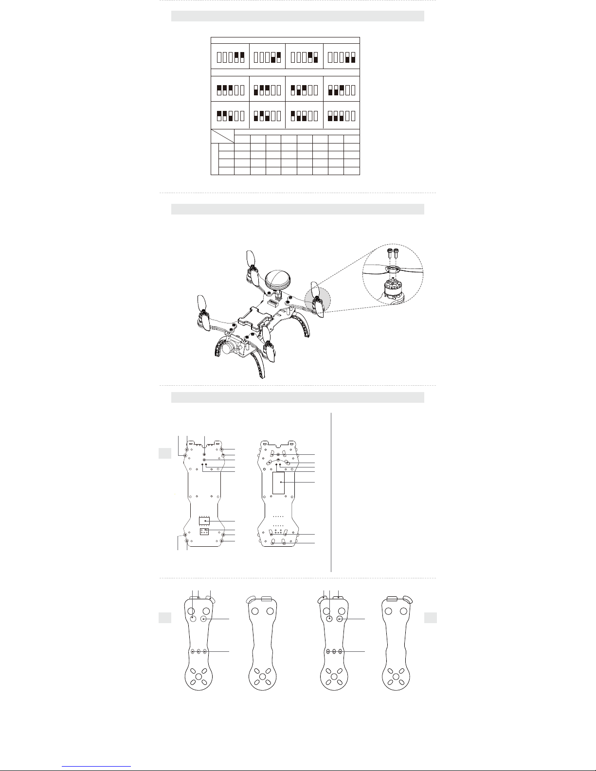
1. Mount the 5.8G antennas as picture shows.
2. Mount the propeller properly as below picture shows.
Connection diagram
Front
Front
Back
Front BackBack
[15] Positive solder pad for battery voltage
[20] Positive solder pad for battery voltage
[16] Negative solder pad for battery voltage
[21] Negative solder pad for battery voltage
[3] Positive solder pad for battery voltage
[2] Solder pad for esc signal wire
[5] Negative solder pad for esc signal
[4] Solder pad for esc signal wire
[6] Negative solder pad for battery voltage
[7] +5V
[8] GND
[17] +5V
[18] GND
[19] Flight controller
[1] Negative solder pad for esc signal
[13] Negative solder pad for esc signal
[14] Solder pad for esc signal wire
[12] Negative solder pad for esc signal
[11] Solder pad for esc signal wire
[10] 5.8G antennas pedestal
[9] 5.8G frequency-selection dial switch
[2]Positive solder pad for battery voltage
[3]Negative solder pad for battery voltage
[4]Negative solder pad for esc signal
[4]
[5]
[2] [3][1]
[15]
[1] [2] [3]
[4]
[6]
[7]
[8]
[9]
[10]
[11]
[12]
[13][14]
[16]
[17]
[18]
[20]
[21]
[1]Solder pad for esc signal wire
[5]Solder pad for motor
[2]Negative solder pad for esc signal
[3]Positive solder pad for battery voltage
[4]Solder pad for esc signal wire
[1]Negative solder pad for battery voltage
[5]Solder pad for motor
[2][1] [3]
[4]
[5]
Main board connectionESC connection for left arm
ESC connection for right arm
[19]
[5]
Dial switch 12345 to choose the required FR/CH for 32 channels.
Switch frequency selection
FR
CH
CH
CH
CH1
5865M
5733M
5705M
5740M
5685M
5760M 5780M 5800M 5820M 5840M 5860M 5880M
5665M
5752M 5771M 5790M
5645M
5809M
5885M
5828M
5905M
5847M
5925M
5866M
5945M
5845M 5825M 5805M 5785M 5765M 5745M 5725M
CH2 CH3 CH4 CH5 CH6 CH7 CH8
FR
FR
FR1
FR2
FR3
FR4
FR1 (A)
1 2 3 4 5
FR2 (B)
1 2 3 4 5
FR3 (C)
1 2 3 4 5
FR4 (D)
1 2 3 4 5
CH4
1 2 3 4 5
CH3
1 2 3 4 5
CH2
1 2 3 4 5
CH1
1 2 3 4 5
CH5
1 2 3 4 5
CH6
1 2 3 4 5
CH7
1 2 3 4 5
CH8
1 2 3 4 5
CW
CW
CCW
CCW
 Loading...