

Page 1

Page 2

Page 3

Preface
Copyright
This publication, including all photographs, illustrations and software, is protected under
international copyright laws, with all rights reserved. Neither this manual, nor any of the
material contained herein, may be reproduced without written consent of the author.
Version 1.1
Disclaimer
The information in this document is subject to change without notice. The manufacturer
makes no representations or warranties with respect to the contents hereof and specifically
disclaims any implied warranties of merchantability or fitness for any particular purpose.
The manufacturer reserves the right to revise this publication and to make changes from
time to time in the content hereof without obligation of the manufacturer to notify any
person of such revision or changes.
Trademark Recognition
Microsoft, MS-DOS and Windows are registered trademarks of Microsoft Corp.
nVIDIA is a registered trademark of nVIDIA Corporation
Other product names used in this manual are the properties of their respective owners and
are acknowledged.
Federal Communications Commission (FCC)
This equipment has been tested and found to comply with the limits for a Class B digital
device, pursuant to Part 15 of the FCC Rules. These limits are designed to provide reasonable protection against harmful interference in a residential installation. This equipment
generates, uses, and can radiate radio frequency energy and, if not installed and used in
accordance with the instructions, may cause harmful interference to radio communications.
However, there is no guarantee that interference will not occur in a particular installation.
If this equipment does cause harmful interference to radio or television reception, which
can be determined by turning the equipment off and on, the user is encouraged to try to
correct the interference by one or more of the following measures:
• Reorient or relocate the receiving antenna.
• Increase the separation between the equipment and the receiver.
• Connect the equipment onto an outlet on a circuit different from that to which
the receiver is connected.
• Consult the dealer or an experienced radio/TV technician for help.
Shielded interconnect cables and a shielded AC power cable must be employed with this
equipment to ensure compliance with the pertinent RF emission limits governing this
device. Changes or modifications not expressly approved by the system’s manufacturer
could void the user’s authority to operate the equipment.
Preface
Page 4

ii
Declaration of Conformity
This device complies with part 15 of the FCC rules. Operation is subject to the following
conditions:
• This device may not cause harmful interference, and
• This device must accept any interference received, including interference
that may cause undesired operation.
Canadian Department of Communications
This class B digital apparatus meets all requirements of the Canadian Interference-causing
Equipment Regulations.
Cet appareil numérique de la classe B respecte toutes les exigences du Réglement sur le
matériel brouilieur du Canada.
About the Manual
The manual consists of the following:
Chapter 1
Introducing the Motherboard
Chapter 2
Installing the Motherboard
Chapter 3
Using BIOS
Chapter 4
Using the Motherboard Software
Describes features of the motherboard.
Go to
Describes installation of motherboard
components.
Go to
Provides information on using the BIOS
Setup Utility.
Go to
Describes the motherboard software
Go to
H
H
H
H
page 1
page 7
page 25
page 51
Preface
Page 5

TT
ABLE OF CONTENTSABLE OF CONTENTS
T
ABLE OF CONTENTS
TT
ABLE OF CONTENTSABLE OF CONTENTS
Preface i
III
Chapter 1
Introducing the Motherboard 1
Introduction................................................................................................1
Features.......................................................................................................2
Motherboard Components.......................................................................4
1
Chapter 2
Installing the Motherboard 7
Safety Precautions......................................................................................7
Choosing a Computer Case.......................................................................7
Installing the Motherboard in a Case......................................................7
Checking Jumper Settings.........................................................................8
Setting Jumpers..............................................................................8
Checking Jumper Settings..............................................................9
Jumper Settings..............................................................................9
Connecting Case Components...............................................................10
Front Panel Header.....................................................................12
Installing Hardware...................................................................................12
Installing the Processor...............................................................12
Installing Memory Modules.........................................................14
Installing a Hard Disk Drive/CD-ROM/SATA Hard Drive........18
Installing a Floppy Diskette Drive...............................................19
Installing Add-on Cards..............................................................20
Connecting Optional Devices......................................................22
Connecting I/O Devices..........................................................................25
7 7
7
7 7
Chapter 3
Using BIOS 27
About the Setup Utility............................................................................27
Using BIOS................................................................................................29
27 27
27
27 27
The Standard Configuration........................................................27
Entering the Setup Utility..............................................................27
Updating the BIOS.......................................................................29
Standard CMOS Features...........................................................30
Advanced BIOS Features.............................................................32
Advanced Chipset Features.........................................................36
Page 6

iv
Integrated Peripherals.................................................................39
Power Management Setup...........................................................43
PNP/PCI Configurations.............................................................45
PC Health Status..........................................................................46
Load Fail-Safe Defaults.....................................................................47
Load Optimized Defaults.............................................................47
Set Supervisor/User Password....................................................47
Save & Exit Setup ...............................................................................48
Exit Without Saving......................................................................48
Chapter 4
51 51
51
51 51
Using the Motherboard Software 51
About the Software CD-ROM...............................................................51
Auto-installing under Windows 2000/XP.............................................51
Running Setup..............................................................................52
Manual Installation..................................................................................54
Utility Software Reference.......................................................................54
Multi-Language Translation
Page 7

Chapter 1
Introducing the Motherboard
Introduction
Thank you for choosing the GeForce6100SM-M motherboard. This motherboard is a high
performance, enhanced function motherboard that supports Socket AM2 AMD Athlon 64
FX/Athlon 64 X2 Dual-Core/Athlon 64/Sempron CPUs for high-end business or personal
desktop markets.
This motherboard is based on NVIDIA®ΜCP61Standard media and communications processor (MCP) for best desktop platform solution. MCP61S is a single-chip, highly integrated, high performance HyperTransport peripheral controller, unmatched by any other
single chip-device controller. This motherboard supports up to 16 GB of system memory
with DDR2 800/667/533. DIMMs, high resolution graphics via an PCI Express x 16 slot
(MCP61S only support PCI Express x8), native Ethernet MAC, USB 2.0, 6-channel audio
and SATA support with RAID function.
There is an advanced full set of I/O ports in the rear panel, including PS/2 mouse and
keyboard connectors, COM1, LPT1, four USB ports, one VGA port, one optional LAN
port, one optional 1394a port and audio jacks for microphone, line-in, and line-out. This
motherboard is designed in a Micro ATX form factor using a four-layer printed circuit board
and measures 244 mm x 224 mm.
1
Introducing the Motherboard
Page 8

2
Feature
Processor
This motherboard uses a Socket AM2 that carries the following features:
• Accommodates AMD Athlon 64 FX/Athlon 64 X2 Dual-Core/Athlon 64/Sempron
processors
• Supports up to 2000 MT/s HyperTransportTM (HT) interface Speeds
HyperTransportTM Technology is a point-to-point link between two devices, it enables
integrated circuits to exchange information at much higher speeds than currently available interconnect technologies.
Chipset
The NVIDIA®MCP61S is a single-chip with proven reliability and performance.
• HyperTransport x16 up and down links at up to 1.0 GHz to the AM2 CPUs
• support PCI Express x8 for external graphics
• PCI 2.3 interface at 33 MHz
• Support 2 SATA2 3.0 Gb/s devices
• Native 10/100 Ethernet MAC supported
• Eight USB 2.0 ports supported
• Fast ATA-133 IDE controller
• High Definition Audio Specification 1.0 compliant
Memory
• DDR2 800/667/533 DDR SDRAM with Dual Channel supported
• Accommodates two unbuffered DIMMs
• Up to 8 GB per DIMM with maximum memory size up to 16 GB
Audio
The onboard Audio provides the following features:
• Three Stereo DACs support 16/20/24-bit PCM format for 5.1 channel
audio solution
• ADCs support 44.1k/48k/96k sample rate
• Meets Microsoft WHQL/WLP 3.0x audio requirements
• Direct Sound 3D
• 8 channels of DAC support 24/20/16-bit PCM format for 7.1 audio solution
• Supports 192K/96K/48K/44.1KHz DAC sample rate
• Power support: Digital: 3.3V; Analog: 3.5V~5.25V
• Meets Microsoft WHQL/WLP 2.x audio requirements
• Direct Sound 3DTM compatible
• DolbyR Digital Encoder output for consumer electronic application
• Four Stereo DACs support 16/20/24-bit PCM format for 7.1 channel audio
solution
• ADCs support 48k/96k sample rate
• High quality differential CD input
• Power Support: Digital: 3.3V; Analog: 5.0V
• Meets Microsoft WHQL/WLP 2.0 audio requirements
• Direct Sound 3D
TM
compatible
TM
compatible
Introducing the Motherboard
Page 9

Onboard LAN (Optional)
The onboard LAN provides the following features:
• Supports 10 Mb/s and 100 Mb/s N-way Auto-negotiation operation
• Supports Wake-on-LAN function and remote wake-up
• Half/Full Duplex capability
• Integrated 10/100/1000 transceiver
• Supports PCI rev.2.3,32-bit,33/66 MHz
• Crossover Detection & Auto-Correction
• Wake-on-LAN and remote wake-up support
• 10BASE-T/100BASE-TX IEEE 802.3u fast Ethernet transceiver
• Low-power mode
• MII and 7-wire serial interface
1394a FireWire (Optional)
• Compliant with single chip host controller of IEEE Std 1394-1995 and IEEE
1394a-2000
• Integrated 400 Mb/s 2-port PHY for the PCI BUS
• 3.3V Power Supply with 5V Tolerant Inputs
Expansion Options
:
The motherboard comes with the following expansion options:
• One PCI Express x16 for Graphics Interface (MCP61S only support PCI
Express x8)
• One PCI Express x1 slot
• Two 32-bit PCI v2.3 compliant slots
• One IDE connectors supporting up to two IDE devices
• One floppy disk drive interface
• Two 7-pin SATA2 connectors
This motherboard supports Ultra DMA bus mastering with transfer rates of 133/100/66
MB/s.
Integrated I/O
The motherboard has a full set of I/O ports and connectors:
• Two PS/2 ports for mouse and keyboard
• One serial port
• One parallel port
• One VGA port
• Four USB ports
• One LAN port (optional)
• One 1394a port (optional)
• Audio jacks for microphone, line-in and line-out
BIOS Firmware
The motherboard uses Award BIOS that enables users to configure many system features
including the following:
• Power management
• Wake-up alarms
• CPU parameters
• CPU and memory timing
The firmware can also be used to set parameters for different processor clock speeds.
Some hardware specifications and software items are subject to change
without prior notice.
Introducing the Motherboard
3
Page 10
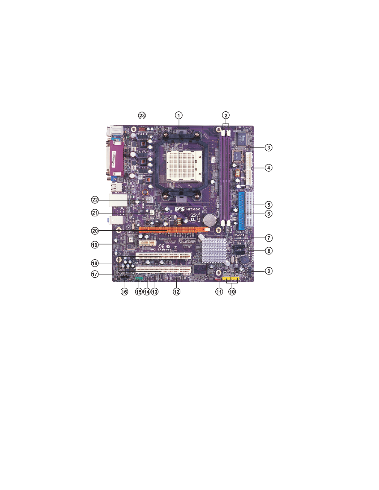
4
Motherboard Components
Introducing the Motherboard
Page 11

Table of Motherboard Components
LABEL COMPONENT
1 CPU Socket
2 DIMM1~2 240-pin DDR2 SDRAM slots
3 IRDA * Infrared header
4 FDD1 Floppy disk drive connector
5 ATX_POWER1 Standard 24-pin ATX power connector
6 IDE1 Primary IDE connector
7 PWR_FAN * Power cooling fan connector
8 SATA1~2 Serial ATA connectors
9 PANEL1 Front Panel switch/LED header
10 USB1~2 Front Panel USB headers
11 CLR_COMS Clear CMOS jumper
12 1394A1* 1394a header
13 WOL1* Wake on LAN connector
14 COM2 * Onboard serial port header
15 AUDIO1 Front panel audio header
16 CD_IN Analog audio output connector
17 SPDIFO1 * SPDIF out header
18 PCI1~2 32-bit add-on card slots
19 PCIEX1 PCI Express x1 slots
20 PCIEX16 PCI Express x16 graphics card slot
21 SYS_FAN1 System cooling fan connector
22 ATX12V1 4-pin +12V power connector
23 CPU_FAN1 CPU cooling fan connector
Socket AM2 for AMD Athlon 64 FX/Athlon 64
X2 Dual-Core/Athlon 64/Sempron processors
5
* Stands for optional component
This concludes Chapter 1. The next chapter explains how to install the motherboard.
Introducing the Motherboard
Page 12

6
Memo
Introducing the Motherboard
Page 13

Chapter 2
Installing the Motherboard
Safety Precautions
• Follow these safety precautions when installing the motherboard
• Wear a grounding strap attached to a grounded device to avoid damage from
static electricity
• Discharge static electricity by touching the metal case of a safely grounded
object before working on the motherboard
• Leave components in the static-proof bags they came in
• Hold all circuit boards by the edges. Do not bend circuit boards
Choosing a Computer Case
There are many types of computer cases on the market. The motherboard complies with
the specifications for the Micro ATX system case. Firstly, some features on the motherboard
are implemented by cabling connectors on the motherboard to indicators and switches on
the system case. Make sure that your case supports all the features required. Secondly, this
motherboard supports one or two floppy diskette drives and two enhanced IDE drives.
Make sure that your case has sufficient power and space for all drives that you intend to
install.
Most cases have a choice of I/O templates in the rear panel. Make sure that the I/O template
in the case matches the I/O ports installed on the rear edge of the motherboard.
This motherboard carries an Micro ATX form factor of 244 X 224 mm. Choose a case that
accommodates this form factor.
7
Installing the Motherboard in a Case
Refer to the following illustration and instructions for installing the motherboard in a case.
Most system cases have mounting brackets installed in the case, which correspond the holes
in the motherboard. Place the motherboard over the mounting brackets and secure the
motherboard onto the mounting brackets with screws.
Ensure that your case has an I/O template that supports the I/O ports and expansion slots
on your motherboard.
Installing the Motherboard
Page 14

8
Do not over-tighten the screws as this can stress the motherboard.
Checking Jumper Settings
This section explains how to set jumpers for correct configuration of the motherboard.
Setting Jumpers
Use the motherboard jumpers to set system configuration options. Jumpers with more than
one pin are numbered. When setting the jumpers, ensure that the jumper caps are placed on
the correct pins.
The illustrations show a 2-pin jumper. When
the jumper cap is placed on both pins, the
jumper is SHORT. If you remove the jumper
cap, or place the jumper cap on just one pin,
the jumper is OPEN.
This illustration shows a 3-pin jumper. Pins
1 and 2 are SHORT
SHORT OPEN
Installing the Motherboard
Page 15
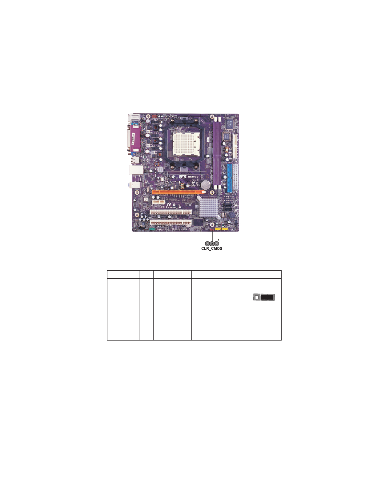
Checking Jumper Settings
The following illustration shows the location of the motherboard jumpers. Pin 1 is labeled.
9
Jumper Settings
Jumper
CLR_COMS 3-pin
Type
Description
CLEAR CMOS
Setting (default)
1-2: NORMAL
2-3: CLEAR
Before clearing the
CMOS, make sure to
turn the system off.
Installing the Motherboard
1
CLR_COMS
Page 16
10
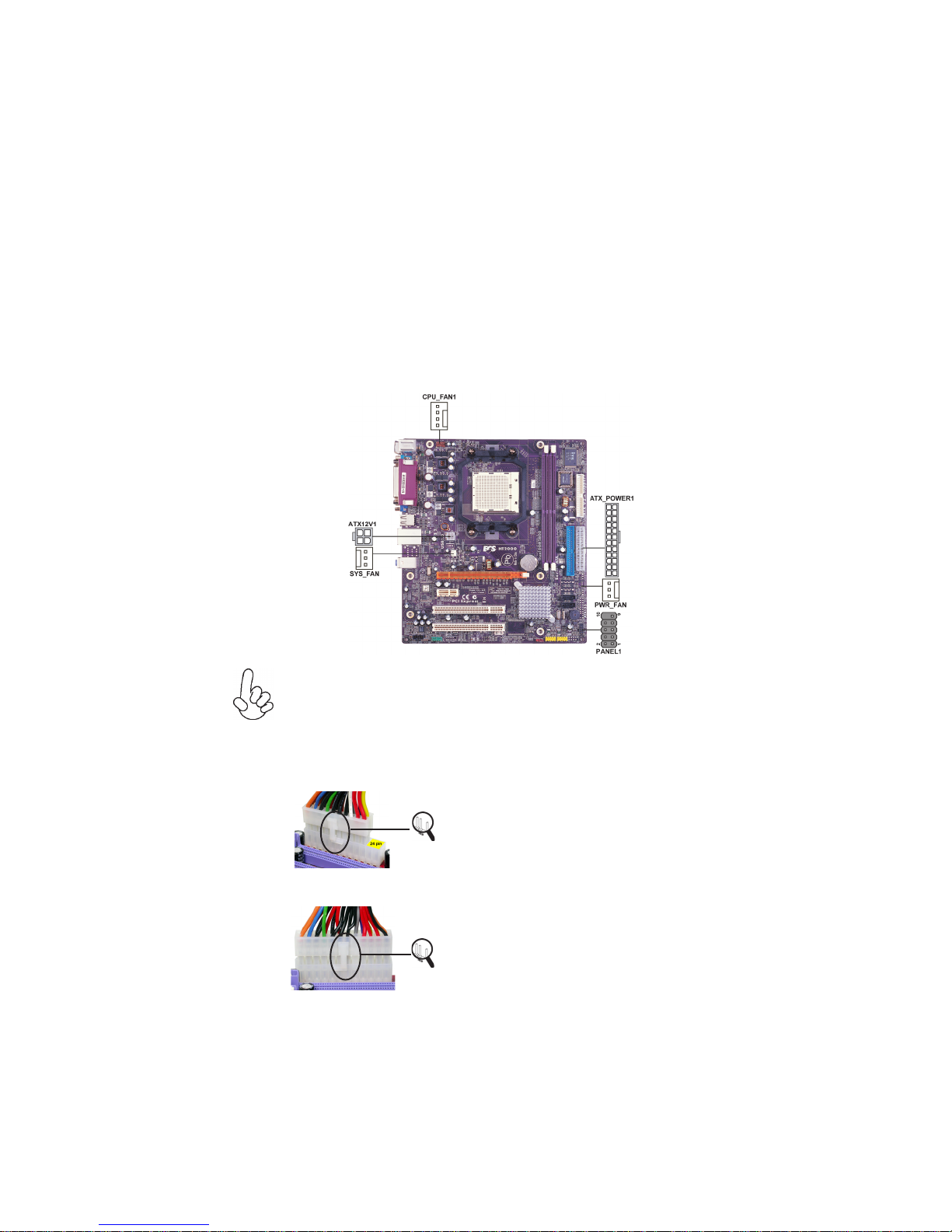
Connecting Case Components
After you have installed the motherboard into a case, you can begin connecting the
motherboard components. Refer to the following:
1 Connect the CPU cooling fan cable to CPU_FAN1.
2 Connect the power cooling fan connector to PWR_FAN.
3 Connect the system cooling fan connector to SYS_FAN1.
4 Connect the standard power supply connector to ATX_POWER1.
5 Connect the auxiliary case power supply connector to ATX12V1.
6 Connect the case switches and indicator LEDs to the PANEL1.
Connecting 20/24-pin power cable
Users please note that the 20-pin and 24-pin power cables can both be connected
to the ATX1 connector. With the 20-pin power cable, just align the 20-pin power
cable with the pin 1 of the ATX_POWER1 connector. However, using 20-pin
power cable may cause the system to become unbootable or unstable because of
insufficient electricity. A minimum power of 300W is recommended for a fullyconfigured system.
With ATX v1.x power supply, users please note
that when installing 20-pin power cable, the
latche of power cable falls on the left side of
the ATX_POWER1 connector latch, just as the
picture shows.
20-pin power cable
With ATX v2.x power supply, users please note
that when installing 24-pin power cable, the
latches of power cable cling s to the right side
of the ATX_POWER1 connector latach.
24-pin power cable
Installing the Motherboard
Page 17

CPU_FAN1/SYS_FAN1: Cooling FAN Power Connectors
11
Pin Signal Name
1 GND System Ground
2 +12V Power +12V
3 Sense Sensor
4 PWM CPU FAN control
Function
PWR_FAN: Cooling FAN Power Connector (Optional)
Pin Signal Name Function
1 GND System Ground
2 +12V Power +12V
3 Sense Sensor
ATX_POWER1: ATX 24-pin Power Connector
Pin Signal Name Pin Signal Name
1 +3.3V 13 +3.3V
2 +3.3V 14 -12V
3 Ground 15 COM
4 +5V 16 PS_ON
5 Ground 17 COM
6 +5V 18 COM
7 Ground 19 COM
8 PWRGD 20 -5V
9 +5VSB 21 +5V
10 +12V 22 +5V
11 +12V 23 +5V
12 +3.3V 24 COM
ATX12V1: ATX 12V Power Connector
Pin Signal Name
1 Ground
2 Ground
3 +12V
4 +12V
Installing the Motherboard
Page 18
12
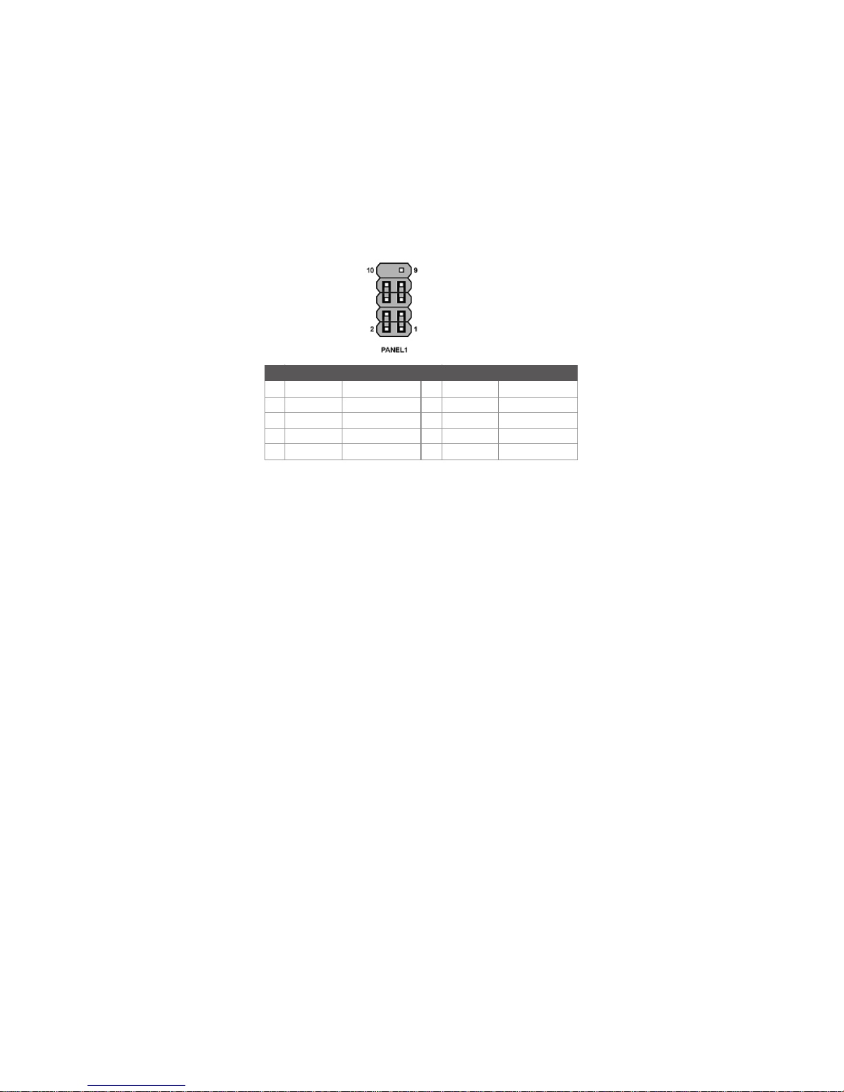
Front Panel Header
The front panel header (PANEL1) provides a standard set of switch and LED headers
commonly found on ATX or Micro ATX cases. Refer to the table below for information:
Pin Signal Function Pin Signal Function
1 HD_LED_P Hard disk LED (+)
3 HD_LED_N Hard disk LED (-)
5 RST_SW_N Reset Switch (-)
7 RST_SW_P Reset Switch (+)
9 RSVD Reserved
* MSG LED (dual color or single color)
Hard Drive Activity LED
Connecting pins 1 and 3 to a front panel mounted LED provides visual indication that data
is being read from or written to the hard drive. For the LED to function properly, an IDE
drive should be connected to the onboard IDE interface. The LED will also show activity for
devices connected to the SCSI (hard drive activity LED) connector.
Power/Sleep/Message waiting LED
2 FP PWR/SLP *MSG LED (+)
4 FP PWR/SLP *MSG LED (-)
6 PWR_SW_P Power Switch (+)
8 PWR_SW_N Power Switch (-)
10 Key No pin
Connecting pins 2 and 4 to a single or dual-color, front panel mounted LED provides power
on/off, sleep, and message waiting indication.
Reset Switch
Supporting the reset function requires connecting pin 5 and 7 to a momentary-contact
switch that is normally open. When the switch is closed, the board resets and runs POST.
Power Switch
Supporting the power on/off function requires connecting pins 6 and 8 to a momentarycontact switch that is normally open. The switch should maintain contact for at least 50 ms
to signal the power supply to switch on or off. The time requirement is due to internal debounce circuitry. After receiving a power on/off signal, at least two seconds elapses before
the power supply recognizes another on/off signal.
Installing the Motherboard
Page 19

Installing Hardware
Installing the Processor
Caution: When installing a CPU heatsink and cooling fan make sure that
you DO NOT scratch the motherboard or any of the surface-mount resistors
with the clip of the cooling fan. If the clip of the cooling fan scrapes across
the motherboard, you may cause serious damage to the motherboard or its
components.
On most motherboards, there are small surface-mount resistors near the
processor socket, which may be damaged if the cooling fan is carelessly
installed.
Avoid using cooling fans with sharp edges on the fan casing and the clips.
Also, install the cooling fan in a well-lit work area so that you can clearly see
the motherboard and processor socket.
Before installing the Processor
This motherboard automatically determines the CPU clock frequency and system bus
frequency for the processor. You may be able to change these settings by making changes to
jumpers on the motherboard, or changing the settings in the system Setup Utility. We
strongly recommend that you do not over-clock processors or other components to run
faster than their rated speed.
Warning: Over-clocking components can adversely affect the reliability of
the system and introduce errors into your system. Over-clocking can permanently damage the motherboard by generating excess heat in components
that are run beyond the rated limits.
13
This motherboard has a Socket AM2 processor socket. When choosing a processor, consider the performance requirements of the system. Performance is based on the processor
design, the clock speed and system bus frequency of the processor, and the quantity of
internal cache memory and external cache memory.
Installing the Motherboard
Page 20

14
CPU Installation Procedure
The following illustration shows CPU installation components.
1 Install your CPU. Pull up the lever away from the
socket and lift up to 90-degree angle.
2 Locate the CPU cut edge (the corner with the pin
hold noticeably missing). Align and insert the CPU
correctly.
3 Press the lever down and apply thermal grease on
top of the CPU.
4 Put the CPU Fan down on the retention module and
snap the four retention legs of the cooling fan into
place.
5 Flip the levers over to lock the heat sink in place and
connect the CPU cooling Fan power cable to the
CPUFAN connector. This completes the installation.
To achieve better airflow rates and heat dissipation, we suggest that you use
a high quality fan with 4800 rpm at least. CPU fan and heatsink installation
procedures may vary with the type of CPU fan/heatsink supplied. The form
and size of fan/heatsink may also vary.
Installing the Motherboard
Page 21
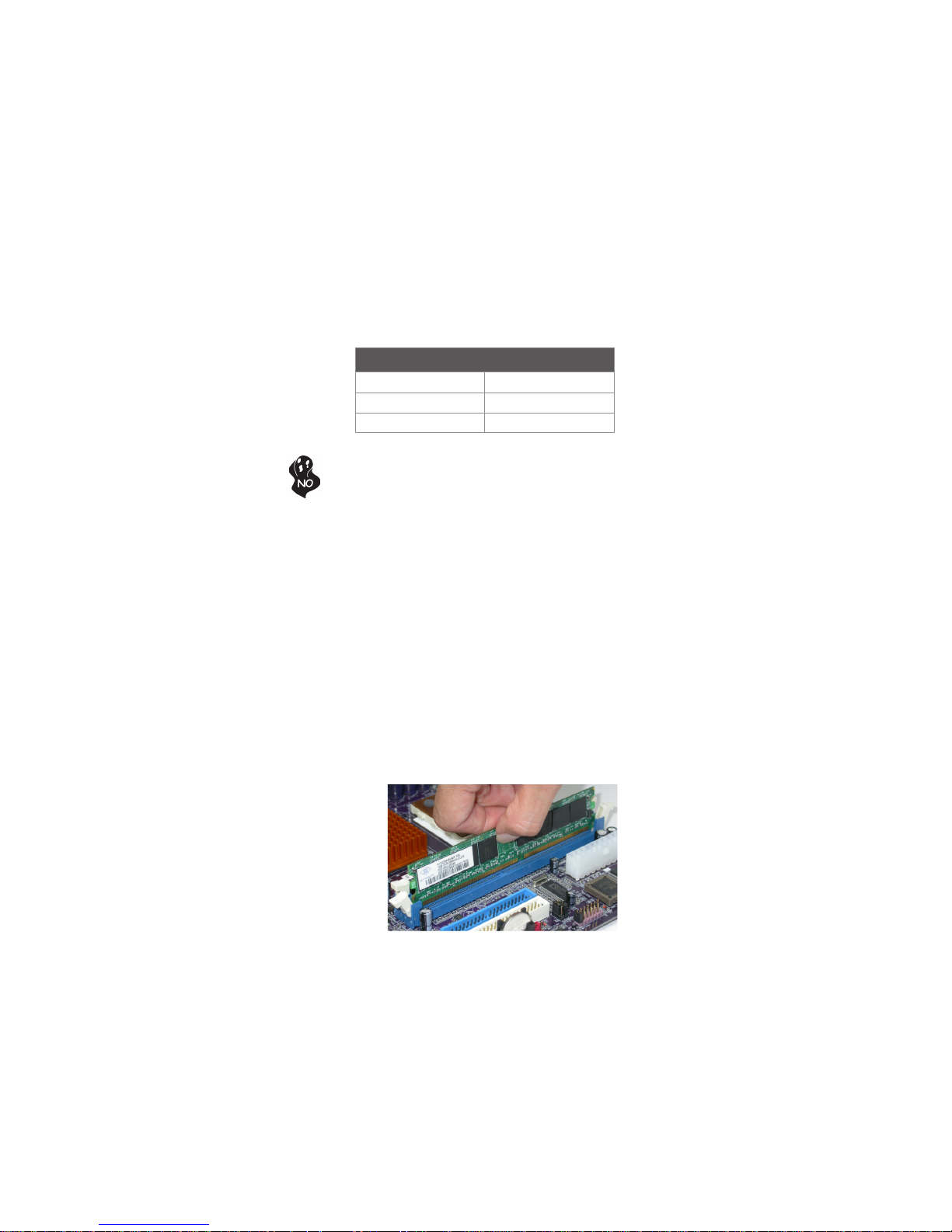
Installing Memory Modules
This motherboard accommodates two 240-pin unbuffered DIMMs and supports DDR2 800
/667/533 DDR2 SDRAM. You must install at least one module in any of the two slots. Each
module can be installed with 8 GB of memory; the total memory capacity is 16 GB.
DDR2 SDRAM memory module table
Memory module Memory Bus
DDR2 533 266 MHz
DDR2 667 333 MHz
DDR2 800 400 MHz
Do not remove any memory module from its antistatic packaging until you
are ready to install it on the motherboard. Handle the modules only by
their edges. Do not touch the components or metal parts. Always wear a
grounding strap when you handle the modules.
Installation Procedure
Refer to the following to install the memory modules.
1 This motherboard supports unbuffered DDR2 SDRAM only.
2 Push the latches on each side of the DIMM slot down.
3 Align the memory module with the slot. The DIMM slots are keyed with notches
and the DIMMs are keyed with cutouts so that they can only be installed
correctly.
4 Check that the cutouts on the DIMM module edge connector match the notches
in the DIMM slot.
5 Install the DIMM module into the slot and press it firmly down until it seats
correctly. The slot latches are levered upwards and latch on to the edges of
the DIMM.
6 Install any remaining DIMM modules.
15
Installing the Motherboard
Page 22

16
Table A: Unbuffered DIMM Support for Socket AM2 CPU
DRAM
Speed
DDR2-400 - Any 1T 002F_2F2Fh X011_1222h
DDR2-400 Any Any 2T 002F_2F2Fh X011_1322h
DDR2-533 - Any 1T 002F_2F2Fh X011_1222h
DDR2-533
DDR2-533 SRx8 SRx8 2T 0000_2F2Fh X011_1322h
DDR2-533 DRx8 DRx8 2T 0034_2F2Fh X011_1322 h
DDR2-533
DDR2-533
DDR2-667 - Any 1T 0020_2020h X011_1222h
DDR2-667
DDR2-667 SRx8 SRx8 2T 0030_2020h X011_1322 h
DDR2-667 DRx8 DRx8 2T 002B_2020h X011_1322 h
DDR2-667
DDR2-667
DDR2-800 - Any 2T 0020_2520h X011_3222h
DDR2-800 Any An y 2T 0020 _2520h X011_3222h
1. SRx16=Single Rank x16 DIMM
SRx8=Single Rank x8 DIMM
DRx16=Dual Rank x16 DIMM
DRx8= Dual Rank x8 DIM M
1
DIMM1
DIMM21
SRx16 SRx16
SRx16 SRx8
SRx8 SRx16
DRx8 SRx16
SRx16 DRx8
DRx8 SRx8
SRx8 DRx8
SRx16 SRx16
SRx16 SRx8
SRx8 SRx16
DRx8 SRx16
SRx16 DRx8
DRx8 SRx8
SRx8 DRx8
Timing
Address Timing
Mode
Control Register
2T 002F_2F2Fh X011_1322h
2T 0038_2F2Fh X011_1322h
2T 0037_2F2Fh X011_1322h
2T 0020_2020h X011_1322h
2T 002C_2020h X011_1322h
2T 002A_2020h X011_1322h
Output Driver
Compensation
Control Register
Table B: DDR2 (memory module) QVL (Qualified Vendor List)
The following DDR2 memory modules have been tested and qualified for use with this
motherboard.
Installing the Motherboard
Page 23
17
Type Size Vendor Module Name
4PB11D9CHM
VC256MB533D2 4PB11 D9CHM
SAMSUNG K4T510830B-GCD5
SAMSUNG K4T51083QF-ZCD5
HYB18T512800AF37
HYB818T512800AF373346 778
Hynix KVR533D2N4/512 HY5PS12821
Hynix KVR533D2N4/512HY5PS 56821
DDR2 533
DDR2 667
DDR2 800
CORSAIR
CORSAIR
Eipida 04180WB00
Infineon Kingston HYB18T512260AF-3. 7
256 MB
Kingston ELPIDA E5 116AF-5C-E HYB18T512260AF-3.7
Kingmax Hynix HY5PS121621
Nanya NT5TU32M16AG-37B
Ramaxel ELPIDA E5116AF-5C-E
AEONEON AET660UD00-370A98X AET660UD00-370A98 Z
AEONEON AET93F370A98Z
Auspis DR2504-206IK
CORSAIR 4PB11D9 CHM
CORSAIR
Eipida 04180WB01
G.SKILL G76 GT
512 MB
Infineon
Kingmax Hynix HY5PS121621FP-C4
Kingston
PQI PQC2648S3
Ramaxel ELPIDA E5116AF-5C-E
Samsung K4T51083QC
Twinmos Hynix 8D22JB-HX Elpida 8D22JB-ED
Apacer AM4B5708GEJ-5D Eipida E5108AB-5C-E
Geil AG8AKT5H120004
Kingmax KKEA88E4AAKKG-37
1 GB
UMAX U2S12030TP-5C
UNIFOSA ELPIDA E5108AE-6E-E
Infineon HYS64T325001HU-3- A
256 MB
A-DATA Eipida E5108AB-5C-E
Corsair ValusSELECT 32M8CEC ValusSelect M11100 513
GEIL GL2L64MO88BA18W
Hynix HY818T512
Infinity 0547W64M8
512 MB
Kingston D6408TE8EWL3
PQI E5108AE-6E-E
SAMSUNG K4T51083QC K4T56083QF-ZCE6
SIS SLX246M8-T6E
SyncMAX 64MX8 D2-F
Transcend SAMSUNG K4T51083QC
Apacer Eipida E5108AB-6E-E
Infineon HYB18T512800AF3S
1 GB
Kingston D6408TE8EWL3
Team T2D648MT-6
Apacer 78.91Q9K.AUC
Infineon Hynix HYS64T64020HU-2.5 -A
512 MB
Kingmax NT5TU64M8BE-25C
SyncMAX PC2-8004-4-4 R050075B
Kingbox DDR264082200-3
Team T2D648MT-8
1 GB
Transcend Hynix HY5PS12821AFP-S5
Installing the Motherboard
Page 24

18
Installing a Hard Disk Drive/CD-ROM/SATA Hard Drive
This section describes how to install IDE devices such as a hard disk drive and a CD-ROM
drive.
About IDE Devices
Your motherboard has one IDE interface. An IDE ribbon cable supporting two IDE devices
is bundled with the motherboard.
You must orient the cable connector so that the pin1 (color) edge of the
cable corresponds to the pin 1 of the I/O port connector.
IDE1: Primary IDE Connector
The first hard drive should always be connected to IDE1.
IDE devices enclose jumpers or switches used to set the IDE device as MASTER or SLAVE.
Refer to the IDE device user’s manual. Installing two IDE devices on one cable, ensure that
one device is set to MASTER and the other device is set to SLAVE. The documentation of
your IDE device explains how to do this.
About UltraDMA
This motherboard supports UltraDMA 133/100/66. UDMA is a technology that accelerates
the performance of devices in the IDE channel. To maximize performance, install IDE
devices that support UDMA and use 80-pin IDE cables that support UDMA 133/100/66.
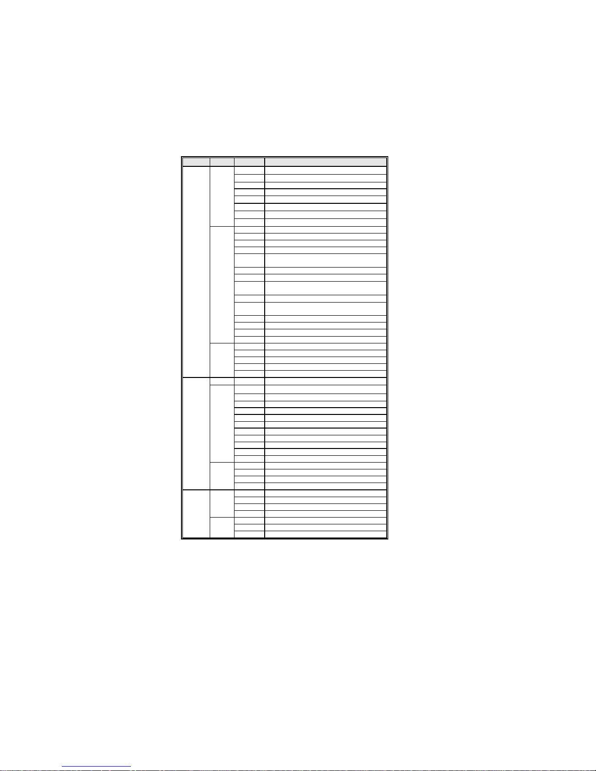
About SATA Connectors
Your motherboard features two SATA connectors supporting a total of two drives. SATA
refers to Serial ATA (Advanced Technology Attachment) is the standard interface for the
IDE hard drives which are currently used in most PCs. These connectors are well designed
and will only fit in one orientation. Locate the SATA connectors on the motherboard and
follow the illustration below to install the SATA hard drives.
Installing Serial ATA Hard Drives
To install the Serial ATA (SATA) hard drives, use the SATA cable that supports the Serial
ATA protocol. This SATA cable comes with an SATA power cable. You can connect either
end of the SATA cable to the SATA hard drive or the connector on the motherboard.
SATA cable (optional)
SATA power cable (optional)
Installing the Motherboard
Page 25
Refer to the illustration below for proper installation:
1 Attach either cable end to the connector on the motherboard.
2 Attach the other cable end to the SATA hard drive.
3 Attach the SATA power cable to the SATA hard drive and connect the other
end to the power supply.
This motherboard does not support the “Hot-Plug” function.
Installing a Floppy Diskette Drive
The motherboard has a floppy diskette drive (FDD1) interface and ships with a diskette
drive ribbon cable that supports one or two floppy diskette drives. You can install a 5.25inch drive and a 3.5-inch drive with various capacities. The floppy diskette drive cable has
one type of connector for a 5.25-inch drive and another type of connector for a 3.5-inch
drive.
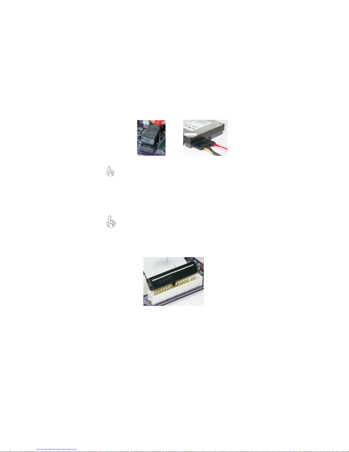
FDD1: Floppy Disk Connector
This connector supports the provided floppy drive ribbon cable. After connecting the single
end to the onboard floppy connector, connect the remaining plugs on the other end to the
floppy drives correspondingly.
You must orient the cable connector so that the pin 1 (color) edge of the
cable corresponds to the pin 1 of the I/O port connector.
19
Installing the Motherboard
Page 26
20
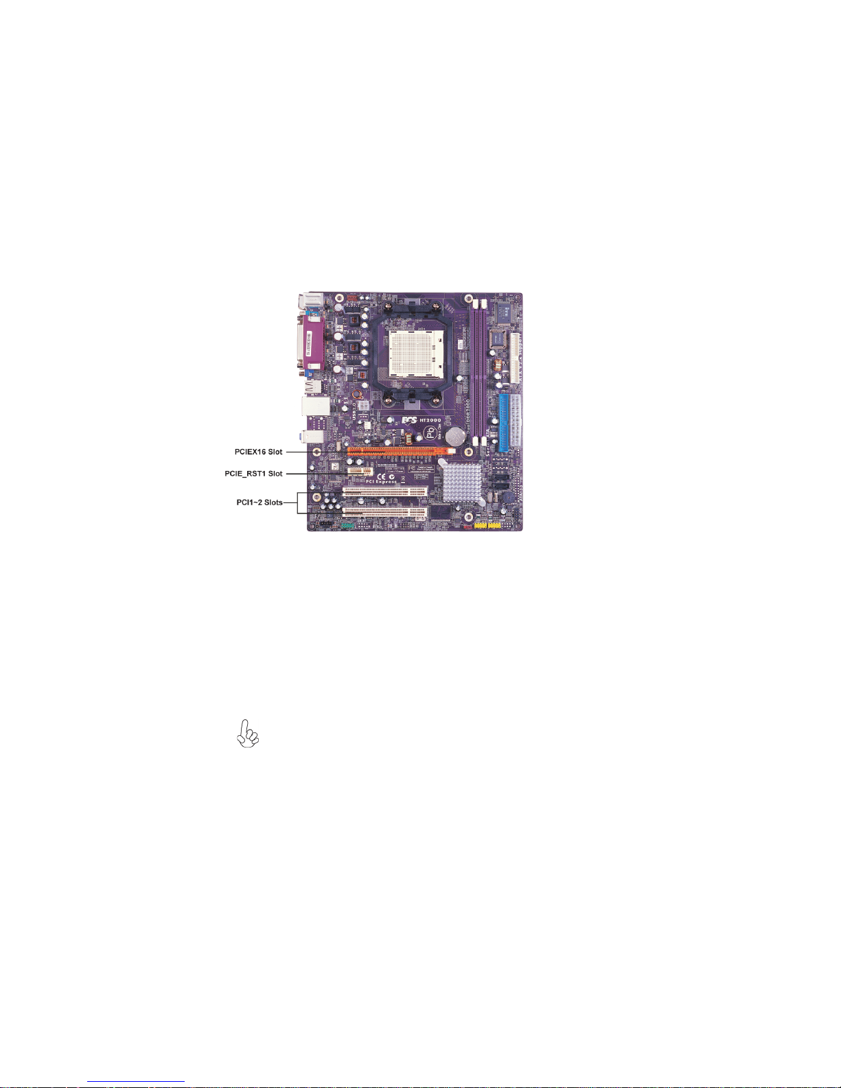
Installing Add-on Cards
The slots on this motherboard are designed to hold expansion cards and connect them to the
system bus. Expansion slots are a means of adding or enhancing the motherboard’s features
and capabilities. With these efficient facilities, you can increase the motherboard’s capabilities by adding hardware that performs tasks that are not part of the basic system.
PCIEX16 Slot The PCI Express x16 slot is used to install an external PCI Express
PCIE_RST1
Slot
PCI1~2 Slots
graphics card that is fully compliant to the PCI Express Base Specification revision 1.0a.
The PCI Express x1 slot is fully compliant to the PCI Express Base
Specification revision 1.0a as well.
This motherboard is equipped with two standard PCI slots. PCI stands for
Peripheral Component Interconnect and is a bus standard for expansion
cards, which for the most part, is a supplement of the older ISA bus
standard. The PCI slots on this board are PCI v2.3 compliant.
Before installing an add-on card, check the documentation for the card
carefully. If the card is not Plug and Play, you may have to manually
configure the card before installation.
Installing the Motherboard
Page 27
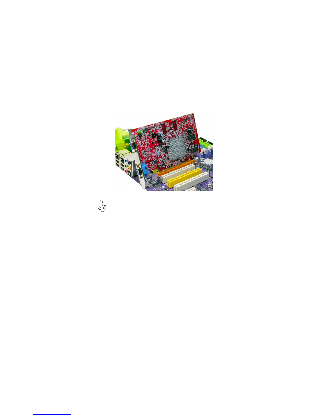
Follow these instructions to install an add-on card:
1 Remove a blanking plate from the system case corresponding to the slot you
are going to use.
2 Install the edge connector of the add-on card into the expansion slot. Ensure
that the edge connector is correctly seated in the slot.
3 Secure the metal bracket of the card to the system case with a screw.
For some add-on cards, for example graphics adapters and network adapters, you have to install drivers and software before you can begin using the
add-on card.
21
Installing the Motherboard
Page 28

22
Connecting Optional Devices
Refer to the following for information on connecting the motherboard’s optional devices:
AUDIO1: Front Panel Audio header
This header allows the user to install auxiliary front-oriented microphone and line-out ports
for easier access.
Pin Signal Name Function
1 AUD_MIC Front Panel Microphone input signal
2 AUD_GND Ground used by Analog Audio Circuits
3 AUD_MIC_BIAS Microphone Power
4 AUD_VCC Filtered+5V used by Analog Audio Circuits
5 AUD_F_R Right Channel Audio signal to Front Panel
6 AUD_RET_ R Right Channel Audio signal to Rear Panel
7 REVD Reserved
8 Key No Pin
9 AUD_F_L Left Channel Audio signal to Front Panel
10 AUD_RET_ L Left Channel Audio signal to Rear Panel
Pin Signal Name
Pin Signal Name Function
1 PORT 1L 2 AUD_GND
3 PORT 1R 4 PRESENCE#
5 PORT 2R 6 SENSE1_RETURN
7 SENSE_SEND 8 KEY
9 PORT 2L 10 SENSE2_RETURN
Pin Signal Name
Installing the Motherboard
Page 29

SATA1~2: Serial ATA connectors
These connectors are used to support the new Serial ATA devices for the highest date
transfer rates (3 Gb/s ), simpler disk drive cabling and easier PC assembly. It eliminates
limitations of the current Parallel ATA interface. But maintains register compatibility and
software compatibility with Parallel ATA.
Pin Signal Name
1 Ground 2 TX+
3 TX- 4 Ground
5 RX- 6 RX+
7 Ground - -
Pin Signal Name
USB1~2: Front Panel USB headers
The motherboard has two USB ports installed on the rear edge I/O port array. Additionally,
some computer cases have USB ports at the front of the case. If you have this kind of case,
use auxiliary USB connector to connect the front-mounted ports to the motherboard.
23
Pin Signal Name
1 USBPWR Front Panel USB Power
2 USBPWR Front Panel USB Power
3 USB_FP_P0- USB Port 0 Negative Signal
4 USB_FP_P1- USB Port 1 Negative Signal
5 USB_FP_P0+ USB Port 0 Positive Signal
6 USB_FP_P1+ USB Port 1 Positive Signal
7 GND Ground
8 GND Ground
9 Key No pin
10 NC Not connected
Please make sure that the USB cable has the same pin assignment as indicated above. A different pin assignment may cause damage or system hangup.
Function
1394A1: Onboard IEEE 1394a header (Optional)
Connect this header to any device with IEEE 1394a interface.
Pin Signal Name
Pin Signal Name Function
1 TPA+ 2 TPA-
3 GND 4 GND
5 TPB+ 6 TPB-
7 Cable-Power 8 Cable-Power
9 Key Pin 10 GND
Pin Signal Name
IrDA: Infrared header (Optional)
The motherboard supports an Infrared (IRDA) data port. Infrared ports allow the wireless
exchange of information between your computer and similarly equipped devices such as
printers, laptops, Personal Digital Assistants (PDAs), and other computers.
Installing the Motherboard
Page 30

24
Pin Signal Name Function
1 Not Assigned Not assigned
2 Key N o pin
3 +5V IR Power
4 GND Ground
5 IR_TX IrDA serial output
6 IR_RX IrDA serial input
COM2: Onboard serial port header (Optional)
Connect a serial port extension bracket to this header to add a second serial port to your
system.
Pin Signal Name Function
1 NDCDB Data carry detect
2 NSINB Serial Data In
3 NSOUTB Serial Date Out
4 NDTRB Data terminal ready
5 GND Ground
6 NDSRB Date set ready
7 NRTSB Request to send
8 NCTSB Clear to send
9 NRIB Ring Indicator
10 Key No pin
CD_IN: Analog audio input connector
Pin Signal Name Function
1 CD_L Left CD-in signal
2 GND Ground
3 GND Ground
4 CD_R Right CD-in signal
SPDIFO1: SPDIF out header (Optional)
This is an optional header that provides an S/PDIF (Sony/Philips Digital Interface) output
to digital multimedia device through optical fiber or coaxial connector.
Pin Signal Name Function
1 SPDIF SPDIF digital output
2 +5VA 5V analog Power
3 Key N o pin
4 GND Ground
WOL1: Wake On LAN Connector (Optional)
If you haveinstalled a LAN card, use the cable provided with the card to plug into the
motherboard WOL connector. This enables the Wake On LAN (WOL) feature. When your
system id in a power-saving mode, any LAN signal automatically resumes the system. You
must enable this item using the Power Management page of the Setup Utility.
Pin Signal Name
1 5VSB +5V stand by power
2 GND Ground
3 Ring# Wake up signal
Function
Installing the Motherboard
Page 31

Connecting I/O Devices
The backplane of the motherboard has the following I/O ports:
PS2 Mouse Use the upper PS/2 port to connect a PS/2 pointing device.
PS2 Keyboard Use the lower PS/2 port to connect a PS/2 keyboard.
Parallel Port (LPT1) Use LPT1 to connect printers or other parallel communications
devices.
Serial Port Use the COM port to connect serial devices such as mice or
(COM1) fax/modems. COM1 is identified by the system as COM1/3.
LAN Port (optional) Connect an RJ-45 jack to the LAN port to connect your computer
to the Network.
25
USB Ports Use the USB ports to connect USB devices.
1394a Port (optional) Use the 1394a port to connect 1394 devices.
Audio Ports
This motherboard may adopt 8-channel audio ports that correspond to the
A,B, C, and E port respectively. In addition, all of the 3 ports, B, C, and E
provide users with both right & left channels individually. Users please refer
to the following note for specific port function definition.
This concludes Chapter 2. The next chapter covers the BIOS.
Use the three audio jacks to connect audio devices. The first jack
is for stereo line-in signal.The second jack is for stereo line-out
signal. The third jack is for microphone.
A: Center & Woofer D: Line-in
B: Back Surround E: Front Out
C: Side Surround F: Mic_in Rear
The above port definition can be changed to audio input or
audio output by changing the driver utility setting.
Installing the Motherboard
Page 32

26
Memo
Installing the Motherboard
Page 33

Chapter 3
Using BIOS
About the Setup Utility
The computer uses the latest Award BIOS with support for Windows Plug and Play. The
CMOS chip on the motherboard contains the ROM setup instructions for configuring the
motherboard BIOS.
The BIOS (Basic Input and Output System) Setup Utility displays the system’s configuration status and provides you with options to set system parameters. The parameters are
stored in battery-backed-up CMOS RAM that saves this information when the power is
turned off. When the system is turned back on, the system is configured with the values you
stored in CMOS.
The BIOS Setup Utility enables you to configure:
• Hard drives, diskette drives and peripherals
• Video display type and display options
• Password protection from unauthorized use
• Power Management features
The settings made in the Setup Utility affect how the computer performs. Before using the
Setup Utility, ensure that you understand the Setup Utility options.
This chapter provides explanations for Setup Utility options.
27
The Standard Configuration
A standard configuration has already been set in the Setup Utility. However, we recommend
that you read this chapter in case you need to make any changes in the future.
This Setup Utility should be used:
• when changing the system configuration
• when a configuration error is detected and you are prompted to make changes
to the Setup Utility
• when trying to resolve IRQ conflicts
• when making changes to the Power Management configuration
• when changing the password or making other changes to the Security Setup
Entering the Setup Utility
When you power on the system, BIOS enters the Power-On Self Test (POST) routines.
POST is a series of built-in diagnostics performed by the BIOS. After the POST routines are
completed, the following message appears:
Using BIOS
Page 34

28
Press DEL to enter SETUP
Pressing the delete key accesses the BIOS Setup Utility:
Phoenix-Award WorkstationBIOS CMOS Setup Utility:
Standard CMOS Features
Advanced BIOS Features
Advanced Chipset Features
Integrated Peripherals
Power Management Setup
PnP/PCI Configurations
PC Health Status
Esc: Quit
F10: Save & Exit Setup
Time, Date, Hard Disk Type...
Load Fail-Safe Defaults
Load optimized Defaults
Set Supervisor Password
Set User Password
Save & Exit Setup
Exit Without Saving
BIOS Navigation Keys
The BIOS navigation keys are listed below:
KEY FUNCTION
Enter
+/-/PU/PD
ESC
F1
F5
F7
F6
F10
Move
Select
Value
Exits the current menu
General Help
Previous Values
Optimized Defaults
Fail-Safe Defaults
Save
: Select Item
Using BIOS
Page 35

Updating the BIOS
You can download and install updated BIOS for this motherboard from the manufacturer’s
Web site. New BIOS provides support for new peripherals, improvements in performance,
or fixes for known bugs. Install new BIOS as follows:
1 If your motherboard has a BIOS protection jumper, change the setting to allow
BIOS flashing.
2 If your motherboard has an item called Firmware Write Protect in Advanced
BIOS features, disable it. (Firmware Write Protect prevents BIOS from being
overwritten.
3 Create a bootable system disk. (Refer to Windows online help for information
on creating a bootable system disk.)
4 Download the Flash Utility and new BIOS file from the manufacturer’s Web
site. Copy these files to the system diskette you created in Step 3.
5 Turn off your computer and insert the system diskette in your
computer’s diskette drive. (You might need to run the Setup Utility and change
the boot priority items on the Advanced BIOS Features Setup page, to force
your computer to boot from the floppy diskette drive first.)
6 At the A:\ prompt, type the Flash Utility program name and press <Enter>.
7 Type the filename of the new BIOS in the “File Name to Program” text box.
Follow the onscreen directions to update the motherboard BIOS.
8 When the installation is complete, remove the floppy diskette from the diskette
drive and restart your computer. If your motherboard has a Flash BIOS jumper,
reset the jumper to protect the newly installed BIOS from being overwritten.
Using BIOS
When you start the Setup Utility, the main menu appears. The main menu of the Setup
Utility displays a list of the options that are available. A highlight indicates which option is
currently selected. Use the cursor arrow keys to move the highlight to other options. When
an option is highlighted, execute the option by pressing <Enter>.
29
Some options lead to pop-up dialog boxes that prompt you to verify that you wish to
execute that option. Other options lead to dialog boxes that prompt you for information.
Some options (marked with a triangle
values for the option. Use the cursor arrow keys to scroll through the items in the submenu.
In this manual, default values are enclosed in parenthesis. Submenu items are denoted by a
triangle
.
) lead to submenus that enable you to change the
Using BIOS
Page 36

30
Standard CMOS Features
This option displays basic information about your system.
Phoenix-Award WorkstationBIOS CMOS Setup Utility
Date (mm:dd:yy) We d, Jan.1 2006
Time (hh:mm:ss) 0 : 54 : 28
IDE Channel 0 Master [PIONEER DVD-ROM DVD]
IDE Channel 0 Slave [None]
IDE Channel 2 Master [WDC WD1600JS-22MHB0]
IDE Channel 3 Master [None]
IDE Channel 4 Master [None]
IDE Channel 5 Master [None]
Drive A [1.44M, 3.5 in.]
Video [EGA/VGA]
Halt On Setting [All, But Keyboard]
Base Memory 640K
Extended Memory 523264K
Total Memory 524288K
: Move Enter: Select +/-/PU/PD:Value F10:Save ESC:Exit F1: General Help
F5:Previous Values F6: Fail-Safe Defaults F7:Optimized Defaults
Date and Time
The Date and Time items show the current date and time on the computer. If
you are running a Windows OS, these items are automatically updated whenever you make
changes to the Windows Date and Time Properties utility.
IDE Devices (None)
Your computer has two IDE channels (Primary and Secondary) and each channel can be
installed with one or two devices (Master and Slave). Use these items to
configure each device on the IDE channel.
Standard CMOS Features
Item Help
Menu Level
Change the day, month,
year and century
Press <Enter> to display the IDE submenu:
Phoenix-Award WorkstationBIOS CMOS Setup Utility
IDE HDD Auto-Detection [Press Enter]
IDE Channel 0 Master [Auto]
Access Mode [Auto]
Capacity 80 GB
Cylinder 38309
Head 16
Precomp 0
Landing Zone 38308
Sector 255
: Move Enter: Select +/-/PU/PD:Value F10:Save ESC:Exit F1: General Help
F5:Previous Values F6: Fail-Safe Defaults F7:Optimized Defaults
IDE Channel 0 Master
Using BIOS
Item Help
Menu Level
To auto-detect the
HDD’s size, head... on
this channel
Page 37

IDE HDD Auto-Detection
Press <Enter> while this item is highlighted to prompt the Setup Utility to automatically
detect and configure an IDE device on the IDE channel.
If you are setting up a new hard disk drive that supports LBA mode, more
than one line will appear in the parameter box. Choose the line that lists
LBA for an LBA drive.
IDE Channel 0/2/3/4/5 Master & IDE Channel 0 Slave
Leave this item at Auto to enable the system to automatically detect and configure IDE
devices on the channel. If it fails to find a device, change the value to Manual and then
manually configure the drive by entering the characteristics of the drive in the items
described below.
Before attempting to configure a hard disk drive, ensure that you have the
configuration information supplied by the manufacturer of your hard drive.
Incorrect settings can result in your system not recognizing the installed
hard disk.
Access Mode (Auto)
This item defines ways that can be used to access IDE hard disks such as LBA (Large Block
Addressing). Leave this value at Auto and the system will automatically decide the fastest
way to access the hard disk drive.
Press <Esc> to return to the Standard CMOS Features page.
Drive A (1.44M, 3.5 in.)
This item defines the characteristics of any diskette drive attached to the system.
Video (EGA/VGA)
This item defines the video mode of the system. The motherboard has a built-in VGA
graphics system; you must leave this item at the default value.
Halt On (All, But Keyboard)
This item defines the operation of the system POST (Power On Self Test) routine. You
can use this item to select which types of errors in the POST are sufficient to halt the
system.
Base Memory, Extended Memory, and Total Memory
These items are automatically detected by the system at start up time. These are
display-only fields. You cannot make changes to these fields.
31
Using BIOS
Page 38

32
Advanced BIOS Features
This option defines advanced information about your system.
CPU Feature [Press Enter]
Removable Device Priority
Hard Disk Boot Priority
CD-ROM Boot Priority
Network Boot Priority [Press
CPU Internal Cache [Enabled]
External Cache [Enabled]
Quick Power On Self Test [Enabled]
First Boot Device [Removable]
Second Boot Device [Hard Disk]
Third Boot Device [CDROM]
Boot Other Device [Enabled]
Boot Up Floppy Seek [Disabled]
Boot Up NumLock Status [On]
Gate A20 Option [Fast]
Typematic Rate Setting [Disabled]
Typematic Rate (Chars/Sec) 6
X
Typematic Delay (Msec) 250
X
Security Option [Setup]
CPU Feature (Press Enter)
Scroll to this item and press <Enter> to view the following screen:
NPT Fid Control [Auto]
NPT Vid Control [Auto]
AMD K8 Cool & Quite Control [Auto]
Phoenix-Award WorkstationBIOS CMOS Setup Utility
Advanced BIOS Features
[Press Enter]
[Press Enter]
[Press Enter]
Enter]
Item Help
Menu Level
Select Removable
Boot Device Priority
: Move Enter: Select +/-/PU/PD:Value F10:Save ESC:Exit F1: General Help
F5:Previous Values F6:Fail-Safe Defaults F7:Optimized Defaults
Phoenix-Award WorkstationBIOS CMOS Setup Utility
CPU Feature
Item Help
Menu Level
F5:Previous Values F6:Fail-Safe Defaults F7:Optimized Defaults
NPT Fid Control (Auto)
This item allows users to adjust the CPU frequency; the range will be varied accoeding to the
different CPUs. We stronly recommend you leave this item at its default value.
NPT Vid Control (Auto)
This item allows users to adjust the CPU voltage.We stronly recommend you leave this item
at its default value.
AMD K8 Cool & Quiet Control (Auto)
This item helps the system to lower the frequency when CPU idles. When the
frequency decreases, the temperature will drop automatically as well.
Press <Esc> to return to Advanced BIOS Features page.
: Move Enter: Select +/-/PU/PD:Value F10:Save ESC:Exit F1: General Help
Using BIOS
Page 39

Removable Device Priority (Press Enter)
Scroll to this item and press <Enter> to view the following screen:
33
Phoenix-Award WorkstationBIOS CMOS Setup Utility
1. Floppy Disks
: Move Enter: Select +/-/PU/PD:Value F10:Save ESC:Exit F1: General Help
F5:Previous Values F6:Fail-Safe Defaults F7:Optimized Defaults
Removable Device Priority
Item Help
Menu Level
Use <> or < > to
select a device, then
press <+> to move it
up, or <-> to move it
down the list. Press
<ESC> to exit this
menu.
Press <Esc> to return to Advanced BIOS Features page.
Hard Disk Boot Priority (Press Enter)
Scroll to this item and press <Enter> to view the following screen:
Phoenix-Award WorkstationBIOS CMOS Setup Utility
1. Ch2 M : WDC WD1600JS-22MHB0
2. Bootable Add-in Cards
Hard Disk Boot Priority
Item Help
Menu Level
Use <> or < > to
select a device, then
press <+> to move it
up, or <-> to move it
down the list. Press
<ESC> to exit this
menu.
Press <Esc> to return to Advanced BIOS Features page.
: Move Enter: Select +/-/PU/PD:Value F10:Save ESC:Exit F1: General Help
F5:Previous Values F6:Fail-Safe Defaults F7:Optimized Defaults
Using BIOS
Page 40

34
CD-ROM Boot Priority (Press Enter)
Scroll to this item and press <Enter> to view the following screen:
Phoenix-Award WorkstationBIOS CMOS Setup Utility
CD-ROM Boot Priority
1. Ch0 M. : PIONEER DVD-ROM DVD-126P
: Move Enter: Select +/-/PU/PD:Value F10:Save ESC:Exit F1: General Help
F5:Previous Values F6:Fail-Safe Defaults F7:Optimized Defaults
Ite m Help
Menu Level
Use <> or < > to
select a device, then
press <+> to move it
up, or <-> to move it
down the list. Press
<ESC> to exit this
menu.
Press <Esc> to return to Advanced BIOS Features page.
Network Boot Prioritiy (Press Enter)
Scroll to this item and press <Enter> to view the following screen:
Phoenix-Award WorkstationBIOS CMOS Setup Utility
1. Network 0: NVIDIA Boot Agent 227.0524
: Move PU/PD+/-/:Change Priority F10:Save ESC:Exit
F5:Previous Values F6:Fail-Safe Defaults F7:Optimized Defaults
Network Boot Priority
Item Help
Menu Level
Use < > or < > to
select a device, then press
<+> to move it up, or <->
to move it down the list.
Press <ESC> to exit this
menu.
CPU Internal Cache (Enabled)
All processors that can be installed in this motherboard use internal level 1 (L1) cache
memory to improve performance. Leave this item at the default value for better performance.
External Cache (Enabled)
Most processors that can be installed in this system use external level 2 (L2) cache memory
to improve performance. Leave this item at the default value for better performance.
Quick Power On Self Test (Enabled)
Enable this item to shorten the power on testing (POST) and have your system start
up faster. You might like to enable this item after you are confident that your system
hardware is operating smoothly.
First/Second/Third Boot Device (Floppy/Hard Disk/CDROM)
Use these three items to select the priority and order of the devices that your system
searches for an operating system at start-up time.
Using BIOS
Page 41

Boot Other Device (Enabled)
When enabled, the system searches all other possible locations for an operating system if
it fails to find one in the devices specified under the First, Second, and Third boot devices.
Boot Up Floppy Seek (Disabled)
If this item is enabled, it checks the size of the floppy disk drives at start-up time. You
don’t need to enable this item unless you have a legacy diskette drive with 360K capacity.
Boot Up NumLock Status (On)
This item defines if the keyboard Num Lock key is active when your system is started.
Gate A20 Option (Fast)
This item defines how the sytem handles legacy software that was written for an earlier
generation of processors. Leave this item at the default value.
Typematic Rate Setting (Disabled)
If this item is enabled, you can use the following two items to set the typematic rate and the
typematic delay settings for your keyboard.
• Typematic Rate (Chars/Sec): Use this item to define how many characters
per second are generated by a held-down key.
• Typematic Delay (Msec): Use this item to define how many milliseconds
must elapse before a held-down key begins generating repeat characters.
Security Option (Setup)
If you have installed password protection, this item defines if the password is required at
system start up, or if it is only required when a user tries to enter the Setup Utility.
APIC Mode (Enabled)
This item allows you to enable or disable the APIC (Advanced Programmable Interrupt
Controller) mode. APIC provides symmetric multi-processing (SMP) for systems, allowing
support for up to 60 processors.
MPS Version Control For OS (1.4)
This item displays MPS version control for OS.
OS Select For DRAM > 64 MB (Non-OS2)
This item is only required if you have installed more than 64 MB of memory and you are
running the OS/2 operating system. Otherwise, leave this item at the default.
Small Logo (EPA) Show (Disabled)
Enables or disables the display of the EPA logo during boot.
Summary Screen Show (Enabled)
Enables or disables the display of the summary screen during boot.
ATA 66/100 IDE Cable Msg. (Enabled)
This item enables or disables the display of the ATA 66/100 Cable MSG.
BIOS Write Protect (Disabled)
This item enables or disables the BIOS write protect.
BIOS Bootblock Protect (Disabled)
This item enables or disables BIOS bootblock protect.
35
Using BIOS
Page 42

36
Advanced Chipset Features
These items define critical timing parameters of the motherboard. You should leave the
items on this page at their default values unless you are very familiar with the technical
specifications of your system hardware. If you change the values incorrectly, you may
introduce fatal errors or recurring instability into your system.
Phoenix-Award WorkstationBIOS CMOS Setup Utility
Onboard GPU [Enable If No Ext GPU]
Frame Buffer Size [64M]
GPU Bank Flip [Disabled]
PMU [Disabled]
CPU Frequency [200.0]
K8<->NB HT Speed [Auto]
K8< ->NB H T Wid th [Auto]
DRAM Configuration [Press Enter]
PCIE Spread Spectrum [Disabled]
SATA Spread Spectrum [Disabled]
HT Spread Spectrum [Disabled]
PCIE Clock [100Mhz]
SSE/SSE2 Instructions [Enabled]
TPM Control [No Change]
System BIOS Cacheable [Disabled]
: Move Enter: Select +/-/PU/PD:Value F10:Save ESC:Exit F1: General Help
F5:Previous Values F6: Fail-Safe Defaults F7:Optimized Defaults
Onboard GPU (Enable If No Ext GPU)
This item enables the onboard GPU function. Disable this item if you are going to install an
external GPU.
Frame Buffer Size (64M)
This item enables users to specify the Onboard VGA share memory size.
GPU Bank Flip (Disabled)
This item enables or disables GPU Bank flip.
PMU (Disabled)
This item enables or disables ACPI power management unit function.
CPU Frequency (200.0)
This item enables users to manually over-clock the CPU frequency, ranging from 200.0
to 300.0.
K8 NB HT Speed (Auto)
This item enables users to set the speed of HyperTransport between the CPU and Northbridge.
K8 <-> NB HT Width (Auto )
This item enables users to set the HyperTransport width between CPU and the Northbridge
.
Advanced Chipset Features
Item Help
Menu Level
Using BIOS
Page 43

DRAM Configuration
(Press Enter)
Scroll to this item and press <Enter> to view the following screen:
Phoenix-AwardBIOS CMOS Setup Utility
DRAM Configuration
Timing Mode [Auto]
x
Memclock index value or Limi DDR2 400
DQS Training Control [Skip DQS]
CKE base power down mode [Disabled]
CKE based powerdown [Per channel]
Memclock tri-string [Disabled]
Memory Hole Remapping [Enabled]
Auto Optimize Bottom IO [Enabled]
Bottom of [31:24] IO space E0
x
Bottom of UMA DRAM [31:24] [FC]
: Move Enter: Select +/-/PU/PD:Value F10:Save ESC:Exit F1: General Help
F5:Previous Values F6:Fail-Safe Defaults F7:Optimized Defaults
Item Help
Menu Level
Timing Mode (Auto)
This item allows you to set up the DRAM timing nanually or automatically.
Memory Clock value or Limi (DDR2 400)
When DDR2 Timing Setting by is set to Manual, use this item to set the DRAM frequency.
DQS Training Control (Skip DQS)
DQS training is used to place the DQS strobe in the center of the data eye.
CKE base power down mode (Enabled)
When in power down mode, if all pages of the DRAMs associated with a CKE pin are
closed, then these parts are placed in power down mode. Only pre-charge power down
mode is supported, not active power down mode.
CKE based powerdown (Per Channel)
The DRAM channel is placed in power down when all chip selects associated with the
channel are idle.
Memclock tri-stating (Disabled)
This item enables or disables memclock tri-stating function.
Memory Hole Remapping (Enabled)
This item allows users to enable or disable memory hole remapping.
Auto Optimize Bottom IO (Enabled)
This item is used to set the Auto Optimized Bottom IO.
Bottom of [31:24] IO space (E0)
This item is used to select the memory that will be remapped higher than 00E0.
Bottom of UMA DRAM [31:24] (FC)
This item is used to set the bottom of UMA DRAM [31:24]. We strongly recommend
that you leave this item at its default setting.
Press <Esc> to return to Advanced Chipset Features page.
37
Using BIOS
Page 44

38
PCIE Spread Spectrum (Disabled)
This item, when enabled, can significantly reduce the EMI (Electromagnetic Interference)
generated by the PCIE.
SATA Spread Spectrum (Disabled)
This item, when enabled, can significantly reduce the EMI (Electromagnetic Interference)
generated by the SATA.
HT Spread Spectrum (Disabled)
This item, when enabled, can significantly reduce the EMI (Electromagnetic Interference)
generated by the HT.
PCIE Clock (100Mhz)
This item is used to set the frequency of PCIE clock.
SSE/SSE2 Instructions (Enabled)
This item enables or disables SSE/SSE2 instructions.
TPM Control (No change)
This item is used to set TPM control. Leave this item at its default setting.
System BIOS Cacheable (Disabled)
This item enables users to enable or disable the system BIOS cache.
Press <Esc> to return to the main menu setting page.
Using BIOS
Page 45

Integrated Peripherals
These options display items that define the operation of peripheral components on
the system’s input/output ports.
Phoenix-Award WorkstationBIOS CMOS Setup Utility
Integrated Peripherals
39
IDE Function Setup [Press Enter]
RAID Config [Press Enter]
Onboard Device Setup [Press Enter]
Super IO Device [Press Enter]
: Move Enter: Select +/-/PU/PD:Value F10:Save ESC:Exit F1: General Help
F5:Previous Values F6: Fail-Safe Defaults F7:Optimized Defaults
IDE Function Setup (Press Enter)
Scroll to this item and press <Enter> to view the following screen:
Phoenix-Award WorkstationBIOS CMOS Setup Utility
OnChip IDE Channel 0 [Enabled]
Primary Master PIO [Auto]
Primary Slave PIO [Auto]
Primary Master UDMA [Auto]
Primary Slave UDMA [Auto]
Secondary Master UDMA [Auto]
Secondary Slave UDMA [Auto]
IDE DMA transfer access [Enabled]
Serial-ATA Controller [All Enabled]
IDE Prefetch Mode [Enabled]
IDE HDD Block Mode [Enabled]
IDE Function Setup
Item Help
Menu Level
Item Help
Menu Level
On-Chip IDE Channel 0 (Enabled)
Use these items to enable or disable the PCI IDE channels that are integrated on the
motherboard.
Primary Master/Slave PIO (Auto)
Each IDE channel supports a master device and a slave device. These four items let you
assign the kind of PIO (Programmed Input/Output) was used by the IDE devices. Choose
Auto to let the system auto detect which PIO mode is best, or select a PIO mode from 0-4.
: Move Enter: Select +/-/PU/PD:Value F10:Save ESC:Exit F1: General Help
F5:Previous Values F6: Fail-Safe Defaults F7:Optimized Defaults
Using BIOS
Page 46

40
Primary/Secondary Master/Slave UDMA (Auto)
Each IDE channel supports a master device and a slave device. This motherboard supports
UltraDMA technology, which provides faster access to IDE devices.
If you install a device that supports UltraDMA, change the appropriate item on this list to
Auto. You may have to install the UltraDMA driver supplied with this motherboard in order
to use an UltraDMA device.
IDE DMA transfer access (Enabled)
This item allows you to enable the transfer access of the IDE DMA then burst onto the PCI
bus and nonburstable transactions do not.
Serial-ATA Controller (All Enabled)
This item allows you to enable or disable the onboard SATA controller.
IDE Prefetch Mode (Enabled)
The onboard IDE drive interface supports IDE prefetching, for faster drive access. If you
install a primary and secondary add-in IDE interface, set this field to Disabled if the
interface does not support prefetching.
IDE HDD Block Mode (Enabled)
Enables this field if your IDE hard drive supports block mode. Block mode enables BIOS to
automatically detect the optimal number of block read and writes per sector that the drive
can support and improves the speed of access to IDE devices.
Press <Esc> to return to the Integrated Peripherals page.
RAID Config (Press Enter)
Scroll to this item and press <Enter> to view the following screen:
Phoenix-Award WorkstationBIOS CMOS Setup Utility
RAID Configuration
RAID Enable [Disabled]
x
SATA 1 Primary RAID Disabled
x
SATA 1 Secondary RAID Disabled
x
SATA 2 Primary RAID Disabled
x
SATA 2 Secondary RAID Disabled
: Move Enter: Select +/-/PU/PD:Value F10:Save ESC:Exit F1: General Help
F5:Previous Values F6: Fail-Safe Defaults F7:Optimized Defaults
Item Help
Menu Level
RAID Enable (Disabled)
This item allows you to enable or disable the onboard RAID function of RAID function of
RAID supporting devices.
• SATA 1/2 Primary/Secondary RAID (Disabled): These four items enables
or disables SATA 1/2 Primary/ Secondary RAID.
Press <Esc> to return to the Integrated Peripherals page.
Using BIOS
Page 47

Onboard Device Setup (Press Enter)
Scroll to this item and press <Enter> to view the following screen:
Phoenix-Award WorkstationBIOS CMOS Setup Utility
Onboard Device Setup
41
Onchip USB [V1.1 + V2.0]
USB Memory Type [SHADOW]
USB Keyboard Support [Enabled]
USB Mou se Support [Enabled]
HD Audio [Auto]
Onboard Lan [Enabled]
Onboard Lan Boot ROM [Enabled]
MAC Media Interface [Pin Strap]
x
Machine MAC(NV) Adress [Press Enter]
: Move Enter: Select +/-/PU/PD:Value F10:Save ESC:Exit F1: General Help
F5:Previous Values F6: Fail-Safe Defaults F7:Optimized Defaults
Item Help
Menu Level
Onchip USB (V1.1+V2.0)
This item enables users to enable or disable the onchip USB function, setting it to be USB1.1
or USB2.0 compatible.
USB Memory Type (SHADOW)
This item indicates the USB memory type.
USB Keyboard Support (Enabled)
Enable this item if you plan to use a keyboard connected through the USB port in a legacy
operating system (such as DOS) that does not support Plug and Play.
USB Mouse Support (Enabled)
Enable this item if you plan to use a mouse connected through the USB port in a legacy
operating system (such as DOS) that does not support Plug and Play.
HD Audio(Auto)
Enables and disables the onboard audio chip. Disable this item if you are going to install a
PCI audio add-in card.
Onboard Lan (Enabled)
Enables or disables the Onboard Lan.
Onboard Lan Boot ROM (Disabled)
This item enables or disables LAN Boot ROM.
MAC Media Interface (Pin Strap)
This item is used to select MAC Media interface.
Machine MAC(NV) Adress (Disabled)
Enable this field to enter the MAC(NV) address in the field below.
Machine MAC(NV) Adress(Press Enter)
Move the cursor to this item and then fill in the MAC(NV) adress.
Press <Esc> to return to the Integrated Peripherals page.
Using BIOS
Page 48

42
SuperIO Device (Press Enter)
Scroll to this item and press <Enter> to view the following screen:
Phoenix-Award WorkstationBIOS CMOS Setup Utility
Super IO Device
Onboard FDC Controller [Enabled]
Onboard Serial Port 1 [3F8/IRQ4]
Onboard Parellel Port [378/IRQ7]
Parallel Port Mode [ECP+EPP]
X
ECP Mode Use DMA [3]
: Move Enter: Select +/-/PU/PD:Value F10:Save ESC:Exit F1: General Help
F5:Previous Values F6: Fail-Safe Defaults F7:Optimized Defaults
Item Help
Menu Level
Onboard FDC Controller (Enabled)
This option enables the onboard floppy disk drive controller.
Onboard Serial Port 1 (3F8/IRQ4)
This option is used to assign the I/O address and interrupt request (IRQ) for onboard serial
port 1.
Onboard Parallel Port (378/IRQ7)
This option is used to assign the I/O address and interrupt request (IRQ) for the onboard
parallel port.
Parallel Port Mode (ECP+EPP)
Enables you to set the data transfer protocol for your parallel port. There are four options:
SPP (Standard Parallel Port), EPP (Enhanced Parallel Port), ECP (Extended Capabilities
Port) and ECP+EPP.
SPP allows data output only. Extended Capabilities Port (ECP) and Enhanced Parallel Port
(EPP) are bi-directional modes, allowing both data input and output. ECP and EPP modes
are only supported with EPP- and ECP-aware peripherals.
ECP Mode Use DMA (3)
When the onboard parallel port is set to ECP mode, the parallel port can use DMA 3 or
DMA 1.
Press <Esc> to return to the Integrated Peripherals page.
Using BIOS
Page 49

Power Management Setup
This option lets you control system power management. The system has various powersaving modes including powering down the hard disk, turning off the video, suspending
to RAM, and software power down that allows the system to be automatically resumed
by certain events.
ACPI Function [Enabled]
ACPI Suspend Type [S1&S3]
Power Management [User Define]
Video Off Method [DPMS Support]
HDD Power Down [Disabled]
Soft-Off by PBTN [Instant-Off]
HPET Support [Enabled]
Resume By PCI-E PME [Enabled]
Resume By PCI PME [Enabled]
Resume By WOM/RING [Disabled]
Resume By USB (S3) [Disabled]
Resume By PS2 MS(S3) [Disabled]
Resume By PS2 KB(S3) [Disabled]
X
Power On By Button Enabled
X
Hot Key Power ON Ctrl-F1
Power-On by Alarm [Disabled]
Day of Month Alarm 0
X
Time (hh:mm:ss) Alarm 0 : 0 : 0
X
Power on After Power Fial [Off]
ACPI Function (Enabled)
Use this item to enable or disable ACPI function.
ACPI Suspend Type (S1&S3)
Use this item to define how your system suspends. In the default, S3 (STR), the suspend
mode is a suspend to RAM, i.e., the system shuts down with the exception of a refresh
current to the system memory.
Power Management (User define)
This item is used to enable or disable users manually define power management.
Video Off Method (DPMS Support)
This item defines how the video is powered down to save power. This item is set to DPMS
(Display Power Management Software) by default.
HDD Power Down (Disabled)
The IDE hard drive will spin down if it is not accessed within a specified length of
time.
Soft-Off by PBTN (Instant-Off)
Under ACPI (Advanced Configuration and Power management Interface) you can create a
software power down. In a software power down, the system can be resumed by Wake Up
Alarms. This item lets you install a software power down that is controlled by the power
button on your system. If the item is set to Instant-Off, then the power button causes a
software power down. If the item is set to Delay 4 Sec. then you have
to hold the power button down for four seconds to cause a software power down.
HPET Support (Disabled)
This item enables or disables HPET support.
Phoenix-Award WorkstationBIOS CMOS Setup Utility
: Move Enter: Select +/-/PU/PD:Value F10:Save ESC:Exit F1: General Help
F5:Previous Values F6: Fail-Safe Defaults F7:Optimized Defaults
Power Management Setup
Item Help
Menu Level
Using BIOS
43
Page 50

44
Resume by PCI-E PME (Disabled)
This system can be turned off with a software command. If you enable this item, the
system can automatically resume if there is an incoming call on the PCI Express card.
You must use an ATX power supply inorder to use this feature. Use this item to do
wake-up action if inserting the PCI Express card.
Resume by PCI PME (Disabled)
This system can be turned off with a software command. If you enable this item, the
system can automatically resume if there is an incoming call on the PCI Modem card
or PCI LAN card. You must use an ATX power supply inorder to use this feature. Use
this item to do wake-up action if inserting the PCI card.
Resume by WOM/Ring (Disabled)
An input signal on the serial Ring indicator (RI) line (in other words, and incoming call
on the modem) awakens the system from a soft off state.
Resume By USB (S3)(Disabled)
This item allows users to enable or disable the USB device Walk-up from S3 mode.
Resume By PS2 MS/KB (S3) (Disabled)
These items enable or disable you to allow mouse or keyboard activity to awaken the
system from power saving mode.
Power On By Button (Enabled)
This item enables or diables you to use only the power button to power on the system.
Hot Key Power ON (Ctrl+F1)
Use this item to allocate the hot key to wake up the system.
Power-On by Alarm (Disabled)
This item allows users to enable or disable the alarm to wake up the system. If set to
Enabled, users can specify the specific day of month and the exact time to power up the
system.
Power On After Power Fail (Off)
This item enables your computer to automatically restart or return to its last operating
status.
Press <Esc> to return to the main menu setting page.
Using BIOS
Page 51

PNP/PCI Configurations
These options configure how PnP (Plug and Play) and PCI expansion cards operate in
your system. Both the the ISA and PCI buses on the motherboard use system IRQs
(Interrup ReQuests) and DMAs (Direct Memory Access). You must set up the IRQ and
DMA assignments correctly through the PnP/PCI Configurations Setup utility for the
motherboard to work properly. Selecting PnP/PCI Configurations on the main program
screen displays this menu:
Phoenix-Award WorkstationBIOS CMOS Setup Utility
PnP/PCI Configurations
45
Init Display First [PCI Slot]
PNP OS Installed No
IRQ Resources [Press Enter]
PCI/VGA Palette Snoop [Disabled]
Assign IRQ For VGA Enabled
Assign IRQ For USB [Enabled]
** PCI Express relative items**
Maximum Payload Size [4096]
: Move Enter: Select +/-/PU/PD:Value F10:Save ESC:Exit F1: General Help
F5:Previous Values F6: Fail-Safe Defaults F7:Optimized Defaults
Item Help
Menu Level
Init Display First (PCI Slot)
This item allows you to choose the primary display card.
IRQ Resources (Press Enter )
In the IRQ Resources submenu, if you assign an IRQ to Legacy ISA, then that Interrupt
Request Line is reserved for a legacy ISA expansion card. Press <Esc> to close the IRQ
Resources submenu.
PCI/VGA Palette Snoop (Disabled)
This item is designed to overcome problems that can be caused by some nonstandard VGA
cards. This board includes a built-in VGA system that does not require palette snooping so
you must leave this item disabled.
Assign IRQ For VGA/USB (Enabled)
Names the interrupt request(IRQ) line assigned to the VGA/USB on your system.Activity
of the selected IRQ always awakens the system.
Maximum Payload Size (4096)
This item specifies the maximum payload size for the PCI Express function.
Using BIOS
Page 52

46
PC Health Status
On motherboards that support hardware monitoring, this item lets you monitor the
parameters for critical voltages, temperatures and fan speeds.
Phoenix-Award WorkstationBIOS CMOS Setup Utility
Smart Fan Function [Press Enter]
Shutdown Temperature [Disabled]
Warning Temperature [Disabled]
CPU Tcontrol 24°C
System Temperature 29°C
CPU Fan Speed 2518 RPM
System Fan Speed 0 RPM
CPU Vcore 1.36V
VDIMM 1.79V
: Move Enter: Select +/-/PU/PD:Value F10:Save ESC:Exit F1: General Help
F5:Previous Values F6: Fail-Safe Defaults F7:Optimized Defaults
Smart Fan Function (Press Enter)
Scroll to this item and press <Enter> to view the following screen:
Phoenix-Award WorkstationBIOS CMOS Setup Utility
PC Health Status
Smart Fan Function
Item Help
Menu Level
CPU Smart Fan Function [Disabled]
CPU FAN Low PWM 0
X
CPU FAN Temp of Low PWM 0
X
CPU FAN Slope(PWM/oC) 0
X
CPU SMART FAN Delta T 0
X
: Move Enter: Select +/-/PU/PD:Value F10:Save ESC:Exit F1: General Help
F5:Previous Values F6: Fail-Safe Defaults F7:Optimized Defaults
Ite m Help
Menu Level
CPU Smart Fan Function(Disabled)
These items enable you to define the CPU/System temperatur by smartly adjusting the
CPU/System fan. When it is set at certain temperature, the CPU/SYS Fan PWM value
will change accordingly.
Press <Esc> to return to the main menu setting page.
Using BIOS
Page 53

Shutdown Temperature
Enables you to set the maximum temperature the system can reach before powering
down.
Warning Temperature
Enables you to set the warning temperature before powering down.
System Component Characteristics
These fields provide you with information about the systems current operating
status. You cannot make changes to these fields.
• CPU Tcontrol
• System Temperature
• System Fan Speed
• CPU Vcore
• Vdimm
47
Using BIOS
Page 54

48
Load Fail-Safe Defaults
This option opens a dialog box that lets you install fail-safe defaults for all appropriate
items in the Setup Utility:
Press <Y> and then <Enter> to install the defaults. Press <N> and then <Enter> to not
install the defaults. The fail-safe defaults place no great demands on the system and are
generally stable. If your system is not functioning correctly, try installing the fail-safe
defaults as a first step in getting your system working properly again. If you only want to
install fail-safe defaults for a specific option, select and display that option, and then press
<F6>.
Load Optimized Defaults
This option opens a dialog box that lets you install optimized defaults for all appropriate
items in the Setup Utility. Press <Y> and then <Enter> to install the defaults. Press <N> and
then <Enter> to not install the defaults. The optimized defaults place demands on the
system that may be greater than the performance level of the components, such as the CPU
and the memory. You can cause fatal errors or instability if you install the optimized defaults
when your hardware does not support them. If you only want to install setup defaults for a
specific option, select and display that option, and then press <F7>.
User please remain the factory BIOS default setting of “Load Optimized Defaults” When install Operation System onto your system.
Set Supervisor/User Password
When this function is selected, the following message appears at the center of the screen
to assist you in creating a password.
ENTER PASSWORD
Type the password, up to eight characters, and press <Enter>. The password typed now
will clear any previously entered password from CMOS memory. You will be asked to
confirm the password. Type the password again and press <Enter>. You may also press
<Esc> to abort the selection.
To disable password, just press <Enter> when you are prompted to enter password. A
message will confirm the password being disabled. Once the password is disabled, the
system will boot and you can enter BIOS Setup freely.
PASSWORD DISABLED
If you have selected “System” in “Security Option” of “BIOS Features Setup” menu,
you will be prompted for the password every time the system reboots or any time you try
to enter BIOS Setup.
If you have selected “Setup” at “Security Option” from “BIOS Features Setup” menu,
you will be prompted for the password only when you enter BIOS Setup.
Supervisor Password has higher priority than User Password. You can use Supervisor
Password when booting the system or entering BIOS Setup to modify all settings. Also
you can use User Password when booting the
system or entering BIOS Setup but can not modify any setting if Supervisor Password
is enabled.
Using BIOS
Page 55

Save & Exit Setup
Highlight this item and press <Enter> to save the changes that you have made in the
Setup Utility and exit the Setup Utility. When the Save and Exit dialog box appears,
press <Y> to save and exit, or press <N> to return to the main menu.
Exit Without Saving
Highlight this item and press <Enter> to discard any changes that you have made in the
Setup Utility and exit the Setup Utility. When the Exit Without Saving dialog box
appears, press <Y> to discard changes and exit, or press <N> to return to the main
menu.
If you have made settings that you do not want to save, use the “Exit
Without Saving” item and press <Y> to discard any changes you have
made.
This concludes Chapter 3. Refer to the next chapter for information on the software
supplied with the motherboard.
49
Using BIOS
Page 56

50
Memo
Using BIOS
Page 57

Chapter 4
Using the Motherboard Software
About the Software CD-ROM
The support software CD-ROM that is included in the motherboard package contains all the
drivers and utility programs needed to properly run the bundled products. Below you can find
a brief description of each software program, and the location for your motherboard
version. More information on some programs is available in a README file, located in the
same directory as the software. Before installing any software, always inspect the folder for
files named README.TXT, INSTALL.TXT, or something similar. These files may contain important information that is not included in this manual.
Never try to install all software from folfer that is not specified for use with your
motherboard.
The notice of Intel HD audio installation (optional): The Intel High Definition
audio functionality unexpectedly quits working in Win-dows Server 2003 Service
Pack 1 or Windows XP Professional x64 Edition. Usersneed to download and
install the update packages from the Microsoft DownloadCenter “before” installing HD audio driver bundled in the Driver CD. Please log on to http://
support.microsoft.com/default.aspx?scid=kb;en-us;901105#appliestofor more
information.
Auto-installing under Windows 2000/XP/98/ME
The Auto-install CD-ROM makes it easy for you to install the drivers and software for your
motherboard.
If the Auto-install CD-ROM does not work on your system, you can still install
drivers through the file manager for your OS (for example, Windows Explorer). Refer to the Utility Folder Installation Notes later in this chapter.
The support software CD-ROM disc loads automatically under Windows 2000/XP/98/ME.
When you insert the CD-ROM disc in the CD-ROM drive, the autorun feature will automatically bring up the install screen. The screen has three buttons on it, Setup, Browse CD and
Exit.
51
If the opening screen does not appear; double-click the file “setup.exe” in the
root directory.
Using the Motherboard Software
Page 58

52
Setup Tab
Setup
Browse CD
Exit The EXIT button closes the Auto Setup window.
Application Tab
Lists the software utilities that are available on the CD.
Read Me Tab
Displays the path for all software and drivers available on the CD.
Click the Setup button to run the software installation program. Select
from the menu which software you want to install.
The Browse CD button is the standard Windows command that allows
you to open Windows Explorer and show the contents of the support
CD.
Before installing the software from Windows Explorer, look for a file
named README.TXT, INSTALL.TXT or something similar. This file
may contain important information to help you install the software
correctly.
Some software is installed in separate folders for different operating
systems.
In installing the software, execute a file named SETUP.EXE or
INSTALL.EXE by double-clicking the file and then following the instructions on the screen.
Running Setup
Follow these instructions to install device drivers and software for the motherboard:
1. Click Setup. The installation program begins:
The motherboard identification is located in the upper left-hand corner.
The following screens are examples only. The screens and driver lists will
be different according to the motherboard you are installing.
Using the Motherboard Software
Page 59

2. Click Next. The following screen appears:
3. Check the box next to the items you want to install. The default options are recommended.
4. Click Next run the Installation Wizard. An item installation screen appears:
53
5. Follow the instructions on the screen to install the items.
Drivers and software are automatically installed in sequence. Follow the onscreen instructions, confirm commands and allow the computer to restart a few times to complete the
installation.
Using the Motherboard Software
Page 60

54
Manual Installation
Insert the CD in the CD-ROM drive and locate the PATH.DOC file in the root directory.
This file contains the information needed to locate the drivers for your motherboard.
Look for the chipset and motherboard model; then browse to the directory and path to
begin installing the drivers. Most drivers have a setup program (SETUP.EXE) that automatically detects your operating system before installation. Other drivers have the setup
program located in the operating system subfolder.
If the driver you want to install does not have a setup program, browse to the operating
system subfolder and locate the readme text file (README.TXT or README.DOC) for
information on installing the driver or software for your operating system.
Utility Software Reference
All the utility software available from this page is Windows compliant. They are provided
only for the convenience of the customer. The following software is furnished under license
and may only be used or copied in accordance with the terms of the license.
These software(s) are subject to change at anytime without prior notice.
Please refer to the support CD for available software.
This concludes chapter 4.
Using the Motherboard Software
Page 61

Multi-Language Translation
Français
Chipset
Caractéristiques
Processeur
Cette carte mère utilise un socket AM2 ayant les caractéristiques suivantes :
• Peut recevoir les processeurs AMD Athlon 64 FX/Athlon 64 X2 Dual-Core/
Athlon 64/Sempron
• Prend en charge des vitesses d’interface HyperTransportTM (HT) allant
jusqu’à 2000MT/s
La Technologie HyperTransport
TM
est une liaison point à point entre deux matériels, elle
permet à des circuits intégrés d’échanger des informations à des vitesses bien plus élevées
que ne le permettent les technologies à interconnexions actuellement disponibles.
• Trois DAC stéréo prenant en charge le format PCM 16/20/24 bits pour
solution audio de canal 5.1
• ADC prenant en charge la vitesse d’échantillonnage de 44,1k/48k/96k
• Conforme aux exigences audio de Microsoft WHQL/WLP 3.0x
• Compatible Direct Sound 3D
TM
• 8 canaux de format PCM 24/20/16-bits de support DAC pour solution
audio 7.1
• Supporte la vitesse d’échantillonnage DAC de 192K/96K/48K/44,1KHz
• Support d’alimentation : Numérique : 3,3V; Analogique : 3,5V~5,25V
• Conforme aux exigences audio de Microsoft WHQL/WLP 2.x
• Compatible Direct Sound 3D
TM
• Sortie d’encodeur Dolby® Digital pour application électronique
consommateur
• Quatre DAC stéréo prenant en charge le format PCM 16/20/24 bits pour
solution audio de canal 7.1
• ADC prenant en charge la vitesse d’échantillonnage de 48k/96k
• Entrée CD différentielle de haute qualité
• Support d’alimentation : Numérique : 3,3V; Analogique : 5,0V
• Conforme aux exigences audio de Microsoft WHQL/WLP 2.0
• Compatible Direct Sound 3D
TM
Audio
Le NVIDIA® MCP61S comporte une seule puce avec une fiabilité et des performances
prouvées.
Mémoire
• HyperTransport x16 avec liaison en montée et en descente jusqu’à 1,0 GHz
aux CPU AM2
• Prend en charge PCI Express x8 pour graphiques externes
• Interface PCI 2.3 à 33 MHz
• Prend en charge 2 périphériques SATA2 3,0 Gb/s
• MAC Ethernet 10/100 natif pris en charge
• Huit ports USB 2.0 pris en charge
• Contrôleur Fast ATA-133 IDE
• Conforme à l’audio haute définition Spécification 1.0
• SDRAM DDR2 800/667/533 DDR avec double canal pris en charge
• Reçoit deux DIMM sans tampon
• Jusqu’à 8 Go par DIMM avec une taille de mémoire maximum de 16 Go
L’audio interne présente les caractéristiques suivantes :
Page 62

Multi-Language Translation
Français
E/S intégrées
La carte mère possède un jeu complet de ports d’E/S et de connecteurs:
• Deux ports PS/2 pour souris et clavier
• Un port série
• Un port parallèle
• Un port VGA
• Quatre ports USB
• Un port LAN (optionnel)
• Un port 1394a (optionnel)
• Prises audio pour microphone, ligne d’entrée et ligne de sortie
Microprogramme BIOS
La carte mère utilise Award BIOS qui permet aux utilisateurs de configurer de nombreuses
caractéristiques du système comprenant les suivantes:
• Gestion de l’alimentation
• Alarmes de réveil
• Paramètres de CPU
• Synchronisation du CPU et de la mémoire
Le microprogramme peut aussi être utilisé pour définir les paramètres pour les vitesses d’horloges
de différents processeurs.
Certaines spécifications matérielles et éléments de logiciels peuvent être modifiés
sans avertissement.
La carte mère prenant en charge la maîtrise de bus UltraDMA avec vitesses de transfert de
133/100/66 Mo/s.
La carte mère est livrée avec les options d’extensions suivantes:
• Un PCI Express x16 pour interface graphique (MCP61S prend uniquement
en charge PCI Express x8)
• Un logement PCI Express x1
• Trois logements PCI 32 bits à 33 MHz
• Un embase IDE prenant en charge deux périphériques IDE
• Une interface de lecteur de disquette
• Deux connecteurs SATA à 7 broches
Options d’extension
LAN interne (optionnel)
Le LAN interne offre les caractéristiques suivantes:
• Fonctionnement en auto-négociation N-way 10 Mb/s et 100 Mb/s
• Prise en charge de Wake-On-LAN et réveil distant
• Prend en charge le fonctionnement en half/full duplex
• Emetteur-récepteur intégré 10/100/1000
• PCI v2.3, 32 bits, 33/66 MHz
• Détection de croisement & Correction auto
• Prise en charge de Wake-On-LAN et réveil distant
• Emetteur-récepteur fast Ethernet 10BASE-T/100BASE-TX IEEE 802.3u
• Le mode Alimentation basse
• MII et interface série à 7 fils
1394a FireWire (Optionnel)
• Conforme au contrôleur d’hôte à puce simple pour IEEE 1394-1995 et
IEEE1394a-2000
• PHY à 2 ports intégré de 400 Mb/s pour le Bus PCI
• Alimentation 3,3V avec entrées tolérantes de 5V.
Page 63

Multi-Language Translation
Deutsche
Chipsatz
Feature
Prozessor
Dieses Mainboard verwendet einen AM2-Sockel mit den folgenden Eigenschaften:
• Nimmt AMD Athlon 64 FX/Athlon 64 X2 Dual-Core/Athlon 64/SempronProzessoren auf
• Unterstützt bis zu 2000MT/s HyperTransportTM(HT) InterfaceGeschwindigkeiten
HyperTransport
TM
Technologie ist ein Punkt-zu-Punkt Link zwischen zwei Geräten. Es
ermöglicht integrierten Schaltkreisen einen Informationsaustausch mit wesentlich höherer
Geschwindigkeit als bei gängigen Interconnect-Technologien.
• Drei Stereo-DACs unterstützen 16/20/24-Bit PCM-Format für 5.1 KanalAudiolösung
• ADCs unterstützen eine Samplingrate von 44.1k/48k/96k
• Entspricht den Anforderungen von Microsoft WHQL/WLP 3.0x
• Kompatibel mit Direct Sound 3D
TM
• 8-Kanal DAC Unterstützung 24/20/16-Bit PCM-Format für 7.1 Audio
• Unterstützt 192K/96K/48K/44.1KHz DAC Abtastrate
• Netzteilunterstützung: Digital: 3,3V; Analog: 3,5V~5,25V
• Entspricht den Anforderungen von Microsoft WHQL/WLP 2.x
• Kompatibel mit Direct Sound 3D
TM
• Dolby® Digital Encoderausgang für Endverbrauchergeräte
• Vier Stereo-DACs unterstützen 16/20/24-Bit PCM-Format für 7.1 KanalAudiolösung
• ADCs unterstützen eine Samplingrate von 48k/96k
• Hochwertiger Differential-CD-Eingang
• Netzteilunterstützung: Digital: 3,3V; Analog: 5,0V
• Entspricht den Anforderungen von Microsoft WHQL/WLP 2.0
• Kompatibel mit Direct Sound 3D
TM
Audio
NVIDIA® MCP61S ist ein Single-Chip mit bewiesener Zuverlässigkeit und Leistung.
• HyperTransport x16 Up- und Down-Links bei bis zu 1.0 GHz zu den AM2
CPUs
• Unterstützt PCI Express x8 für externe Grafik
• PCI 2.3 Interface bei 33 MHz
• Unterstützt 2 SATA2 3.0 GB/s Geräte
• Unterstützt Native 10/100 Ethernet MAC
• Unterstützung für acht USB 2.0 Anschlüsse
• Fast ATA-133 IDE-Controller
• High Definition Audio entspricht Spezifikation1.0
Speicher
• Unterstützung für DDR2 800/667/533 DDR SDRAM mit Dualkanal
• Es können zwei ungepufferte DIMMs aufgenommen werden.
• Bis zu 8 GB pro DIMM mit maximaler Speicherkapazität von bis zu 16 GB.
Das onboard Audio bietet die folgenden Merkmale:
Page 64

Multi-Language Translation
Deutsche
Integrierte I/O-Schnittstellen
Das Mainboard verfügt über einen kompletten Satz von I/O-Schnittstellen und Anschlüssen:
• Zwei PS/2-Schnittstellen für Tastatur und Maus
• Eine serielle Schnittstelle
• Eine parallele Schnittstelle
• Eine VGA-Schnittstelle
• Vier USB-Schnittstellen
• Eine LAN-Schnittstelle (optional)
• Ein 1394a-Anschluss (optional)
• Audiobuchsen für Mikrofon, Line-In und Line-Out
BIOS Firmware
Dieses Mainboard setzt das AWARD BIOS ein, mit dem der Anwender viele
Systemeigenschaften selbst konfigurieren kann, einschließlich der folgenden:
• Energieverwaltung
• Wake-up Alarm
• CPU-Parameter
• CPU- und Speichertiming
Mit der Firmware können auch Parameter für verschiedene Prozessortaktgeschwindigkeiten
eingestellt werden.
Einige Hardware- und Software-Spezifikationen können jederzeit und ohne
vorherige Ankündigung geändert werden.
Die Mainboard unterstützt UltraDMA Bus Mastering mit einer Übertragungsrate von
133/100/66 MB/Sek.
Das Mainboard bietet die folgenden Erweiterungsoptionen:
• Ein PCI Express x16 für Grafikschnittstelle (MCP61S unterstützt nur PCI
Express x8)
• Ein PCI-Express x1 Steckplatz
• Drei 32-Bit PCI-Steckplätze bei 33 MHz
• Ein IDE-Header, die zwei IDE-Geräte unterstützen
• Ein Steckplatz für ein Diskettenlaufwerk
• Zwei 7-Pin SATA-Stecker
Erweiterungsoptionen
Onboard LAN (optional)
Das onboard LAN bietet die folgenden Merkmale:
• 10 Mb/s und 100 Mb/s N-Way Auto-Negotiation-Betrieb
• Unterstützung für Wake-on-LAN und Remote Wake-up
• Unterstützt Halb-/Vollduplex
• Integrierter 10/100/1000 Transceiver
• PCI v2.3, 32-Bit, 33/66MHz
• Crossover Detection & Auto-Correction
• Wake-on-LAN und Remote Wake-up
• 10BASE-T/100BASE-TX IEEE 802.3u Fast Ethernet-Transceiver
• Low-Power-Modus
• MII und serielle 7-Wire Schnittstelle
• Kompatibel mit Singlechip-Host Controller für IEEE 1394-1995 und
IEEE1394a-2000
• Integrierter 400 Mb/s 2-Port PHY für den PCI-Bus
• 3.3V Stromversorgung mit 5V-toleranten Eingängen
1394a FireWire (Optional)
Page 65

Multi-Language Translation
Italiano
Caratteristiche
Processore
La scheda madre utilizza una presa AM2 pin che offre le seguenti caratteristiche:
• Adatta i processori AMD Athlon 64 FX/Athlon 64 X2 Dual-Core/Athlon 64/
Sempron
• Supporto di velocità di interfaccia HyperTransportTM (HT) fino a 2000 MT/s
La tecnologia HyperTransport
TM
consente il collegamento point-to-point fra due dispositivi
e quindi un trasferimento di informazioni tra circuiti integrati molto più veloce di quanto sia
possibile con le attuali tecnologie di interconnessione.
• Tre DAC stereo supportano il formato PCM a 16/20/24 bit per soluzioni
audio a 5.1 canali
• Supporta ADC con sample rate di 44.1k/48k/96k
• Conforme ai requisiti audio di WHQL e WLP 3.0x di Microsoft
• Compatibile con Direct Sound 3D
TM
• 8 canali per formato PCM a 24/20/16 bit con supporto DAC per soluzioni
audio 7.1
• Supporto di velocità di campionamento DAC a 192K/96K/48K/44,1 KHz
• Supporto alimentazione: Digitale: 3,3 V; Analogico: 3,5 V ~ 5,25 V
• Megfelel a Microsoft WHQL/WLP 2.x audio követelményeine
• Compatibile con Direct Sound 3D
TM
• Uscita Dolby® Digital Encorder per apparecchiature elettroniche di largo
consumo
• Quattro DAC stereo supportano il formato PCM a 16/20/24 bit per
soluzioni audio a 7.1 canali
• Supporta ADC con sample rate di 48k/96k
• Ingresso cd differenziale ad alta qualità
• Supporto alimentazione: Digitale: 3,3 V; Analogico: 5,0 V
• Conforme ai requisiti audio di WHQL e WLP 2.0 di Microsoft
• Compatibile con Direct Sound 3D
TM
Audio
Il single chip NVIDIA® MCP61S offre collaudata affidabilità e prestazioni sicure.
Chipset
• Up e down link HyperTransport x16 fino a 1,0 GHz alle CPU AM2
• Supporta PCI Express x8 per dispotivi grafici esterni
• Interfaccia PCI 2.3 a 33 MHz
• Supporta 2 dispositivi SATA” 3,0 Gb/s
• Supporto nativo Ethernet MAC 10/100
• Supporta otto porte USD 2.0
• Controller IDE Fast ATA-133
• Conforme alle specifiche High Definition Audio 1.0
Memoria
• Supporto di SDRAM DDR2 800/667/533 con Dual Channel
• Alloggia 2 DIMM unbuffered
• Dimensione massima della DIMM pari ad 8 GB per un ammontare massimo
di 16 GB di memoria
L’audio incorporato offre le seguenti caratteristiche:
Page 66

Multi-Language Translation
Italiano
I/O integrati
La scheda madre offre una serie completa di porte e connettori I/O:
• Due porte PS/2 per mouse e tastiera
• Una porta seriale
• Una porta parallela
• Quattro porte USB
• Una porta VGA
• Una porta LAN (opzionale)
• Una porta 1394a (opzionale)
• Prese jack audio per microfono, line-in e line-out
Firmware BIOS
La scheda madre si avvale del BIOS AWARD che consente la configurazione personalizzata di
molte funzionalità del sistema, tra cui:
• Gestione dell’alimentazione
• Allarmi di attivazione
• Parametri CPU
• Sincronizzazione di CPU e memoria
Il firmware consente inoltre di impostare i parametri per diverse velocità di clock del
processore.
Alcune specifiche hardware e voci di software possono essere modificate senza
preavviso.
La scheda madre supporta bus master UltraDMA con tasso di trasferimento di 133/100/66 MB/s.
La scheda madre è dotata delle seguenti opzioni di espansione:
• Uno slot PCI Express x16 per interfaccia grafica ( MCP61S supporta
esclusivamente PCI Express x8)
• Uno slot PCI Express x1
• Tre slot PCI a 32-bit PCI e 33 MHz
• Uno connettor IDE per il supporto di 2 componenti IDE
• Un’interfaccia per unità disco floppy
• Due connettori SATA a 7 pin
Opzioni di espansione
LAN integrata (opzionale)
La funzionalità LAN integrata sulla scheda offre le seguenti caratteristiche:
• Operazioni di auto-negoziazione N-way 10 Mb/s e 100 Mb/s
• Supporto di funzionalità Wake-on-LAN e riattivazione remota
• Supporto di funzionalità half/full duplex
• Transceiver 10/100/1000 integrato
• PCI v2.3, a 32 bit, 33/66 MHz
• Rilevazione e crossover e autocorrezione
• Supporto di funzionalità Wake-on-LAN e riattivazione remota
• Scheda Ethernet 10BASE-T/100BASE-TX IEEE 802.3u
• Della modalità ad alimentazione ridotta
• Interrfaccia seriale MII e 7-wire
• Conforme a host controller Single Chip per IEEE1394-1995 e IEEE1394a2000
• PHY a 2 porte da 400 Mb/s integrato per il bus PCI
• Alimentazione a 3,3 V con ingressi dotati di tolleranza di 5 V
FireWire 1394a (Opzionale)
Page 67

Multi-Language Translation
Español
Característica
Procesador
Esta placa principal usa Socket AM2 que ofrece las sigtes. características:
• Acomoda procesadores AMD Athlon 64 FX/Athlon 64 X2 Dual-Core/
Athlon 64/Sempron
• Soporta hasta las velocidades de interfaz 2000 MT/s HyperTransport
TM
(HT)
La Tecnología HyperTransport
TM
es un vínculo punto a punto entre dos dispositivos, habilita
circuitos integrados para intercambiar la información en velocidades más rápidas que las
tecnologías de interconexión disponibles actualmente.
Audio
• Tres DACs Estéreo soportan formato PCM de 16/20/24-bit para la solución de
audio de canal 5.1
• ADCs soportan índice de muestreo de 44.1k/48k/96k
• Satisface los requisitos de audio de Microsoft WHQL/WLP 3.0x
• Compatible con Direct Sound 3DTM
• 8 canales de formato PCM de 24/20/16-bit de soporte DAC para la solución
de audio 7.1
• Soporta índice de muestreo DAC 192K/96K/48K/44.1KHz
• Soporte de suministro: Digital: 3.3V; Analógico: 3.5V~5.25V
• Satisface los requisitos de audio de Microsoft WHQL/WLP 2.x
• Compatible con Direct Sound 3DTM
• Salida de Decodificador Digital Dolby® para la aplicación de los electrónicos de
consumo
• Cuatro DACs Estéreo soportan formato PCM de 16/20/24-bit para la solución
de audio de canal 7.1
• ADCs soportan índice de muestreo de 48k/96k
• Entrada de CD diferencial de alta calidad
• Soporte de suministro: Digital: 3.3V; Analógico: 5.0V
• Satisface los requisitos de audio de Microsoft WHQL/WLP 2.0
• Compatible con Direct Sound 3DTM
El NVIDIA® MCP61S es un chip singular con fiabilidad y rendimiento comprobados.
Chipset
• Vínculos superior e inferior de HyperTransport x16 en hasta 1.0 GHz para
las CPUs AM2
• soporta PCI Express x8 para gráficas externas
• Interfaz PCI 2.3 en 33 MHz
• Soporta 2 dispositivos SATA2 3.0 Gb/s
• 10/100 Ethernet MAC Nativo soportado
• Ocho puertos USB 2.0 soportados
• Controlador IDE ATA-133 rápido
• Conforme con la Especificación 1.0 de Audio de Alta Definición
Memoria
• DDR2 800/667/533 DDR SDRAM con soporte de Canal Dual
• Acomoda dos DIMMS sin buffer
• Hasta 8 GB por DIMM con el tamaño de memoria máximo hasta 16 GB
El Audio abordo prove las sigtes. características:
Page 68

Multi-Language Translation
Español
I/O Integrado
La placa principal tiene un juego completo de puertos y conectores I/O:
• Dos puertos PS/2 para ratón y teclado
• Un puerto serial
• Un puerto paralelo
• Un puerto VGA
• Cuatro puertos USB
• Un puerto LAN (optativo)
• Un puerto 1394a (optativo)
• Clavijas de audio para micrófono, entrada y salida de línea
BIOS Firmware
La placa principal usa AWARD BIOS que habilita usuarios para configurar muchas características de
sistema que incluyen las sigtes:
• Administración de Alimentación
• Alarmas para despertar
• Parámetros de CPU
• Cronometraje de CPU y de memoria
También se lo puede usar el firmware para configurar los parámetros para diferentes velocidades de
reloj de procesador.
Algunas especificaciones de hardware e ítems de software son sujetos a cambio
sin aviso previo.
La placa principal soporta el mastering de bus UltraDMA con índices de transferencia de 133/100/66MB/s.
La placa principal viene con las sigtes. opciones de expansión:
• Un PCI Express x16 para la Interfaz de Gráficas (MCP61S sólo soporta PCI
Express x8)
• Una ranura PCI Express x1
• Tres ranuras PCI de 32-bit PCI en 33 MHz
• Una conector IDE que soporta dos canales IDE
• Una interfaz de la unidad de disco floppy
• Dos conectores SATA de 7-pin
Opciones de Expansión
LAN Abordo (optativo)
• Operación de autonegociación N-way de 10/100 Mbps
• Soporta capacidad duplex medio/completo
• Soporta la función Wake-On-LAN(WOL) y despertar remoto
• Transreceptor 10/100/1000 integrado
• PCI v2.3, 32-bit, 33/66 MHz
• Detección Cruzada & Autocorrección
• Soporte de Despertar-en-LAN y Despertar remoto
• Transceptor de Ethernet rápido 10BASE-T/100BASE-TX IEEE 802.3u
• Modo Suministro Bajo
• MII e interfaz serial 7-cables
El LAN abordo provee las sigtes. características:
1394a FireWire (opcional)
• Conformidad con un controlador anfitrión de un solo chip para IEEE 1394-1995 y
IEEE1394a-2000
• 400 Mb/s 2-Port PHY integrado para el Bus PCI
• Suministro de 3.3V con Entradas Tolerantes de 5V
Page 69

Multi-Language Translation
Português
Características
Processador
Esta motherboard usa Ficha AM2 que possui as seguintes características:
• Acomoda processadores de núcleo duplo AMD Athlon 64 FX/Athlon 64 X2
Dual-Core/Athlon 64/Sempron
• Suporta velocidades de interface de HyperTransport
TM
(HT) até 2000MT/s
Tecnologia de HyperTransport
TM
Té um link ponto-a-ponto entre dois dispositivos, permite
circuitos integrados para trocar informação a velocidades muito mais elevadas que as
disponíveis actualmente em tecnologias de interconexão.
Áudio
• Três DACs Estéreo que suportam 16/20/24-bits e formato PCM para
solução áudio canal 5.1
• ADCs suportam taxa de amostragem de 44.1k/48k/96k
• Cumpre com os requisitos áudio WHQL/WLP 3.0x da Microsoft audio
• Compatível com Direct Sound 3D
TM
• Formato 24/20/16-bit PCM com suporte DAC de 8 canais para solução
áudio 7.1
• Suporta taxa de amostragem DAC 192K/96K/48K/44.1KHz DAC
• Suporte de potência: Digital: 3.3V; Analógica: 3.5V~ 5.25V
• Cumpre com os requisitos áudio WHQL/WLP 2.x da Microsoft
• Compatível com Direct Sound 3D
TM
• Saída de codificador Dolby® Digital para aplicação electrónica de
consumidor
• Quatro DACs Estéreo que suportam 16/20/24-bits e formato PCM para
solução áudio canal 7.1
• ADCs suportam taxa de amostragem de 48k/96k
• Entrada de CDs com diferencial de alta qualidad
• Suporte de potência: Digital: 3.3V; Analógica: 5.0V
• Cumpre com os requisitos áudio WHQL/WLP 2.0 da Microsoft audio
• Compatível com Direct Sound 3D
TM
O NVIDIA® MCP61S é um chip único com fiabilidade e performances provadas.
Conjunto de Chips
• Hiper-Transporte x16 links para cima e para baixo até 1.0 GHz para a CPU
AM2
• suporta PCI Express x8 para gráficos externos
• PCI 2.3 interface a 33 MHz
• Suporta 2 dispositivos SATA2 3.0 Gb/seg.
• Native 10/100 Ethernet MAC suportado
• Oito portas USB 2.0 suportadas
• Controlador rápido ATA-133 IDE
• Compatível com Especificação 1.0 Áudio de Elevada Definição
Memória
• DDR2 800/667/533 DDR SDRAM com suporte de Bicanal
• Acomoda duas DIMMs sem buffers
• Até 8 GB por DIMM com tamanho de memória máxima de até 16 GB
O Áudio incluído fornece as seguintes características:
Page 70

Multi-Language Translation
Português
I/O Integrado
A motherboard possui um conjunto completo de portas I/O e conectores:
• Duas portas PS/2 para rato e teclado
• Uma porta de série
• Uma porta paralela
• Uma porta VGA
• Quatro portas USB
• Uma porta LAN (opcional)
• Uma porta 1394a (opcional)
• Fichas áudio para microfone, entrada de linha e saída de linha
Microprogramação BIOS
Esta motherboard usa AWARD BIOS que permitem aos utilizadores configurar muitas
características do sistema incluindo as seguintes:
• Gestão de corrente
• Alarmes de despertar
• Parâmetros CPU
• Temporização de memória e CPU
A microprogramação poderá ser também usada para estabelecer parâmetros para diferentes
velocidades de relógio do processador.
Algumas especificações de hardware e itens de software poderão ser sujeitos a
alteraçõessem aviso prévio.
A motherboard suporta um domínio bus UltraDMA bus com taxas de Transferência de
133/100/66 MB/s.
A motherboard é fornecida com as seguintes opções de expansão:
• Um PCI Express x16 para Interface de Gráficos (MCP61S somente
suportado por PCI Express x8)
• Um PCI Express x 1 ranhura
• Três
ranhuras PCI de 32 bits a 33 MHz
• Um colectore IDE que suportam dois dispositivos IDE
• Um interface com drive de disco flexível
• Dois conectores SATA de 7 pin
Opções de Expansão
Onboard LAN (opcional)
• Funcionamento de auto-negociação 10 Mb/s e 100 Mb/s N-way
• Suporte Wake-on-LAN e wake-up remoto
•
Suporta capacidade de duplex pela metade/ou na totalidade
• Transmissor 10/100/1000 integrado
• PCI v2.3, de 32 bits, 33/66 MHz
• Detecção Crossover & Auto Correcção
• Suporte Wake-on-LAN e wake-up remoto
• Transreceptor de Ethernet rápida 10BASE-T/100BASE-TX IEEE 802.3u
• Modo de baixa potência
• MII e 7-wire serial interface
O onboard LAN fornece as seguintes características:
1394a FireWire (opcional)
• Compatível com controlador host de chip único para IEEE 1394-1995 e
IEEE1394a-2000
• PHY integrado de 2 portas de 400 Mb/s para o PCI Bus
• Fonte de alimentação de 3.3V com Entradas Tolerantes de 5V
Page 71

Multi-Language Translation
日本語
機能
プロセッサ
このマザーボードには、次の機能を持ったソケット AM2があります:
• AMD Athlon 64 FX/Athlon 64 X2 Dual-Core/Athlon 64/Sempron プ
ロセッサに対応
• 転送率が最大2000MT/秒までの HyperTransportTM (HT)インターフェース
を採用
HyperTransportTM技術とは、二つのデバイスを1対1( point-to-point)で接続する技
術であり、従来のインターコネクト技術に比較して、集積回路同士の情報交換を高速化
します。
• 5.1チャネル・オーディオ・ソリューションの16/20/24ビットPCM形式に対応する
ステレオDACが3つ
• ADCでは44.1k/48k/96kのサンプリング・レートをサポート
• Microsoft WHQL/WLP 3.0x オーディオ要求に適合
• Direct Sound 3DTM に対応
• 8チャネルのDACで、 7.1オーディオソリューションの24/20/16-bit PCM形
式をサポート
• 192K/96K/48K/44.1KHz DAC サンプリング率をサポート
• 電源サポート: 3.3V(デジタル方式の場合)、3.5V~5.25V(アナログ方式の場合)
• Microsoft WHQL/WLP 2.x オーディオ基準に準拠
• Direct Sound 3DTM に対応
• Dolby® Digital Encoder出力で、家庭用電子製品への対応を可能に
• 7.1チャネル・オーディオ・ソリューションの16/20/24ビットPCM形式に対応する
ステレオDACが4つ
• ADCでは48k/96kのサンプリング・レートをサポート
• 高品位の差動CD入力
• 電源サポート: 3.3V(デジタル方式の場合)、5.0V(アナログ方式の場合)
• Microsoft WHQL/WLP 2.0 オーディオ要求に適合
• Direct Sound 3DTM に対応
オーディオ
チップセット
NVIDIA® MCP61S はシングルチップのもので、実証済みの信頼性と高性能性を提供
します。
• HyperTransport x16 によりAM2プロセッサへの双方向のリンクを1.0 GHzで
実現
• 外部グラフィックをPCI Express x8 でサポート
• 33 MHz のPCI 2.3 インターフェース
• 2つのSATA2 3.0 Gb/s デバイスをサポート
• 内蔵の10/100 イーサーネットMACをサポート
• 8つのUSB 2.0 ポートをサポート
• 高速ATA-133 IDE コントローラ
• 高品位オーディオ規格(High Definition Audio Specification) 1.0 に準拠
メモリ
• デュアルチャネルのDDR2 800/667/533 DDR SDRAMを採用
• 2つの非バッファーDIMMを搭載可能
• 各スロットに8 GBまで、合計16GBまで取り付け可能
オンボードのオーディオ機能は次の特徴があります:
Page 72

Multi-Language Translation
日本語
統合の入出力ポート
マザーボードには、次のI/Oポートやコネクタを揃えています。
• マウスとキーボード用のPS/2ポート が2つ
• シリアルポート が1つ
• パラレルポート が1つ
• USBポート が4つ
• VGAポート が1つ
• LANポート が1つ(オプション)
• 1394aポートが1つ (オプション)
• マイク、ラインイン、ラインアウト用オーディオジャック
BIOSファームウェア
本マザーボードはAWARD BIOSを採用し、次の機能を含む多様なシステムの構成ををサポ
ートします。
• 電源管理
• ウェークアップアラーム
• CPUパラメータ
• CPUとメモリとのタイミング
さらに、所定のパラメータを設定することによって、プロセッサのクロック速度を変更すること
もできます。
一部のハードウェア仕様とソフトウェアアイテムは、予告なしに変更すること
があります。
拡張オプション
本マザーボードでは、次の拡張機能が利用できます。
• グラフィック・インターフェース用のPCI Express x16が1つ(MCP61Sの場合は
PCI Express x8)
• PCI Express x1 スロットが1つ
• 33 MHz動作モード対応の 32ビット PCI スロットが3つ
• IDEヘッダー が1つ (2つのIDEデバイスの接続を可能)
• フロッピーディスクドライブインターフェイス が1つ
• 7ピンSATAコネクタ が2つ
このマザーボードは、133/100/66 MB/秒の転送速度でのUltra DMAバスマスタリングをサポ
ートします。
オンボードLAN (オプション)
オンボードLANは、次の機能を提供します。
• 10 Mb/s と 100 Mb/s Nウェイ自動折衝動作
• Wake-on-LAN と遠隔 wake-upとの機能をサポート
• 半/全二重の機能をサポート
• 10/100/1000 トランシーバーを搭載
• 32ビット33/66 MHzモードのPCI v2.3仕様
• クロスオーバー検出機能と自動修正機能を搭載
• Wake-on-LANと遠隔 wake-upとの機能をサポート
• 10BASE-T/100BASE-TX IEEE 802.3u 高速イーサーネットトランシー
バー
• 低消費電力モードをサポート
• MIIおよび7-ワイヤ・シリアル・インターフェース
1394a Fire Wire(オプション)
• “IEEE 1394-1995 and IEEE1394a-2000”基準のシングル・チップ・ホスト・
コントローラに対応
• PCI バスの400 Mb/s 2-Port PHY を内蔵
• 3.3Vの電源サプライを採用し、許容入力5V
Page 73

Multi-Language Translation
한국어
특성
프로세서
본 마더보드에 탑재된 소켓 AM2는 다음과 같은 기능을 제공한다:
• AMD Athlon 64 FX/Athlon 64 X2 Dual-Core/Athlon 64/Sempron 프로세
서 탑재
• HyperTransport
TM
(HT) 인터페이스 속도 최대 2000MT/s 지원
HyperTransport
TM
기술은 두 장치간의 point-to-point 링크로, 집적 회로가 기존의
상호 연결 기술 보다 더 빠른 속도로 정보를 교환할 수 있다.
• 3 개의 스테레오 DAC`로 5.1 채널 오디오 솔루션을 위한 16/20/24 비트 PCM
포맷 지원
• ADCs 44.1k/48k/96k 샘플 속도 지원
• 마이크로소프트 WHQL/WLP 3.0x 오디오 요구 조건 부합
• Direct Sound 3DTM 호환
• 8 채널 DAC, 7.1 오디오 솔루션을 위해 24/20/16 비트 PCM 포맷 지원
• 192K/96K/48K/44.1KHz DAC 샘플 속도 지원
• 전원 지원: 디지털: 3.3V; 아날로그: 3.5V~5.25V
• Microsoft WHQL/WLP 2.x 오디오 요구 조건에 부합
• Direct Sound 3DTM 호환
• 일반 전자 제품을 위한 돌비® 디지털 인코더 출력
• 4 개의 스테레오 DAC`로 5.1 채널 오디오 솔루션을 위한 16/20/24 비트 PCM
포맷 지원
• ADCs 48k/96k 샘플 속도 지원
• 고품질의 차별화된 CD 입력
• 전원 지원: 디지털: 3.3V; 아날로그: 5.0V
• 마이크로소프트 WHQL/WLP 2.0 오디오 요구 조건 부합
• Direct Sound 3DTM 호환
오디오
NVIDIA® MCP61S 는 신뢰성과 성능을 인정 받은 싱글 칩이다.
칩셋
• 하이퍼 트랜스포트 x16 을 사용하여 최대 1.0 GHz로 AM2 CPU에 업 링크 및
다운 링크
• 외부 그래픽 카드용 PCI Express x8 지원
• PCI 2.3 인터페이스 (33MHz)
• 2 SATA2 3.0 Gb/s 장치 지원
• 네이티브 10/100 이더넷 MAC 지원
• USB 2.0 포트 8 개 지원
• Fast ATA-133 IDE 컨트롤러
• HD Audio 사양 1.0 호환
메모리
• DDR2 800/667/533 DDR SDRAM, 듀얼 채널 지원
• 2 개의 unbuffered DIMM 사용
• DIMM 당 최대 8 GB, 최대 메모리 16 GB
보드 내장 오디오는 다음과 같은 특성을 지닌다:
Page 74

Multi-Language Translation
한국어
통합 I/O
본 마더보드는 풀 셋트의 I/O 포트 및 커넥터가 있다:
• 마우스 및 키보드용 PS/2 포트 2 개
• 시리얼 포트 1 개
• 패러럴 포트 1 개
• VGA 포트 1 개
• USB 포트 4 개
• LAN 포트 1 개 (선택 사항)
• 1394a 포트 1 개 (옵션)
• 마이크, 라인 입력 및 라인 출력용 오디오 잭
BIOS 펌웨어
본 마더보드는 다음과 같은 시스템 특성을 구성할 수 있는 Award BIOS 를 사용한다:
• 전원 관리
• Wake-up 알람
• CPU 파라미터
• CPU 및 메모리 타이밍
펌웨어로 다른 프로세서 클록 속도의 파라미터를 설정할 수도 있다.
몇 하드웨어 사양 및 소프트웨어 아이템은 사전 통보 없이 변경될 수 있습
니다.
마더보드는 전송 속도 133/100/66 MB/s의 UltraDMA 버스 마스터링을 지원한다.
본 마더보드의 확장 옵션은 다음과 같다:
• 그래픽 인터페이스 용 PCI Express x16 (MCP61S는 PCI Express x8 만 지원) 1개
• PCI Express x1 슬롯 1 개
• 33 MHz, 32 비트 PCI 슬롯 3 개
• 2 개의 IDE 장치를 지원하는 IDE 헤더 1 개
• 플로피 디스크 드라이브 인터페이스 1 개
• 7 핀 SATA 커넥터 2 개
확장 옵션
보드 내장 LAN (선택 사항)
• 10 Mb/s 및 100 Mb/s N-way 자동 감지
• Wake-on-LAN 및 원격 wake-up 지원
• Half/full 듀플렉스 지원.
• 통합 10/100/1000 트랜시버
• PCI v2.3, 32 비트, 33/66 MHz
• Crossover Detection 및 Auto-Correction
• Wake-on-LAN 및 원격 wake-up 지원
• 10BASE-T/100BASE-TX IEEE 802.3u 패스트 이더넷 트랜시버
• 절전 모드 지원
• MII 및 7-wire 시리얼 인터페이스
보드 내장 LAN 은 다음과 같은 특성이 있다:
1394a 파이어 와이어(선택 사항)
• IEEE 1394-1995 및 IEEE1394a-2000 용 싱글 칩 호스트 컨트롤러 호환
• PCI 버스 용 통합 400 Mb/s 2 포트 PHY
• 3.3V 전원 공급 장치 (5V 허용오차)
Page 75

Multi-Language Translation
繁體中文
功能
處理器
此主機板使用具有如下特性的Socket AM2 插槽:
• 適用 AMD Athlon 64 FX/Athlon 64 X2 Dual-Core/Athlon 64/Sempron 處
理器
• 支援高達2000 MT/秒的HyperTransportTM (HT)介面傳輸速率
HyperTransportTM技術為以點對點方式連接兩台設備的技術,藉此,積體電路間能夠以
後高於現有各種內部連接技術(interconnect technology)技術的速度來交換資訊。
音頻
• 3個立體聲數位類比轉換器(DAC),支援5.1聲道音效解決方案的
16/20/24位元PCM格式
• 類比數位轉換器(ADC)支援44.1k/48k/96k的取樣率
• Microsoft WHQL/WLP 3.0x 音訊規格相容
• Direct Sound 3DTM 相容
• 配備8通道之DAC,可支援 7.1音訊解決方案之24/20/16-bit PCM 格式
• 支援 192K/96K/48K/44.1KHz DAC 取樣率
• 電源支援: 3.3V(數位)、3.5V~5.25V(類比)
• 符合Microsoft WHQL/WLP 2.x 音訊規格
• Direct Sound 3DTM 相容
• 配備Dolby® Digital Encoder 輸出端子,可用來連接家用電子產品
• 4個立體聲數位類比轉換器(DAC),支援7.1聲道音效解決方案的
16/20/24位元PCM格式
• 類比數位轉換器支援48k/96k的取樣率
• 高品質差分CD輸入
• 電源支援: 3.3V(數位)、5.0V(類比)
• 符合Microsoft WHQL/WLP 2.0 音訊規格
• Direct Sound 3DTM 相容
機載的音效支援特性如下:
NVIDIA® MCP61S 採單晶片設計,具有令人贊賞的可靠性及效能。
晶片組
• 對AM2處理器提供高達1.0GHz的HyperTransport x16 上下行連結
• 對外接繪圖卡提供 PCI Express x8 支援
• 提供33 MHz的PCI 2.3 介面
• 支援2個SATA2 3.0 Gb/s 裝置
• 內建10/100 乙太網路MAC 支援
• 支援8個USB 2.0埠
• 高速ATA-133 IDE控制器
• 相容於高傳真音效規格1.0版
• 採用雙通道DDR2 800/667/533 DDR SDRAM
• 可安裝2個非緩衝式雙直列記憶體模組
• 各雙直列記憶體模組可裝8GB記憶體,共可支援高達16GB的記憶體容量
記憶體
Page 76

Multi-Language Translation
繁體中文
整合 I/O
主機板具有一組齊全的 I/O 連接埠及連接頭:
• 2 個 PS/2 埠,供滑鼠與鍵盤使用
• 1 個串列埠
• 1 個平行埠
• 1 個VGA埠
• 4 個USB埠
• 1 個區域網路埠(選項)
• 1 個1394a埠(選項)
• 麥克風音頻插座、線級輸入及線級輸出
BIOS 韌體
本主機板使用AWARD BIOS,使用者可以組態設定許多系統功能,包括如下:
• 電源管理
• 喚醒警鈴
• CPU參數
• CPU及記憶體的時脈定時
此外,也可藉由參數的設定,調整處理器的時脈速度。
部份硬體規格和軟體內容可能會在未經通知的情況下更動,敬請見諒。
擴充選項
本主機板包括下列擴充選項:
• 1 個 繪圖卡介面用之PCI Express x16(MCP61S時,則支援PCI Express x8)
• 1 個 PCI Express x1 插槽
• 3 個 以33 MHz模式運作的 32位元 PCI插槽
• 1 個 IDE 接頭,支援 2個 IDE 裝置
• 1 個 軟碟機介面
• 2 個 7針SATA插頭
本主機板支援傳輸率133/100/66 MB/秒下的Ultra DMA 匯流排主控功能。
內建區域網路 (選購)
內建區域網路提供下列功能:
• 10/100 Mbps N路自動協商運作
• 支援區域網路喚醒及遠端喚醒功能
• 支援半/全雙工功能
• 整合有10/100/1000 收發器
• PCI v2.3規格,32位元 33/66 MHz
• 具有跳接線偵測及自動修正功能
• 支援區域網路喚醒功能及遠距喚醒功能
• 10BASE-T/100BASE-TX IEEE 802.3u 快速乙太網路收發器
• 省電模式
• MII 及7-wire 串列介面
1394a Fire Wire (選購)
• 相容於”IEEE 1394-1995 and IEEE1394a-2000”規格之單晶主控制器
• 內建PCI匯流排之 400 Mb/s 雙埠 PHY
• 採3.3V 電源供應,5V之容限電壓輸入
Page 77

Multi-Language Translation
简体中文
功能
处理器
主板使用一个 Socket AM2 插座,此插座具有以下特点:
• 支持 AMD Athlon 64 FX/Athlon 64 X2 双核/Athlon 64/Sempron处理器
• 支持 2000MT/s HyperTransportTM (HT) 接口速度
HyperTransportTM 技术是一种在两台设备间进行点到点连接的技术,它可以让集成电
路使用比当前互连技术更高的速度进行信息交换。
音频
• 3 个立体声 DAC,支持 16/20/24 位 PCM 格式用于 5.1 声道音频解决方
案
• ADC 支持 44.1k/48k/96k 采样速率
• 符合 Microsoft WHQL/WLP 3.0x 音频要求
• 符合 Direct Sound 3DTM 规格
• 8 通道 DAC,支持 24/20/16 位 PCM 格式用于 7.1 音频解决方案
• 支持 192K/96K/48K/44.1KHz DAC 采样速率
• 电源支持: 数字亮:3.3V;模拟量:3.5V~5.25V
• 符合 Microsoft WHQL/WLP 2.x 音频要求
• 符合 Direct Sound 3DTM 规格
• 用于消费类电子应用的杜比® 数字编码器
• 4 个立体声 DAC,支持 16/20/24 位 PCM 格式用于 7.1 声道音频解决方
案
• ADC 支持 48k/96k 采样速率
• 高质量差分 CD 输入
• 电源支持: 数字量:3.3V;模拟量:5.0V
• 符合 Microsoft WHQL/WLP 2.0 音频要求
• 符合 Direct Sound 3DTM 规格
NVIDIA® MCP61S是一种能提供高可靠性和高性能的单芯片。
芯片组
• 到 AM2 CPU 的 HyperTransport x16 1.0 GHz上下行链路
• 支持 PCI Express x8 用于外部图形
• PCI 2.3 接口,33 MHz
• 支持 2 个 SATA2 3.0 Gb/s 设备
• 支持本地 10/100 以太网 MAC
• 支持 8 个 USB 2.0 端口
• 高速 ATA-133 IDE 控制器
• 符合高清晰度音频 1.0 规格
内存
• DDR2 800/667/533 DDR SDRAM 双通道支持
• 支持 2 个非缓冲 DIMM
• 每个插槽支持 8 GB,总共最大可支持 16 GB
板上集成的音频提供以下功能:
Page 78

Multi-Language Translation
简体中文
集成 I/O
此主板具有完整的 I/O 端口和插孔:
• 2 个用于连接鼠标和键盘的 PS/2 端口
• 1 个串口
• 1 个并口
• 4 个 USB 端口
• 1 个 VGA 端口
• 1 个 LAN 端口(可选 )
• 1 个 1394a 端口(可选)
• 麦克风、线入和线出声音插孔
BIOS
此主板使用 AWARD BIOS,可以让用户自己配置以下系统功能:
• 电源管理
• 唤醒报警
• CPU 参数
• CPU 和记忆定时
还可用于设置不同处理器时钟速度的参数。.
某些硬件规格和软件项目若有更改恕不另行通知。
此主板支持 Ultra DMA 总线控制,传输速率可达 133/100/66MB/s。
此主板提供如下扩展选项:
• 1 个用于图形接口的 PCI Express x16(MCP61S 只支持 PCI Express x8)
• 1 个 PCI Express x1 插槽
• 3 个 32 位 33MHz PCI 插槽
• 1 个 IDE 接口,可支持 2 个 IDE 设备
• 1 个软驱接口
• 2 个 7-pin SATA 接口
扩展选项
Onboard LAN(可选)
• 10 Mb/s 和 100 Mb/s N 路自侦测运行
• 支持 LAN 唤醒功能和远程唤醒功能
• 支持半双工/全双工工作
• 集成 10/100/1000 收发器
• PCI v2.3,32-位,33/66-MHz
• 跨接检测和自动校正
• 支持 LAN 唤醒和远程唤醒
• 10BASE-T/100BASE-TX IEEE 802.3u 高速以太网收发器
• 低电压模式
• MII 和 7 线串行接口
板上集成的 LAN 提供以下功能:
1394a 火线(可选)
• 符合用于 IEEE1394-1995 和 IEEE1394a-2000 的单芯片 PCI 主机控制器标准
• 集成用于 PCI 总线的 400 Mb/s 2 端口 PHY
• 3.3V 电源,带 5V 容错输入
Page 79

Multi-Language Translation
Русский
Характеристики
Процессор
Технология HyperTransport
TM
обеспечивает связь двух устройств по протоколу pointto-point, позволяя гораздо более быстрый обмен информацией между интегральными
микросхемами, чем тот, который обеспечивается существующими технологиями.
Данная материнская плата размещает сокет AM2 и обладает следующими
характеристиками:
• Размещает процессоры AMD Athlon 64 FX/Athlon 64 X2 Dual-Core/
Athlon 64/Sempron
• Поддерживает технологию 2000 MT/s HyperTransportTM (HT)
Аудио
• Поддержка трех стерео-DAC 16/20/24-бит PCM для 5.1 аудио
• Поддержка ADC со скоростью сэмплинга 44.1k/48k/96k
• Соответствует требованиям Microsoft WHQL/WLP 3.0x аудио
• Совместимость с Direct Sound 3D
TM
• Поддерживает 8-канальный DAC в 24/20/16-битном PCM формате для аудио
вер. 7.1
• Поддерживает частоту сэмплирования DAC 192K/96K/48K/44.1 КГц
• Электропитание: цифровой режим: 3.3V; аналоговый режим: 3.5V~5.25V
• Соответствует требованиям Microsoft WHQL/WLP 2.x аудио
• Совместимость с Direct Sound 3D
TM
• Выход Dolby® Digital Encoder для применения в бытовой электронике
• Поддержка
четыре стерео-DAC 16/20/24-бит PCM для 7.1 аудио
• Поддержка ADC со скоростью сэмплинга 48k/96k
• Вход CD High quality (дифференцированный)
• Электропитание: цифровой режим: 3.3V; аналоговый режим: 5.0V
• Соответствует требованиям Microsoft WHQL/WLP 2.x аудио
• Совместимость с Direct Sound 3D
TM
NVIDIA® MCP61S – это единая микросхема, характеризующаяся высокой
надежностью и производительностью.
Чипсет
• Шина HyperTransport x16 со скоростью трансфера по восходящему и
нисходящему каналам до 1,0 ГГц для процессоров AM2
• Поддержка PCI Express x8 для внешней графики
• Интерфейс PCI 2.3 33 MГц
• Поддержка 2 устройств SATA2 3.0 Гб/с
• Поддержка 10/100 Ethernet MAC
• Поддержка восьми портов USB 2.0
• Контроллер IDE Fast ATA-133
• Совместимость со спецификацией High Definition Audio
Память
• DDR2 800/667/533 DDR SDRAM с поддержкой двухканального
режима
• Обслуживает 2 модуля небуферизованной памяти DIMM
• Обслуживает до 8 ГБ на модуль DIMM (максимально до 16 ГБ
памяти)
Интегрированная карта аудио обладает следующими характеристиками:
Page 80

Multi-Language Translation
Русский
Интегрированный вход/выход
Плата снабжена полным набором портов входа/выхода и разъемов:
• Два порта PS/2 для подключения мыши и клавиатуры
• Один серийный порт
• Один параллельный порт
• Один порт VGA
• Четыре портa USB
• Один порт LAN (опционально)
• Один порт 1394a (опционально)
• Гнездо для подключения микрофона, гнезда аудио-входа и выхода
BIOS
Плата работает под AWARD BIOS, который позволяет пользователю конфигурировать
различные характеристики системы:
• Управление питанием
• Сигналы пробуждения системы
• Параметры CPU
• Время доступа для CPU и памяти
BIOS допускает также установку параметров для различных частот процессора.
Некоторые параметры платы и характеристики ее программного
обеспечения могут быть изменены без предварительного уведомления.
Существуют следуюшие опции расширения данной материнской платы:
• Один разъем PCI Express x16 для карты графики (MCP61S поддерживает
только PCI Express x8)
• Один слот PCI Express x1
• Tpex 32-битных слота PCI 33 MГц
• Один коннектора IDE с поддержкой два каналов IDE
• Один разъем для накопителя на гибких дисках
• Два разъема 7-pin SATA
Возможности расширения
Плата поддерживает технологию захвата управления шиной UltraDMA bus mastering со
скоростью передачи данных 133/100/66 МБ/сек.
Встроенный сетевой адаптер LAN (опционально)
• Режим автовыбора 10 Mb/s и 100 Mb/s N-way
• Функция Wake-on-LAN и удаленного пробуждения
• Поддержка режимов Half и Full Duplex
• Встроенный трансивер 10/100/1000
• PCI v2.3, 32-бит, 33/66 MГц
• Детекция и автокоррекция Crossover
• Функция Wake-on-LAN и удаленного пробуждения
• Трансивер Fast Ethernet 10BASE-T/100BASE-TX IEEE 802.3u
• Low-power
• Серийный вход MII и 7-канальный
Встроенный сетевой адаптер LAN со следующими характеристиками:
1394a FireWire (опционально)
• Совместимость с одночипным контроллером хоста для IEEE 1394-1995 и
IEEE1394a-2000
• Встроенный 400 Mb/s 2-портовый PHY для шины PCI
• Питание 3.3 В при допустимости 5В на входе
Page 81

Multi-Language Translation
Polski
Cechy
Procesor
Ta płyta główna wyposażona jest w gniazdo AM2 i posiada następujące właściwości:
• Przystosowany do procesorów AMD SAthlon 64 FX/Athlon 64 X2 DualCore/Athlon 64/Sempron
• Obsługuje złącze HyperTransportTM (HT) z szybkością do 2000 MT/s
Technologia HiperTransportu
TM
jest protokołem komunikacji między dwoma urządzeniami,
który umożliwia układom zcalonym wymieniać informację z dużo większymi szybkościami
niż dotychczas stosowane technologie wzajemnych połączeń.
• Obsługuje trzy Stereo DAC16/20/24-bit PCM format dla 5.1 audio kanałowego
• Obsługuje ADC o szybkości próbkowania 44.1k/48k/96k
• Spełnia wymagania stawiane audio przez firmę Microsoft w systemie WHQL/
WLP 3.0
x
• Zgodny z Direct Sound 3D
TM
• Obsługuje 8 kanałów DAC w formacie 24/20/16-bit PCM w standardzie audio
7.1
• Obsługuje częstotliwości próbkowania 192K/96K/48K/44.1KHz DAC
• Zasilacz obsługuje odbiorniki 3.3V cyfrowe i 3.5V~5.25V analogowe
• Zgodna ze specyfikacją Microsoft WHQL/WLP 2.x audio
• Zgodny z Direct Sound 3DTM
• Wyjście Dolby
®
Digital Encoder dla zastosowań konsumenckich
• Obsługuje
cztery Stereo DAC16/20/24-bit PCM format dla 7.1 audio
kanałowego
• Obsługuje ADC o szybkości próbkowania 48k/96k
• Wejście CD High quality (zróżnicowane)
• Zasilacz obsługuje odbiorniki 3.3V cyfrowe i 5.0V analogowe
• Spełnia wymagania stawiane audio przez firmę Microsoft w systemie WHQL/
WLP 2.
0
• Zgodny z Direct Sound 3D
TM
Audio
MCP61S firmy NVIDIA® jest pojedynczym układem o sprawdzonej niezawodności i
funkcjonalności.
• Magistrala HyperTransport x16 o przepustowości w obu kierunkach do 1.0
GHz dla procesorów AM2
• Obsługuje PCI Express x8 dla grafiki zewnętrznej
• Interfejs PCI 2.3, 33 MHz
• Obsługuje 2 urządzenia SATA2 3.0 Gb/s
• Obsługuje 10/100 Ethernet MAC
• Obsługuje osiem portów USB 2.0
• Kontroler IDE Fast ATA-133
• Zgodność ze specyfikacją High Definition Audio 1.0
Pamięć
• DDR2 800/667/533 DDR SDRAM z obsługą dwu kanałów
• Zaopatrzony w dwa gniazda niebuforowanej pamięci typu DIMM
• Obsługuje pamięć DIMM do pojemności 8 GB każda; maksymalna
możliwa pojemność pamięci do 16 GB
Chipset
Zintegrowana karta Audio posiada następujące właściwości:
Page 82

Multi-Language Translation
Polski
Zintegrowane We/Wy
Płyta głwna wyposażona jest w pełny zestaw gniazd i złączy We/Wy:
• Dwa gniazda PS/2 dla myszy i klawiatury
• Jedno gniazdo szeregowe
• Jedno gniazdo równoległe
• Jedno gniazdo VGA
• Cztery gniazda USB
• Jedno gniazdo LAN (opcjonalnie)
• Jedno złącze 1394a (opcjonalne)
• Gniazdo wejściowe mikrofonowe, gniazdo wejściowe i wyjściowe dzwięku
(audio)
Firmowy BIOS
Płyta głwna wyposażona jest w BIOS firmy AWARD, który pozwala użytkownikowi
konfigurować wiele cech systemu włączając w to następujące właściwości:
• Zarządzanie poborem mocy
• Alarmy typu Wake-up
• Parametry pracy procesora
• Ustalenia szybkoœci pracy procesora i pamiêci
BIOS może być używany do ustalania parametrów wpływających na szybkości pracy zegara
procesora.
Niektóre parametry dotyczące płyty i jej oprogramowania mogą ulec zmianie
bez uprzedniego powiadomienia.
Płyta główna obsługuje szynę UltraDMA z szybkością transferu 133/100/66 MB/s.
Płyta głwna wyposażona jest w następujące gniazda:
• Złącze PCI Express x16 dla karty grafiki (MCP61S obsługuje tylko PCI
Express x8)
• Jedno gniazdo PCI Express x1
• Trzy 32 bitowe gniazda PCI 33 MHz
• Jedno złącza IDE obsługujące dwa urządzenia IDE
• Jedno złącze obsługujące stacje dyskietek
• Dwa 7-nóżkowe złącza SATA
Możliwości rozbudowy
Zintegrowana obsługa sieci LAN (opcjonalnie)
Wbudowany LAN zapewnia następujące właściwości:
• Możliwe operacje 10 Mb/s i 100 Mb/s N-way Auto-negotiation
• Obsługuje Wake-on-LAN i zdalne wake-up
• Zdolność Half/Full duplex
• Zintegrowany transceiver LAN 10/100/1000
• 32 bitowa szyna PCI w wersji 2.3, 33/66 MHz
• Detekcja Crossover i autokorekcja
• Obsługuje Wake-on-LAN i zdalne wake-up
• Terminal szybkiego Ethernetu 10BASE-T/100BASE-TX IEEE 802.3u
• Low-power
• Złącze szeregowe MII i 7-przewodowe
1394a FireWire (opcjonalnie)
• Zgodny z kontrolerem pojedynczego chipa IEEE 1394-1995 i IEEE1394a2000
• Dwa 400 Mb/s złącza PHY zintegrowane z szyną PCI
• Zasilacz -3,3 V z tolerancją wejścia 5 V
Page 83

Multi-Language Translation
Česky
Vlastnosti
Procesor
Tato základní deska využívá patici Socket AM2 nabízející následující vlastnosti:
• Připojení procesorů AMD Athlon 64 FX/Athlon 64 X2 Dual-Core/Athlon
64/Sempron
• Podpora rychlostí rozhraní HyperTransportTM (HT) až 2000 MT/s
Technologie HyperTransport
TM
je přímým spojením mezi dvěma zařízeními, umožňující
integrovaným obvodům výměnu informací vyššími rychlostmi, než jaké nabízejí současné
technologie.
• 3 stereo převodníky DAC podporují 16/20/24bitový formát PCM pro
zvukový výstup 5.1
• Podpora ADC se vzorkovací frekvencí 44.1k/48k/96k
• Splňuje požadavky pro audio zařízení Microsoft WHQL/WLP 3.0x
• Kompatibilita s Direct Sound 3D
TM
• 8 kanálů převodníku DAC podporuje 24/20/16bitový formát PCM pro
zvukový výstup 7.1
• Podpora vzorkovací frekvence převodníku DAC 192k/96k/48k/44,1kHz
• Podpora napájení: Digitální: 3,3 V; Analogové: 3,5 V ~ 5,25 V
• Splňuje požadavky na audio zařízení Microsoft WHQL/WLP 2.x
• Kompatibilita s Direct Sound 3DTM
• Výstup digitálního enkodéru Dolby® pro použití s elektronickými zařízeními
uživatele
• 4 stereo převodníky DAC podporují 16/20/24bitový formát PCM pro
zvukový výstup 7.1
• Podpora ADC se vzorkovací frekvencí 48k/96k
• Vysoce kvalitní diferenční vstup CD
• Podpora napájení: Digitální: 3,3 V; Analogové: 5,0 V
• Splňuje požadavky pro audio zařízení Microsoft WHQL/WLP 2.0
• Kompatibilita s Direct Sound 3D
TM
Zvuk
Paměť
Čipová sada
Čipová sada NVIDIA® MCP61S je vybavena jedním čipem s ověřenou spolehlivostí a
výkonem.
• Technologie HyperTransport x16 v obousměrném přenosu s frekvencí až
1,0 GHz s podporou procesorů AM2
• Podpora sběrnice PCI Express x8 pro externí grafiku
• Rozhraní PCI 2.3 s frekvencí 33 MHz
• Podpora 2 zařízení SATAII 3,0 Gb/s
• Nativní podpora síťového rozhraní 10/100 Ethernet MAC
• Osm portů USB 2.0
• Řadič Fast ATA–133 IDE
• Hi–Fi Audio specifikace 1.0
• Paměti DDR2 800/667/533 DDR SDRAM s dvoukanálovým přenosem
• Instalovat je možné až dva DIMM moduly bez vyrovnávací paměti
• Až 8 GB paměti na jeden modul DIMM s maximální velikostí paměti do 16
GB
Vestavěné audio rozhraní nabízí následující možnosti:
Page 84

Multi-Language Translation
Česky
Integrovaný vstup/výstup
Základní deska je vybavena kompletní sadou vstupních portů a konektorů I/O:
• Dva porty PS/2 pro myš a klávesnici
• Jeden sériový port
• Jeden paralelní port
• Jeden VGA port
• Čtyři USB port
• Jeden LAN port (volitelně)
• Jeden port 1394a (volitelně)
• Zvukové konektory pro mikrofon, zvukový vstup a výstup
Firmware BIOS
Základní deska využívá BIOS formy AWARD, který uživateli umožňuje nakonfigurovat
mnoho systémových parametrů, včetně následujících:
• Řízení spotřeby
• Alarmy při spouštění systému
• Parametry CPU
• Časování CPU a paměti
Firmware může být rovněž použit k nastavení parametrů pro různé taktovací frekvence
procesoru.
Některé technické parametry hardware a software se mohou měnit bez
předchozího upozornění.
Základní deska podporuje sběrnici Ultra DMA s přenosovými rychlostmi 133/100/66 MB/s.
Základní deska je dodávána s následujícími možnostmi rozšíření
• Jedna sběrnice PCI Express x16 pro grafické rozhraní (MCP61S
podporuje pouze PCI Express x8)
• Jeden slot PCI Express x1
• Tři 32bitové sloty PCI 33 MHz
• Jedna konektor IDE podporující až dva zařízení IDE
• Jedno rozraní pro disketovou mechaniku
• Dva 7kolíkové konektor SATA
Možnosti rozšíření
Vestavění síťové rozhraní LAN (volitelně)
Vestavěné síťové rozhraní LAN nabízí následující možnosti:
• 10 Mb/s a 100 Mb/s Ncestné automatické přepínání provozu
• Podpora funkce Wake–on–LAN a vzdálené aktivace
• Podpora plného/polovičního duplexního provozu
• Integrovaný přijímač/vysílač 10/100/1000
• Sběrnice PCI v2.3, 32bitová, 33/66 MHz
• Detekce přeslechu a automatická korekce
• Podpora funkce Wake–on–LAN a vzdálené aktivace
• Rychlá síťový modul Ethernet 10BASE-T/100BASE-TX IEEE 802.3u
• Nízkovýkonný režim
• Sériové rozhraní MII a 7vodičové rozhraní
• Shoda se standardem jednočipového řadiče IEEE 1394-1995 a
IEEE1394a-2000
• Integrované 400 Mb/s 2-porty PHY pro sběrnici PCI
• Podporuje napájení 3,3 V s tolerancí vstupu 5 V
1394a FireWire (volitelné)
Page 85

Multi-Language Translation
Română
Caracteristici
Procesorul
Această placă de bază suportă un socket AM2 care are următoarele caracteristici:
• Este compatibil cu procesoarele AMD Athlon 64 FX/Athlon 64 X2 DualCore/Athlon 64/Sempron
• Suportă interfeţe HyperTransportTM (HT) cu viteze de până la 2000 MT/s
Tehnologia HyperTransport
TM
este o legătură punct-la-punct între două aparate, care permite
viteze mult mai mari de schimb al informaţiilor între circuitele integrate, decât cel asigurat de
tehnologiile de interconectare actuale.
Audio
• Trei DAC-uri stereo 16/20/24-bit format PCM pentru soluţie audio 5.1
canale
• Suport ADC-uri la viteză de eşantionare 44.1k/48k/96k
• Corespunde cerinţelor audio Microsoft WHQL/WLP 3.0x
• Compatibil cu Direct Sound 3D
TM
• Suport DAC 8 canale format PCM 24/20/16-bit pentru soluţii audio 7.1
• Suport 192K/96K/48K/44.1KHz DAC sample rate
• Suport curent: Digital: 3.3V; Analog: 3.5V~5.25V
• Compatibilă cu specificaţiile audio Microsoft WHQL/WLP 2.x
• Compatibil cu Direct Sound 3D
TM
• Ieşire Dolby® Digital Encoder pentru aplicaţiile electronice ale clientului
• Patru DAC-uri stereo 16/20/24-bit format PCM pentru soluţie audio 7.1
canale
• Suport ADC-uri la viteză de eşantionare 48k/96k
• Input CD diferenţial de înaltă calitate
• Suport curent: Digital: 3.3V; Analog: 5.0V
• Corespunde cerinţelor audio Microsoft WHQL/WLP 2.0
• Compatibil cu Direct Sound 3D
TM
NVIDIA® MCP61S este un singur chip, cu fiabilitate şi randament dovedite.
Setul de chipuri
• HyperTransport x16 conexiuni sus/jos de până la 1.0 GHz către procesoarele
AM2
• suport PCI Express x8 pentru grafică externă
• interfaţă PCI 2.3 la 33 MHz
• suport 2 dispozitive SATA2 3.0 Gb/s
• suport pentru Native 10/100 Ethernet MAC
• suport pentru opt porturi USB 2.0
• Controller Fast ATA-133 IDE
• corespunde Specificaţiei High Definition Audio Specification 1.0
Memoria
• Suport DDR2 800/667/533 DDR SDRAM cu canal dual
• Poate funcţiona cu două module DIMM fără zonă tampon
• Poate funcţiona cu module DIMM de cel mult 8 GB, iar cantitatea maximă
de memorie este de 16 GB
Audio onboard are următoarele caracteristici:
Page 86

Multi-Language Translation
Română
I/O integrată
Placa de bază este dotată cu un set complet de porturi şi conectoare I/O:
• Două porturi PS/2, pentru mouse şi tastatură
• Un port serial
• Un port paralel
• Un port VGA
• Patru porturi USB
• Un port LAN (opţional)
• Un port 1394a (opţional)
• Mufe audio pentru microfon, intrare şi ieşire audio
Firmware BIOS
Placa de bază utilizează AWARD BIOS, care permite utilizatorului să configureze mai mulţi
parametri ai sistemului, cum ar fi:
• Gestionarea energiei
• Alarme de trezire
• Parametri CPU
• Temporizare CPU şi memorie
Acest firmware poate fi utilizat şi pentru a seta parametrii diferitelor frecvenţe de comandă ale
procesorului.
Anumite specificaţii hardware şi elemente de software pot fi modificate fără
înştiinţare prealabilă.
Placa de bază suportă bus mastering UltraDMA cu viteze de transfer de 133/100/66 MB/s
Placa de bază este dotată următoarele posibilităţi de extindere:
• Un PCI Express x16 pentru interfaţă grafică (la MCP61S suport doar pentru
PCI Express x8)
• Un slot PCI Express x1
• Trei sloturi 32-bit PCI la 33 MHz
• Două conectoare IDE care suportă patru unităţi IDE
• O interfaţă pentru unitate floppy
• Două conectoare SATA 7
Opţiuni de extindere
Onboard LAN (opţional)
• Operare10 Mb/s şi100 Mb/s N-way Auto-negotiation
• Suport pentru funcţiile Wake-on-LAN şi trezire la distanţă
• Suportă modul de operare duplex total/semi-duplex
• Unitate de emisie/recepţie 10/100/1000 integrat
• PCI v2.3, 32-bit, 33/66 MHz
• Detectare tranziţie şi corectare automată
• Suport pentru funcţiile Wake-on-LAN şi trezire la distanţăComplet comaptibil cu
IEEE 802.3, IEEE802.3u şi IEEE802.3ab
• 10BASE-T/100BASE-TX IEEE 802.3u fast Ethernet transceiver
• Modul de mică putere
• Interfaţă serială MII şi 7-fire
LAN onboard are următoarele capacităţi:
1394a Fire Wire (opţional)
• compatibil cu un host controller cu un singur chip pentru IEEE 1394-1995 şi
IEEE1394a-2000
• 400 Mb/s 2-Port PHY integrat pentru PCI Bus
• sursă de alimentare 3.3V cu input de 5V toleranţă
Page 87

Multi-Language Translation
Български
Чипсет
Спецификация
Процесор
Тази дънна платка използва сокет AM2 със следните спецификации:
• Поддържа двуядрени процесори AMD Athlon 64 FX/Athlon 64 X2 DualCore/Athlon 64/Sempron
• Поддръжка на технологията HyperTransport
TM
(HT) със скорост до
2000 MT/s
Технологията HyperTransport
TM
е връзка точка-до-точка (point-to-point) между
две устройства, която предоставя възможност интегрираните вериги да обменят
информация на много по-висока скорост от досегашно съществуващите технологии.
Аудио
• Три Стерео DAC поддържат 16/20/24 битов PCM формат за 5.1
канално аудио решение
• ADC-та поддържат скорост 44.1k/48k/96k
• аудио - съвместимо с спецификацията Microsoft WHQL/WLP 3.0x
• съвместимост с Direct Sound 3DTM
• 8-канален цифрово-аналогов преобразовател с поддръжка на
24/20/16-bit PCM формат за 7.1 канален звук.
• Поддръжка на честота 192K/96K/48K/44.1KHz
• Захранване: цифрово: 3.3V; аналогово: 3.5V~5.25V
• аудио - съвместимо с спецификацията Microsoft WHQL/WLP 2.x
• съвместимост с Direct Sound 3DTM
• Изход с вграден Dolby® Digital Encoder за връзка с домашни аудио/видео
уреди.
• Четири Стерео DAC поддържат 16/20/24 битов PCM формат за 7.1
канално аудио решение
• ADC-та поддържат скорост 48k/96k
• Висококачествен диференциален CD вход
• Захранване: цифрово: 3.3V; аналогово: 5.0V
• аудио - съвместимо с спецификацията Microsoft WHQL/WLP 2.0
• съвместимост с Direct Sound 3DTM
Чипсет с доказана производителности и надеждност
NVIDIA® MCP61S.
Памет
• HyperTransport x16 връзки нагоре и надолу при скорост до 1.0 GHz към
AM2 CPUs
• поддържа PCI Express x8 за външна графика
• PCI 2.3 интерфейс при скорост 33 MHz
• Поддържа 2 SATA2 устройства със скорост 3.0 Gb/сек.
• Поддържа Native 10/100 Ethernet MAC
• Поддържа осем USB 2.0 порта
• Бърз ATA-133 IDE контролер
• Отговаря на Спецификацията за High Definition звук 1.0
• Поддръжка на двуканална памет DDR2 800/667/533 DDR SDRAM
• поддръжка на до два небуферирани DIMM слота
• до 8 GB памет на 1 DIMM канал с максимален капацитет 16 GB
Включеното Аудио съдържа следните характеристики
Page 88

Multi-Language Translation
Български
Интегриран Вход/Изход контролер
Дънната платка има пълен набор от I/O портове и конектори:
• Два PS/2 порта за мишка и клавиатура
• Eдин сериен порт
• Eдин паралелен порт
• Eдин VGA порт
• Четири USB порта
• Eдин LAN порт (опция)
• Един 1394 порт (опция)
• Аудио жакове за микрофон, линеен вход и линеен изход
BIOS Firmware
Дънната платка използва AWARD BIOS с възможност за различни системни настройки,
включително
• управление на захранването
• Wake-up аларми
• параметри на процесора
• синхронизиране на процесора и паметта
настройка на скоростта на часовника на процесора
Хардуерните и софтуерни спецификации и параметри могат да бъдат
изменени без предупреждение.
Дънната платка поддържа шина UltraDMA 133/100/66 MB/s
Дънната платка има следните разширителни възможности:
• един PCI Express x16 за графичен интерфейс (MCP61S поддържа само
PCI Express x8)
• Един слот PCI Express x1
• Три 32-bit слота PCI с честота 33 MHz
• Един IDE конектора с поддръжка на Два IDE канала
• един конектор за флопидисково устройство
• Два 7-щифтови SATA конектораsектораs
Възможности за разширяване
Интегриран мрежов контролер (опция)
Интегриран LAN контролер със следните характеристики:
• режими на работа 10Mb/s и100 Mb/s N-way с автоматично
съгласуване
• поддръжка на функция за “събуждане” Wake-On-LAN и дистанционен
wake-up
• Поддръжка на режими half/full duplex
• Интегриран трансивер 10/100/1000
• PCI v2.3, 32-bit, 33/66 MHz
• Автоматично разпознаване и конфигурация
• Поддръжка на функции Wake-on-LAN и remote wake-up
• Мрежов комутатор Ethernet 10BASE-T/100BASE-TX IEEE 802.3u
• режим на работа с ниско напрежение (low-power mode)
• MII и 7-жичен сериен интерфейс
• host контролер на един чип за поддръжка на интерфейси IEEE 1394-
1995 и IEEE1394a-2000
• Интегриран 400-Mb/s PHY интерфейс с два порт за PCI шината
• Захранване 3.3V с толеранс 5V
1394a FireWire контролер (опция)
Page 89

Multi-Language Translation
Magyar
Jellemző
Processzor
Ez az alaplap az alábbi jellemzőkkel biró AM2 socket-el van ellátva:
• Összeegyeztethető azs AMD Athlon 64 FX/Athlon 64 X2 Dual-Core/Athlon
64/Sempron processzorokkal
• Maximum 2000 MT/s HyperTransportTM (HT) sebességű interfészt támogat
A HyperTransport
TM
technológia egy ponttól pontig való kapcsolat két készülék között, és
segítségével az integrált áramkörök közötti információcsere sebessége sokkal nagyobb, mint a
jelenleg rendelkezésre álló összekapcsolási technológiák esetében.
• Három Stereo DAC támogatás 16/20/24-bit PCM formátummal 5.1
csatornás audio kivitelezéshez
• ADC támogatás 44.1k/48k/96k mintavételezési sebességhez
• Megfelel a Microsoft WHQL/WLP 3.0x audio követelményeine
• Kompatibilis a Direct Sound 3DTM technológiával
• 8 csatornás DAC támogatás 24/20/16-bit PCM formátum 7.1
hangberendezésre
• 192K/96K/48K/44.1KHz DAC sample rate támogatással
• Áramellátás: Digitális: 3.3V; Analóg: 3.5V~5.25V
• Megfelel a Microsoft WHQL/WLP 2.x audio követelményeinek
• Kompatibilis a Direct Sound 3DTM technológiával
• Dolby® Digital Encoder digitális kóder kimenet a vevő elektromos
alkalmazásaihoz
• Három Stereo DAC támogatás 16/20/24-bit PCM formátummal 7.1
csatornás audio kivitelezéshez
• ADC támogatás 48k/96k mintavételezési sebességhez
• nagyfokú differenciál CD input
• Áramellátás: Digitális: 3.3V; Analóg: 5.0V
• Megfelel a Microsoft WHQL/WLP 2.0 audio követelményeine
• Kompatibilis a Direct Sound 3DTM technológiával
Audio
Az NVIDIA® MCP61S bizonyított megbízhatóságú és teljesítményű egyetlen lapka.
Lapkakészlet
• HyperTransport x16 fel és le kapcsolás egészen 1.0 GHz-ig az AM2
processzorokhoz
• PCI Express x8 eszköz külső grafikához
• PCI 2.3 interfész 33 MHz-en
• 2 SATA2 3.0 Gb/s eszközt fogad be
• Native 10/100 Ethernet MAC támogatás
• nyolc USB 2.0 port támogatás
• Fast ATA-133 IDE vezérlő
• Megfelel a High Definition Audio 1.0 Specifikációnak
Memória
• DDR2 800/667/533 DDR SDRAM, duál csatorna támogatásával
• Két puffermentes DIMM egységgel működik
• Maximum 8 GB-os DIMM egységeket támogat, maximális memória 16 GB
Az onboard Audio a következő tulajdonságokkal rendelkezik:
Page 90

Multi-Language Translation
Magyar
Beépített I/O
Az alaplapot az I/O portok és csatlakozók teljes készletével szerelték fel:
• Két PS/2 port az egér és a billentyűzet számára
• Egy soros port
• Egy párhuzamos port
• Négy USB port
• Egy VGA port
• Egy LAN port (választható)
• Egy 1394a port (választható)
• Audio csatlakozók mikrofon, bemenet és kimenet számára
BIOS Firmware
Az alaplapon levő AWARD BIOS segítségével a felhasználó a rendszer sok paraméterét
állíthatja be, például:
• Energiagazdálkodás
• Ébresztési riasztások
• CPU paraméterek
• CPU és memória időzítés
A firmware segítségével a processzor órajel-frekvenciáinak paramétereit is beállíthatják.
Bizonyos hardverjellemzők és szoftverelemek előzetes bejelentés nélkül
módosulhatnak.
A alaplap támogatja az UltraDMA bus mastering megoldást, 133/100/66 MB/s sebességen
Az alaplap a következő bővítési lehetőségekkel rendelkezik:
• Egy PCI Express x16 Grafikai interfészhez (a MCP61S csak PCI Express x8
-at támogat)
• Egy PCI Express x1 slot
• Három
32-bites PCI slot 33 MHz-en
• Egy IDE csatlakoz két IDE eszköz támogatására
• Egy hajlékonylemez meghajtó interfész
• Két 7 tűs SATA csatlakozó
Bővítési lehetőségek
Alaplapon levő LAN (választható)
Az alaplapon levő LAN a következő tulajdonságokkal rendelkezik:
• 10 Mb/s és100 Mb/s N-útú Auto-negotiation operáció
• A Wake-on-LAN és a távoli ébresztés funkciók támogatása
• Fél-/teljes duplex
• Beépített 10/100/1000 adó-vevõ
• PCI v2.3, 32-bit, 33/66 MHz
• Rendszerváltás érzékelés és automatikus javítás
• A Wake-on-LAN és a távoli ébresztés funkciók támogatása
• 10BASE-T/100BASE-TX IEEE 802.3u gyors Ethernet adó-vevő
• Az alacsony teljesítményű üzemmódot
• MII és 7-szálas sorozatos interfész
1394a FireWire (opcionális)
• Megfelel az egy csipes host vezérlőnek, az IEEE 1394-1995 és
IEEE1394a-2000 specifikációknak
• Integrált 400 Mb/s 2-Port PHY a PCI buszhoz
• 3.3V áramforrás 5V toleráns beadással
 Loading...