

ESBE 90C–1, 90C–2, 90C–3 Instructions Manual
PLEASE READ THESE INSTRUCTIONS IN FULL BEFORE USING THE CONTROLLER.
CONTROLLER SERIES 90C
VRG140, VRB140VRG130,VRG230
3HG, 3H
3G, 4G 3F
BIV T, TM
3MG, 4MG, 5MG
ADAPTER KIT VRG801
ADAPTER KIT VRG900
90C

INSTRUCTION CONTENTS PAGE
About Contoller series 90C 3
Safety instructions 3
EC Declaration of Conformity 3
General instructions 3
Explanation of Symbols 3
Changes 3
Warranty 3
Technical data 3
Scope of Suply 3
Fitting the Actuator 4
Installation of temperature sensors 4
Installation Power outputs 4
Power supply - Electrical Connection 4
Set-Up 4
Commissioning help / Set-Up Wizard 4
Free commissioning 4
Mal Functions / Maintenance 4
Mal functions with error messages 4
Maintenance 4
Useful Notes / Tips & Tricks 5
Menu Navigation 5
Display and Input 5
Menu Sequence 5
Menu Structure 5
AVAILABLE IN
VERSION
MENU
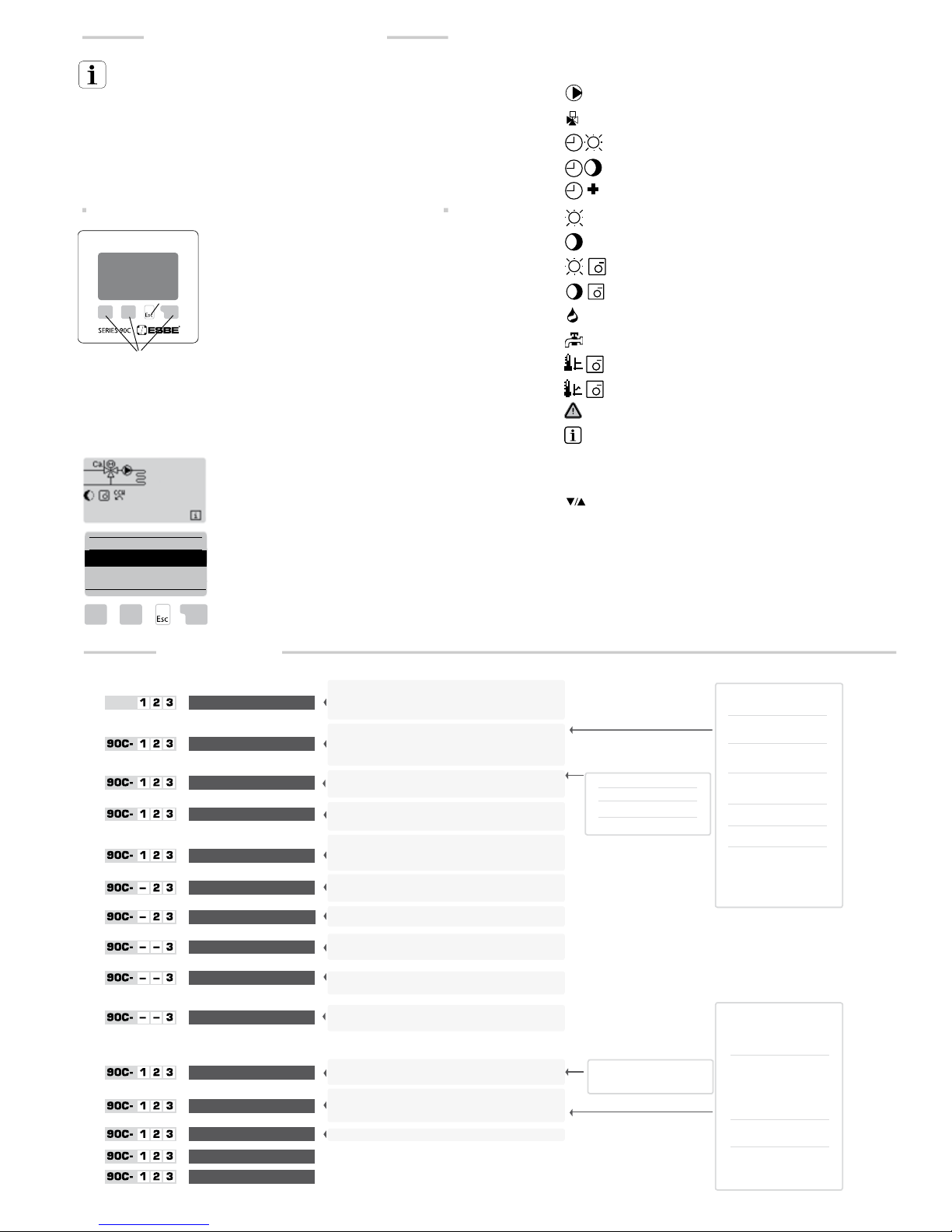
90C–1 90C–2 90C–3
1
Measurement 6
90C–1 90C–2 90C–3
2
Statistics 6
90C–1 90C–2 90C–3
3
Operating Times 6
90C–1 90C–2 90C–3
4
Operating Modes 6
90C–1 90C–2 90C–3
5
Setting Heating Circuit 7
Curve Examples 7
— 90C–2 90C–3
6
Heating Circuit 2 settings 7
— 90C–2 90C–3
7
DHW Settings 7
— — 90C–3
8
Energy transfer 8
— — 90C–3
9
Solar 8
— — 90C–3
10
Load Pump 8
90C–1 90C–2 90C–3
14
Protections 8
90C–1 90C–2 90C–3
15
Special Functions 8
90C–1 90C–2 90C–3
16
Menu Lock 9
90C–1 90C–2 90C–3
17
Service Data 9
90C–1 90C–2 90C–3
18
Language 9
Room Sensor 9
Hydronic variants - Application details 10-12
Hydronic variants - Application examples 13-14
CONTROLLER SERIES 90C

3
ABOUT THE CONTROLLER
The weather compensated integrated Heating Controller Ser ies 90C facilitates eff icient
use and function control of your heating system. The device is impressive mos t of all for its
functionality and simple, almost self-explanatory oper ation.
For each step in the input process the individual entr y keys are assigned to appropriate
functions and explained. The controller menu contains headwords for the measured values
and settings, as well as help texts or clearly-structured graphics.
Important characteristics of the series 90C:
- Depiction of graphics and texts in a lighted display
- Simple viewing of the current measurement values
- Statistics and monitoring of the system by means of statistical graphics, etc.
- Extensive setting menus with explanations
- Menu block can be activated to prevent unintentional setting changes
- Resetting to previously selected values or fact ory settings
- Automatic full calibration of valve positions at least once a day and after a power fail-
ure or disruption.
- Mixer valve operation range could be altered 90º/180º or 270º
DISPOSAL AND POLLUTANTS
The unit conforms to the European RoHS directive 2002/95/EC for the restriction of
the use of certain hazardous subs tances in electrical and electronic equipment.
The device must not be disposed of together with domes tic waste. This applies
in particular to the printed circuit card. Legislation may demand special handling
of certain components, or it may be desirable from an ecological point of view.
Local and currently valid legislation must be observed.
EC DECLARATION OF CONFORMITY
By affixing the CE mark to the unit the manufacturer declares that the series 90C
conforms to the following relevant safety regulations:
EC low voltage directive LVD 2006/95/EC
EC electromagnetic compatibility directive EMC 2004/108/EC
Conformity has been verified and the corresponding documentation and the EC declaration of conformity are kept on file by the manufacturer.
GENERAL INSTRUCTIONS It is essential that you read this!
These installation and operating instructions contain basic instructions and important
information regarding safet y, installation, commissioning, maintenance and the optimal
use of the unit. Therefore these instructions must be read completely and understood by
the installation technician/specialist and by the system user before installation, commissioning and operation of the unit.
The valid accident prevention regulations, the regulations of the local power utilit y, the
applicable ISO-EN standards and the inst allation and operating instruction of the additional
system components must also be observed. The controller does not under any circumstances replace any safety devices to be provided by the customer!
Installation, electrical connection, commissioning and maintenance of the unit may only be
carried out by specialists who possess the appropriate training.
For the user: Make sure that the specialist gives you detailed information on the function
and operation of the controller. Always keep these instructions in the vicinity of the controller.
EXPLANATION OF SYMBOLS
Failure to observe these instructions can result in danger to life from
electric voltage.
Failure to observe these instructions can result in destruction of the unit
or the system, or damage to the environment.
Information which is especially importation for the function and optimal
use of the unit and the system.
CHANGES TO THE UNIT
Changes to the unit can compromise the safet y and function of the unit or the
entire system.
- Changes, additions to or conversion of the unit are not permitted without written
permission from the manufacturer
- It is likewise forbidden to inst all additional components that have not been tested
together with the unit
- If it becomes clear that safe operation of the unit is no longer possible, for example
because of damage to the housing, then turn the controller off immediat ely
- Any parts of the unit or accessories that are not in perfect condition must be
excha nged immediately
- Use only original spare par ts and accessories from the manufacturer.
- Markings made on the unit at the factory must not be alter ed, removed or
made illegible
- Only the settings actually described in these instructions may be made on the controller
- If the plastic cover on the controller is opened the warranty expires unconditionally
WARRANTY AND LIABILITY
The controller has been manufactured and tested with regard to high quality and safety
requirements. The unit is subject to the statutory guarantee period of two years from
the date of sale. If the plastic cover on the controller is opened the warranty expires
unconditionally.
The warranty and liability shall not include, however, any injury to persons or material
damage that is attributable to one or more of the following causes:
- Failure to observe these installation and operating instructions
- Improper installation, commissioning, maintenance and operation
- Improperly executed r epairs
- Unauthorised structural changes to the unit
- Inst allation of additional components that have not been tested t ogether with the unit
- Any damage resulting from continued use of the unit despite an obvious defect
- Failure to use original spare parts and accessories
- Use of the device for other than its intended purpose
- Operation above or below the limit values listed in the specifications
zBasic unit: _______ Actuator controller with plastic housing, pr ewired for supply and sensors
Dimensions (HxWxT): _______________________________________ approx. 95x135x85 mm
Display: __________________________________________ fully graphical display 128x64 dots
Light emitting diode: ________________________________________ polychrome / multicolour
Operation: _____________________________________________________________ input keys
Power supply: __________________________________________ 230 ±10% V AC, 50/60 Hz
Power consumption: _____________________________________________________ ca 5.0 VA
Total switching capacity of the relay outputs 1-3: 2 (0,8) A 250 VAC (Circulation pump 185W)
Enclosure rating:________________________________________ IP 54 as per DIN 40050 CE
Protection class: _______________________________________________________________ II
Ambient temperature: ______________________________________________0° to 40°C max.
Ambient atmospheric humidity: _________________________________ max. 85% RH at 25°C
Actuator: _________________________________________________ Running time 120 s/90°
Torque: _________________________________________________________________ 15 Nm
Mixer valve operation range: ______________________________________ 90 / 180 or 270º
Sensors: _________________________________________ Temperature sensor type PT1000
Sensor cable: ________________________________________ 4x0.38mm2, max. length 30m
Temperature range: Flow pipe sensor CRS211 _______________________ 0 to +105°C
Outdoor sensor CRS214 _______________________ –50 to +70°C
Universal sensor CRS213 _______________________ 0 to +105°C
Room sensor CRS231 _________________________ +10 to +30°C
High temperature sensor CRS215 ______________ –50 to +550°C
Weight: __________________________________________________________________ 0.9 kg
Temperature resistance table for Pt1000 sensors:
T./°C
0 10 20 30 40 50 60 70 80 90 100
R./ Ω
1000 1039 1077 1116 1155 1194 1232 1270 1308 1347 1385
TECHNICAL DATA, SERIES 90C
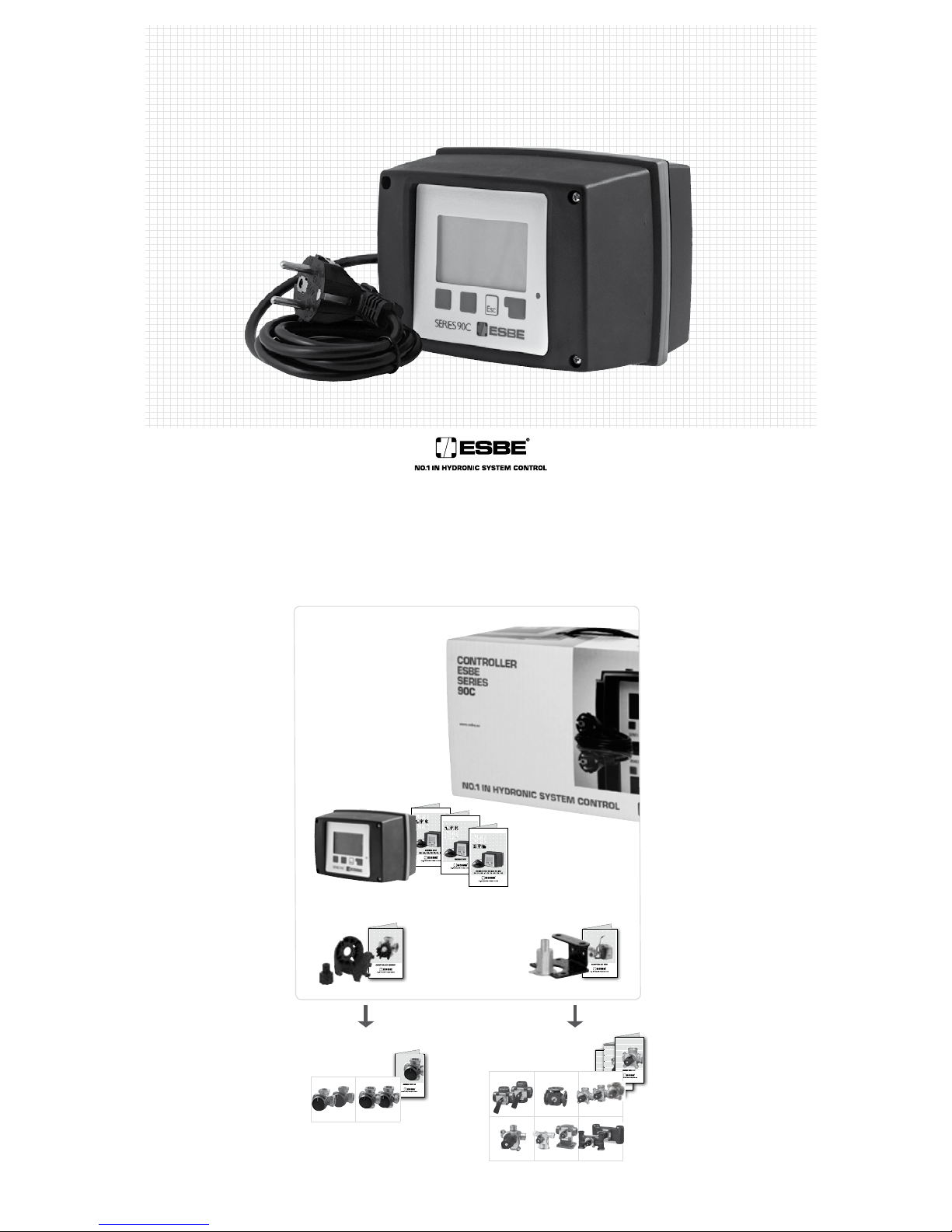
SCOPE OF SUPPLY
1. Optional room sensor can be connected
2. Power output box is prewired*
3. Functional test by means of status display with LED
4. 128x164 dot fully graphical display
5. Self-explanatory operation using softkey buttons
6. Outdoor sensor
7. 1.5 m power supply cable with plug is ready for connection
8. Sensor boxes are prewired*
9. Flow pipe sensor with 1.5 m cable is prewired
10. 20 m cable for sensors is optional
11. Universalsensor - ∅5mm, 1,5m*
12. Optional high temperature sensor can be connected
13.
Adaptor kit ESBE valves VRG, VRB
14.
Adaptor kit ESBE valves MG, G, 3F, BIV, 3H, 3HG
* Depending on version.
13
14
4
3
8
8
7
10
11
5
6
1
2
9
12
SAFETY INSTRUCTIONS
DANGER
CAUTION
ATTENTION
CONTROLLER SERIES 90C
4
The adaptor kits needed for ESBE mixing valves are supplied
with the controller. Connect
up
the actuator
controller and mixing valve as set out in the brief
description provided with each adaptor kit.
The controller can also be used for other makes of mixing valve using various adaptor
kits that can be ordered. Installation ins tructions will be enclosed with the adaptor kit
If desired the sensor cables can be extended to a maximum of 30m using a
cable with a cross-section of at least 0.38mm². Make sure that ther e is no
contact resistance!
Position the sensor precisely in the area to be measured! Only use immersion, pipe-mounted or flat-mounted sensor suitable for the specific area of
application with the appropriate permissible t emperature range.
The temperature sensor cables must be routed separately from mains
voltage cables, and must not, for example, be rout ed in the same cable duct!
FLOW PIPE SENSOR CRS211:
The sensor is prewired, and should be secured in a suitable position on the heating
circuit’s flow pipe using the pipe clip provided. To make sure that the correct temperature is registered, the sensor should be surrounded with pipe insulation.
OUTDOOR SENSOR CRS214:
Mount the outdoor sensor in a shady position out of the wind on the north side of the
building.
Connect the cable in the sensor box – polarity does not matter in this case. Depending
on the inertia of the heating system, set the back of the sensor box into the brickwork if
necessary in order to take the residual heat of the building into account.
ROOM SENSOR CRS231:
If a room sensor is required, it should be connected as follows:
Strip a maximum of 40 mm of insulation from a 4x0.38 mm² cable and insert the end
of the cable through the free lead-in on the under side of the actuator cover. Connect the
cable to the two free terminals in the black cover – polarity does not matter in this case.
UNIVERSAL SENSOR CRS213
Mount and secure the sensor in a suitable position according to the application. To
make sure the correct temperature is registered, the sensor should be surr ounded
with pipe insulation.
HIGH TEMPERATURE SENSOR CRS215:
Install the immersion sensor pocket in a suit able place for the application. Mount the
high temperature sensor inside the immersion sensor pocket.
Safety information: Power supply must be switched off completely before
work is started on the control and connected loads.
Warning: 230 VAC
If the circulation pump is to be operated via the contr oller, remove the three safety
terminals from the preconnected cable and connect the cable to the circulation pump
as follows:
Green/yellow: Earth PE
Blue: Neutral N
Brown/black/grey: Phase L
Please note: If the pump is not connected, the electrician should remove the cable.
Safety information: Power supply must be switched off completely before
work is started on the control and connected loads.
Warning: 230 VAC
Please note: The controller replaces in no way safety devices. Precautions such as
frost, scald and overpressure protection, etc., must be provided in the installation if
necessary.
The controller must only be installed by a qualified electrician in accordance with standards and/or local regulations.
The 90C controller should be wired up in the following order:
Plug the preconnected cable labelled “power supply” into a 230 V / 50 Hz socket
outlet with earthing contact.
Wiring:
Green/yellow: Earth PE
Blue: Neutral N
Brown: Phase L
COMMISSIONING HELP / SET-UP WIZARD
The first time the controller is turned on and af ter the language and time are set, a
query appears as to whether you want to parametrise the controller using the commissioning help or not. The commissioning help can also be terminated or called up again
at any time in the special functions menu 15.2. The commissioning help guides you through the necessary basic settings in the correct order, and provides brief descriptions
of each parameter in the display.
Pressing the „esc“ key takes you back to the previous value so you can look at the selected setting again or adjust it if desired. Pressing the „esc“ mor e than once takes you
back step by step to the selection mode, thus cancelling the commissioning help.
Observe the explanations for the the individual parameters on the following
pages, and check whether further settings are necessary for your application.
FREE COMMISSIONING
If you decide not to use the commissioning help, you should make the necessary settings in the following sequence:
- Menu 18. Language
- Menu 3. Time, date and operating times
- Menu 5 Settings for heat circuit, all settings
- Menu 14. Protective functions if necessary
- Menu 15. Special functions if necessary
- Menu 4.2 Operating mode „Manual“ should be used to test the switch outputs
with the consumers connected, and to check the sensor values for
plausibility. Then switch on automatic mode.
Observe the explanations for the the individual parameters on the following
pages, and check whether further settings are necessary for your application.
Do not open the unit until it has been disconnected!
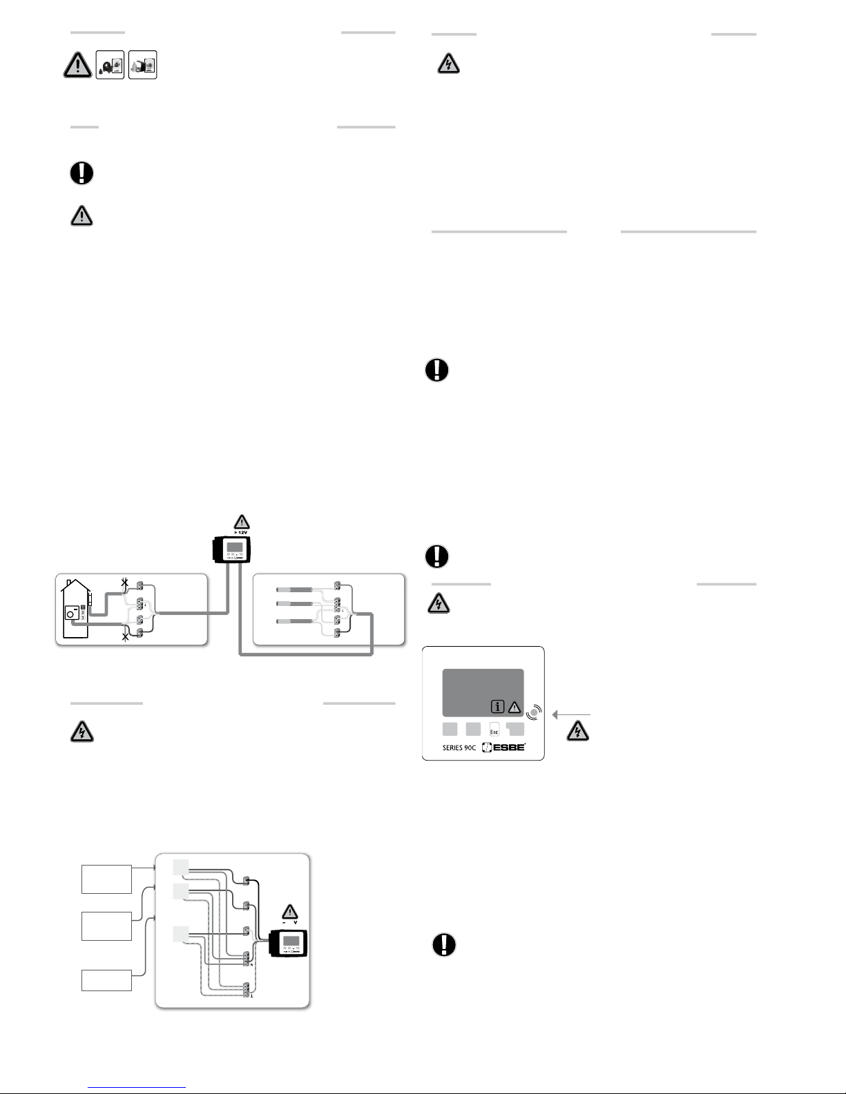
MALFUNCTIONS WITH ERROR MESSAGES
If the controller detects a malfunction, the red light
flashes and the warning symbol also appears in the
display. If the error is no longer present, the warning
symbol changes to an info symbol and the red light
no longer flashes. To obtain more detailed information on the error, press the key under the warning
or info symbol.
Do not try to deal with this yourself. Consult
a specialist in the event of an error!
MAINTENANCE
In the course of the general annual maintenance of your heating system you
should also have the functions of the controller checked by a specialist and
have the settings optimised if necessary.
Performing maintenance:
- Check the date and time (see menu 3.1)
- Assess/check plausibility of statistics (see menu 2)
- Check the error memory (see menu 2.6)
- Verify/check plausibility of the current measurement values (see menu 1)
- Check the switch outputs/consumers in manual mode (see menu 4.2)
- Poss. optimise the parameter settings
White
Yellow
Blue
MALFUNCTIONS / MAINTENANCE
Possible error/information messages:
Sensor x defective >
max. heat circuit
>
(Information only)
Restart
>
(Information only)
Notes for the specialist:
Means that either the sensor, the
sensor input at the controller or the
connecting cable is/was defective.
(Resistance table on page 3)
The maximum heat circuit temperature
set in menu 5.4 was exceeded.
Means that the controller was restarted, for example due to a power failure.
Check the date&time!
2
1
3
4
S3
S4
S7
Red
Red
White
Yellow
Blue
Orange
White
*
POWER SUPPLY - ELECTRICAL CONNECTION
INSTALLATION POWER OUTPUTS
SET-UP
Output 1Pumpcontrol
Output 2Extra function 2
Output 3Extra function 1
Phase L
Neutral N
Earth PE
Phase L
Neutral N
Earth PE
Phase L
Neutral N
~230
P1
P2
P3
*
FITTING THE ACTUATOR CONTROL
INSTALLATION OF TEMPERATURE SENSORS
ADAPTER KIT VRG801 ADAPTER KIT VRG900
* Depending on version.
* Depending on version.
Black
Brown
Grey
Blue
Yellow/Green
5
- The service values (see menu 17) include not only current measurement
values and operating states, but also all of the settings for the contr oller.
Write the service values down just once af ter commissioning has been successfully completed.
- In the event of uncertaint y as to the control response or malfunctions the service
values are a proven and successful method for remote diagnosis. Write the service values down (see menu 17) at the time that the suspected malfunction occur s. Send the
service value table by fax or e-mail with a brief description of the error to the specialist
or manufacturer.
- To protect against loss of data, record any statistics and data that are particularly important to you (see menu 2) at regular intervals.
DISPLAY AND INPUT
The display (1), with its extensive text and graphics
mode, is almost self-explanatory, allowing easy
operation of the controller.
The LED (2) lights up green when a relay is switched
on.
The LED (2) lights up red when operating mode „Off“
is set.
The LED (2) flashes slowly red in the operating
mode „Manual“.
The LED (2) flashes quickly red when an error is
present.
Entries are made using four keys (3+4), to which dif ferent functions are assigned depending on the situation. The „esc“ key (3) is used to cancel an entry or to exit a menu.
If applicable there will be a request for confirmation as to whether the changes which
have been made should be saved.
The function of each of the other three keys (4) is shown in the display line directly
above the keys; the right-hand key generally has a confirmation and selection function.
MENU SEQUENCE
The overview mode appears when no key has been
pressed for 2 minutes, or when the main menu is
exited by pressing „esc“.
The menu is closed by pressing “esc” or selecting
“Exit measurements”.
Pressing a key in graphics or overview mode takes you
directly to the main menu. The following menu items
are then available for selection there.
Examples of display symbols:
Heating circuit pump (rotates when active)
Heating circuit mixer (black when active)
Day mode (Time progr.)
Night mode (Time progr.)
Comfort mode (Time progr.)
Day mode
Night mode
Day mode due to Room sensor
Night mode due to Room sensor
Heat activated (Info only)
Domestic hot water activated (Info only)
Reference value mode
Reference value 14 day
Warning / Error message
New information available
Examples of key functions:
+/- = enlarge/shrink values
= scroll menu down/up
yes/no = approve/reject
Info = additional information
Back = to previous scr een
ok = confirm selection
Confirm = confirm setting
Out door 0°C
Flow 27°C
Target fl. 27°C
Room 21°C
Exit main menu
2. Statistics
▲ ▼
OK
1. Measurements
3.1 Time and date
3.2 Daylight Saving
3.3 Heating circuit day
3.4 Heating comfort
3.5 Hot water enable
3.6 Hot water AL
3. Times
2.1 Today
2.2 28 days
2.3 Outdoor 8760h
2.4 Flow 8760h
2.5 Op.hours HC
2.6 Op.hours DHW
2.7 Op.hours HC2
2.8 Op.hours Heat
2.9 Error messages
2.10 Reset/Clear
2. Statistics
1. Measurement
1.1 Outdoor
1.2 Flow
1.3 Flow 2
1.4 Sensor 4
1.5 Room
1.6 Room sensor
1.7 RC switch
1.8 Target flow
1.9 Target flow 2
5. HC Settings
5.1 S/W day
5.2 S/W night
5.3 Curve
5.4 Day correct
5.5 Night correct
5.6 Comfort temp. boost
5.7 Reference/actual -
5.8 Reference/actual +
6. HC 2 Settings
6.1 S/W day
6.2 S/W night
6.3 Curve
6.4 Day correct
6.5 Night correct
6.6 Comfort temp. boost
14.5.1 AL function
14.5.2 AL Tset
14.5.3 AL Interval
14.5.4 AL heat
8. Energy transfer
8.1 Pump start temp.
8.2 Hysteresis
8.3 Target temp.
9. Solar
9.1 Hysteresis
9.2 Pump stop temp.
10. Load pump
10.1 Pump st art temp
10.2 Hysteresis
10.3 Min. running time
17. Service Data
18. Language
14. Protections
14.1 Frost protection
14.2 Min. flow
14.3 Max. flow
14.4 Max flow 2
14.5 Anti-legionella
16. Menu Lock
16.1 Menu Lock
7. DHW Settings
7.1 Hotwater min.
7.2 DHW target
7.3 DHW hysteresis
4. Operating mode
4.1 Heating circ.
4.2 Manual
4.3 Heat circuit reference
4.4 14 day reference
4.5 Domestic hot water
2.3.1 Current Year
2.3.2 Previous Year
2.3.3 2 years ago
2.4.1 Current Year
2.4.2 Previous Year
2.4.3 2 years ago
2.5.1 Op.hours HC
2.5.2 Since
2.7.1 Op.hours HC 2
2.7.2 Since
2.8.1 Op.hours HC heat
2.8.2 Since
2.6.1 Op.hours DHW
2.6.2 Since
2.10.1 Today
2.10.2 28 days
2.10.3 Outdoor 8760h
2.10.4 Flow 8760h
2.10.5 Operating Hours
2.10.6 Error messages
2.10.7 All statistics
3.3.1.Mo. - 3.3.7 Su
3.4.1.Mo. - 3.4.7 Su
3.5.1.Mo. - 3.5.7 Su
3.6.1.Mo. - 3.6.7 Su
15.6.1 Room sensor
15.6.2 Room ref. day
15.6.3 Room ref. night
15.5.1 Valve type
15.5.2 Min angle
15.5.3 Max angle
15.5.4 Direction
15.5.5 Turn time
15.5.6 Pause factor
15.5.7 Increase
15.5.8 Calibration
15.1.1 Outdoor
15.1.2 Flow
15.1.3 Domestic hot water
15.1.4 Sensor 4
15.1.5 Room
15.1.6 Room sensor
15.7.1 Extra function 1
15.7.2 Extra function 2
15.7.3 Valve position
15.7.4 Heat delay
15.7.5 Valve delay
15.1 Sensor calibration
15.2 Comissioning
15.3 Factory settings
15.4 Expansions (n/a)
15.5 Mixer
15.6 Room sensor
15.7 System
15. Special functions
MENU STRUCTURE
USEFUL NOTES / TIPS AND TRICKS
MENU NAVIGATION – SETTING AND CHECKING PARAMETERS
(2)
(1)
(3)
(4)
MENU
AVAILABLE IN
version
90C-
 Loading...