


GB
Aristo
U8
2
Instruction manual
Valid from program version 1.100460 896 174 GB 20121019

1 SAFETY 5...........................................................
2 INTRODUCTION 6...................................................
2.1 Control panel Aristo U82 6....................................................
2.1.1 Keys and knobs 6......................................................
2.2 Location 7..................................................................
2.3 USB connection 7...........................................................
2.3.1 Insert USB memory 8...................................................
2.4 First step – choice of language 8..............................................
2.5 Display 9...................................................................
2.5.1 Symbols in the display 10.................................................
2.6 General information about settings 11...........................................
2.6.1 Setting of numerical values 11.............................................
2.6.2 Setting with given alternatives 11..........................................
2.6.3 Settings ON/OFF 11.....................................................
2.6.4 QUIT and ENTER 11.....................................................
3 MENUS 12...........................................................
3.1 Main menu 12...............................................................
3.1.1 Configuration menu 13...................................................
3.1.2 Tools menu 13..........................................................
3.1.3 Weld data setting menu 14................................................
3.1.4 Measure 14.............................................................
3.1.5 Weld data memory meny 15..............................................
3.1.6 Fast mode menu 15......................................................
4 MIG/MAG WELDING 16................................................
4.1 Settings in the weld data setting menu 17........................................
4.1.1 MIG/MAG welding with short-/sprayarc. 17..................................
4.1.2 MIG/MAG welding with pulsing 18.........................................
4.1.3 MIG/MAG welding with SuperPulse, primary/secondary, short-/sprayarc/pulsing . . .
4.2 Function explanations for settings 20............................................
4.2.1 QSet 25................................................................
4.2.2 Synergy group 25........................................................
4.3 SuperPulse 26...............................................................
4.3.1 Wire and gas combinations 27.............................................
4.3.2 Different pulsing methods 27..............................................
4.3.3 Wire feed unit 27........................................................
19
5 MMA WELDING 29....................................................
5.1 MMA welding DC 29..........................................................
5.2 MMA welding AC 30..........................................................
5.3 Function explanations for settings 30............................................
6 TIG WELDING 31.....................................................
6.1 Settings in the weld data setting menu 31........................................
6.1.1 TIG welding without pulsing DC 31.........................................
6.1.2 TIG welding with pulsing DC 32............................................
6.1.3 TIG welding without pulsing AC 32.........................................
6.2 Function explanations for settings 33............................................
6.3 Other function explanations 37.................................................
Rights reserved to alter specifications without notice.
TOCe
- 2 -

7 ARC AIR GOUGING 38................................................
7.1 Settings in the weld data setting menu 38........................................
7.2 Function explanations 38......................................................
8 MEMORY MANAGEMENT 39...........................................
8.1 Control panel working method 39...............................................
8.2 Store 40....................................................................
8.3 Recall 41....................................................................
8.4 Delete 42...................................................................
8.5 Copy 43.....................................................................
8.6 Edit 44......................................................................
8.7 Name 46....................................................................
9 CONFIGURATION MENU 47...........................................
9.1 Code lock 47...............................................................
9.1.1 Lock code status 48......................................................
9.1.2 Specify/edit lock code 48.................................................
9.2 Remote controls 49...........................................................
9.2.1 Forget override 49.......................................................
9.2.2 Configuration for digital remote control unit 49...............................
9.2.3 Configuration for analogue remote control unit 50............................
9.2.4 Scale on inputs 50.......................................................
9.3 MIG/MAG defaults 51.........................................................
9.3.1 Gun trigger mode (2-stroke/4-stroke) 51....................................
9.3.2 4-stroke configuration 52.................................................
9.3.3 Soft key configuration 53.................................................
9.3.4 Voltage measurement in pulsing 54........................................
9.3.5 AVC feeder 55..........................................................
9.3.6 Release pulse 55........................................................
9.4 MMA defaults 55.............................................................
9.5 Fast mode soft keys 55.......................................................
9.6 Double start sources 56.......................................................
9.7 Panel remote enable 56.......................................................
9.8 WF supervision 56...........................................................
9.9 Auto save mode 56...........................................................
9.10 Trigger weld data switch 56....................................................
9.11 Multiple wire feeders 58.......................................................
9.12 Quality functions 59..........................................................
9.13 Maintenance 59..............................................................
9.14 Unit of length 60.............................................................
9.15 Measure value frequency 60...................................................
9.16 Register key 60..............................................................
Rights reserved to alter specifications without notice.
TOCe
- 3 -

10 TOOLS 61............................................................
10.1 Error log 61..................................................................
10.1.1 Units 62................................................................
10.1.2 Error code descriptions 62................................................
10.2 Export/Import 65.............................................................
10.3 File manager 66..............................................................
10.3.1 Delete a file/folder 67.....................................................
10.3.2 Rename a file/folder 67...................................................
10.3.3 Create new folder 67.....................................................
10.3.4 Copy and paste files 68...................................................
10.4 Edit setting limits 68..........................................................
10.5 Edit measure limits 69........................................................
10.6 Production statistics 70.......................................................
10.7 Quality functions 71..........................................................
10.7.1 Store quality data 72.....................................................
10.8 User defined synergic data 73..................................................
10.8.1 Specify voltage/wire co-ordinates 73.......................................
10.8.2 Specify valid wire/gas combination 74......................................
10.8.3 Create your own wire/gas alternative 75....................................
10.9 Calendar 76.................................................................
10.10 User accounts 76............................................................
10.11 Unit information 77...........................................................
11 ORDERING SPARE PARTS 78.........................................
MENU STRUCTURE 79...................................................
WIRE AND GAS DIMENSIONS 85.........................................
ORDER NUMBER 90.....................................................
ACCESSORIES 91.......................................................
Rights reserved to alter specifications without notice.
TOCe
- 4 -
GB
1 SAFETY
NOTE! This unit is tested by ESAB in a general set-up. The repsonsibility for safety
and function, of the specific set-up, lies with the integrator.
Users of ESAB equipment have the ultimate responsibility for ensuring that anyone who works on or
near the equipment observes all the relevant safety precautions. Safety precautions must meet the
requirements that apply to this type of equipment. The following recommendations should be ob
served in addition to the standard regulations that apply to the workplace.
All work must be carried out by trained personnel well-acquainted with the operation of the equip
ment. Incorrect operation of the equipment may lead to hazardous situations which can result in in
jury to the operator and damage to the equipment.
1. Anyone who uses the equipment must be familiar with:
its operation
location of emergency stops
its function
relevant safety precautions
welding and cutting
2. The operator must ensure that:
no unauthorised person is stationed within the working area of the equipment when it is star
ted up.
no-one is unprotected when the arc is struck
3. The workplace must:
be suitable for the purpose
be free from drafts
4. Personal safety equipment
Always wear recommended personal safety equipment, such as safety glasses, flame-proof
clothing, safety gloves.
Do not wear loose-fitting items, such as scarves, bracelets, rings, etc., which could become
trapped or cause burns.
5. General precautions
Make sure the return cable is connected securely.
Work on high voltage equipment may only be carried out by a qualified electrician.
Appropriate fire extinquishing equipment must be clearly marked and close at hand.
Lubrication and maintenance must not be carried out on the equipment during operation.
Dispose of electronic equipment at the recycling facility!
In observance of European Directive 2002/96/EC on Waste Electrical and Electronic
Equipment and its implementation in accordance with national law, electrical and/or
electronic equipment that has reached the end of its life must be disposed of at a
recycling facility.
As the person responsible for the equipment, it is your responsibility to obtain
information on approved collection stations.
For further information contact the nearest ESAB dealer.
bi23e
- 5 -
© ESAB AB 2012

GB
2 INTRODUCTION
To benefit as much as possible from your welding equipment, we recommend that
you read this instruction manual.
For general information about operation, see the instruction manuals for the power
source and the wire feed unit.
The text presented in the display is available in the following languages:
English, Swedish, Finnish, Norwegian, Danish, German, French, Italian, Dutch,
Spanish, Portuguese, Hungarian, Polish, American, Czech, Chinese and Turkish.
NOTE! Differences in the panel function may occur, depending on in which product it
is installed.
2.1 Control panel Aristo U8
2
The control panel is supplied with a mounting bracket with screws and an English
instruction manual. A 1.2 m cable is mounted on to the panel. A USB memory and
an extension cable are available as accessories, see page 91.
Instruction manuals in other languages can be downloaded from the website,
www.esab.com.
Place for USB memory
Knob for moving cursor
Display
Soft keys
Menu
Enter
Knob for increasing or
decreasing set values and
setting the voltage, #
Knob for increasing or
decreasing set values and setting the wire feed speed, *
2.1.1 Keys and knobs
Soft keys (4)
The five keys in a row under the display have
varying functions. These are “soft” keys, i.e. they
can have different functions depending on which
menu you are currently working in. The current
function for these keys can be seen from the text
in the bottom row of the display.
When the function is active, this is indicated by the
key turning white:
- 6 -
bi23e
© ESAB AB 2012
GB
Menu key (5)
Using the MENU key always takes you back to the main menu:
MIG/MAG
PROCESS MIG/MAG
METHOD SHORT/SPRAY
QSET OFF
SYNERGY GROUP STANDARD
WIRE TYPE Fe
SHIELDING GAS Ar+8%CO2
WIRE DIAMETER 1.2 mm
CONFIGURATION"
TOOLS
FAST
SET MEASURE MEMORY
MODE
Enter key (6)
Using the ENTER key confirms a selection.
Cursor knob (2)
Using the left-hand knob moves the cursor to different rows in the display.
Plus/minus knobs (7, 8)
The right-hand knobs increase or decrease the value of a setting. To the side of the
knobs there is a symbol, a square or a star . Most numerical settings can be
adjusted with either knob, although certain settings have to be made with a particular
knob.
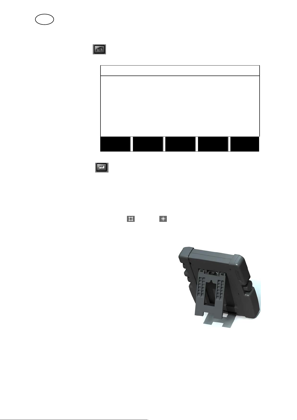
2.2 Location
On the reverse of the control panel there is a
fold-out stand that enables you to put the panel
down and still view the display in an upright position.
The stand also acts as a mounting device, enabling
the control panel to be hung on the wire feed unit.
2.3 USB connection
External USB memories can be used to transfer programs
to and from the control panel. See more in chapter 10.2.
The files that are produced in the control panel are stored as xml files. The USB
memory must be formatted as FAT 32 in order to work.
During normal use there is no risk of “viruses” being able to infect the equipment. To
eliminate this risk entirely, we recommend that the memory that is used together with
this equipment not be used for any other purpose.
Certain USB memories may not work with this equipment. We recommend using
USB memories from a reputable supplier. ESAB assumes no responsibility for any
damage caused as a consequence of the incorrect use of a USB memory.
bi23e
- 7 -
© ESAB AB 2012
GB
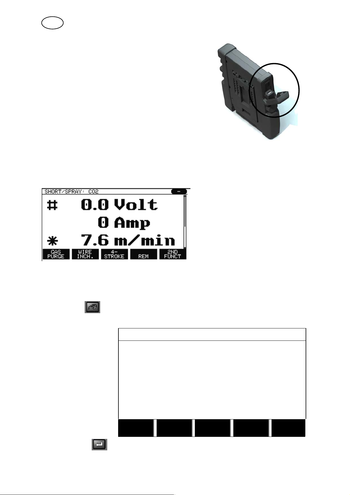
2.3.1 Insert USB memory
Proceed as follows:
Turn off the power source's main switch.
Open the cover on the left-hand end of the control
panel.
Insert the USB memory in the USB connector.
Close the cover.
Turn on the power source's main switch.
2.4 First step – choice of language
This menu appears in the display the first time you start up the equipment.
The control panel is set to English on delivery. To select your language, proceed as
follows.
Press MENU to come to the main menu.
MIG/MAG
Using the left-hand
knob, position the
cursor on the CONFIG
URATION row
PROCESS MIG/MAG
METHOD SHORT/SPRAY
QSET OFF
SYNERGY GROUP STANDARD
WIRE TYPE Fe
SHIELDING GAS Ar+8%CO2
WIRE DIAMETER 1.2 mm
CONFIGURATION "
TOOLS
FAST
SET MEASURE MEMORY
MODE
Press ENTER .
bi23e
- 8 -
© ESAB AB 2012
GB
CONFIGURATION
Position the cursor on
the LANGUAGE row.
Press ENTER to bring
up a list of the
languages that are
available in the control
panel.
LANGUAGE ENGLISH
CODE LOCK
REMOTE CONTROLS
MIG/MAG DEFAULTS
MMA DEFAULTS
FAST MODE SOFT KEYS
DOUBLE START SOURCES OFF
PANEL REMOTE ENABLE OFF
WF SUPERVISION ON
AUTO SAVE MODE OFF
TRIGGER WELDDATA SWITCH
Position the cursor on the row for your language and
press ENTER.
NORSK
POLSKI
PORTUGUES
SUOMI
SVENSKA
CHINESE
QUIT
|
|
|
2.5 Display
MIG/MAG
PROCESS MIG/MAG
METHOD SHORT/SPRAY
QSET OFF
SYNERGY GROUP STANDARD
WIRE TYPE Fe
SHIELDING GAS Ar+8%CO2
WIRE DIAMETER 1.2 mm
CONFIGURATION "
TOOLS
FAST
SET MEASURE MEMORY
The cursor
The control panel's cursor is presented as a shaded field around the text, with the
selected text turning white. The selection is displayed in the instruction manual with
bold text.
MODE
bi23e
- 9 -
© ESAB AB 2012
GB
Arrows and scroll bars
Where there is more information behind a row, this is indicated with a black arrow
behind the text. A scroll bar is presented to the right of the display if there are more
rows in the list:
Text boxes
At the bottom of the display are five boxes containing text that describes the current
function of the five keys directly below the boxes.
Energy saving mode
To increase the life of the background lighting, it is switched off after three minutes of
no activity.
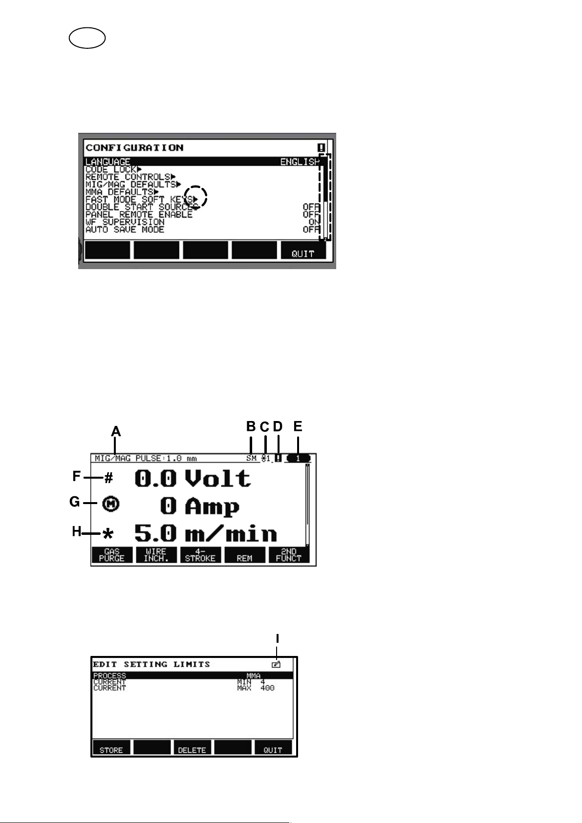
2.5.1 Symbols in the display
A The selected weld data set
B S = Setting limit activated
M = Measure limit activated
C The selected wire feed unit
D A fault has occurred. See chapter
15
E Recalled memory position number
F Select the plus/minus knob marked
with # to increase or decrease a
parameter value.
G Measured motor current
H Select the plus/minus knob marked
with * to increase or decrease a
parameter value.
bi23e
I Editing mode, editing memory
position
- 10 -
© ESAB AB 2012

GB
2.6 General information about settings
There are three main types of setting:
Setting of numerical values
Setting with given alternatives
Setting of ON/OFF mode
2.6.1 Setting of numerical values
When setting a numerical value, one of the two plus/minus knobs is used to increase
or decrease a given value. A number of values can also be altered from the remote
control unit.
2.6.2 Setting with given alternatives
Some settings are made by selecting an alternative from a list.
Such a list might look like this:
MIG/MAG
MMA
TIG
GOUGING
Here the cursor is placed on the row for MIG/MAG. By pressing ENTER in this
position, the MIG/MAG alternative is selected. If you want to choose another
alternative instead, position the cursor on the correct row by stepping up or down
with the left knob. Then press ENTER . If you want to exit the list without making a
selection, press QUIT.
2.6.3 Settings ON/OFF
For some functions, it is possible to set the values ON and OFF. The synergy
function during MIG/MAG and MMA welding is an example of such a function. The
ON or OFF settings can be selected from a list of alternatives as described above.
2.6.4 QUIT and ENTER
The “soft” key farthest to the right is used primarily for QUIT, although it is
occasionally used for other functions.
Pressing QUIT entails moving back to the previous menu or screen.
The key is called ENTER in this manual.
Pressing ENTER entails the execution of a selected choice in a menu or a list.
bi23e
- 11 -
© ESAB AB 2012

GB
3 MENUS
The control panel uses several different menus. The menus are the Main,
Configuration, Tools, Weld data setting, Measure, Weld data memory and Fast
mode menus. The menu structures are displayed from the page 79. During start-up,
a start-up screen containing information about the current program version is also
displayed briefly.
Start-up screen
3.1 Main menu
In the MAIN MENU,
you can change
welding process,
welding method, wire
type, etc.
From this menu you
can proceed to all other
sub-menus.
MIG/MAG
PROCESS MIG/MAG
METHOD SHORT/SPRAY
QSET OFF
SYNERGY GROUP STANDARD
WIRE TYPE Fe
SHIELDING GAS Ar+8%CO2
WIRE DIAMETER 1.2 mm
CONFIGURATION "
TOOLS
FAST
SET MEASURE MEMORY
MODE
bi23e
- 12 -
© ESAB AB 2012

GB
3.1.1 Configuration menu
CONFIGURATION
In the CONFIGURA
TION menu you can
change language, alter
other basic settings,
unit of measurement,
etc.
3.1.2 Tools menu
In the TOOLS menu
you can transfer files,
view quality and
production statistics,
error logs, etc.
LANGUAGE ENGLISH
CODE LOCK
REMOTE CONTROLS
MIG/MAG DEFAULTS
MMA DEFAULTS
FAST MODE SOFT KEYS
DOUBLE START SOURCES OFF
PANEL REMOTE ENABLE OFF
WF SUPERVISION ON
AUTO SAVE MODE OFF
TRIGGER WELD DATA SWITCH
QUIT
TOOLS
ERROR LOG
EXPORT/IMPORT
FILE MANAGER
SETTING LIMIT EDITOR
MEASURE LIMIT EDITOR
PRODUCTION STATISTICS
QUALITY FUNCTIONS
USER DEFINED SYNERGIC DATA
CALENDAR
USER ACCOUNTS
bi23e
QUIT
- 13 -
© ESAB AB 2012

GB
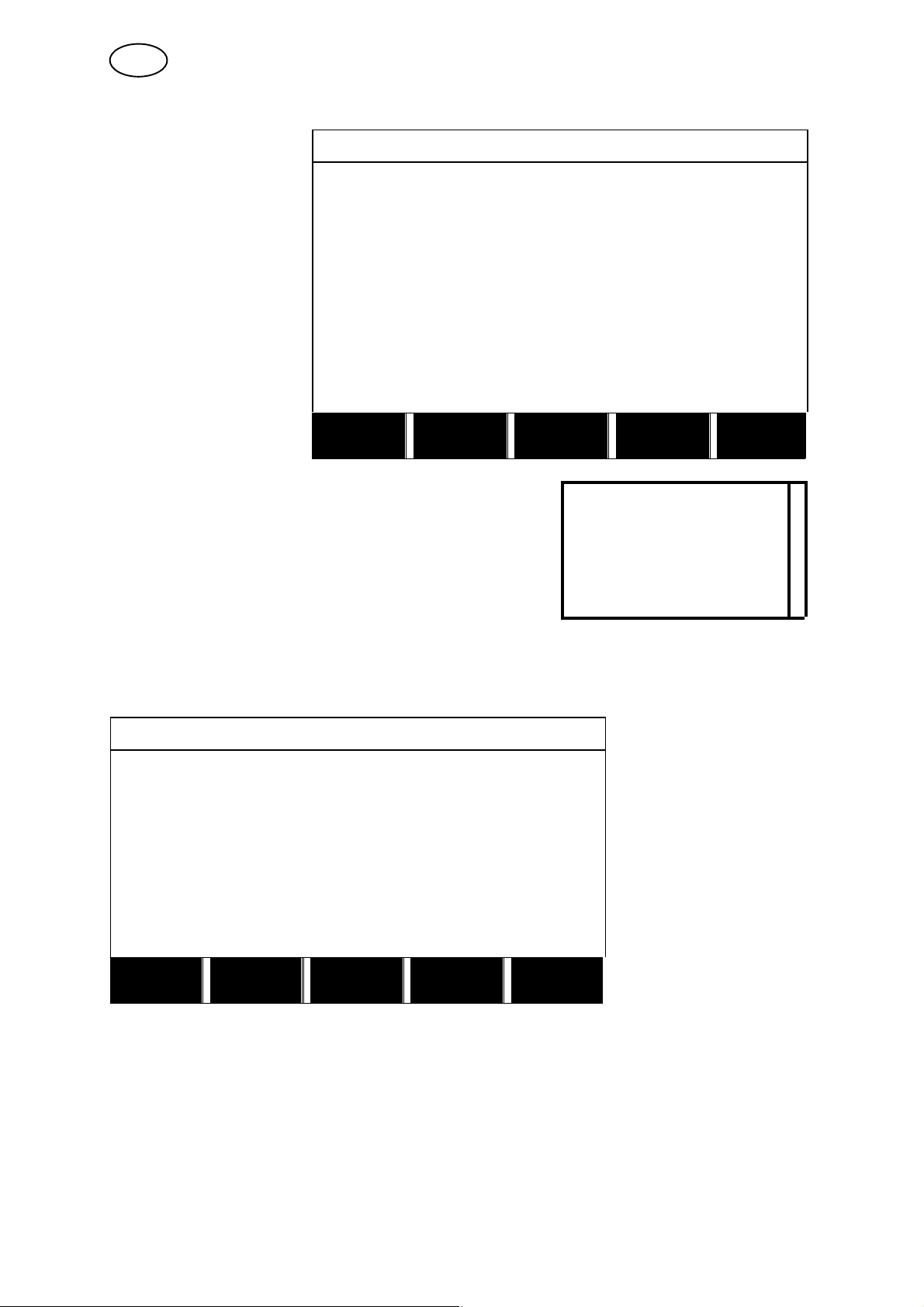
3.1.3 Weld data setting menu
WELD DATA SETTING
In the WELD DATA
SETTING menu you
can alter various
welding parameters.
The menu has different
appearances depend
ing on which welding
process is selected.
The example shows
MIG/MAG welding with
short-/sprayarc.
3.1.4 Measure
In MEASURE, you can
view measured values
for various welding
parameters while
welding is in progress.
VOLTAGE 28.2 (+3.5) V
WIRE SPEED 6.0 M/MIN
INDUCTANCE 80%
SYNERGIC MODE ON
START DATA
STOP DATA
SETTING LIMITS
MEASURE LIMITS
SPOT WELDING
EDIT DESCRIPTION
CRATER
FILL
SHORT/SPRAY. Fe, CO2, 1.2 mm
HOT
START
4-
STROKE QUIT
# 0.0 Volt
0 Amp
* 6.0 m/min
GAS
PURGE
You can change the value of certain parameters in the Measure screen. Which
parameters these are depends on which welding process is set. The parameter
values that can be adjusted are always marked with # or *.
The measured values remain in the display even after welding has been completed.
You can move to different menus without losing the measurement values. If the set
value is altered when welding is not in progress, the measurement value is changed
to zero in order to avoid confusion.
TIP:
When pulsing, you can select whether the voltage value is to be displayed as an
average value or a peak value. This setting can be adjusted under MIG/MAG
defaults, see chapter 9.3.
WIRE
INCH
4-
STROKE
REM
2ND
FUNCT
bi23e
- 14 -
© ESAB AB 2012

GB
3.1.5 Weld data memory meny
WELD DATA MEMORY
In the WELD DATA
MEMORY menu you
can store, recall, delete
and copy various set
weld data. The weld
data sets can be stored
in 255 different memory
positions.
For further information, see the chapter 8 “Memory management”.
3.1.6 Fast mode menu
In the FAST MODE
menu, you can “link”
soft keys to weld data
memory positions.
These settings are
carried out in the
Configuration menu.
The number of the
selected memory
position is displayed in
the top right corner.
1 2 3 4 5 6 7 -
2ND
STORE
SHORT/SPRAY. Fe, CO2, 1.2 mm 7
FUNCT QUIT
# 28.5 Volt
0 Amp
* 6.0 m/min
WELD
DATA 1
For further information, see the chapter 9.5 “Fast mode soft keys”.
bi23e
WELD
DATA 2
- 15 -
WELD
DATA 3
WELD
DATA 4
2ND
FUNCT
© ESAB AB 2012
GB
4 MIG/MAG WELDING
Main menu Process
MIG/MAG welding melts a continuously supplied filler wire, with the weld pool being
protected by shielding gas.
Pulsing is used to influence the transfer of the droplets from the arc so that it
remains stable and spatter-free, even with low weld data.
The table on page 85 shows the wire diameters that can be selected for MIG/MAG
welding with SHORT-/SPRAYARC.
The table on page 85 shows the wire diameters that can be selected for MIG/MAG
welding with PULSING.
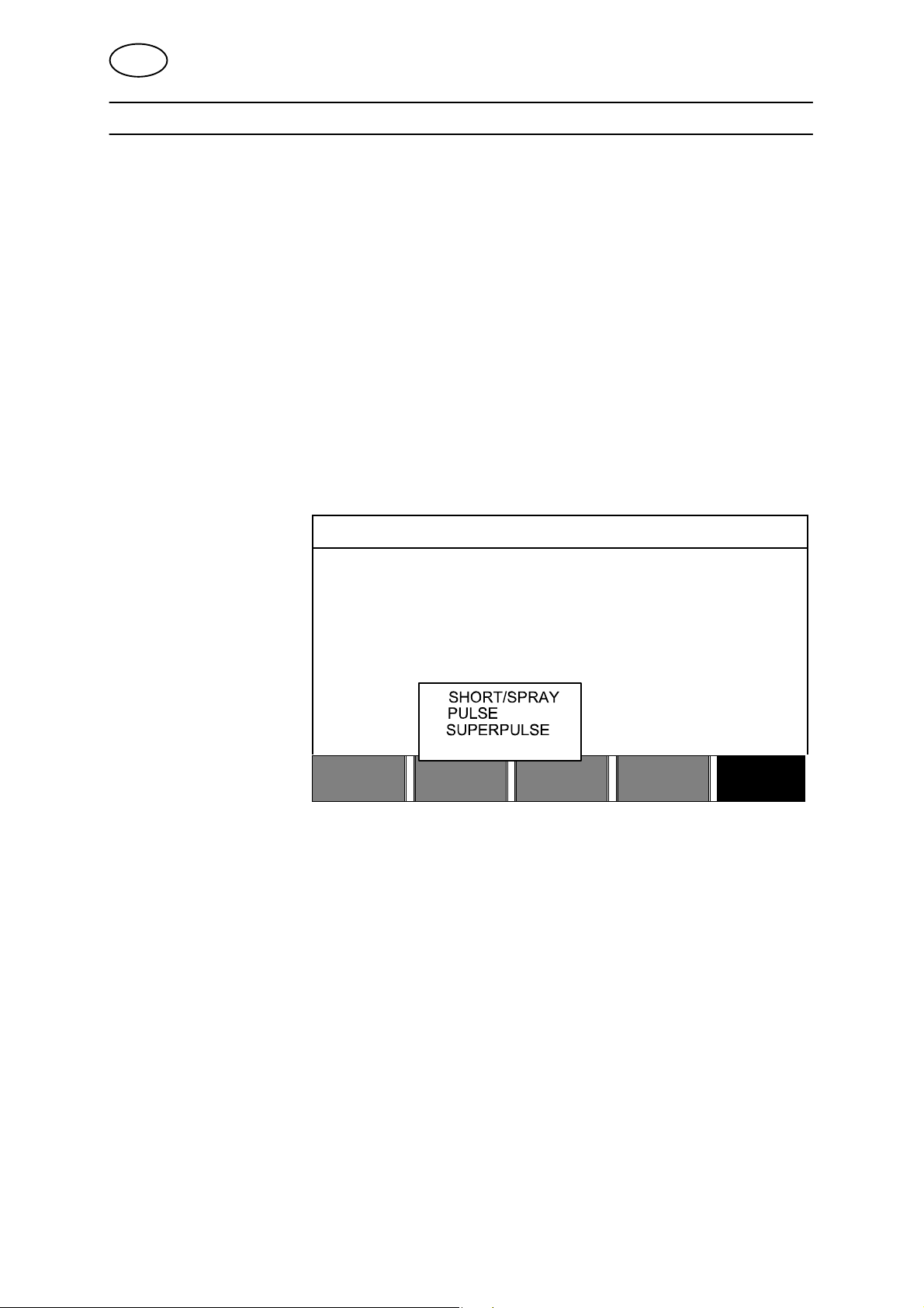
When the MIG/MAG process is selected, you can choose between four methods by
selecting Method with the left-hand knob and then pressing ENTER. Choose
between short-/sprayarc, puls or superpulse and then press ENTER again.
MIG/MAG
PROCESS MIG/MAG
METHOD SHORT/SPRAY
QSET OFF
SYNERGY GROUP STANDARD
WIRE TYPE Fe
SHIELDING GAS CO2
WIRE DIAMETER 1.2 mm
CONFIGURATION MIG/MAG
TOOLS" MIG/MAG
QUIT
bi23e
- 16 -
© ESAB AB 2012

GB
4.1 Settings in the weld data setting menu
4.1.1 MIG/MAG welding with short-/sprayarc.
Settings Setting range In steps of Synergy
depend
ent
Voltage 8 - 60 V 0.25 V
(displayed with
one decimal)
Wire feed speed** 0.8 - 30.0 m/min 0.1 m/min x
Inductance 0 - 100% 1% x x
Regulator type 1 - 12 1 x -
Synergy* OFF or ON - - -
Gas pre-flow 0.1 - 25 s 0.1 s x
Creep start OFF or ON - x
“Hot start” OFF or ON - x
“Hot start” time 0 - 10 s 0.1 s x
“Hot start” wire feed Complete wire feed range 0.1 m/min x
“Touch sense” 10 - 16 A
Soft start OFF or ON - x
Crater filling OFF or ON - x
Crater filling time 0 - 10 s 0.1 s x
Final crater filling wire feed 1.5 m/min at current wire feed
speed
Final crater filling voltage 8 - 24.7 V x
“Release pulse”*** OFF or ON
Burnback time 0 - 1 s 0.01 s x
Termination Final pulse or SCT - x
Gas post-flow 0.1 - 25 s 0.1 s x
Setting limits 1 - 50 - - -
Measure limits 1 - 50 - - -
Spot welding **** OFF or ON - x
Spot welding time 0 - 25 s 0.1 s x
0.1 m/min x
x x
Ad
justable
in syn
ergy
*) The synergic line on delivery: solid wire (Fe), shielding gas CO
**)The setting range is dependent on the wire feed unit used.
***) Adjusted in the configuration menu MIG/MAG defaults.
****) It is not possible to select spot welding (ON) if gun trigger mode is 4-stroke.
- 17 -
bi23e
with wire 1.2 mm.
2
© ESAB AB 2012

GB
4.1.2 MIG/MAG welding with pulsing
Settings Setting range In steps of Synergy
depend
ent
Voltage 10 - 50 V 0.25 V
(displayed with
one decimal)
Wire feed speed* 0.8 - 30.0 m/min 0.1 m/min x
Pulse current** 100 - 650 A 4 A x
Pulse time 1.7 - 25.5 ms 0.1 ms x
Pulse frequency 16 - 312 Hz 2 Hz x
Background current 4 - 300 A 1 A x
Slope 1 - 9 1 x
Synergy*** OFF or ON - - Ka 0 - 100% 1% x
Ki 0 - 100% 1% x
Gas pre-flow 0.1 - 25 s 0.1 s x
Creep start OFF or ON - x
Soft start OFF or ON - x
“Hot start” OFF or ON - x
“Hot start” time 0 - 10 s 0.1 s x
“Hot start” wire feed Complete wire feed range 0.1 m/min x
“Touch sense” 10 - 16 A
Crater filling
(pulsed/not pulsed)
Crater filling time 0 - 10 s 0.1 s x
Final crater filling wire feed 1.5 m/min at current wire feed
Final crater filling voltage 8 - 33.2 V x
Final pulse current 100 - max A x
Final background current 12 - 50 A x
Final frequency 20 - 270 Hz x
“Release pulse”**** OFF or ON
Burnback time 0 - 1 s 0.01 s x
Termination Final pulse or SCT - x
Gas post-flow 0.1 - 25 s 0.1 s x
Setting limits 1 - 50 - - Measure limits 1 - 50 - - Spot welding ***** OFF or ON - x
Spot welding time 0 - 25 s 0.1 s x
*) The setting range is dependent on the wire feed unit used.
**) Minimal background current and pulse current are dependent on which machine type is used.
***) The synergic line on delivery: solid wire (Fe), shielding gas CO
****) Adjusted in the configuration menu MIG/MAG defaults.
*****) It is not possible to select spot welding (ON) if gun trigger mode is 4-stroke.
OFF or ON - x
0.1 m/min x
speed
with wire 1.2 mm.
2
x x
Ad
justable
in syn
ergy
bi23e
- 18 -
© ESAB AB 2012

GB
4.1.3 MIG/MAG welding with SuperPulse, primary/secondary,
short-/sprayarc/pulsing
Main menu Process Method Phase Method
Settings Setting range In steps of Synergy
dependent
Phase Primary or Secondary - x
Method Short-/sprayarc or pulsing - x
Voltage 10 - 50 V 0,25 V(displayed
with 1 decimal)
Wire feed speed* 0.8 - 30.0 m/min 0.1 m/min x
Inductance 0 - 100% 1% x x
Pulse current** 100 - 650 A 4 A x
Pulse time 1.7 - 25.5 ms 0.1 ms x
Pulse frequency 16 - 312 Hz 2 Hz x
Background current 4 - 300 A 1 A x
Slope 1 - 9 1 x
Ka 0 - 100% 1% x
Ki 0 - 100% 1% x
Regulator type 1
Synergy*** OFF or ON - - Phase weld time 0 - 2.50 s 0.01 s x
Gas pre-flow 0.1 - 25 s 0.1 s x
Creep start OFF or ON - x
Soft start OFF or ON - x
“Hot start” OFF or ON - x
“Hot start” time 0 - 10 s 0.1 s x
“Hot start” wire feed Complete wire feed range 0.1 m/min x
“Hot start” voltage -14 - +27 V x “Touch sense” 10 - 16 A x
Crater filling
(pulsed/not pulsed)
Crater filling time 0 - 10 s 0.1 s x
Final crater filling wire feed 1.5 m/min at current wire feed
Final crater filling voltage 8 - 33.2 V x
Final pulse current 100 - max A x
Final background current 12 - 50 A x
Final frequency 20 - 270 Hz x
Cut-off pulse %
Burnback time 0 - 1 s 0.01 s x
Termination Final pulse or SCT - x
Gas post-flow 0.1 - 25 s 0.1 s x
Setting limits 1 - 50 - - Measure limits 1 - 50 - - Spot welding OFF or ON - x
Spot welding time 0 - 25 s 0.1 s x
“Release pulse”**** OFF or ON x
*) The setting range is dependent on the wire feed unit used.
**) Minimal background current and pulse current are dependent on which machine type is used.
***) The synergic line on delivery: solid wire (Fe), shielding gas CO
****) Adjusted in the configuration menu MIG/MAG basic settings.
OFF or ON - x
0.1 m/min x
speed
with wire 1.2 mm.
2
x x
Adjustable
in synergy
bi23e
- 19 -
© ESAB AB 2012

GB
4.2 Function explanations for settings
Voltage
Higher voltage increases the arc length and produces a hotter, wider weld pool.
The voltage setting differs between synergy and non synergy modes. In synergy
mode, the voltage is set as a positive or negative offset from the synergic line of the
voltage. In non synergy mode, the voltage value is set as an absolute value.
The voltage is set in the measure, weld data setting , or fast mode menus. When the
remote control unit is used, the setting can be adjusted from here.
Wire feed speed
This sets the required feed speed of the filler wire in m/minute.
The wire feed speed is set in the measure, weld data setting , or fast mode menus.
When the remote control unit is used, the setting can be adjusted from here.
Inductance
Higher inductance results in a wider weld pool and less spatter. Lower inductance
produces a harsher sound but a stable, concentrated arc.
Inductance is set in the weld data setting menu.
Only applies to MIG/MAG welding with short-/sprayarc.
Regulator type
Affects the short circuit process and heat in the weld.
The setting should not be altered.
Pulse current
The higher of the two current values in the event of pulsed current.
Pulse current is set in the weld data setting menu with the synergy function switched
off.
Only applies to MIG/MAG welding with pulsing.
Pulse time
The time the pulse current is on during a pulse period.
Pulse current is set in the weld data setting menu with the synergy function switched
off.
Only applies to MIG/MAG welding with pulsing.
Pulse frequency
Time for background current which, along with the time for pulse current, gives the
pulse period.
Pulse frequency is set in the weld data setting menu with the synergy function
switched off.
Only applies to MIG/MAG welding with pulsing.
bi23e
- 20 -
© ESAB AB 2012

GB
Background current
The lower of the two current values in the event of pulsed current.
Background current is set in the weld data setting menu with the synergy function
switched off. Only applies to MIG/MAG welding with pulsing.
Current
Pulse current
Background current Pulse
time
MIG/MAG welding with pulsing.
Pulse period time
Time
Slope
“Slope” means that the pulse current slowly increases/decreases to the set value.
The “Slope” parameter can be set in nine stages, with each stage corresponding to
100 μs.
The slope is important as regards the sound. A steep slope produces a louder and
sharper sound. Too gentle a slope can, in the worst case scenario, impair the pulse's
ability to cut off the droplet.
Slope is set in the weld data setting menu with the synergy function switched off.
Only applies to MIG/MAG welding with pulsing.
Ka
Ka is the proportional element and corresponds to the regulator's amplification. A low
value means that the voltage is not maintained at a constant level as precisely.
Ka is set in the weld data setting menu internal constants with the synergy
function switched off.
Only applies to MIG/MAG welding with pulsing.
Ki
Ki is the integrating element that attempts in the longer term to eliminate the fault.
Here too, a low value will produce a weaker regulatory effect.
Ki is set in the weld data setting menu internal constants with the synergy
function switched off.
Only applies to MIG/MAG welding with pulsing.
bi23e
- 21 -
© ESAB AB 2012

GB
Synergy
Each combination of wire type, wire diameter and gas mixture requires a unique
relationship between wire feed speed and voltage (arc length) to obtain a stable,
functioning arc. The voltage (arc length) automatically “conforms” to the
pre-programmed synergic line you selected, which makes it much easier to find the
correct welding parameters quickly. The link between wire feed speed and other
parameters is known as the synergic line.
For wire and gas combinations, see the tables on page 85.
It is possible to order different packages of synergic lines, although these must be
installed by an authorised ESAB service engineer.
For the creation of own synergic lines, see chapter 10.8
Activation of the synergy takes place in the weld data setting menu.
Phase
In this function, the choice is made between primary and secondary.
High data is set in primary and low data is set in secondary.
The settings are used to determine whether primary or secondary data should be
available for editing. It also determines which data are affected in measuring and
remote modes. The wire feed speed shown in the measure screen shows the speed
in the selected phase. However, the voltage, current and weld output are based on
the measurement under both phases.
You can choose different synergy in the primary and secondary phases.
Primary or secondary phase is set in MIG/MAG SET when Superpulse is selected
and synergy is switched off.
Gas pre-flow
This controls the time during which shielding gas flows before the arc is struck.
Gas pre-flow is set in the weld data setting menu start data.
Creep start
Creep starting feeds out the wire at 50% of the set speed until it makes electrical
contact with the workpiece.
With hot start it is 50% of the hot start time.
Creep start is set in the weld data setting menu start data.
Soft start
Soft start means that when the welding wire short circuits against the workpiece, the wire
feed stops. The feed unit begins to reverse the welding wire until the circuit with the work
piece is interrupted and the arc lights. The feed unit then starts to feed the welding wire
in the correct direction and a welding start is performed.
Soft start is set in the weld data setting menu start data.
Applies to welding with feed units that support reversed wire feed.
bi23e
- 22 -
© ESAB AB 2012

GB
“Hot start”
“Hot start” increases the wire feed speed and the voltage for an adjustable time at
the start of the welding process. The main purpose of this is to provide more energy
when starting welding, which reduces the risk of poor fusion at the beginning of the
joint.
Synergy - hot start
It is possible to increase the wire feed speed during a specific period compared to
the present wire feed speed to provide more energy during the weld start and ensure
penetration. The speed is set relative to the ordinary wire feed speed. The time
starts when the arc is ignited and the length is the set hot start time. Synergy gives
an increase in the wire speed of 2 m/min.
Non synergy - hot start
If non synergy is selected, the voltage can be set.
During non synergy and pulsing, voltage, pulse current, background current and
frequency can be set.
Note!: It is possible to set negative values for the hot start wire feed and hot start
voltage. This can be used with high weld data to give a smooth weld start by initially
“stepping up” the weld data.
Hot start is activated in the measure screen or in the weld data setting menu start
data.
Touch sense
The system detects when the wire comes into contact with the workpiece.
Touch sense is set in the weld data setting menu start data.
Only applies to robot welding.
Crater filling
Crater filling makes a controlled reduction in the heat and size of the weld pool
possible when completing the weld. This makes it easier to avoid pores, thermal
cracking and crater formation in the weld joint.
In pulse welding mode, it is possible to choose between pulsed and non pulsed
crater filling. Non pulsed crater filling is the faster process. Pulsed crater filling takes
a little longer, yet gives spatter free crater filling when appropriate values are used.
Synergy – crater filling
In synergy mode, the crater filling time and the final wire feed speed are set in both
pulsed and non pulsed crater filling. The voltage and the pulse parameters drop to
the final values with the help of synergy.
Non synergy – crater filling
In non synergy mode, the settings can be changed to give another arc length at the
end of crater filling. A final time for the final value of crater filling can also be set.
The final voltage can be set for non pulsed crater filling. The final voltage, final pulse
current, final background current and the final frequency can be set for pulsed crater
filling.
bi23e
- 23 -
© ESAB AB 2012

GB
The final parameter values must always be equal to or lower than the set values for
continuous welding. If the settings for continuous welding are lowered below the set
final values, they will also lower the final values. The final parameter values will not
increase again if the setting for continuous welding is increased.
Example:
You have 4 m/min as the final wire feed speed and lower the wire feed speed to 3.5
m/min. The final wire feed speed will also be lowered to 3.5 m/min. The final wire
speed remains at 3.5 m/min even when the wire feed speed is increased again.
Crater filling is activated in the measure screen or in the weld data setting menu
stop data.
Pinch-off pulse
Pinch-off pulse is a pulse that is applied to ensure that a ball is not formed on the
wire when welding stops.
Applies to MIG/MAG welding with short/spray arc and short pulsing. When pulsing,
completion is synchronised with a pulse, finishing pulse, which can be set between
20 - 200%.
Pinch-off pulse is set in the weld data setting menu stop data.
Burnback time
Burnback time is a delay between the time when the wire starts to brake until the
time when the power source switches off the welding voltage. Too short burnback
time results in a long wire stickout after completion of welding, with a risk of the
wire being caught in the solidifying weld pool. Too long a burnback time results in a
shorter stickout, with increased risk of the arc striking back to the contact tip.
Burnback time is set in the weld data setting menu stop data.
Termination
Select either Final pulse or SCT (Short Circuit Termination) here. SCT is a function that
gives small repeated short circuits at the end of welding until the wire feeding has totally
stopped and contact with the workpiece has been broken.
Termination is set in the weld data setting menu stop data.
Applies to welding with feed units that support reversed wire feed.
Release pulse
If the wire becomes trapped in the workpiece, the system detects this. A current
pulse is sent out that releases the wire from the surface.
Applies to MIG/MAG welding with short/spray arc and short pulsing. When pulsing,
completion is synchronised with a pulse, finishing pulse, which can be set between
20 - 200%.
The setting is adjusted in the Configuration menu MIG/MAG defaults.
Gas post-flow
This controls the time during which shielding gas flows after the arc is extinguished.
Gas post-flow is set in the weld data setting menu stop data.
bi23e
- 24 -
© ESAB AB 2012

GB
Setting limits and measure limits
In limits, a limit number is selected. For settings, see the chapter 10.4 “Edit setting
limits” and the chapter 10.5 “Edit measure limits”.
Limits are activated in the weld data setting menu.
Spot welding
Spot welding is used when you want to spot weld thin plates together.
NOTE! It is not possible to shorten the welding time by releasing the trigger switch.
Spot welding is activated and spot welding time is set in the weld data setting menu.
4.2.1 QSet
QSet is used to facilitate setting welding parameters. Using the plus/minus knobs,
the arc length is increased or decreased from -18 to + 18 steps.
SHORT ARC
When first starting welding with a new wire type/gas type, QSet automatically sets all
the necessary welding parameters. After that QSet stores all the data to produce a
good weld. The voltage then automatically conforms to changes in the wire feed
speed.
SPRAY
When approaching the spray arc area, the value for QSet must be increased.
Disengage the QSet function when welding with pure spray arc. All settings are
inherited from QSet, with the exception of the voltage which must be set.
Recommendation: Make the first weld (6 seconds) with QSet on a test piece to
obtain all the correct data.
The QSet value is set in the weld data setting menu for process MIG/MAG and
method SHORT/SPRAY.
4.2.2 Synergy group
It is possible to choose between the three synergy groups for mechanised welding:
STANDARD
ROBOT
SAT
bi23e
- 25 -
© ESAB AB 2012

GB
The relationship between welding speed and plate thickness for the various
synergy groups:
The ROBOT synergy group is used for robotic welding or other mechanised welding.
It is suited for higher transfer speeds than when welding on standard lines.
SAT stands for Swift Arc Transfer. This synergy group is suitable for high transferspeeds, for extreme angles and for plate thicknesses of 2 - 3 mm.
For wire and gas combinations for SAT, see the tables on page 85.
The synergy group is set in the weld data setting menu for process MIG/MAG.
4.3 SuperPulse
Main menu Process Method
The SuperPulse method is used for improved control of the weld pool and the
solidification process. The weld pool has time to solidify partially between each
pulse.
Benefits of using SuperPulse:
Less sensitivity to root gap variations
Better control of the weld pool during position welding
Better control of penetration and penetration profile
Reduced sensitivity to uneven heat conduction
SuperPulse can be seen as a programmed changeover between two MIG/MAG
settings. The time intervals are determined by the primary and secondary phase time
settings.
bi23e
- 26 -
© ESAB AB 2012
GB
Welding always starts in the primary phase. When hot start is selected, primary data
will be used during the hot start time in addition to the phase time for the primary
data. Crater filling is always based on secondary data. When a stop command has
been activated during the primary phase time, the process immediately switches to
secondary data. The weld completion is based on secondary data.
4.3.1 Wire and gas combinations
For wire and gas combinations, see the tables on page 85.
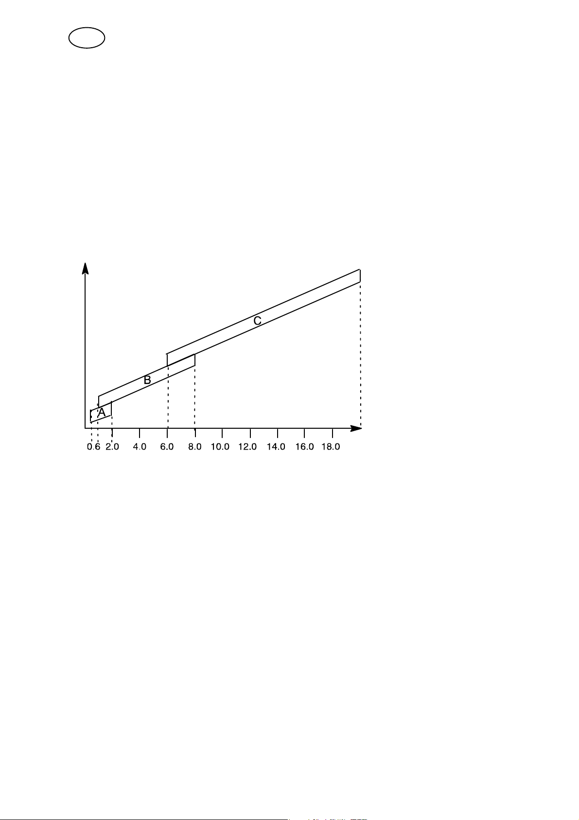
4.3.2 Different pulsing methods
Below you can see which pulsing method can be used, depending on the plate
thickness that is to be welded.
Heat
C
Spray in primary phase and
pulsing in secondary phase
B
Pulsing in primary phase and
pulsing in secondary phase
A
Pulsing in primary phase and
short arc in secondary phase
Plate dimension
4.3.3 Wire feed unit
Only use wire feed unit Feed 3004 during SuperPulse welding.
Precautionary measures!
When using SuperPulse, there is a considerable load on the wire feed unit. In order
of the functional safety of the wire feed unit not to be endangered, follow the limit
values in the following diagram.
bi23e
- 27 -
© ESAB AB 2012

GB
Difference in the wire feed speed
m/min
The graphs for 15 m/min and 20 m/min relate to primary wire feed speed. The cycle
time is the sum of primary and secondary phase time.
The difference between primary and secondary wire feed speed may not exceed the
speed that is specified by the graphs for primary wire speed.
Example: If the cycle time is 0.25 s and the primary wire feed speed is 15 m/min, the
difference between primary and secondary wire feed speed may not exceed
6 m/min.
Weld example A
In this example we will weld a 10 mm plate with 1.2 mm aluminium wire and
argon shielding gas
Make the following settings with the control panel:
Process Superpulse Superpulse
Phase Primary Secondary
Method Short-/Sprayarc Pulsing
Wire type AlMg AlMg
Shielding gas Ar Ar
Wire diameter 1.2 mm 1.2 mm
Voltage (+ 1.0V) (+ 3.0V)
Wire feed speed 15.0 m/min 11.0 m/min
Phase time 0.1 s 0.1 s
Primary and secondary phase time are 0.1 s + 0.1 s = 0.2 s.
The difference in wire feed speed is 15.0 m/min - 11.0 m/min = 4 m/min.
- 28 -
bi23e
© ESAB AB 2012
 Loading...