


INSTRUCTIONS for
TYPE 'E', 'E'/FG-2, & 'E'/LPNG
Cutting Range using any fuel gas .................................. 1/8" - 12"
Cutting Nozzles ........................................................... 4200 series
Torch-Hose Connections.................. Oxy, - CGA-022 (9/16" - 18)
Torch Overall Length ...................................................... 20-1/2-in.
Weight .................................................................................... 3 lbs.
F-9544-P
June, 2009
CUTTING TORCHES
F.G. - CGA-023 (9/16" - 18 LH)
OPERATION INSTRUCTIONS
CONNECTING
The Type 'E' cutting torch is designed for optimum
flashback resistance with acetylene. The Type 'E'/FG2 is for use with other fuel gases such as FG-2, natural
gas, propane, MAPP,etc. The 'E'/LPNG torch is designed for use with natural gas where supply pressure
is less than 1/2 psig. Do NOT use Type 'E'/FG-2 or 'E'/
LPNG torch with acetylene. Flashback may occur
quickly and damage the torch.
1. Attach regulators to the oxygen and fuel gas cylinders. Follow all instructions supplied with the regulators.
2. Attach oxygen and fuel gas hoses to the regulators
and to the torch, after making sure all metal seating
surfaces are clean. Tighten all connection nuts with
a wrench.
3. Attach nozzle to torch head, and tighten connection
nut with a wrench.
4. Check throttle valve packing nuts for tightness.
Third Party Listed
Third Party Listed
TESTING FOR LEAKS
Every cutting outfit should be thoroughly tested for leaks
after it is first hooked up, and at regular intervals thereafter. After all connections have been made, make sure
all valves on the torch handle are closed. Then turn in
the regulator pressure-adjusting screws until the oxygen delivery-pressure gauge registers 60 psi and the
fuel gas delivery-pressure gauge registers 10 psi. Using
Leak Test Solution suitable for oxygen service, such as
P/N 998771 (8 oz. container), check for leaks at the
cylinder valves, the cylinder-to-regulator connections,
the regulator-to-hose connections, and the hose-totorch connections. If bubbling at any point indicates
leakage, tighten the connection. If this does not stop the
leakage, close the appropriate cylinder valve, open the
corresponding torch valve to remove all pressure from
the line, and finally release the regulator pressure adjusting screw by turning it counterclockwise. Then
Be sure this information reaches the operator.
You can get extra copies through your supplier.
READ AND UNDERSTAND INSTRUCTION MANUAL BEFORE INSTALLING
OR OPERATING. PROTECT YOURSELF AND OTHERS!
CAUTION
These INSTRUCTIONS are for experienced operators. If you are not fully familiar with the principles of operation and safe practices for gas welding and cutting equipment, we urge you to read
our booklet, “Precautions and Safe Practices for Gas Welding, Cutting, and Heating,” Form F-2035.
Do NOT permit untrained persons to install, operate, or maintain this equipment. Do NOT attempt
to install or operate this equipment until you have read and fully understand these instructions. If
you do not fully understand these instructions, contact your supplier for further information. Be
sure to read the Safety Precautions before installing or operating this equipment.
USER RESPONSIBILITY
This equipment will perform in conformity with the description thereof contained in this manual and accompanying labels and/or inserts when installed, operated, maintained and repaired in accordance with the instructions provided. This equipment must be checked periodically. Malfunctioning or poorly maintained equipment
should not be used. Parts that are broken, missing, worn, distorted or contaminated should be replaced immediately. Should such repair or replacement become necessary, the manufacturer recommends that a telephone
or written request for service advice be made to the Authorized Distributor from whom it was purchased.
This equipment or any of its parts should not be altered without the prior written approval of the manufacturer.
The user of this equipment shall have the sole responsibility for any malfunction which results from improper
use, faulty maintenance, damage, improper repair or alteration by anyone other than the manufacturer or a service facility designated by the manufacturer.
IMPORTANT SAFEGUARDS
When using Oxy-Fuel Gas Torches, basic safety precautions should always be followed:
Never use Acetylene gas at a pressure over 15 psig.a.
Never use damaged equipment.b.
Never use oil or grease on or around Oxygen equipment.c.
Never use Oxygen or fuel gas to blow dirt or dust o clothing or equipment.d.
Never light a torch with matches or a lighter. Always use a striker.e.
Always wear the proper welding goggles, gloves and clothing when operating Oxy-Acetylene equipment. f.
Pants should not have cus.
Do not carry lighters, matches or other ammable objects in pockets when welding or cutting.g.
Always be aware of others around you when using a torch.h.
Be careful not to let welding hoses come into contact with torch ame or sparks from cutting.i.
SAVE THESE INSTRUCTIONS.j.
BE SURE THIS INFORMATION REACHES THE OPERATOR.
YOU CAN GET EXTRA COPIES THROUGH YOUR SUPPLIER.
SAVE THESE INSTRUCTIONS!

SAFETY PRECAUTIONS
These Safety Precautions are for your protection. They summarize precautionary information from the references listed
in Additional Safety Information section. Before performing any
installation or operating procedures, be sure to read and follow the safety precautions listed below as well as all other
manuals, material safety data sheets, labels, etc. Failure to observe Safety Precautions can result in injury or death.
PROTECT YOURSELF AND OTHERS - Some
welding, cutting and gouging processes are
noisy and require ear protection. Hot metal can
cause skin burns and heat rays may injure
eyes. Training in the proper use of the processes and equipment is essential to prevent
accidents. Also:
1. Always wear safety glasses with side shields in any work area,
even if welding helmets, face shields, or goggles are also required.
2. Wear flameproof gauntlet type gloves, heavy long-sleeve shirt,
cuffless trousers, high-topped shoes, and a welding helmet or
cap for hair protection, to protect against hot sparks and hot
metal. A flameproof apron may also be desirable as protection
against radiated heat and sparks.
3. Hot sparks or metal can lodge in rolled up sleeves, trousers
cuffs, or pockets. Sleeves and collars should be kept buttoned,
and open pockets eliminated from the front of clothing.
4. Protect other personnel from hot sparks with a suitable nonflammable partition or curtains.
5. Use goggles over safety glasses when chipping slag or grinding. Chipped slag may be hot and can travel considerable distances. Bystanders should also wear goggles over safety
glasses.
FIRES AND EXPLOSIONS - Heat from a flame
can act as an ignition source. Hot slag or sparks
can also cause fires or explosions. Therefore:
1. Remove all combustible materials well away from the work
area or completely cover the materials with a protective nonflammable covering. Combustible materials include wood,
cloth, sawdust, liquid and gas fuels, solvents, paints and coatings, paper, etc.
2. Hot sparks or hot metal can fall through cracks or crevices in
floors or wall openings and cause a hidden smoldering fire on
the floor below. Make certain that such openings are protected
from hot sparks and metal.
3. Do not weld, cut, or perform any other hot work on materials,
containers, or piping until it has been completely cleaned so
that no substances on the material can produce flammable or
toxic vapors. Do not do hot work on closed containers. They
may explode.
4. Have fire extinguishing equipment handy for instant use, such
as a garden hose, a pail of water or sand, or portable fire
extinguisher. Be sure you are trained in its use.
5. After completing operations, inspect the work area to be sure
that there are no hot sparks or hot metal which could cause a
later fire. Use fire watchers when necessary.
6. For additional information, refer to NFPA Standard 51B, Fire
Prevention in Use of Cutting and Welding Processes, which
is available from the National Fire Protection Association,
Batterymarch Park, Quincy, MA 02269.
FUMES AND GASES - Fumes and gases, particularly in confined spaces, can cause discomfort or injury. Do not breathe fumes or
gases from welding or cutting, Therefore:
1. Always provide adequate ventilation in the work area by natural or mechanical ventilation means. Do not weld, cut, or gouge
on materials such as galvanized steel, stainless steel, copper,
zinc, lead, beryllium, or cadmium unless positive mechanical
ventilation is provided. Do not breathe fumes and gases from
these materials.
2. If you develop momentary eye, nose, or throat irritation while
operating, this is an indication that ventilation is not adequate.
Stop work at once and take necessary steps to improve ventilation in the work area. Do not continue to operate if physical
discomfort persists.
3. Refer to ANSI/ASC Standard Z49.1 listed below for specific
ventilation recommendations.
4. WARNING: This product, when used for welding or
1. Always have qualified personnel perform the installation,
troubleshooting, and maintenance work. Do not operate or
repair any equipment unless you are qualified to do so.
2. Keep all oxy-fuel equipment free of grease or oil. Grease, oil,
and other similar combustible materials, when ignited, can burn
violently in the presence of oxygen.
3. Do not abuse any equipment or accessories. Keep equipment
away from heat and wet conditions, oil or grease, corrosive
atmospheres and inclement weather.
4. Keep all safety devices in position and in good repair.
5. Use equipment for its intended purpose. Do not modify it in
any manner.
1. Use the proper gas for the process and use the proper pressure reducing regulator designed to operate from the compressed gas cylinder. Do not use adaptors to mount the regulator on the cylinder. Maintain hoses and fittings in good condition. Follow manufacturers operating instructions for mounting the regulator to the gas cylinder.
2. Always secure cylinders in an upright position by chain or strap
to suitable hand trucks, benches, walls, post, or racks. Never
secure cylinders to work tables or fixtures where they may
become part of an electrical circuit.
3. When not in use, keep cylinder valves closed. Have the valve
protection cap in place on top of the cylinder if no regulators is
installed. Secure and move cylinders by using suitable hand
trucks. Avoid rough handling of cylinders.
4. Locate cylinders away from heat, sparks, or flame of a welding, cutting, or gouging operation. Never strike an arc on a
cylinder.
5. For additional information, refer to CGA Standard P-1, Precautions for Safe Handling of Compressed Gases in Cylinders:, which is available from the Compressed Gas Association, 1235 Jefferson Davis Highway, Arlington, VA 22202.
The following publications, which are available from the American
Welding Society, 550 N.W. LeJuene Road, Miami, FL 33126, are
recommended to you:
1. ANSI/AWS Z49.1 - Safety in Welding and Cutting.
2. AWS F4.1 - Recommended Safe Practices for the Preparation for Welding and Cutting of Containers and Piping That
Have Held Hazardous Substances/
3. AWS SP - Safe Practices - Reprint, Welding Handbook.
cutting, produces fumes or gases which
contain chemicals known to the State of
California to cause birth defects and, in
some cases, cancer. (California Health &
Safety Code §25249.5 et seq.)
EQUIPMENT MAINTENANCE - Faulty or improperly maintained equipment, such as
torches, hoses and regulators, can result in
poor work, but even more important, it can
cause injury or death through fires. Therefore:
GAS CYLINDER HANDLING - Gas cylinders, if mishandled, can rupture or explode violently. Sudden
rupture of a cylinder, valve or relief device can injure or kill you. Therefore:
ADDITIONAL SAFETY INFORMATION - For more information on safe practices for oxy-fuel welding and
cutting equipment, ask your distributor for a copy
of Precautions and Safe Practices for Gas Welding, Cutting, and Heating, Form 2035. Gas apparatus safety guidelines are also available on video cassettes from your distributor.
MEANING OF SYMBOLS - As used throughout
this manual: Means Attention! Be Alert! Your
safety is involved.
Means immediate hazards which, if not avoided,
will result in immediate, serious personal in-
jury or loss of life.
Means potential hazards which could result in
personal injury or loss of life.
Means hazards which could result in minor
personal injury.
2
SP-GA 10/98

break the leaky connection, wipe metal seating surfaces
with a clean dry cloth, and examine them for nicks and
scratches. Remake the connection(s) and retest. Do
not try to light the torch until you are satisfied that all
connections are gas tight.
ADJUSTING GAS PRESSURE
Fuel Gas: Open the fuel gas valve about one turn. Turn
in the pressure-adjusting screw on the fuel gas regulator
until its delivery-pressure gauge registers the desired
pressure (see cutting chart on page 4 or 5). Then
immediately close the fuel gas valve.
Oxygen: Open the cutting oxygen valve by depressing
its valve lever fully. Turn in the pressure-adjusting screw
on the oxygen regulator until its delivery-pressure gauge
registers the desired pressure (see chart on page 4 or 5).
Then release the cutting oxygen lever.
NOTE: When gaugeless regulators are used, do not
open torch valves. Merely turn in the pressureadjusting screws to the desired pressures as
indicated on the scales of the regulator caps.
LIGHTING AND FLAME ADJUSTMENT
CAUTION: Use friction lighter for lighting torch. Do
NOT use a match. Use of a match can
seriously burn your hand.
Using Acetylene
1. Open the acetylene valve on the torch about 1/2 turn,
and light the gas at the nozzle.
2. Slowly close the acetylene valve unit the yellow flame
just starts to throw off black smoke.
3. Slowly open preheat oxygen valve on torch until
neutral flames are obtained.
4. Finally, open the cutting oxygen valve by depressing
lever and readjust for neutral flames by turning preheat oxygen valve.
The flame now has the proper strength for any cutting
job. With this flame, acetylene is being consumed
economically and the torch will be operating at best
resistance to flashback. If greater preheat flame temperature is desired for faster starts or piercing, open the
cutting oxygen valve and adjust the preheat oxygen
valve until the flame inner cones shorten about 10
percent and become sharply pointed.
Using Fuel Gases except Acetylene
1. Crack the fuel gas valve and light the gas at the
nozzle.
2. Open fuel gas valve until flame starts to leave the end
of the nozzle.
3. Slowly open preheat oxygen valve on torch until flame
stabilizes.
4. Depress lever to open cutting oxygen valve and then
adjust preheat oxygen valve until preheat flames are
at their shortest length.
5. If larger or smaller preheat flames are desired, depress cutting oxygen valve lever and alternately readjust fuel gas and preheat oxygen valve to obtain the
final flame setting.
SHUTTING OFF
Release the cutting oxygen valve lever. Then close the
fuel gas valve, and finally the preheat oxygen valve.
If operations are to be stopped for a half-hour or more, all
pressure should be released from the torch, hoses, and
regulators by doing the following:
1. Close each cylinder or station valve.
2. Open torch valves.
3. After relieving the gases, back out the pressureadjusting screw of each regulator and close the torch
valves.
OPERATING PRECAUTIONS
Do not exceed 15 psig acetylene during operation.
Flow: There must be proper flow of gases for safe
operation and full performance. This requires the following three conditions: (1) the regulators that determine the
inlet pressure to the hoses must be set to the correct
pressure: (2) the hoses and their connectors must have
adequate capacity for the job (hoses that are too long,
too small or have connectors with small passageways
can cause problems); and (3) the throttle valves on the
torch must be adjusted with the procedure shown in
these instructions.
Note: Items (1) and (2) can be checked by measuring
the gas pressures at the torch. Gauge adaptors
are available for this purpose.
Backfire: Improper operation of the torch or cutting
attachment may cause the flame to go out with a loud
‘pop’. (If you are welding, the flame will often reignite
instantly.) Such a backfire may be caused by contact of
tip or nozzle with the work, by spatter from the work, by
the use of incorrect gas pressures, or by leakage at the
cutting nozzle seats due to dirt or nicks on seats or to a
loose nozzle nut. After a backfire, you can normally
relight the flames immediately. However, if backfires
occur repeatedly, shut off the torch. Check the ‘O’ ring
seals between the welding head or cutting attachment
and the handle, and the nozzle seats (if cutting). Readjust operating pressure (see tables on pages 4 and 5)
and relight.
Flashback: Under certain circumstances, the flame
may not ‘pop’ out (backfire) but instead burn back inside
the torch with a shrill hissing or squeal. This is called a
‘flashback’. A flashback should never occur if (1) the
equipment is in good condition; (2) preheat ports on
cutting nozzles or welding tips are cleaned frequently;
(3) operating pressures are correct; and (4) throttle
valves are adjusted properly. Should a flashback occur,
IMMEDIATELY shut off the torch. Allow it to cool off for
at least a minute. Then check your nozzle or tip, gas
pressures, readjust regulators if necessary, and relight
the torch. If flashback recurs, send the torch handle and
welding head or cutting attachment to your distributor for
repair.
3

OPERATING DATA
1. The tables show average values based on typical conditions. The type and quality of steel, its surface condition, the
purity of oxygen, etc. will always have a bearing on the end results.
2. If cutting up to 4-in. thick steel, 1/4-in. oxygen and fuel gas hoses up to 25-ft. long are suitable. For heavier cuts or
if longer hoses are required, 3/8-in. hoses are recommended.
4202 Series Acetylene General Purpose Nozzles
Nozzle Steel Pressure, psig Gas Consumption, Cleaning
Thickness, ft
3
/hr Drill Size
Size Part No. in. Oxygen Acetylene Oxygen Acetylene Preheat Cutting
1/8" 638869 1/8 30-40 5 31-34 8-9 73 76
1/4" 16K08 1/4 25-30 5 42-45 8-10 73 68
1/2" 16K09 1/2 30-40 5 70-75 10-12 73 60
1-1/2" 16K10 3/4 25-30 5 95-100 12-14 69 52
1 35-40 6 120-125 14-16
1-1/2 50-55 7 165-170 16-18
4" 16K11 2 40-45 5 195-200 18-20 68 50
3 45-60 6 230-235 20-22
4 50-55 6 315-320 23-25
6" 16K12 6 60-70 8 460-470 30-32 64 43
10" 16K13 8 65-75 10 605-615 36-38 60 35
10 80-90 12 680-740 40-45
12" 16K14 12 80-90 12 800-860 45-50 56 30
4207 Series Acetylene Gouging Nozzles
Nozzle Groove Gas Pressure, Gas Conumption, Cleaning Tool*
Dimensions, psig cu. ft./hr. Gouging
in (approx.) Speed
Size Part No. Width Depth Oxygen Acetylene Oxygen Acetylene ft./min. Preheat Cutting
13 16K67 1/4-5/16 1/8-1/4 35-40 9-10 157-180 33-38 1.0-1.8 5190068 5190071
19 16K35 3/8-7/16 1/4-3/8 45-50 12-14 268-303 50-55 1.6-2.2 5190069 5190072
*Use the listed special cleaning tools only. DO NOT use twist drills.
4213 Series Fuel Gas Two-Piece Nozzles
NOTE: DO NOT use with Acetylene.
Nozzle Sleeve (External)u Steel Pressure, psig Gas Consumption Cleaning
Nozzle (Internal) Part No. Thickness, ft3/hr Drill Size
Size Part No. Long Medium Short In. Oxygen Fuel Gas² Oxygen FG-2n Nat. Gas Cuttingl
3 16K68 16K74 998562 114Z10 1/4 25-30 4-5 50-55 8-12 12-15 68
4 16K69 16K74 998562 114Z10 1/2 40-45 5-6 85-95 10-14 20-23 60
3/4 20-25 6-7 125-135 12-16 20-23
6 16K70 16K75 998563 114Z11 1 25-30 6-7 135-145 12-16 20-23 53
1-1/2 45-50 6-7 195-205 12-16 20-30
2 30-35 7-8 220-230 14-20 30-40
8 16K71 16K75 998563 114Z11 3 40-45 7-8 265-275 14-20 30-40 46
4 60-65 7-8 355-365 14-20 30-40
6 55-60 9-15 460-500 20-25 40-45
10 16K72 16K75 998563 114Z11 8 80-90 9-15 640-680 20-25 40-50 39
10 90-100 9-15 750-800 20-25 50-65
12 16K73 16K75 998563 114Z11 12 90-105 10-20 900-1000 25-30 70-75 31
u
Long - For use with natural gas, propane, and butane.
Medium - For use with methylacetylene - propadiene (MPS) and propylene-based fuel gases where high preheat intensity is desired.
Short - For use with methylacetylene - propadiene (MPS) and propylene-based fuel gases for general purpose cutting.
n
Consumption of MAPP or propane is approximately the same as FG-2.
l
Use soft bristled brush (750F99) to clean preheat slots of internal nozzles.
If using LPNG injector (19417) in torch, it will operate with natural gas pressure less than 1/2 psig.
²
4

4216 Series Fuel Gas One-Piece Cutting Nozzles
NOTE: Primarily designed for use with FG-2 or MAPP. May be used with acetylene if heavy preheat is
desired.
Nozzle Steel Gas Pressure, Gas Consumption Cleaning Drill
Thickness, psig ft3/hr Size
Size Part No. in. Oxygen Fuel Gas Oxygen Fuel Gas Preheat Cutting
1/4" 998589 1/4 20-25 3-5 55-60 3-4 67 68
1/2" 998590 1/2 30-35 3-5 70-80 4-5 67 60
1-1/2" 998591 3/4 30-35 3-5 135-155 7-8 64 53
1 35-40 3-5 150-165 7-8
1-1/2 40-45 3-5 160-210 8-9
4" 998592 2 25-30 3-5 215-245 8-10 62 46
3 30-35 3-5 235-290 8-10
4 35-40 3-5 270-320 10-11
8" 998593 6 35-45 5-10 410-480 11-13 59 39
8 55-65 5-10 580-670 15-17
12" 998594 10 40-50 10-15 580-805 20-23 56 31
12 55-65 10-15 845-975 22-28
4217 Series Fuel Gas Two-Piece Cutting Nozzles
Nozzle Sleeve Steel Pressure, psig Gas Consumption, ft3/hr Cleaning
Nozzle (Internal) (External) Thickness, Fuel Gas Fuel Gas Drill Size
Size P/N P/N in. Oxygen FG-2 Propane Nat. Gas² Oxygen FG-2 Propane Nat Gas Cuttingl
1/4" 19485 1/4" 30 4 6 7 70 8 12 30 68
1/2" 19486 19518 1/2" 35 4 7 8 120 9 14 32 60
1" 19487 1" 40 4 8 9 180 10 15 35 53
2" 19488 2" 45 5 9 10 250 11 16 40 50
4" 19489 4" 40 4 8 10 370 12 18 45 43
6" 19490 19519 6" 50 5 12 13 520 14 20 50 39
8" 19491 8" 50 6 15 16 610 16 22 55 35
12" 19492 12" 75 8 18 20 860 20 30 85 31
² If using LPNG injector (19417) in torch, it will operate with natural pressure less than 1/2 psig.
l Use soft-bristled brush (750F99) to clean preheat slots of internal nozzles.
5

MAINTENANCE INSTRUCTIONS
For all repairs other than those covered below, send
the torch to your welding equipment distributor or to
ESAB Remanufacturing Center, Ebenezer Road, Florence, SC 29501. Improperly repaired apparatus is
hazardous.
Preheat Throttle Valves: Leakage around either throttle
valve can almost always be corrected by tightening the
packing nut slightly.
If either preheat valve will not shut off completely, loosen
the packing nut and remove the valve assembly. Wipe
the end of the valve stem, and the seating surface in the
body, with a clean cloth. Then reinstall the valve and
retighten the packing nut.
If the valve still leaks, install a new throttle valve assembly. After you do so, tighten the packing nut until you find
it extremely difficult to turn the valve wheel. Set the unit
aside for a few hours to set the packing. Then loosen the
packing nut until the throttle valve turns readily.
If leakage through either preheat valve is still evident
after a new throttle valve assembly has been installed,
send the torch to a remanufacturing center or to your
distributor for reseating.
5. Screw the entire assembly into the torch body and
tighten firmly with a wrench. Reassemble the cutting
valve lever to the torch body.
Mixer: To remove the torch mixer for cleaning or re-
placement, unscrew the lower tube nut completely and
then pull the entire front end assembly (1053, 1054, or
1048) from the torch. The mixer can now be pulled
straight out from the lower tube.
To clean a mixer, use correct size twist drills (see mixer
table below) or soak the mixer overnight in a solution of
OXWELD Nozzle Cleaning Compound (P/N 761F00),
rinse, and blow dry with clean air.
Mixer Cleaning Drill Size
Part Recommended Center Side
No. U se Orifice Orifice
19048* Acetylene 48 68
19050† Acetylene-for max. 39 60
preheat & large nozzles
19049* FG-2, Natural Gas 36 57
19417* Low Press. 63 53
Natural Gas (LPNG)
* 19048 is supplied with Type 'E' acetylene torch.
19049 is supplied with Type 'E'/FG-2 torch.
19417 is supplied with Type 'E'/LPNG torch.
† Accessory
Cutting Valve: If leakage is detected between the cut-
ting valve stem cap and the valve, or if the cutting valve
fails to shut off completely, remove cutting valve lever
and then unscrew the valve assembly (08M05), You
may either replace the entire valve assembly or disassemble the valve assembly to replace valve stem (19216),
seat (19215), and O-ring (14K11). If the latter, unscrew
the valve stem from the cap (824). Using the new valve
stem, seat, and O-ring, reassemble the valve as follows:
1. Place the new O-ring and retaining washer (10K23) in
the valve nut (19217).
2. Insert the valve spring (23K07) behind the retaining
washer and hold in place firmly while inserting new
seat, and then new valve stem through the valve nut
and O-ring.
3. Screw the valve stem into the valve stem cap firmly.
4. Replace O-ring (14K07) about the seat of the valve
nut if O-ring appears distorted.
Inspect O-rings (14K07, 85W43, and 2064101) and
replace them if they are not in good condition.
Cleaning Cutting Nozzles: If the cutting nozzle does
not produce straight, uniform flames, or if any of the
nozzle orifices become clogged, clean them by hand
with the correct size twist drills shown in the table on
page 4, or with OXWELD tip cleaners. (The relationship
between OXWELD tip cleaners and drill sizes is shown
on the tip cleaner case.)
To clean the preheat slots on internal nozzles, remove
the external sleeve and use a soft bristled brush (750F99).
For longer life, nozzles should be cleaned periodically in
a solution of OXWELD Nozzle Cleaning Compound
(P/N 761F00) made up and use as directed on the jar in
which it is packed.
6
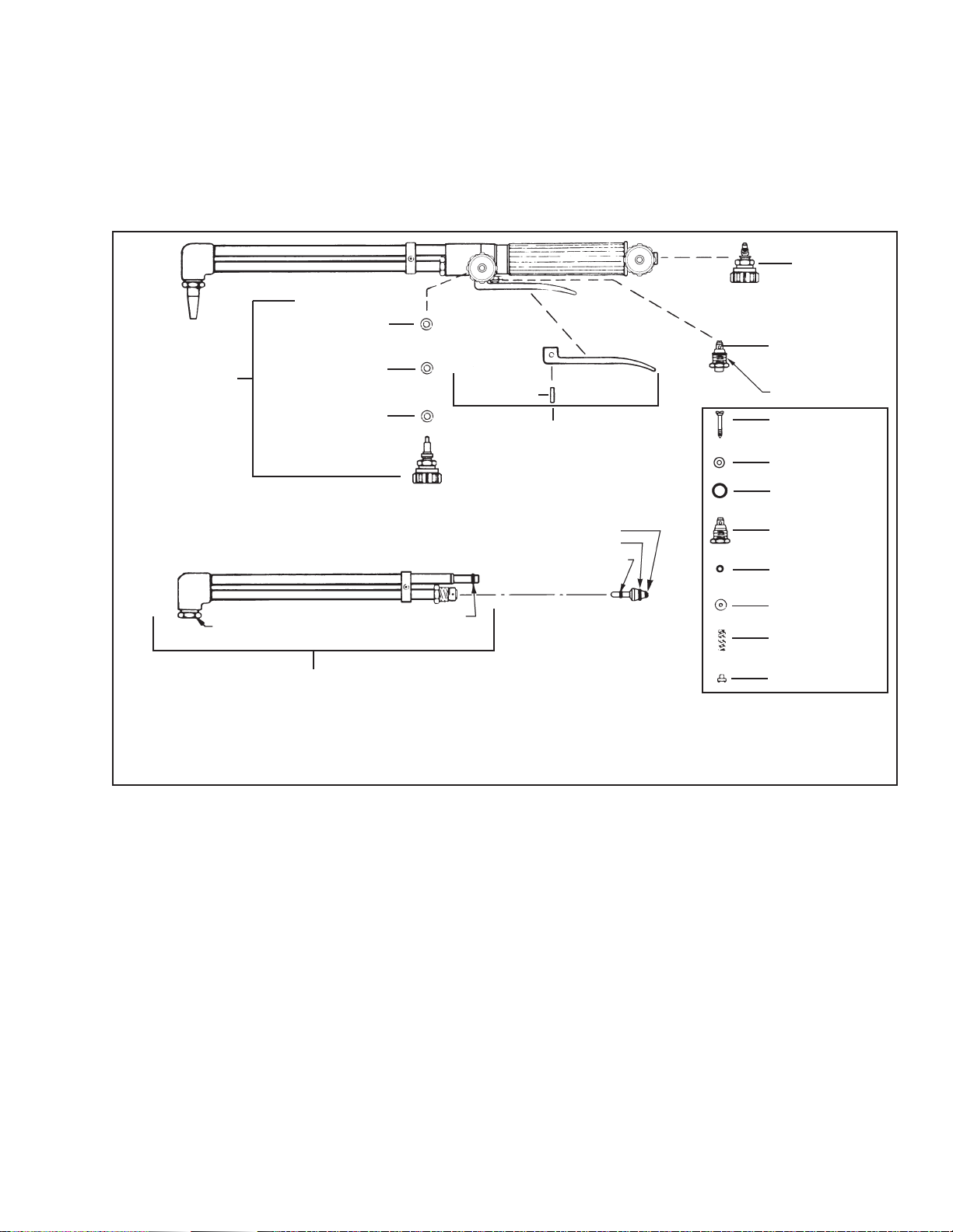
PARTS INFORMATION
All parts which can be replaced without breaking soldered or brazed joints are illustrated and listed
below. When ordering parts, please give both part number and description (including size where
appropriate). Parts may be ordered from your welding equipment distributor or from ESAB Welding
& Cutting Products, Customer Service Department, Florence, SC.
FG THROTTLE
VALVE ASSEM. 18255
OXY
WASHER - 834
THROTTLE
VALVE
ASSEM. - 19051
NUT - 802
FRONT END ASSEM. (90°) - 1054 (ILLUS.)
u 1. Orient slot of roll pin to face down.
2. If replacing screw and washer on torches made prior to 8/83 with roll pin, open holes through lever to 0.166" dia. (No. 19 drill). and
open hole through body to 5/32" dia.
* Includes "O" -Ring - 14K07
WASHER - 10K18
WASHER - 834
"O" RING - 85W10
(75°) - 1053
(180°) - 1048
u ROLLPIN 5/32" x 9/16"
LEVER ASSEM. - 1069
MIXER - 19048 ("E" ACET)
19049 ("E"/FG-2)
19417 ("E"/LPNG)
includes:
O-RING - 85W43
O-RING - 14K07
O-RING - 2064101
CUTTING VALVE
ASSEM. - 08M05
9/16" - 27
VALVE STEM 19216
SEAT - 19215
"O" RING - 14K07
NUT - 19217*
"O"RING - 14K11
WASHER - 10K23
SPRING - 23K07
CAP - 824
Type 'E' Acetylene Cutting Torch, 75° Head .................. P/N 04L04
Type 'E' Acetylene Cutting Torch, 90° Head .................. P/N 04L06
Type 'E' Acetylene Cutting Torch, 180° Head ................ P/N 04L16
Type 'E'/FG-2 Cutting Torch, 75° Head ......................... P/N 998259
Type 'E'/FG-2 Cutting Torch, 90° Head ......................... P/N 998260
Type 'E'/LPNG Cutting Torch, 75° Head ......................... P/N 19574
Type 'E'/LPNG Cutting Torch, 90° Head ......................... P/N 19573
7


ESAB Welding & Cutting Products, Florence, SC Welding Equipment
COMMUNICATION GUIDE - CUSTOMER SERVICES
A. CUSTOMER SERVICE QUESTIONS:
Telephone: (800)362-7080 / Fax: (800) 634-7548 Hours: 8:00 AM to 7:00 PM EST
Order Entry Product Availability Pricing Order Information Returns
B. ENGINEERING SERVICE:
Telephone: (843) 664-4416 / Fax : (800) 446-5693 Hours: 7:30 AM to 5:00 PM EST
Warranty Returns Authorized Repair Stations Welding Equipment Troubleshooting
C. TECHNICAL SERVICE:
Telephone: (800) ESAB-123/ Fax: (843) 664-4452 Hours: 8:00 AM to 5:00 PM EST
Part Numbers Technical Applications Specications Equipment Recommendations
D. LITERATURE REQUESTS:
Telephone: (843) 664-5562 / Fax: (843) 664-5548 Hours: 7:30 AM to 4:00 PM EST
E. WELDING EQUIPMENT REPAIRS:
Telephone: (843) 664-4487 / Fax: (843) 664-5557 Hours: 7:30 AM to 3:30 PM EST
Repair Estimates Repair Status
F. WELDING EQUIPMENT TRAINING
Telephone: (843)664-4428 / Fax: (843) 679-5864 Hours: 7:30 AM to 4:00 PM EST
Training School Information and Registrations
G. WELDING PROCESS ASSISTANCE:
Telephone: (800) ESAB-123 Hours: 7:30 AM to 4:00 PM EST
H. TECHNICAL ASST. CONSUMABLES:
Telephone : (800) 933-7070 Hours: 7:30 AM to 5:00 PM EST
IF YOU DO NOT KNOW WHOM TO CALL
Telephone: (800) ESAB-123
Fax: (843) 664-4462
Hours: 7:30 AM to 5:00 PM EST
or
visit us on the web at http://www.esabna.com
The ESAB web site oers
Comprehensive Product Information
Material Safety Data Sheets
Warranty Registration
Instruction Literature Download Library
Distributor Locator
Global Company Information
Press Releases
Customer Feedback & Support
 Loading...