


TIG 400i
INVERTER TIG
Welding Power Source
Instruction manual
Ver:3.0 3220
TIG 400i
INVERTER WELDING POWER SOURCE
Instruction manual
For
Installation, Operation & General maintenance
1

CONTENTS
Item Page No.
SAFETY
RATING AND INSTALLATION 5-7
CAUTIONS FOR INSTALLATION 7-8
WELDING OPERATIONS 9-11
WIRING DIAGRAM 12
GENERAL MAINTENANCE 13
PARTS LIST AND EXPLODED VIEW
3-4
14-17
ESAB INDIA CONTACT DETAIL 18
2

SAFETY
Users of ESAB welding equipment have the ultimate responsibility for ensuring that
anyone who works on or near the equipment observes all the relevant safety
precautions. Safety precautions must meet the requirements that apply to this type of
welding equipment. The following recommendations should be observed in addition to
the standard regulations that apply to the workplace.
Trained personnel well acquainted with the operation of the welding equipment must
carry out all the work. Incorrect operation of the equipment may lead to hazardous
situations, which can result in injury to the operator and damage to the equipment.
1. Anyone who uses the welding equipment must be familiar with:
• its operation
• location of emergency stops
• its function
• relevant safety precautions
• welding
2. The operator must ensure that:
• no unauthorized person is stationed within the working area of the equipment
when it is started up.
• no one is unprotected when the arc is struck
3. The workplace must:
• be suitable for the purpose
• be free from drafts
4. Personal safety equipment
• Always wear recommended personal safety equipment, such as safety glasses,
flameproof clothing, and safety gloves.
• Do not wear loose—fitting items, such as scarves, bracelets, rings, etc., which
could become trapped or cause burns.
5. General precautions
• Make sure the return cable is connected securely.
• Only a qualified electrician may carry out work on high voltage equipment.
• Appropriate fire extinguishing equipment must be clearly marked and close at
hand.
• Lubrication and maintenance must not be carried out on the equipment during
operation.
Read and understand the instruction manual before installing or operating.
3
ESAB can provide you with all necessary welding protection and accessories.
• Ensure your working stance is safe.
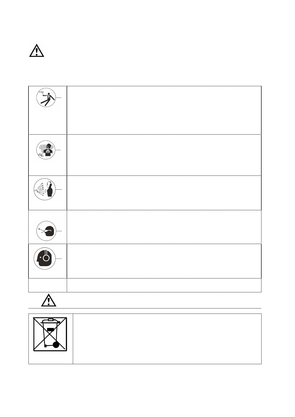
PROTECT YOURSELF AND OTHERS!
WARNING
Arc welding and cutting can be injurious to yourself and others. Take
precautions when welding.
Ask for your employer’s safety practices which should be based on manufacturers’
hazard data.
ELECTRIC SHOCK – Can kill
• Install and earth the welding unit in accordance with applicable
standards.
• Do not touch live electrical parts or electrodes with bare skin, wet
gloves or wet clothing.
• Insulate yourself from earth and the workpiece.
FUMES AND GASES – Can be dangerous to health
• Keep your head out of the fumes.
• Use ventilation, extraction at the arc, or both, to take fumes and gases
away from your breathing zone and the general area.
ARC RAYS – Can injure eyes and burn skin.
• Protect your eyes and body. Use the correct welding screen and filter
lens and wear protective clothing.
• Protect bystanders with suitable screens or curtains.
FIRE HAZARD
• Sparks (spatter) can cause fire. Make sure therefore that there are no
inflammable materials nearby.
NOISE – Excessive noise can damage hearing
• Protect your ears. Use earmuffs or other hearing protection.
• Warn bystanders of the risk.
MALFUNCTION – Call for expert assistance in the event of malfunction.
This product is solely intended for arc welding
Do not dispose of electrical equipment together with normal waste!
In accordance with national law, electrical equipment that has
reached the end of its life must be collected separately and returned
to an environmentally compatible recycling facility. As the owner of
the equipment, you should get information on approved collection
systems from the local representative. By applying this Directive you
will improve the environment and human health
CAUTION!
4

RATING
manual welding
argon arc welding
MMA: 400
range
MMA
:10-400
(Ar
gon arc welding)
(Manual welding)
characteristic
RATING OF TIG 400i INVERTER WELDING POWER SOURCE
Contents of parameters Unit TIG 400i
No-load voltage V 76
The working voltage of
V 20.4-36.0
Output
Input
The working voltage of
Rated welding current A
Current adjustment
Rated load duty cycle
(Argon arc welding)
Rated load duty cycle
(Manual welding)
Number of phases Phase 3
Frequency HZ 50/60
Supply voltage V 415V ±15%
Rated input current
Maximum effective
input current
(Argon arc welding)
Rated input current
V 10.4-26.0
TIG: 400
A
A 18
A 14
A 24
TIG:10-400
400A @ 60%
310A @100%
305A @ 60%
240A @ 100%
Maximum effective
input current
(Manual welding)
Rated input capacity KVA 17
Static external characteristic
Lifting device Handle
Efficiency η ≥85%
Power Factor 0.9
Insulation grade H
Enclosure protection grade IP21S
Weight Kg 35
Boundary dimensions (L* W* H) mm 510×275×420
5
A 14
Down slope

INSTALLATION
Input wiring
o Ensure that the voltage, number of phases, frequency and capacity of the input
power are consistent with the calibration values on the nameplate of the welding
machine.
o Wiring shall be performed by professional electrician.
o The input cable and air inlet are located on the back panel of the welding machine.
Please refer to the structure diagram of welding machine for detailed location.
o Connect the input cable to the power to ensure the reliable connection.
o The casing must be grounded, and the grounding bolt is located at the lower right
corner of the back panel of the welding machine and marked with a grounding
mark.
o Confirm the air inlet is connected smoothly with the argon cylinder during the weld
of argon arc welding.
o The recommended specifications of ground wire, fuse protector or breaker are as
follows:
Specifications for input cables, ground wires and input fuse protectors or breakers at three-phase /50Hz
rated load duty cycle
Welding
machine
model
TIG 400i 60% 415V 24A 14A ≥4 mm2 ≥4 mm2 60 A
Load duty
cycle
Input
voltage
Input
current
Maximum
effective
input
current
60℃ cable specification
Three-phase
input cable
Ground
wire
Fuse
protector
or
breaker
Output connection
o The positive pole of the output end, the negative pole of the output end and the
control connector (welding torch switch) are all located on the lower side of the
front panel, please refer to the structure diagram of welding machine for details.
(1) Manual arc welding connection method
o Connect one end of the negative output cable to the negative quick coupling,
and the other end to the job.
o Connect the negative quick coupling to the negative pole of the output end and
6

tighten it clockwise.
o Connect one end of the positive output cable to the positive quick coupling, and
the other end to the electrode holder.
o Connect the positive quick coupling to the positive pole of the output end and
tighten it clockwise.
(2) Argon arc welding connection method
o Connect one end of the positive output cable to the positive quick coupling, and
the other end to the job.
o Connect the positive quick coupling to the positive pole of the output end and
tighten it clockwise.
o Connect the two-core control plug in the argon arc welding torch cable to the
control connector (welding torch switch) and tighten it, and connect the cable
connector in the argon arc welding torch cable to the negative quick coupling.
o Connect the negative quick coupling to the negative pole of the output end and
tighten it clockwise.
o Connect the air pipe of the argon cylinder to the input of the gas inlet. Please
refer to the structure diagram of back panel for the location of the input gas
connection.
o Connect the air pipe of argon arc welding torch to air outlet nozzle of the air
outlet. Please refer to the front panel structure diagram for the position of the air
outlet nozzle.
o Note: confirm that the air inlet is reliably connected with the argon cylinder.
CAUTIONS FOR INSTALLATION
Provide a Switch Box for every Welding Power Source, and use designated
fuse
Tolerance of Power Voltage Variation is 10% of rated input voltage.
a) Installation place
Install in the place where less moisture and dust exist. Avoid direct sunlight and
rain, and maintain ambient temperature within –10o to +45
o C
as much as
possible.
Keep the welding power source at least 20 cm. away from the wall (if any).
In case of installation of more two units side by side, a distance of more than 20
cm is recommended between the two power sources.
Use a shield to protect the welding arc in case of excessive air draft.
7

b) Ventilation
Adequate ventilation is recommended at the place of installation. For
example the following guideline should be followed:
a) In case of the area being more than 300 square meters (per unit), no
ventilation is required, provided the room is not completely airtight.
b) In case of the area being less than 300 square meters and the welding
is continuously performed, adequate ventilation is recommended with
the help of vent fan or exhaust duct.
c) While performing the grounding work, it is recommended that a skilled
electrician does the work.
8

WELDING OPERATIONS
time
Front Panel
o Select the parameters to be adjusted by adjusting the LEFT or RIGHT shift keys
on the front panel, and preset the parameters to be welded through the panel
ADJUSTMENT knob.
o Each welding parameter on the front panel can be independently adjusted, and
the ranges are as follows:
Pre flow Gas Initial current Up slope time Welding current
0.1-10s 10-welding current 0-15s 10-400A
Down slope
0-25s
TIG welding has three modes of operation, which are 2-step, 4-step and repeat mode.
The schematic diagram of the operational modes are as follows:
Crater current Post Flow Gas Arc Force
10-welding current 0.5-30s 0-100%
9
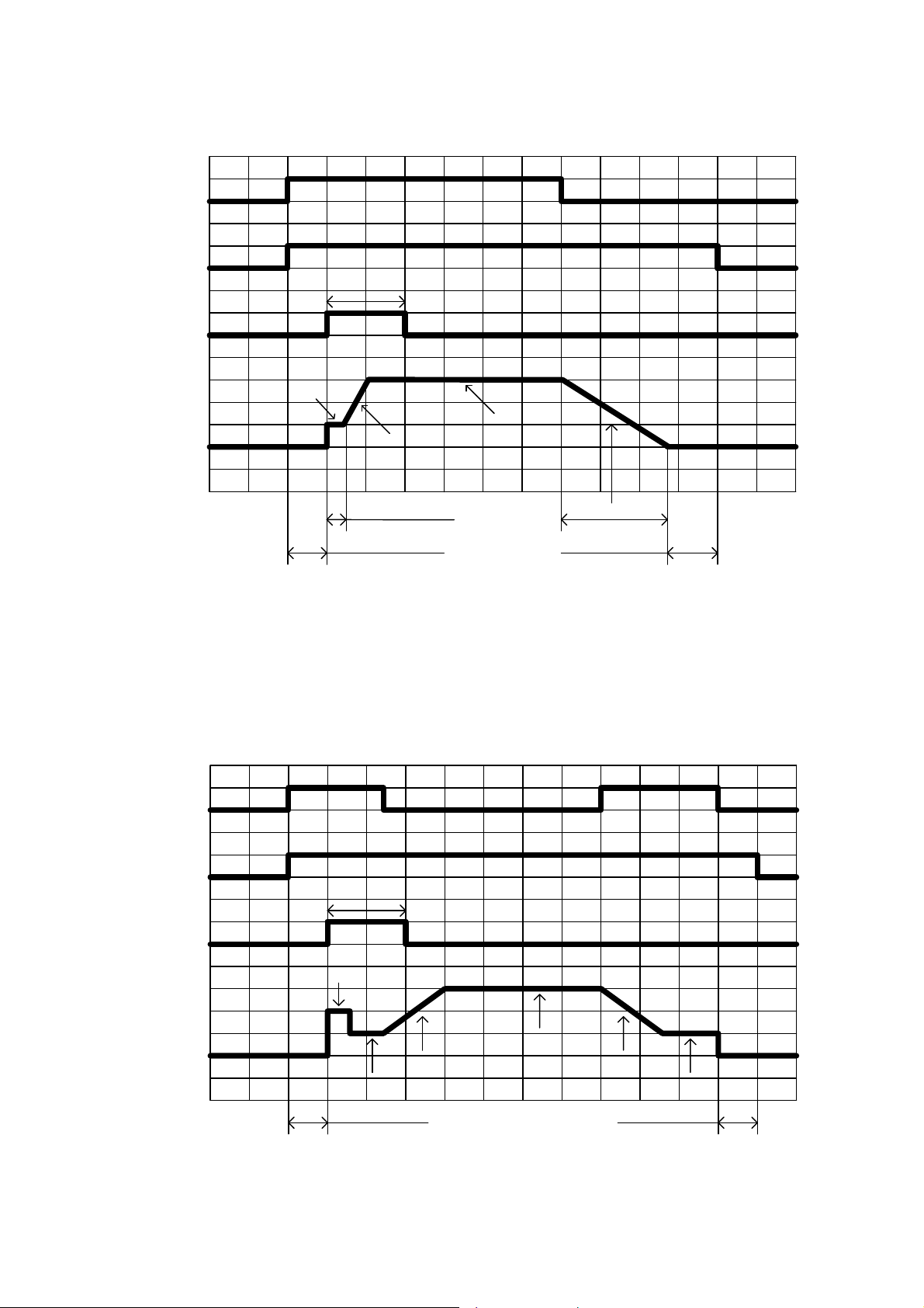
2- Step Mode
Welding
gun switch
Solenoid
value
High-frequency
discharge
Welding
current
ON
OFF
ON
OFF
Arc starting current
OFF
OFF
Discharging time 0.5s, stopped until there is current
Welding current
Up slope
4-Step Mode
Welding
gun switch
Solenoid
value
High-frequency
discharge
OFF
OFF
Arc starting current 0.3s
Pre-flow time
ON
OFF
ON
Arc starting current
Down slope
Post flow time
Diagram of 2-step welding mode
ON
Discharging time 0.5s, stopped until there is current
OFF
OFF
Welding
current
Up slope
Initial current
Pre-flow time
Welding current
Down slope
Diagram of 4-step welding mode
10
Crater current
Post flow time

Repeat
Press torch within 1 second
after releasing, arc die out
Welding
gun switch
Solenoid
value
High-frequency
discharge
Welding
current
OFF
OFF
ON
ON
Arc starting current
Up slope
Initial current
Pre-flow time
ON
OFF
Discharging time 0.5s, stopped until there is current
Up slope
Welding current
Down slope
Crater current
Post flow time
Diagram of Repeat welding mode
ON
OFF
OFF
OFF
11

WIRING DIAGRAM
12

General maintenance
No additional maintenance for fan is required as all parts of the fan are sealed.
If the welding machine is used where there is a lot of dust, the dust may block the
air duct of the welding machine and cause the welding machine to heat up.
Therefore, it is necessary to use dry compressed air to remove the dust inside the
welding machine at set intervals.
Overload protection
The temperature monitoring device in the welding machine, which uses the
thermistor (temperature sensor) to prevent overload or insufficient cooling, can
provide effective protection for the important power devices of the welding
machine. When continuous overload occurs or power device IGBT and fast
recovery diode cannot get adequate heat dissipation, the overheating indicator
light will be on, and the normal output of the welding machine will be stopped.
After these power devices cool down, the overheating indicator light will die out
and the output of the welding machine will automatically return to normal.
The control circuit power supply of the welding machine is designed with latest
integrated power supply chip to ensure that the normal power supply of the
welding machine will not be affected when the network voltage is too low or too
high, and the function of the welding machine will not be affected by the network
voltage. However, excessive power grid input voltage will cause damage to main
circuit capacitors, IGBT, rectifier bridges, fans and other devices.
13

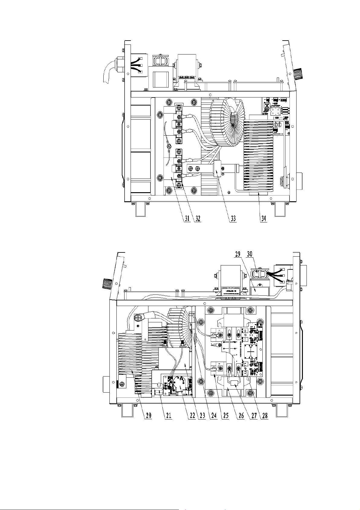
Parts List and Exploded view
No Part Name
1
2 Air outlet nozzle 0061301356
3 Aviation socket (2-core) 0012001047
4 Aviation socket 0012001045
5
6 Display board TIG 400i 0030101983
7 Potentiometer knob (large) 0010603056
8
9 Miniature circuit breaker 0011501003
Welding cable coupling device:
Socket (plate-type)
Welding cable coupling device
Socket
Two-position two-way solenoid
valve
Part
Number
0050804030
0050804024
0011001003
10 Input cables 0030501596
11 Axial flow fan 0011702012
12 Main transformer 0030801632
13 Absorption board 0030101744
14 Filter capacitor 0010222002
15 Three-phase rectifier module 0012103001
16 Power supply detection board 0030101618
17 Control panel 0030101842
18 Power panel 0030101748
19 Control transformer 0060101206
14

No Part Name
20 Coupler 0030801612
21 Arc striking device (spark plug) 0012301292
22 High-frequency arc striking board 0030101746
Part
Number
23
24 Current transformer 0011303019
25 IGBT module 0012101060
26 Filter capacitor 0010222014
27 Discharge resistor component 0030502252
28 Drive board 0030101747
29 Capacitor 0010227001
30 Three-phase input inductance 0031001147
31 Diode absorption board 0030101565
32 Fast recovery diode module 0012102033
33 Hall current sensor 0011301023
High-frequency and high-voltage
capacitor
0010227003
34 Reactor 0030901172
15

16
17

ESAB INDIA LIMITED
Registered and Head Office
13, Industrial Estate, III Main Road
Ambattur, Chennai - 600058
Telephone: + 91 44 42281100
Fax: + 91 44 4228 1107
Email: info@esab.co.in
Web: www.esabindia.com
18
 Loading...