

GB
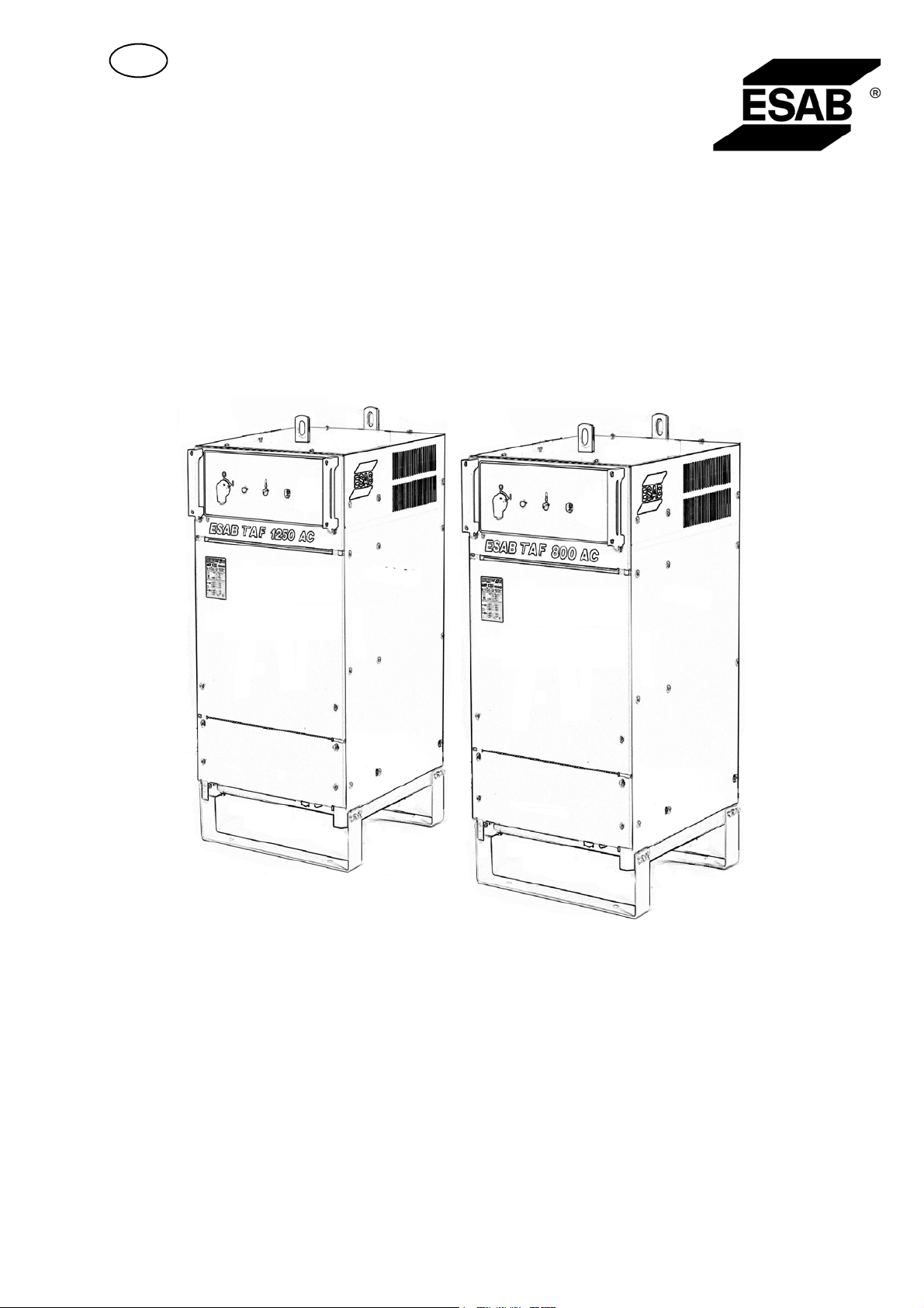
TAF 800/ TAF 1250
AC
Instruction manual
Valid for serial no. 7120456 513 601 GB 2007--04--20

ESAB AB, Welding Equipment, SE--695 81 Laxå, Sweden, declares under sole responsibility that
L
welding power source TAF 800 / TAF 1250AC from serial number 712 (2007 w.12) is designed and
tested in conformity with standard EN 60974--1 and EN 60974--10 in accordance with the conditions in
the directives (2006/95/EC) and (2004/108/EC).
-- -- -- -- -- -- -- -- -- -- -- -- -- -- -- -- -- -- -- -- -- -- -- -- -- -- -- -- -- -- -- -- -- -- -- -- -- -- -- -- -- -- -- -- -- -- -- -- -- -- -- -- -- -- -- -- -- -- -- -- -- -- -- ------------------------------
axå 2007--03--30
Kent Eimbrodt
Global Director
Equipment and Automation
DECLARATION OF CONFORMITY
2

1SAFETY 4...........................................................
2 INTRODUCTION 6...................................................
2.1 General 6..................................................................
2.2 Technical data 6............................................................
3 INSTALLATION 7....................................................
3.1 General 7..................................................................
3.2 Unpacking and location 7.....................................................
3.3 Connections 7..............................................................
3.4 PC board 8.................................................................
4 OPERATION 9.......................................................
4.1 General 9..................................................................
4.2 Controls 9..................................................................
4.3 Start--up 9..................................................................
5 MAINTENANCE 10....................................................
5.1 General 10..................................................................
5.2 Cleaning 10.................................................................
6 ORDERING OF SP ARE P ARTS 10......................................
DIAGRAM 11............................................................
LIST OF COMPONENTS 12...............................................
CONNECTION INSTRUCTION 13..........................................
SPARE PARTS LIST 15...................................................
Rights reserved to alter specifications without notice.
TOCe
-- 3 --

GB
1SAFETY
Users of ESAB welding equipment have the ultimate responsibility for ensuring that anyone who
works on or near the equipment observes all the relevant safety precautions. Safety precautions
must meet the requirements that apply to this type of welding equipment. The following recommendations should be observed in addition to the standard regulations that apply to the workplace.
All work must be carried out by trained personnel well--acquainted with the operation of the welding
equipment. Incorrect operation of the equipment may lead to hazardous situations which can result
in injury to the operator and damage to the equipment.
1. Anyone who uses the welding equipment must be familiar with:
S its operation
S location of emergency stops
S its function
S relevant safety precautions
S welding
2. The operator must ensure that:
S no unauthorised person is stationed within the working area of the equipment when it is
started up.
S no--one is unprotected when the arc is struck
3. The workplace must:
S be suitable for the purpose
S be free from draughts
4. Personal safety equipment
S Always wear recommended personal safety equipment, such as safety glasses, flame--proof
clothing, safety gloves.
S Do not wear loose--fitting items, such as scarves, bracelets, rings, etc., which could become
trapped or cause burns.
5. General precautions
S Make sure the return cable is connected securely.
S Work on high voltage equipment may only be carried out by a qualified electrician.
S Appropriate fire extinquishing equipment must be clearly marked and close at hand.
S Lubrication and maintenance must not be carried out on the equipment during operation.
fja2safe
-- 4 --
GB
WARNING
ARC WELDING AND CUTTING CAN BE INJURIOUS TO YOURSELF AND OTHERS. TAKE PRECAUTIONS WHEN WELDING. ASK FOR YOUR EMPLOYER’S SAFETY PRACTICES WHICH SHOULD BE
BASED ON MANUFACTURERS’ HAZARD DATA.
ELECTRIC SHOCK -- Can kill
S Install and earth the welding unit in accordance with applicable standards.
S Do not touch live electrical parts or electrodes with bare skin, wet gloves or wet clothing.
S Insulate yourself from earth and the workpiece.
S Ensure your working stance is safe.
FUMES AND GASES -- Can be dangerous to health
S Keep your head out of the fumes.
S Use ventilation, extraction at the arc, or both, to take fumes and gases away from your breathing zone
and the general area.
ARC RAYS -- Can injure eyes and burn skin.
S Protect your eyes and body. Use the correct welding screen and filter lens and wear protective
clothing.
S Protect bystanders with suitable screens or curtains.
FIRE HAZARD
S Sparks (spatter) can cause fire. Make sure therefore that there are no inflammable materials nearby.
NOISE -- Excessive noise can damage hearing
S Protect your ears. Use earmuffs or other hearing protection.
S Warn bystanders of the risk.
MALFUNCTION -- Call for expert assistance in the event of malfunction.
READ AND UNDERSTAND THE INSTRUCTION MANUAL BEFORE INSTALLING OR OPERATING.
PROTECT YOURSELF AND OTHERS!
WARNING
This product is intended for industrial use. In a domestic environment this
product may cause radio interference. It is the user’s responsibility to take
adequate precautions.
WARNING!
Read and understand the instruction manual
before installing or operating.
Do not dispose of electrical equipment together with normal waste!
In observance of European Directive 2002/96/EC on Waste Electrical and Electronic
Equipment and its implementation in accordance with national law, electrical equipment
that has reached the end of its life must be collected separately and returned to an
environmentally compatible recycling facility. As the owner of the equipment, you should
get information on approved collection systems from our local representative.
By applying this European Directive you will improve the environment and human health!
fja2safe
-- 5 --

GB
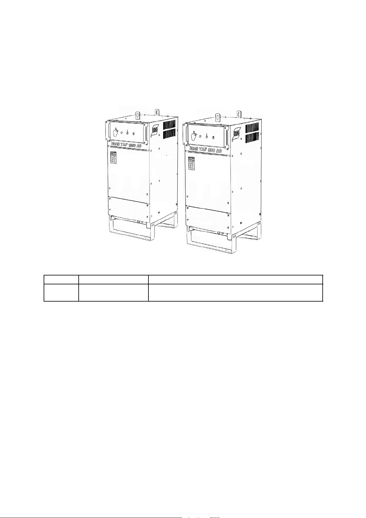
2 INTRODUCTION
2.1 General
TAF 800/1250 are remote--controlled, two-- phase AC welding power sources
designed for high--throughput, mechanised submerged --arc welding (SAW).
They should always be used in conjunction with ESAB’s control box
A2--A6 Process Controller (PEH).
The welding power source converts, via a thyristor bridge--rectifier, the secondary
voltage’s sine wave to a square wave with excellent arc ignition and welding
characteristics. They are fan cooled and are overload protected by a thermal
cut--out. Re-- setting takes place automatically as soon as the temperature has
reduced to an acceptable level.
The welding power source and control box are connected together via a two--wire
bus, which makes it possible to control the welding process very precisely.
Adjustment of the welding power source can be carried out from the front panel of
the control box, where all the welding parameters can be adjusted by the operator.
The operation of the welding power source is controlled and monitored completely
by the control box, from which the start and stop characteristics can be set.
The pre--set welding parameters can be monitored while welding is in progress.
For more detailed information regarding the settings and the working mode of the
welding power source, please refer to the A2--A6 Process Controller (PEH)
instruction manual.
2.2 Technical data
TAF 800 TAF 1250
Voltage 346/400/415/ 500 V, 1μ50 Hz
400/440/550 V, 1μ60 Hz
Permissible load at:
100 % duty cycle
60 % duty cycle
Setting range 300 A/32 V -- 800 A/44 V 400 A/36 V -- 1250 A/44 V
No--load voltage 71 V 71 V
No--load power 230 W 230 W
Effiency 0,86 0.86
Power factor 0,75 0,76
Weight 495 kg 608 kg
Dimensions L x W x H 774 x 598 x 1228 774 x 598 x 1228
Enclosure class IP 23 IP 23
800 A/44 V
1000 A/44 V
346/400/415/500 V, 1μ50 Hz
400/440/550 V, 1μ60 Hz
1250 A /44 V
1500 A/44 V
Application class
Enclosure class
The IP code indicates the enclosure class, i. e. the degree of protection against penetration by solid
objects or water. Equipment marked IP 23 is designed for indoor and outdoor use.
Application class
The symbol indicates that the power source is designed for use in areas with increased
electrical hazard.
fja2d1ea
-- 6 --
GB
3 INSTALLATION
3.1 General
The installation must be executed by a professional.
3.2 Unpacking and location
WARNING -- TIPPING RISK!
Fasten the equipment -- particularly if the ground is uneven or sloping.
S Place the welding power source on a level foundation.
S Make sure there is nothing to prevent the cooling.
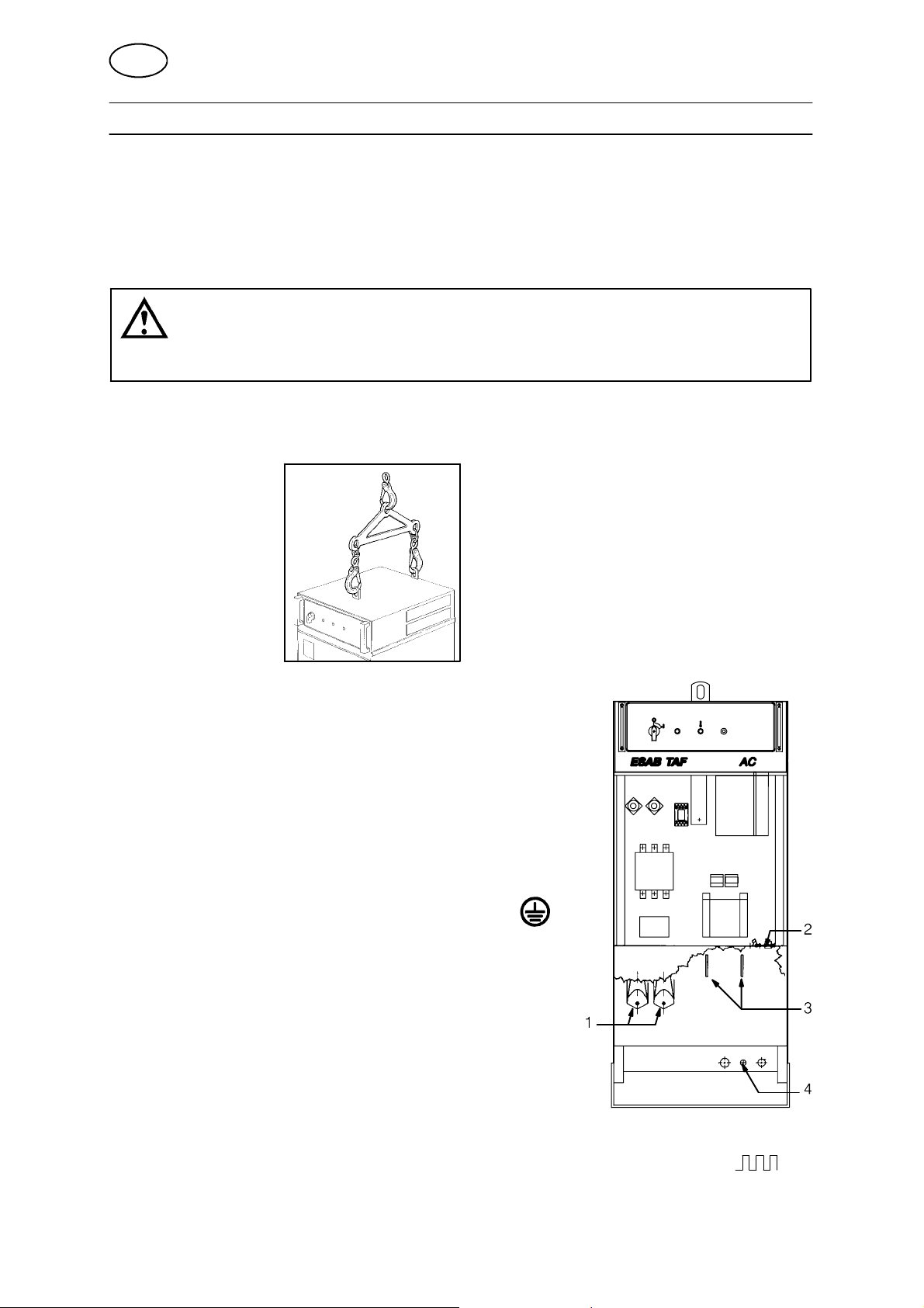
Lifting instructions
3.3 Connections
S On delivery the welding power source is connected
for 400 V. For other supply voltage, switch over to
the desired voltage on the main transformer and the
control transformer according to the connection
instructions on page 13.
S Make sure the mains cable has the right sectional area
and fuse it with an adequate fuse according to
applicable local directions (see table on page 8).
S Connect the earth cable to the screw marked .
S Tighten the cable support (1).
S Connect the mains cable to the main terminal
blocks L1 and L3.
S Connect the control cable between the TAF
welding power source and the control unit to the
28--pole contact (2) inside the welding power
source.
S Connect 1--pin socket measure cable (4)tothe
work piece.
S Connect a suitable welding and return cable to the contacts (3) marked on
the front of the power source.
fja2i1ea
-- 7 --

GB
Mains connectio n
TAF 800 50 Hz
Voltage (V) 346 400 / 415 500 400/ 440 550
Current (A)
I
max
1
I
eff
1
Cablearea(mm2) 2x70+35 2x70+35 2x50+35 2x70+35 2x50+35
Fuse, slow (A) 160 160 125 160 125
TAF 1250
Voltage (V) 346 400 / 415 500 400 / 440 550
Current (A)
I
max
1
I
eff
1
Cablearea(mm2) 2x(2x70+35) 2x(2x70+35) 2x95+50 2x(2x70+35) 2x95+50
Fuse, slow (A) 250 200 200 200 200
184
145
299
249
160
127
50 Hz 60 Hz
254
212
129
104
205
170
160
127
254
212
60 Hz
129
104
205
170
3.4 PC board
The PC board (AP1) has two DIP switches (SW1 and SW2) which are preset on
delivery. The settings are not to be changed.
When spare parts are installed the settings of the DIP switches must be checked
(and set, if necessary) before fitting the PC board into the welding power source.
3.4.1 DIP switch SW1
To make the communication with the
A2--A6 Process Controller work,
DIP switch 1 (SW1) must be set.
Setting of DIP switch SW1:
S Set pole 6 to “OFF” position and all
other poles to “ON”.
3.4.2 DIP switch SW2
DIP switch 2 (SW2) must be set in order to
inform the A2--A6 process controller about the
rating of the power source that is connected.
Setting of DIP switch SW2:
S TAF 800
Set pole 1 to “OFF“ position and all other poles to “ON“.
S TAF 1250
Set pole 2 to “OFF” position and all other poles
to “ON”.
Welding power source program
The welding power source program is stored in the flash memory IC 6.
The capsule is fitted in a holder and is replaceable.
fja2i1ea
-- 8 --
GB
4 OPERATION
4.1 General
General safety regulations for the handling of the equipment can be found on
page 4. Read through before you start using the equipment!
Note! Never use the welding power source without side plates.
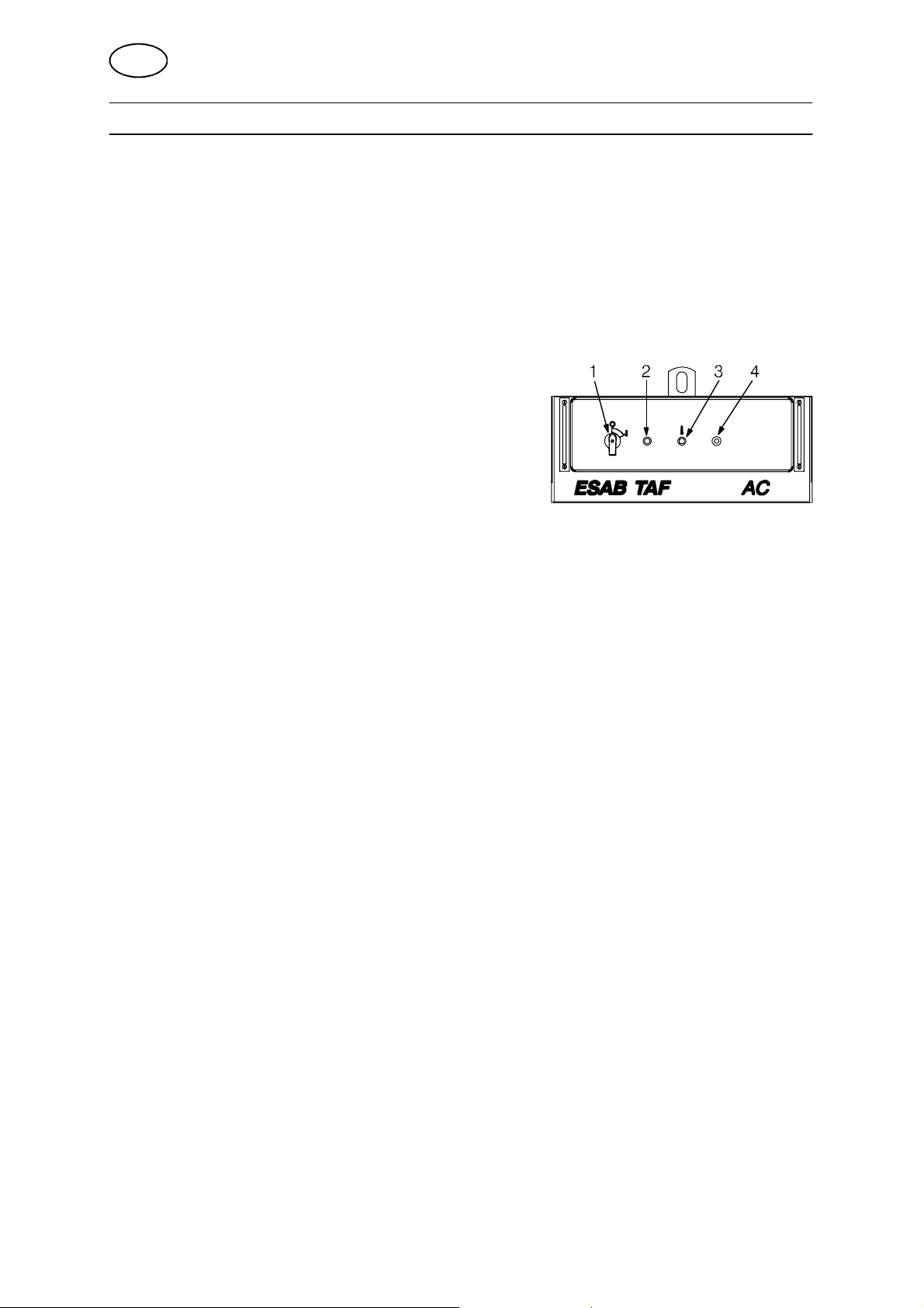
4.2 Controls
The front panel contains:
S Main switch (1) breaking the incoming mains
voltage for the welding power source.
S White Indicating lamp (2) showing that the
main switch is activated.
S Yellow indicating lamp (3) showing that the
thermal protection has entered into action due to
overheating in the transformer. The lamp is reset
when the temperature has gone down to an
acceptable level.
S Pushbutton (4) for the r esetting of automatic fuse FU1 for 42 V supply voltage.
4.3 Start--up
S Connect the return cable to the work piece.
S Set the main switch (1) to position “I“.
The white indicating lamp (2) goes on and the fan starts.
S Set the welding parameters and start welding by way of the control box
(see the A2--A6 Process Controller 0443 745 xxx instruction manual).
fja2o1ea
-- 9 --
GB
5 MAINTENANCE
5.1 General
Note:
All warranty undertakings given by the supplier cease to apply if the customer
attempts to rectify any faults on the machine during the warranty period.
5.2 Cleaning
S Clean the welding power source as necessary.
Dry compressed air is recommended for the purpose.
WARNING! Blocked air inlets or outlets will lead to overheating.
Note:
In order to ensure safe operation of the contactor, keep the magnetic parts clean.
If the contactor has to be cleaned it must be taken apart, and all the pieces be
cleaned.
Alternatively, the contactor can be replaced.
WARNING!
Never use compressed air to clean the contactor without first taking it apart
completely.
6 ORDERING OF SP ARE PARTS
TAF 800/ TAF 1250 is designed and tested in accordance with the international and European standards IEC/EN 60974--1 and IEC/EN 60974--10.
It is the obligation of the service unit which has carried out the service or repair work
to make sure that the product still conforms to the said standard.
Spare parts are ordered through your nearest ESAB representative, see back cover.
When ordering spare parts, please state machine type and number as well as designation and spare part number as shown in the spare parts list on page 15.
This will simplify dispatch and ensure you get the right part.
fja2m1ea
-- 1 0 --
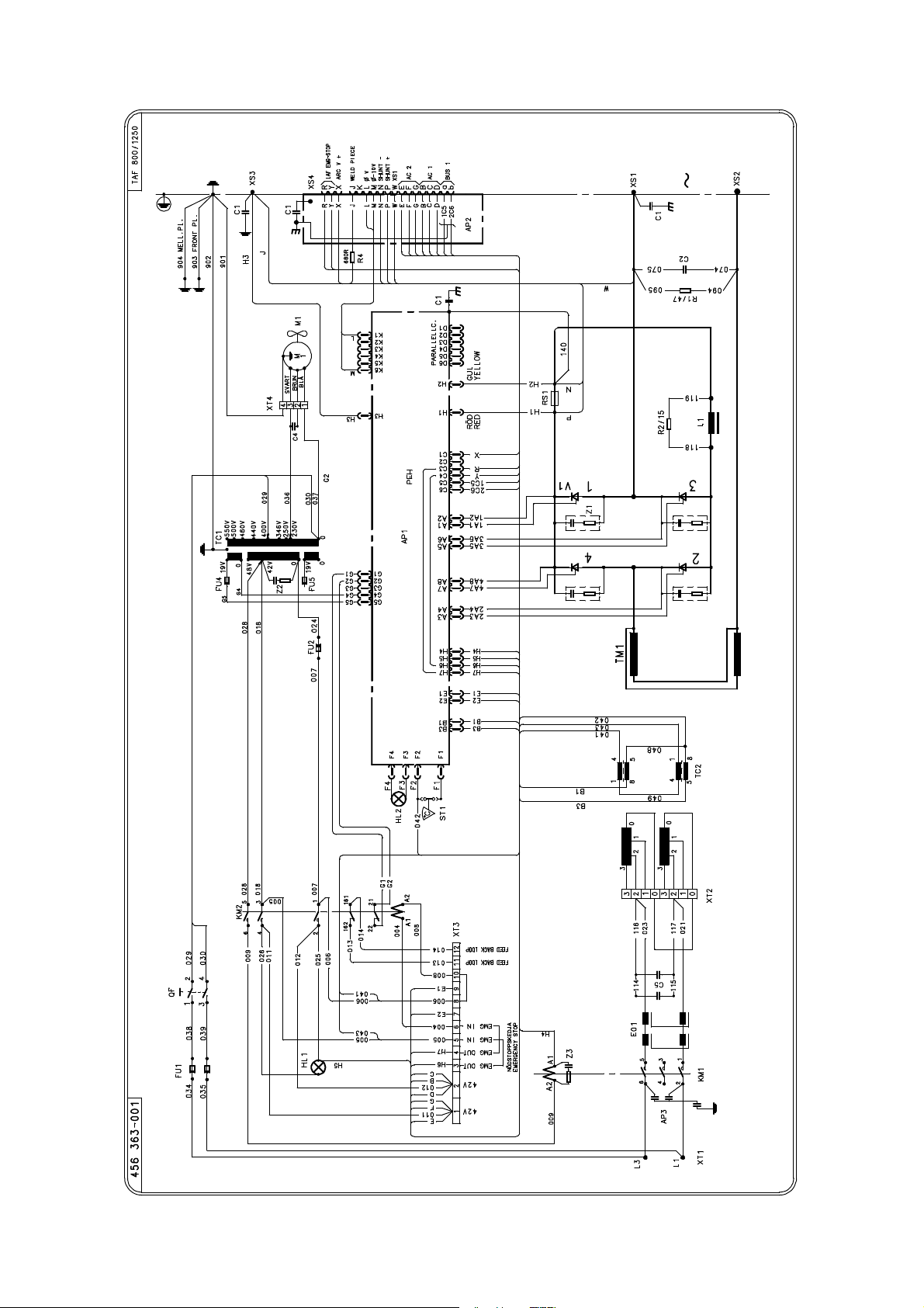
Diagram
fja2e12a
-- 1 1 --

List of components
C = Component designation in the circuit diagram
C Denomination C Denomination
AP1 Circuit board
AP2 Circuit board EMC--filter
AP3 Circuit board (disturbance elimin-
ation)
C1 Capacitor
C2 Capacitor
C4 Capacitor
C5 Capacitor
EO1 Ferrite core
FU1 Fuse
FU2 Fuse
HL1 Indicator lamp, white
HL2 Indicator lamp yellow
KM1 Contactor
KM2 Contactor
L1 Inductor
M1 Fan
QF Main switch (black)
R1 Power resistor
R2 Power resistor
RS1 Shunt
ST1 Thermal relay
TC1 Control transformer
TC2 Control transformer
TM1 Transformer
V1 Thyristor
XS3 Screw terminal
XS4 Burndy socket
XT1 Connection block
XT2 Connection block
XT3 Connection block
XT4 Connection block
Z1, Z2 Contact protection
Z3 Contact protection
fja2e12a
-- 1 2 --

Connection instruction
fja2c12a
-- 1 3 --

sida
-- 1 4 --
Spare parts list
TAF 800/ TAF 1250 AC
Edition 2007--04--02
Ordering no. Denomination Notes
0456 325 880 Welding power source TAF 800
0456 326 880 Welding power source TAF 1250
Abbreviations used in the spare parts list:
C = Component designation in the circuit diagram
fja2s11a
-- 1 5 --

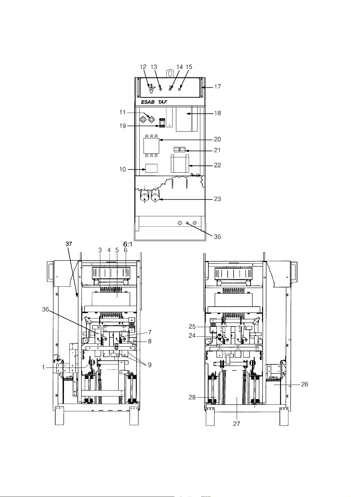
Item
Qty
no.
TAF 800
1 2 2 0442 719 880 Connection block
3 1 1 0318 042 882 Inductor coil
4 1
5 1 0442 763 880 Inductor L1
6 1 1 0460 004 880 Fan complete
6:1 1 1 0460 294 880 Fan M1
7 6 6 0041 051 606 Contact protection Z1--Z3
8 2
9 4
10 1 1 0486 178 880 Circuit board EMC--filter AP2
11 2 2 0567 200 610 Fuse 16 A FU1
12 1 1 0320 746 002 Main switch Black QF
13 1 1 0192 576 004 Lamp On/Off HL1
14 1 1 0192 576 303 Indicator lamp Yellow HL2
15 1 1 0193 586 104 Automatic fuse 20 A FU2
17 2 2 0156 388 001 Handle
18 1 1 0486 376 880 Circuit board AP1
19 1 1 0805 586 131 Contactor KM2
20 1
21 2 2 0319 828 001 Control transformer TC2
22 1 1 0460 092 001 Control transformer TC1
23 1 1 0158 115 880 Cable inlet
24 1 1 0319 445 001 Thermal relay ST1
25 1 1 0551 203 080 Shunt RS1
26 1 1 0442 846 001 Capacitor C5
27 1
28 1
35 1 1 0523300201 Positive terminal
36 1 1 0319445001 Thermostat
37 0191 085 104 Capacitor C4
Qty
TAF 1250
Ordering no. Denomination Notes C
0456 325 880 Welding power source TAF 800
0456 326 880 Welding power source TAF 1250
0442 906 880
0442 906 881
1
1 0442 945 880 Inductor L1
0442 972 001
0321 427 001
2
0442 993 880
0443 065 880
4
0442 849 880
0442 849 881
1
0457 934 880
0457 935 880
1
0442 717 884
0442 717 885
1
Inductor coil
Inductor coil
Thyristor
Thyristor
Thyristor bridge
Thyristor bridge
Contactor
Contactor
Transformer coil
Transformer coil
Transformer
Transformer
V1
V1
KM1
KM1
TM1
f456325s
1 1 0486178880 Circuit board (disturb-
ance eliminator)
-- 1 6 --
AP3
TAF 800/1250 AC
f456325s
-- 1 7 --
ESAB subsidiaries and representative offices
Europe
AUSTRIA
ESAB Ges.m.b.H
Vienna--Liesing
Tel: +43 1 888 25 11
Fax: +43 1 888 25 11 85
BELGIUM
S.A. ESAB N.V.
Brussels
Tel: +32 2 745 11 00
Fax: +32 2 745 11 28
THE CZECH REPUBLIC
ESAB VAMBERK s.r.o.
Vamberk
Tel: +420 2 819 40 885
Fax: +420 2 819 40 120
DENMARK
Aktieselskabet ESAB
Herlev
Tel:+4536300111
Fax:+4536304003
FINLAND
ESAB Oy
Helsinki
Tel: +358 9 547 761
Fax: +358 9 547 77 71
FRANCE
ESAB France S.A.
Cergy Pontoise
Tel:+33130755500
Fax:+33130755524
GERMANY
ESAB GmbH
Solingen
Tel: +49 212 298 0
Fax: +49 212 298 218
GREAT BRITAIN
ESAB Group (UK) Ltd
Waltham Cross
Tel: +44 1992 76 85 15
Fax: +44 1992 71 58 03
ESAB Automation Ltd
Andover
Tel: +44 1264 33 22 33
Fax: +44 1264 33 20 74
HUNGARY
ESAB Kft
Budapest
Tel:+3612044182
Fax:+3612044186
ITALY
ESAB Saldatura S.p.A.
Mesero (Mi)
Tel:+3902979681
Fax:+390297289181
THE NETHERLANDS
ESAB Nederland B.V.
Utrecht
Tel: +31 30 2485 377
Fax: +31 30 2485 260
NORWAY
AS ESAB
Larvik
Tel:+4733121000
Fax:+4733115203
POLAND
ESAB Sp.zo.o.
Katowice
Tel: +48 32 351 11 00
Fax: +48 32 351 11 20
PORTUGAL
ESAB Lda
Lisbon
Tel: +351 8 310 960
Fax: +351 1 859 1277
SLOVAKIA
ESAB Slovakia s.r.o.
Bratislava
Tel:+421744882426
Fax:+421744888741
SPAIN
ESAB Ibérica S.A.
Alcalá de Henares (MADRID)
Tel: +34 91 878 3600
Fax: +34 91 802 3461
SWEDEN
ESAB Sverige AB
Gothenburg
Tel:+4631509500
Fax:+4631509222
ESAB international AB
Gothenburg
Tel:+4631509000
Fax:+4631509360
SWITZERLAND
ESAB AG
Dietikon
Tel: +41 1 741 25 25
Fax: +41 1 740 30 55
North and South America
ARGENTINA
CONARCO
Buenos Aires
Tel: +54 11 4 753 4039
Fax: +54 11 4 753 6313
BRAZIL
ESAB S.A.
Contagem--MG
Tel: +55 31 2191 4333
Fax: +55 31 2191 4440
CANADA
ESAB Group Canada Inc.
Missisauga, Ontario
Tel: +1 905 670 02 20
Fax: +1 905 670 48 79
MEXICO
ESAB Mexico S.A.
Monterrey
Tel: +52 8 350 5959
Fax: +52 8 350 7554
USA
ESAB Welding & Cutting Products
Florence, SC
Tel: +1 843 669 44 11
Fax: +1 843 664 57 48
Asia/Pacific
CHINA
Shanghai ESAB A/P
Shanghai
Tel: +86 21 5308 9922
Fax: +86 21 6566 6622
INDIA
ESAB India Ltd
Calcutta
Tel: +91 33 478 45 17
Fax: +91 33 468 18 80
INDONESIA
P.T. ESABindo Pratama
Jakarta
Tel: +62 21 460 0188
Fax: +62 21 461 2929
JAPAN
ESAB Japan
Tokyo
Tel: +81 3 5296 7371
Fax:+81352968080
MALAYSIA
ESAB (Malaysia) Snd Bhd
Selangor
Tel: +60 3 8027 9869
Fax:+60380274754
SINGAPORE
ESAB Asia/Pacific Pte Ltd
Singapore
Tel:+6568614322
Fax: +65 6861 31 95
SOUTH KOREA
ESAB SeAH Corporation
Kyungnam
Tel: +82 55 269 8170
Fax: +82 55 289 8864
UNITED ARAB EMIRATES
ESAB Middle East FZE
Dubai
Tel: +971 4 887 21 11
Fax: +971 4 887 22 63
Representative offices
BULGARIA
ESAB Representative Office
Sofia
Tel/Fax: +359 2 974 42 88
EGYPT
ESAB Egypt
Dokki--Cairo
Tel: +20 2 390 96 69
Fax: +20 2 393 32 13
ROMANIA
ESAB Representative Office
Bucharest
Tel/Fax: +40 1 322 36 74
RUSSIA
LLC ESAB
Moscow
Tel: +7 095 543 9281
Fax: +7 095 543 9280
LLC ESAB
St Petersburg
Tel: +7 812 336 7080
Fax: +7 812 336 7060
Distributors
For addresses and phone
numbers to our distributors in
other countries, please visit our
home page
www.esab.com
ESAB AB
SE-- 695 81 LAXÅ
SWEDEN
Phone +46 584 81 000
www.esab.com
061127
 Loading...