

Page 1

INSTRUCTION MANUAL for the
ESAB SmartFlow
PLASMA CUTTING SYSTEM
F14-129
August, 1997
411 South Ebenezer Road
Florence, SC 29501-0545
Page 2

The equipment described in this manual is
potentially hazardous. Use caution in installing,
operating, and maintaining this equipment.
The purchaser is solely responsible for the
safe operation and use of all products
purchased, including compliance with OSHA
and other government standards. ESAB
Cutting Systems has no liability for personal
injury or other damage arising out of the use
of any product manufactured or sold by ESAB.
See standard ESAB terms and conditions of
sale for a specific statement of ESAB’s
responsibilities and limitations on its liability.
ESAB Cutting Systems is not responsible for
any errors that may appear in this document.
The information in this document is subject to
change without notice.
This manual is ESAB Part Number F14129.
This manual is for the convenience and use of the
cutting machine purchaser. It is not a contract or
other obligation on the part of ESAB Cutting
Systems.
ESAB Cutting Systems, 1997
Printed In USA
Page 3

This manual is not a safety guide for the use of the
equipment. The purchaser, through its own
judgment and safety procedures, is solely
responsible for safe operation. However, in
presenting the information in this manual, a system
of advisory notes has been provided to point out
specific information that will be helpful in the safe
and proper operation of the equipment.
The method used to identify these notes and the
purpose for each are as follows:
An operational procedure or background
information that aids the operator in efficient use
of the system and in performing maintenance, or
information that requires additional emphasis.
An operational procedure which, if not
properly followed, may cause damage to the
system.
An operational procedure that, if not
properly followed, may cause injury to the
operator or others in the operating area.
Page 4

Page 5

SmartFlow Plasma System
Preface
This manual applies only to the ESAB SmartFlow
Plasma Cutting System using the Vision CNC and
ASIOB I/O Structure. For plasma systems with
alternate hardware, refer to the appropriate
manual.
The ESAB SmartFlow Plasma Cutting System is
an advanced, numerically controlled plasma
cutting package manufactured by ESAB Cutting
Systems of Florence, South Carolina. This
system is designed to be installed on an ESAB
Gantry Shape Cutting Machine. It is designed to
provide years of dependable, accurate, repeatable
part cutting, with a high degr ee of reliability, ease
of service and ease of operation.
There are various optional configurations possible
with the SmartFlow system. For completeness, all
of these options are described in this manual.
However, not all options or capabilit ies described
in this manual are present on all machines. In
addition, more capabilities and features may be
added in the future, which are not covered in this
manual. ESAB Cutting Systems reserves the
right to change or add features and capabilities
without notice.
Before operating the system, one should become
familiar with this manual in its entirety, wit h special
attention to the SAFETY section.
Page 6

Contents
1 Safety...................................................................................................1
2 Introduction...........................................................................................5
3 Installation ............................................................................................ 9
1.1 Introduction...............................................................................1
1.2 General Safety Information.......................................................2
1.3 Plasma Marking Precautions.....................................................3
1.3.1 Electrical Shock Prevention...........................................3
1.3.2 Eye Safety..................................................................... 3
1.4 Skin Safety................................................................................ 4
1.5 Electrical Grounding.................................................................. 4
2.1 Overview................................................................................... 5
2.2 System Description...................................................................5
2.2.1 Component Description.................................................5
2.2.2 SmartFlow System with PT-15XL Torch........................6
2.2.3 SmartFlow System with PT-19XL Torch........................7
3.1 Requirements............................................................................9
3.1.1 Gas Supply Requirements.............................................9
3.1.2 Water Supply Requirements.......................................... 9
3.1.3 Deionized Water Requirements (PT-15XL).................... 9
3.1.4 Electrical Input Requirements........................................ 9
3.2 Connections............................................................................ 10
3.2.1 Hose and Cable Connections......................................10
3.2.2 Pilot Arc Cable Connections........................................10
3.3 Supply Setup........................................................................... 11
3.3.1 Gas Supply Pressures................................................. 11
3.3.2 Cut Water Supply Pressure.........................................12
3.3.3 Cut Water Pump Setup................................................ 12
4 Setup..................................................................................................13
4.1 Introduction.............................................................................13
4.2 Prerequisites........................................................................... 13
4.3 Gas Regulator Setup .............................................................. 14
4.3.1 Gas Regulator Panel Setup......................................... 14
4.3.2 Shield Air Regulator..................................................... 15
4.4 CNC Setup.............................................................................. 16
Page 7

SmartFlow Plasma System
5 Process Data ......................................................................................19
6 Maintenance .......................................................................................25
6.1 Routine Maintenance...............................................................25
6.2 Technical Description..............................................................26
6.2.1 Gas Control..................................................................26
6.2.2 Cut Water Control........................................................28
6.2.3 Secondary Shield Gas Control.....................................30
6.2.4 Cooling Water Circuit...................................................32
6.3 Maintenance Procedures.........................................................34
6.3.1 Introduction..................................................................34
6.3.2 Gas Pressure Switch ...................................................34
6.3.3 Water Pressure Switch ................................................36
6.3.4 Gas Regulator..............................................................37
6.3.5 Interlock Switch............................................................38
6.3.6 Cut Water Pressure .....................................................40
6.3.7 Gas Filters ...................................................................41
6.3.8 Gas Proportional Valve................................................41
6.3.9 Water Proportional Valve.............................................42
6.3.10 Cooling Water Flow Switch ........................................42
6.4 Schematics..............................................................................43
6.5 Troubleshooting.......................................................................47
7 Replacement Parts..............................................................................49
7.1 General Information.................................................................49
7.2 Ordering Information ...............................................................50
7.3 SmartFlow Plasma Flow Control..............................................51
7.3.1 Arc Starter Box Assembly............................................57
7.3.2 Flow Tube Box Assembly.............................................59
Page 8

Page 9

1 Safety
1.1 Introduction
SmartFlow Plasma System
ESAB plasma cutting products are designed to
provide both safety and efficiency in operation.
However, sensible attention to operating
procedures, precautions, and safe practices is
necessary to achieve a full measure of safety.
Whether an individual is involved with operation,
servicing, or as an observer, compliance with
established precautions and safe practices must be
accomplished. Failure to observe certain
precautions could result in serious injury to
personnel or severe damage to the equipment.
The following precautions are specific guidelines
applicable to the plasma cutting process. More
general precautions are presented in the instruction
literature pertaining to the cutting machine.
Safety Page 1
Page 10

Section 1
1.2 General Safety Information
All personnel, materials, and equipment not
involved in the production process must be
kept clear of the entire system area. Only
qualified personnel should be allowed to
operate or service the equipment.
Read entirely through a procedure to become
familiar with the task before operating or
performing maintenance on any part of the
system. Special attention must be given to all
WARNINGS, CAUTIONS, and NOTES which
provide essential information regarding
personnel safety and/or possible damage to
equipment.
All safety precautions relevant to electrical
equipment and the process operations must
be strictly observed by all who have
responsibility or access to the system. DO
NOT touch the plasma marking torch during
operation. Do not operate any part of the
system with any of the protective covers
removed or electrical component boxes open.
Refer to all safety publicati ons made available
by your company.
Fence off the entire work cell to prevent
personnel from passing through the area or
standing within the working envelope of the
equipment. Post appropriate CAUTION signs
at every entrance to the work cell area.
Page 2 Safety
Page 11

1.3 Plasma Cutting Precautions
1.3.1 Electrical Shock Prevention
SmartFlow Plasma System
The plasma arc cutting process employs high
voltages. High voltage can kill. Do NOT touch the
marking torch, cutting table or cable connections
during the plasma cutting process.
Electrical Shock Can Kill You!
• Always turn off power to the plasma power
supplies before touching or servicing a plasma
marking torch.
• Always turn off power to the plasma power
supplies before opening or servicing the plasma
power supply or interface box.
1.3.2 Eye Safety
• Do not touch live electrical parts.
• Keep all panels and covers in place when the
machine is connected to a power source.
• Insulate yourself from the workpiece and
electrical ground: wear insulating gloves, shoes
and clothing.
• Keep gloves, shoes, clothing, work area, and
this equipment dry.
Arc rays can injure eyes and burn skin.
To protect your eyes from burns caused by high
intensity ultraviolet light, sparks and hot metal :
• Do not look at the arc.
• Wear correct eye protection. Wear dark safety
glasses or goggles with side shields.
• Replace glasses/goggles when the lenses
become pitted or broken
• Warn other people in the area not to look
directly at the arc unless they wear appropriate
Safety Page 3
Page 12

Section 1
1.4 Skin Safety
safety glasses.
• Prepare the cutting area in a manner that
reduces the reflection and transmission of
ultraviolet light:
• Paint walls and other surfaces with dark colors
to reduce reflections.
• Install protective screens or curtains to reduce
ultraviolet transmission.
To protect skin against burns caused by high
intensity ultraviolet light, sparks and hot metal:
• Wear protective clothing:
1.5 Electrical Grounding
• Wear gauntlet gloves.
• Wear flame-retardant clothing which covers all
exposed areas.
• Wear cuffless trousers to prevent entry of
sparks and slag.
• Do not touch the torch when it is about to sta rt
or while marking. After marking, allow time for
the front of the torch to cool.
Electrical grounding is imperative for proper
machine operation as well as for SAFETY.
All ESAB Shape Cutting Machines must have a
good electrical connection to earth ground.
Page 4 Safety
Page 13

2 Introduction
2.1 Overview
2.2 System Description
SmartFlow Plasma System
The SmartFlow Plasma Cutting System is a
streamlined, high performance plasma cutting
package designed for use exclusively with the
ESAB Vision CNC. ESAB’s exclusive SmartFlow
technology integrates gas and water control into
the cutting machine CNC.
Using a system of proportional valves driven by
CNC outputs, this system dramatically reduces the
amount of plumbing hardware necessary to c ontrol
the plasma torch. Operation is simplified by putting
control of gas and water flow rates on scre en at the
Vision CNC.
2.2.1 Component Description
The SmartFlow system components include a
plumbing box, a flow tube box, and a regulator
panel. The plumbing box contains the p roportional
valves and plumbing necessary to control gas and
water flows. The flow tube box contains three flow
indicator tubes, which provide visual feedback to
the machine operator of the actual gas and water
flow rates. The regulator panel provides pressure
regulation for the incoming gas and water supplies.
When the PT-15XL water injection torch is used,
the complete SmartFlow cutting system also
includes a plasma power supply, a recirculating
water cooler, a cut water pump, an air curtain
control, and the Vision CNC. If the PT-19XL dry
torch is used, then the cut water supply system and
air curtain control are omitted.
The following pages show the complete system
overviews.
Introduction Page 5
Page 14
Section 2
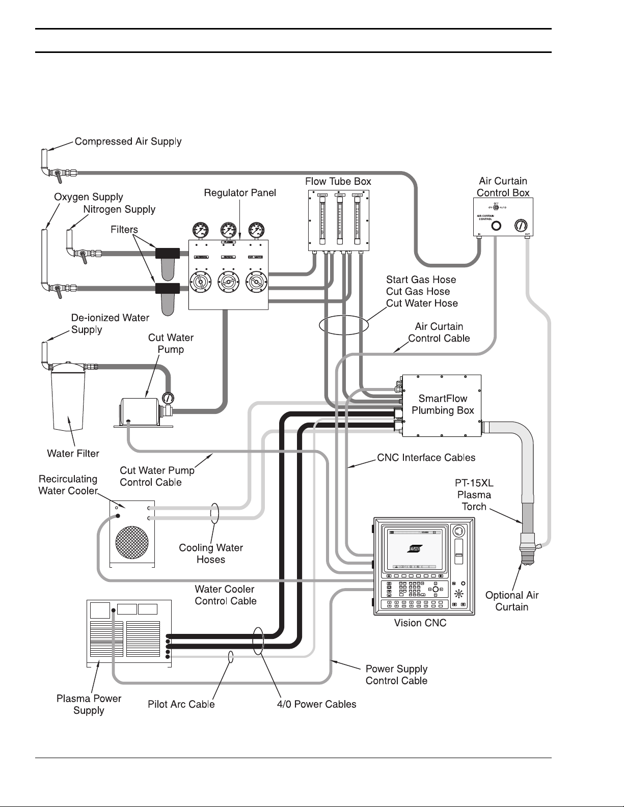
2.2.2 SmartFlow System with PT-15XL Torch
The illustration below shows the SmartFlow system
when a PT-15XL water injection torch is used.
Page 6 Introduction
Page 15

2.2.3 SmartFlow System with PT-19XL Torch
SmartFlow Plasma System
The illustration below shows the SmartFlow system
when the PT-19XL dry torch is used. In this system
the cut water supply equipment is omitted, a
secondary shield is used instead of an air curtain,
and shield gas is controlled through the SmartFlow
plumbing Box.
Introduction Page 7
Page 16

Section 2
Page 8 Introduction
Page 17

3 Installation
3.1 Requirements
3.1.1 Gas Supply Requirements
SmartFlow Plasma System
Nitrogen 125 PSI (1/2 NPT)
99.999% Pure
Oxygen 125 PSI (1/2 NPT)
99.999% Pure
Compressed Air (PT-19XL
with Secondary Shield only)
3.1.2 Water Supply Requirements
Cooling Water 120 PSI
3.1.3 Deionized Water Requirements (PT-15XL)
Deionized Water 35 PSI (1/2 NPT)
3.1.4 Electrical Input Requirements
Voltage Supply +24 VDC for proportional valves,
100 PSI (1/2 NPT)
Clean, Dry, Filtered to 5 micron.
1.5 GPM
> 200,000 Ω
.5 GPM for up to 600 Amp cutting
1.5 GPM for 1000 Amp cutting
flow and pressure switches.
+15 VDC for pressure switch.
Voltage Signals 120 VAC input to start gas
solenoid valve.
120 VAC input to cut gas solenoid
valve.
120 VAC input to Arc Starter.
0 - 10 Volt DC inputs to
proportional valves.
Installation Page 9
Page 18

Section 3
3.2 Connections
3.2.1 Hose and Cable Connections
The SmartFlow Plasma Cutting package is
designed to be interfaced with the ESAB Vision
CNC and any ESP Plasma Power Supply.
Connections to the plumbing box are illustrated
here. A color code is used on the hose
connections between the flow tube box and the
plumbing box:
Green = Oxygen
Yellow = Nitrogen
White = Cooling Water
Blue = Cut Water
The Control Cable Entrance plate can be removed,
allowing the control cables to be installed or
removed without any re-wiring at the plug terminals.
3.2.2 Pilot Arc Cable Connections
The Options Cover is replaced by an additional
hose adaptor when the PT-19XL is used with a
Secondary Shield kit, allowing the plumbing box to
control shield gas flow. The Options Cover also
allows space for a third power cable connector for
PT-15XL installations cutting at 1000 Amps.
The Pilot Arc Cables must be connected properly
to the insulated high voltage terminals at the Arc
Starter Box, as shown here.
The Pilot Arc Ground Cable (from the plasma power
supply) is connected to TB1, toward the open side
of the plumbing box.
The Pilot Arc Torch Cable (from the torch leads) is
connected to TB3, toward the back of the
plumbing box.
TB2 is connected to the Busbar, internal to the
plumbing box.
Page 10 Installation
Page 19

3.3 Supply Setup
3.3.1 Gas Supply Pressures
SmartFlow Plasma System
The Oxygen and Nitrogen gases may be supplied
from bottles or bulk tanks. The supplies to the
cutting machine must be controlled with the proper
type of regulator. Adjust these pressures as
follows:
Oxygen
Set the Oxygen pressure to 140 PSI while the gas
is flowing.
Nitrogen
Set the Nitrogen pressure to 140 PSI while the gas
is flowing.
Installation Page 11
Page 20

Section 3
3.3.2 Cut Water Supply Pressure
Installations using the PT-15XL water injection torch
require a supply of deionized water. This water
must be regulated to a minimum of 30 PSI to
prevent the cut water pump from cavitating.
The cut water regulator is located on the Plasma
Regulator Panel. Set the Cut Water pressure to 30
PSI while the water is flowing.
3.3.3 Cut Water Pump Setup
Installations using the PT-15XL water injection torch
require a cut water pump. The cut water pump
supplies high pressure water to the plumbing box,
where the flow is regulated. The cut water pump
must be adjusted to 120 PSI. Refer to Section
6.3.6 for the adjustment procedure.
Page 12 Installation
Page 21

4 Setup
4.1 Introduction
4.2 Prerequisites
SmartFlow Plasma System
The information in this section is intended for use by
the operator during daily setup prior to starting the
cutting process.
The following setup procedures can only be
completed after all of the requirements,
connections, and suppliy setups have been
properly completed, as detailed in Section 3.
Setup Page 13
Page 22

Section 4
4.3 Gas Regulator Setup
4.3.1 Gas Regulator Panel Setup
The plasma system requires regulated gas and
water supplies for proper operation. The plasma
regulator panel, shown here, is mounted on the
cutting machine gantry near the operator’s control
console.
When the PT-15XL torch is used, all three
regulators must be set properly. When the PT19XL torch is used, only the oxygen and nitrogen
regulators are used.
Adjust the pressure settings while the gas is
flowing, since there will be a slight drop in indicated
pressure when the gas is flowing.
Oxygen
Set the Oxygen pressure to 120 PSI while the gas
is flowing.
Nitrogen
Set the Nitrogen pressure to 120 PSI while the gas
is flowing.
Page 14 Setup
Page 23

4.3.2 Shield Air Regulator
SmartFlow Plasma System
When the secondary shield is used with the PT19XL torch, an air regulator is located at the
Plumbing Box. This regulator sets the air supply
pressure for the secondary shield air.
Set the regulator pressure to 60 PSI. Air flow is
then controlled throught he Vision CNC’s parameter
screen.
Setup Page 15
Page 24

Section 4
4.4 CNC Setup
The SmartFlow Plasma System may is interfaced to
the ESAB Vision CNC. The following parameters
are adjusted through the CNC. Prior to plasma
cutting, check these parameters at the Vision CNC:
Standoff
Initial Height
Start Gas Flow
Cut Gas Flow
Start Water
Flow
This parameter adjusts the actual cutting height
that the torch will maintain, after the arc has
started.
Set the distance to raise the torch after sensing the
plate. When VHC is turned on, the torch will lower
to the plate, then retract this distance before
starting the arc.
This parameter adjusts the flow of gas prior to and
during arc starting. Start Gas, which is Nitrogen, is
flowed at this rate during preflow and postflow.
This parameter adjusts the flow of plasma gas
during plasma cutting. When the arc starts, the
gas supplied to the torch switches from the Start
Gas Flow rate to the Cut Gas Flow rate. Cut Gas
may be Oxygen or Nitrogen.
Systems equipped with a water injection torch use
Cut Water. It can be flowed at a reduced rate prior
to and during arc starting. This param eter sets the
water flow during preflow, arc starting, and
postflow.
Cut Water
Flow
Start Shield
Gas
Shield Gas
Remote
Current
Pre Switch Cut
Gas
Page 16 Setup
This parameter sets the water flow rate after arc
starting, during the cutting process.
Systems equipped with a secondary shield instead
of a cut water system use the SmartFlow plumbing
box to control Shield Gas flow. This parameter
sets the Shield Gas flow rate during preflow, arc
starting, and postflow.
This parameter sets the Shield Gas flow rate after
the arc starts, during the cutting process.
Set the cutting Amperage for the plasma power
supply.
This timer sets the length of time prior to starting
the arc that the system will switch from start gas to
cut gas. This allows the system to be used equally
well with any length of torch leads. When set
Page 25

SmartFlow Plasma System
properly, the cut gas will reach the torch
momentarily after the arc starts.
Plasma Rise
On Pierce
Plasma Pierce
Time
Plasma Travel
Delay
Master Up
Set this timer according to the length of time you
want the plasma torch to raise, starting at the
moment the arc strikes. This can be used to raise
the torch while piercing to avoid blow-back and
spatter. See the chart following this list.
This timer starts when the Plasma Rise On Pierce
time ends. The lift motor is de-energized, AHC is
turned OFF, and machine motion is held. This
timer can be set longer for thicker material, to allow
more time to pierce through the material, while the
torch is held at a set height. See the chart below.
This timer starts when the Plasma Pierce Time
ends. AHC is turned ON, but Travel is delayed.
This can be set longer for thicker materials to allow
time to pierce through the material. It also allows
the torch to reach the cutting height before travel
starts. See the chart following this list.
This timer sets the length of time the torch will be
raised at the end of each cut.
Refer to Section 5 of this manual for the appropriate
values for each of these parameters.
Refer to the machine manual for detailed
instructions on how to change process parameter
settings.
Setup Page 17
Page 26

Section 5
Page 18 Setup
Page 27

5 Process Data
SmartFlow Plasma System
The SmartFlow Plasma System can produce high
quality cuts on a wide range of plate thicknesses
and cutting amperages. It is designed to support
both the PT-15XL and the PT-19XL plasma cutting
torches. The following pages provide process data
for various material thicknesses. Each page shows
the setup parameters for one material thickness.
These cutting parameters were developed under
laboratory conditions. Actual cutting conditions will
vary, and cutting parameters must be adjusted as
necessary.
Process Data Page 19
Page 28

Section 5
Torch Amperage Material Thickness
PT-19XL 250 Amp Cutting Carbon Steel 1/4 inch
Conditions:
ELECTRODE:
PLASMA GAS:
START GAS:
SHIELD GAS:
Setup Screen:
FEED RATE:
KERF WIDTH:
Parameter Screen:
STANDOFF:
INITIAL HEIGHT:
START GAS FLOW:
NOZZLE:
SHIELD:
PN: 21822
100-200 Amp, PN: 21945
PN: 34557
Oxygen @ 125 PSI
Nitrogen @ 125 PSI
AIR @ 80 PSI
200 ipm
.125 inch
122
76
28.6
(4.4 flow)
CUT GAS FLOW:
START SHIELD GAS:
SHIELD GAS:
REMOTE CURRENT:
PLASMA RISE ON PIERCE:
PLASMA PIERCE TIME:
PLASMA TRAVEL DELAY:
Page 20 Process Data
60.0
(5.1 flow/50 PSI cutting)
45
(7.5 PSI while cutting)
45
(7.5 PSI while cutting)
250
0
0
0
Page 29

SmartFlow Plasma System
Torch Amperage Material Thickness
PT-19XL 250 Amp Cutting Carbon Steel 3/8 inch
Conditions:
ELECTRODE:
PLASMA GAS:
START GAS:
SHIELD GAS:
Setup Screen:
FEED RATE:
KERF WIDTH:
Parameter Screen:
STANDOFF:
INITIAL HEIGHT:
START GAS FLOW:
NOZZLE:
SHIELD:
PN: 21822
100-200 Amp, PN: 21945
PN: 34557
Oxygen @ 125 PSI
Nitrogen @ 125 PSI
AIR @ 80 PSI
135 ipm
.125 inch
135
76
28.6
(4.4 flow)
CUT GAS FLOW:
START SHIELD GAS:
SHIELD GAS:
REMOTE CURRENT:
PLASMA RISE ON PIERCE:
PLASMA PIERCE TIME:
PLASMA TRAVEL DELAY:
Process Data Page 21
60.0
(5.1 flow/50 PSI cutting)
45
(7.5 PSI while cutting)
45
(7.5 PSI while cutting)
250
0
0
.1
Page 30

Section 5
Torch Amperage Material Thickness
PT-19XL 250 Amp Cutting Carbon Steel 1/2 inch
Conditions:
ELECTRODE:
PLASMA GAS:
START GAS:
SHIELD GAS:
Setup Screen:
FEED RATE:
KERF WIDTH:
Parameter Screen:
STANDOFF:
INITIAL HEIGHT:
START GAS FLOW:
NOZZLE:
SHIELD:
PN: 21822
100-200 Amp, PN: 21945
PN: 34557
Oxygen @ 125 PSI
Nitrogen @ 125 PSI
AIR @ 80 PSI
115 ipm
.185 inch
140
76
28.6
(4.4 flow)
CUT GAS FLOW:
START SHIELD GAS:
SHIELD GAS:
REMOTE CURRENT:
PLASMA RISE ON PIERCE:
PLASMA PIERCE TIME:
PLASMA TRAVEL DELAY:
Page 22 Process Data
60.0
(5.1 flow/50 PSI cutting)
45
(7.5 PSI while cutting)
45
(7.5 PSI while cutting)
250
0
.2
0
Page 31

SmartFlow Plasma System
Torch Amperage Material Thickness
PT-19XL 250 Amp Cutting Carbon Steel 3/4 inch
Conditions:
ELECTRODE:
PLASMA GAS:
START GAS:
SHIELD GAS:
Setup Screen:
FEED RATE:
KERF WIDTH:
Parameter Screen:
STANDOFF:
INITIAL HEIGHT:
START GAS FLOW:
NOZZLE:
SHIELD:
PN: 21822
100-200 Amp, PN: 21945
PN: 34557
Oxygen @ 125 PSI
Nitrogen @ 125 PSI
AIR @ 80 PSI
74 ipm
.185 inch
145
76
28.6
(4.4 flow)
CUT GAS FLOW:
START SHIELD GAS:
SHIELD GAS:
REMOTE CURRENT:
PLASMA RISE ON PIERCE:
PLASMA PIERCE TIME:
PLASMA TRAVEL DELAY:
Process Data Page 23
60.0
(5.1 flow/50 PSI cutting)
45
(7.5 PSI while cutting)
45
(7.5 PSI while cutting)
250
.3
.2
.1
Page 32

Section 5
Torch Amperage Material Thickness
PT-19XL 250 Amp Cutting Carbon Steel 1 inch
Conditions:
ELECTRODE:
PLASMA GAS:
START GAS:
SHIELD GAS:
Setup Screen:
FEED RATE:
KERF WIDTH:
Parameter Screen:
STANDOFF:
INITIAL HEIGHT:
START GAS FLOW:
NOZZLE:
SHIELD:
PN: 21822
100-200 Amp, PN: 21945
PN: 34557
Oxygen @ 125 PSI
Nitrogen @ 125 PSI
AIR @ 80 PSI
50 ipm
.185 inch
150
76
28.6
(4.4 flow)
CUT GAS FLOW:
START SHIELD GAS:
SHIELD GAS:
REMOTE CURRENT:
PLASMA RISE ON PIERCE:
PLASMA PIERCE TIME:
PLASMA TRAVEL DELAY:
Page 24 Process Data
60.0
(5.1 flow/50 PSI cutting)
45
(7.5 PSI while cutting)
45
(7.5 PSI while cutting)
250
.3
.4
.1
Page 33

6 Maintenance
6.1 Routine Maintenance
SmartFlow Plasma System
The SmartFlow System consists of a plasma powe r
supply, a recirculating water cooler, a cut water
pump (for the PT-15XL), a regulator panel, an
optional flow tube box, the SmartFlow Plumbing
Box, and the plasma torch.
For maintenance information on the plasma power
supply, water cooler, cut water pump, or plasma
torch, refer to the appropriate instruction manual.
The following routine maintenance should be
performed on the plasma marker system.
• Inspect the supply hoses, torch leads, ground
cable, and interface cables for damage or wear
at least weekly.
• Inspect and clean the PCM-500i at least
monthly. The unit can be blown out using a
clean, dry gas source, such as compressed air
or nitrogen.
Maintenance Page 25
Page 34

Section 6
6.2 Technical Description
6.2.1 Gas Control
Control of cut gas and start gas is accomplished
with two solenoid valves, a fixed pressure regulator,
and a proportional valve.
Start gas (Nitrogen) and cut gas (Oxygen) are both
supplied to the plumbing box, where they are
applied to the inlets of the solenoid valves. Only
one of these two valves will be open at a time. The
outlet of the two valves are manifolded together
then fed into the fixed pressure regulator. This
regulator sets the incoming line pressure to the
proportional valve at a value within the range of the
valve. The proportional valve is controlled by a
voltage signal from the CNC, and sets the flow rate
of gas based on the status of the plasma cutting
cycle. A pressure switch monitors line pressure
into the fixed pressure regulator, and provides an
input into the CNC. The CNC can then shut down
the process if gas pressure drops below a preset
threshold. A pressure gauge displays actual gas
pressure supplied to the torch by tapping off of the
output manifold. This important indication provides
visual feedback to the operator, and can be helpful
in spotting torch problems.
Page 26 Maintenance
Page 35

SmartFlow Plasma System
The illustration below shows the location of gas
control components in the plumbing box, and
indicates the gas flow path through those
components.
Gas Control
Components
The diagram below shows a schematic of the gas
control system.
Gas
Control
Diagram
Maintenance Page 27
Page 36

Section 6
6.2.2 Cut Water Control
Control of cut water is accomplished with a
solenoid valve and a proportional valve.
Deionized cut water is supplied to the plumbing box
and applied to the inlet of the solenoid valve. The
outlet of the valve is fed into the proportional valve,
and is also monitored by a pressure switch. The
proportional valve is controlled by a voltage signal
from the CNC, and sets the flow rate of water
based on the status of the plasma cutting cycle.
The pressure switch monitors line pressure into the
proportional valve, and provides an input into the
CNC. The CNC can then shut down the process if
water pressure drops below a preset threshold.
Page 28 Maintenance
Page 37

SmartFlow Plasma System
The illustration below shows the location of water
control components in the plumbing box, and
indicates the water flow path through those
components.
Water Control
Components
The diagram below shows a schematic of the water
control system.
Water Control Diagram
Maintenance Page 29
Page 38

Section 6
6.2.3 Secondary Shield Gas Control
The SmartFlow Plumbing Box is designed to
support both the PT-15XL and PT-19XL torches.
Since the PT-19XL is a dry torch, meaning it does
not use cut water, the cut water control
components can be used to control the secondary
shield gas. An additional hose connection is
installed on the rear of the plumbing box in place of
the options cover, to connect the controlled shield
gas to the secondary shield.
Control of secondary shield gas is accomplished
with a solenoid valve and a proportional valve.
Shield gas is supplied to the plumbing box through
a pressure regulator, then applied to the inlet of the
solenoid valve. The outlet of the valve is fed into
the proportional valve, and is also monitored by a
pressure switch. The proportional valve is
controlled by a voltage signal from the CNC, and
sets the flow rate of shield gas based on the sta tus
of the plasma cutting cycle. The pressure switch
monitors line pressure into the proportional valve,
and provides an input into the CNC. The CNC can
then shut down the process if gas pressure drops
below a preset threshold.
Page 30 Maintenance
Page 39

SmartFlow Plasma System
The illustration below shows the location of
secondary shield gas control components in the
plumbing box, and indicates the gas flow path
through those components.
Secondary Shield
Gas Control
Components
The diagram below shows a schematic of the
secondary shield gas control system.
Secondary Shield
Gas Control Diagram
Maintenance Page 31
Page 40

Section 6
6.2.4 Cooling Water Circuit
The cooling water circuit consists of two reverse
flow check valves and a flow switch.
The cooling water circuit is a closed loop
recirculating system which cools the electrode and
torch body of the PT-15XL, or cools the electrode,
nozzle, nozzle retaining cup, and torch body of the
PT-19XL. The primary concern of the cooling water
system is the flow rate. Insufficient cooling water
flow results in insufficient cooling of the electrode
and/or nozzle. The result can be catastrophic
damage to the consumables and torch body. The
reverse flow check valves prevent the cooling water
system from draining when the consumables are
removed, and prevent the system from functioning
if the cooling water hoses are connected improperly
The flow switch is calibrated to close at or above a
flow rate of 1.0 gallons per minute, and is located in
the cooling water return line so that it indicates
actual flow through the torch. The switch is wired
as an input to the CNC so that the system can be
shut down if cooling water flow falls below this
threshold.
Page 32 Maintenance
Page 41

SmartFlow Plasma System
The illustration below shows the location of the
cooling water circuit components in the plumbing
box, and indicates the cooling water flow path
through those components.
Cooling Water Circuit
Components
The diagram below shows a schematic of the
cooling water circuit.
Cooling Water Circuit Diagram
Maintenance Page 33
Page 42

Section 6
6.3 Maintenance Procedures
6.3.1 Introduction
6.3.2 Gas Pressure Switch
The following section contains maintenance
procedures for many of the systems and devices
used in the SmartFlow Plumbing Box. These
procedures are for use by qualified maintenance
personnel. These procedures are intended to give
sufficient detail to allow maintenance personnel to
maintain the system.
Electrical Shock Can Kill You! Always turn
off power to the plasma power supplies
before opening or servicing the plasma
plumbing box.
The gas pressure switch monitors the pressure of
plasma gas supply to the plumbing box. The
switch is wired as an input to the numerical control.
Logic codes in the control look for a change of
state of the input signal, therefore the switch can
not be jumpered out of the circuit. The gas
pressure switch should be set to close at 50 PSI.
Page 34 Maintenance
Page 43

SmartFlow Plasma System
To adjust the gas pressure switch:
1. Switch OFF all power to the Plasma Power
Supply.
Electrical Shock Can Kill You! Always turn
off power to the plasma power supplies
before opening or servicing the plasma
plumbing box.
2. Set a voltmeter to read 24 Volts DC. Install the
volt meter across the terminals of the gas
pressure switch, or across P3 plug, term inals 7
and 10. Refer to the schematics in this section.
The voltmeter should read 24 Volts DC when
the switch is open, 0 Volts when the switch is
closed.
3. Turn ON the Plasma Test Mode. The start gas
solenoid valve will open allowing start gas to
preflow through the torch.
4. Observe the pressure at the nitrogen supply
regulator on the plasma regulator panel.
5. Adjust the nitrogen pressure regulator until the
gauge reads 40 PSI. The pressure switch
should be open.
6. Slowly turn in the nitrogen pressure regulator
until the gauge reads 50 PSI. The switch
should close at 50 PSI.
7. Adjust the thumbwheel on the pressure switch
as necessary to make the switch close at 50
PSI.
8. Turn OFF the Plasma Test Mode.
9. Remove the volt meter from the plumbing box.
10.Readjust the nitrogen pressure regula tor to 100
PSI.
Maintenance Page 35
Page 44

Section 6
6.3.3 Water Pressure Switch
The water pressure switch monitors the pressure of
the plasma cut water supply to the plumbing box.
The switch is wired as an input to the numerical
control. Logic codes in the control look for a
change of state of the input signal, therefore the
switch can not be jumpered out of the circuit. The
water pressure switch should be set to cl ose at 50
PSI.
To adjust the gas pressure switch:
1. Switch OFF all power to the Plasma Power
Supply.
Electrical Shock Can Kill You! Always turn
off power to the plasma power supplies
before opening or servicing the plasma
plumbing box.
2. Set a voltmeter to read 24 Volts DC. Install the
volt meter across the terminals of the gas
pressure switch, or across P3 plug, term inals 8
and 10. Refer to the schematics in this section.
The voltmeter should read 24 Volts DC when
the switch is open, 0 Volts when the switch is
closed.
3. Turn ON the Plasma Test Mode. The cut water
solenoid valve will open allowing cut water to
preflow through the torch.
Page 36 Maintenance
Page 45

6.3.4 Gas Regulator
SmartFlow Plasma System
4. Adjust the cut water pump pressure down to 40
PSI. The pressure switch should be closed.
5. Slowly increase the cut water pump pressure to
50 PSI. The switch should close at 50 PSI.
6. Adjust the thumbwheel on the pressure switch
as necessary to make the switch close at 50
PSI.
7. Turn OFF the Plasma Test Mode.
8. Remove the volt meter from the plumbing box.
9. Readjust the cut water pump pressure regulator
to 120 PSI.
The gas regulator is mounted to the output of the
manifold assembly. It regulates the gas pressure
input to the gas proportional valve. This ensures
accurate gas delivery since the proportional valve
always receives the same input pressure. The
proportional valve is rated for inputs up to 90 PSI.
Therefore, the gas regulator is adjusted to deliver
80 PSI. This regulator is factory preset and should
not be adjusted in the field, unless the regulator
must be replaced.
To set the gas regulator pressure, the plum bing box
gas output must be restricted. Use the torch
nozzle with the smallest available orifice size.
Partially plug the orifice if necessary so that only a
small amount of gas will leak. Turn out the
pressure adjusting screw on the regulator. Turn on
the cut gas and slowly turn in the pressure
adjusting screw on the regulator. Adjust the
regulator until a pressure of 80 PSI is achieved on
the plumbing box pressure gauge. Replace the
torch nozzle.
Maintenance Page 37
Page 46
Section 6
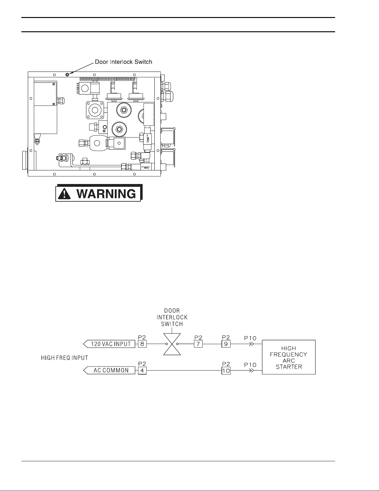
6.3.5 Interlock Switch
The Door Interlock Switch is mounted to the top of
the plumbing box, and is positioned to actuate
when the cover is installed. This switch has three
positions: open, closed, and defeated. When the
plumbing box cover is installed, it depresses the
switch plunger, closing the switch. When the
plumbing box cover is removed, the plunger is
released, and the switch returns to the open
position. The plunger may also be manually pulled
out, where it locks in the defeated position. In this
position the switch contacts are closed. The
defeated position should only be used during
service by qualified technicians.
Electrical Shock Can Kill You! The Door
Interlock Switch should only be defeated
by a qualified service technician. High
Voltage, High Frequency .electricity can be
generated when the Door Interlock Switch
is defeated.
The Door Interlock Switch is wired in series with the
High Frequency Arc Starter, as shown below.
When the switch is open, the 120 VAC input to the
arc starter is disconnected. When the switch is
either closed or defeated, the arc starter will
generate high frequency when the 120 VAC input is
supplied.
Page 38 Maintenance
Page 47

Spark Gap
SmartFlow Plasma System
The SmartFlow plumbing box uses a high
frequency arc starter to initiate the plasma arc
within the cutting torch. The arc starter box is
mounted in the upper left hand corner of the
plumbing box, and contains an adjustable spark
gap.
The spark gap forms one component of an L-C
tank circuit. A capacitor discharges across the
spark gap to create a high frequency signal which is
then coupled to the torch nozzle through the pilot
arc cable.
The spark gap setting is a compromise between
reliable firing and high frequency electrical noise.
As the spark gap setting is increased, more energy
is coupled to the torch, which results in more
reliable firing, and creates more high frequency
noise. As the spark gap setting is decreased, less
electrical noise is generated, but a point may be
reached where the torch will not fire reliably. The
spark gap in the SmartFlow plumbing box should
be adjusted to .060 inches.
Adjustment Procedure
Electrical Shock Can Kill You! Always turn
off power to the plasma power supplies
before opening or servicing the plasma
plumbing box.
1. Remove the cover from the plumbing box.
2. Remove the cover from the arc starter box.
3. Use a feeler gauge to measure the spark gap
setting.
4. If adjustment is required, loosen the locknut on
one of the spark gap electrodes.
5. Turn the hex head on the electrode as
necessary to increase or decrease the spark
gap, then lock in place with the lock nut.
Maintenance Page 39
Page 48

Section 6
6.3.6 Cut Water Pressure
The cut water system uses a carbonator pump with
bypass type pressure regulation to supply high
pressure water to the plumbing box. This pump
requires at least 25 PSI input to prevent cavitating,
and should be adjusted to deliver 120 PSI output.
Output pressure is adjusted by turning the pressure
adjusting screw on the pump body, which is
located beneath an acorn nut.
Adjustment Procedure
1. Remove the acorn nut with an adjustable
wrench.
2. Turn ON the Plasma Test Mode. The cut water
pump will energize, and the cut water solenoid
will open, allowing cut water to preflow through
the torch.
3. Using a screwdriver, turn the pressure adjusting
screw until the pressure gauge reads 120 PSI.
4. Reinstall the acorn nut, then recheck the
pressure setting.
5. Turn OFF the Plasma Test Mode.
Page 40 Maintenance
Page 49

6.3.7 Gas Filters
SmartFlow Plasma System
The nitrogen and oxygen gas supplies must be
filtered before entering the plumbing box. When
using a PT-19XL with secondary shield, the air
supply must also be filtered. Check these filters
regularly and replace the filter element when
necessary. Unfiltered gas supplied to the plumbing
box will result in clogging of the proportional valves
or other plumbing box components.
The gas filters should be installed in the gas supply
lines prior to the Gas Regulator Panel, as shown
below. Use a 5 micron filter.
6.3.8 Gas Proportional Valve
The gas proportional valve controls the flow of gas
to the plasma torch. The same valve is used to
regulate both start gas and cut gas. The Vision
CNC outputs an analog DC voltage signal between
0 and 10 volts representing the desired gas flow
rate. The proportional valve is fully open for a signal
of 10 volts, fully closed at 0 volts.
The gas proportional valve contains no user
servicable parts. In case of failure, the valve should
be replaced or returned to ESAB for repair.
Maintenance Page 41
Page 50

Section 6
6.3.9 Water Proportional Valve
6.3.10 Cooling Water Flow Switch
When the SmartFlow plumbing box is used with a
PT-15XL torch, the water proportional valve
controls the flow of cut water. When the
SmartFlow plumbing box is used in conjunction
with a PT-19XL torch, the water proportional valve
may be used ton control shield air. The Vision CNC
outputs an analog DC voltage signal between 0 and
10 volts representing the desired water flow rate.
The proportional valve is fully open for a signal of 10
volts, fully closed at 0 volts.
The water proportional valve contains no user
servicable parts. In case of failure, the valve should
be replaced or returned to ESAB for repair.
The cooling water circuit uses a 1.0 gallon per
minute flow switch to monitor cooling water flow.
This flow switch is located in the cooling water
return line, so that it indicates actual flow through
the torch. The flow switch is wired as an input to
the numerical, which looks for a change of state of
the input signal when the plasma station is turned
on. Therefore the switch input cannot be jumpered
out of the circuit.
Cooling water flow problems may fall into one of the
following categories:
1. Insufficient flow due to a restriction in the
cooling water circuit.
If a cooling water flow restriction is traced to the
flow switch, the switch may be disassembled
and cleaned, or it may be replaced.
2. Sufficient flow but no flow switch closure.
If measurement of the actual cooling water flow
rate indicates more than 1.0 gallons per minute,
but the flow switch does not close, then the
switch may be damaged or clogged. If
disassembly and cleaning does not remedy the
situation, then the switch must be replaced.
Page 42 Maintenance
Page 51

6.4 Schematics
SmartFlow Plasma System
The schematic below shows the electrical
connections internal to the flow control box. The
schematics are based on the three plug in
connectors, located in the top of the box. All of the
electrical components are wired to those
connectors, where they connect to interface cables
from the CNC.
Maintenance Page 43
Page 52

Section 6
P1 Wiring
Page 44 Maintenance
Page 53

SmartFlow Plasma System
P2 Wiring
Maintenance Page 45
Page 54

Section 6
P3 Wiring
Page 46 Maintenance
Page 55

6.5 Troubleshooting
SmartFlow Plasma System
The following error messages are associated with
the SmartFlow Plasma System, and will appear on
screen at the Vision CNC.
PLASMA STATION n CUT WATER PRESSURE
PLASMA STATION n CUT GAS PRESSURE
This error is generated if the Cut Water Pressure
switch input is in the wrong state. When controlling
a PT-19XL torch’s secondary shield, the Cut Water
Pressure switch monitors shield air pressure.
The CNC watches this input for a change of state,
from the off condition to the on condition when the
cut water solenoid valve is energized. An error is
generated if the input is on when it should be off, or
if the input is off when it should be on.
If this error message appears, check the following:
1. Check the cut water pump, it should be
adjusted to deliver 120 PSI when pumping.
2. Check the appropriate BITI at the Vision CNC.
It should turn on and off with the cut water.
This error is generated if the Cut Gas Pressure
switch input is in the wrong state. This pressure
switch is actuated by start gas during the start ga s
sequence, then by cut gas during cutting.
The CNC watches this input for a change of state,
from the off condition to the on condition when one
of the gas solenoid valves is energized. An error is
generated if the input is on when it should be off, or
if the input is off when it should be on.
If this error message appears, check the following:
1. Check the Nitrogen and Oxygen supply
pressures at the regulator panel. They should
be adjusted to deliver 120 PSI to the plumbing
box.
2. Check the appropriate EPEP at the Vision CNC.
It should turn on and off with the gas flow.
Maintenance Page 47
Page 56

Section 6
PLASMA STATION n COOLING WATER FLOW
PLASMA STATION n DID NOT FIRE
This error is generated when the Cooling Water
Flow Switch input is in the wrong state. The
Cooling Water Flow Switch is in the return line of
the cooling water circuit, and is calibrated to close
at or above 1.0 gallons per minute of flow.
The CNC watches this input for a change of state
from the off condition to the on condition when the
plasma station is turned on. An error is generated if
the input is on when it should be off, or if the input
is off when it should be on.
If this error message appears, check the following:
1. Make sure the Water Cooler is turned on.
2. Check the cooling water recirculator pump. It
should be adjusted to deliver 150 PSI.
3. Check the plasma consumables.
This error is generated all inputs from the plumbing
box are correct, but the torch still does not fire.
The CNC monitors the Arc On input from the
plasma power supply to determine if the arc has
transferred. If the CNC completes a firing
sequence, including energizing the high freq. arc
starter, but does not receive an Arc On input, then
this message is generated.
If this error message appears, check the following:
1. Check the torch consumables for wear or
damage.
2. Open the spark gap cover on the High Freq.
Arc Starter and observe the spark gap while
firing the torch. Verify that a spark is being
generated in the spark gap. Make sure that the
interlock switch in the plumbing box is pulled
out, in the bypass position.
Page 48 Maintenance
Page 57

7 Replacement Parts
7.1 General Information
SmartFlow Plasma System
This section provides replacement parts information
and will assist the service/repair person when
performing maintenance on the system.
The four column parts list for each figure is
arranged to show the assembly relationship of parts
and subassemblies. Information given in each of
these columns is as follows:
Column 1, ITEM: Lists each index number found
on the illustration. When no index number is given
for a part or assembly, it is not illustrated separately
in the illustration, but its name and description
provide identification.
Column 2, PART #: Gives the ESAB part number
of the part or assembly to which the index number
has been assigned. Common hardware items or
other parts readily available for commercial sources
have not been included. Parts purchased by ESAB
from vendors are listed by ESAB part numbers.
Hardware is specified as items in our parts lists but
it normally carries no ESAB part number.
Column 3, QUANTITY: Indicates the quantity of
that part used in that assembly. This quantity
number is not to be used as a recommended
quantity of spare parts. The customer must
determined how many parts are to be purchased
as spare parts.
Column 4, DESCRIPTION: Gives the nam e of the
part or assembly, as well as other information which
will be helpful in identifying it.
Replacement Parts Page 49
Page 58

Section 7
7.2 Ordering Information
When ordering replacement parts, order by part
number and complete description of the part as
given in the description column of the list. In
addition, give the model number of the machine
and the machine serial number. Address all
inquiries to your local ESAB Distributor or to ESAB
Cutting Systems, P.O. Box 100545, Florence,
South Carolina, 29501.
This manual may contain illustrations of parts not
applicable to your specific system. Be sure to
positively identify the correct assembly before
ordering replacement parts to avoid unnecessary
delays.
Page 50 Replacement Parts
Page 59

7.3 SmartFlow Plasma Flow Control
SmartFlow Plasma System
Replacement Parts Page 51
Page 60

Section 7
Valve and Pressure Switch Assembly
Connector Assembly
Page 52 Replacement Parts
Page 61
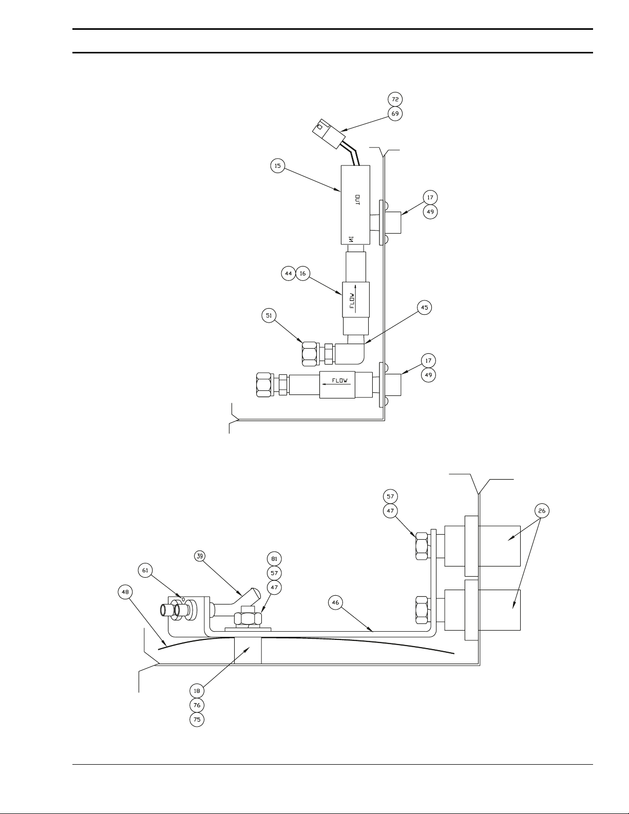
Cooling Water Connections
SmartFlow Plasma System
Buss Bar Connections
Replacement Parts Page 53
Page 62

Section 7
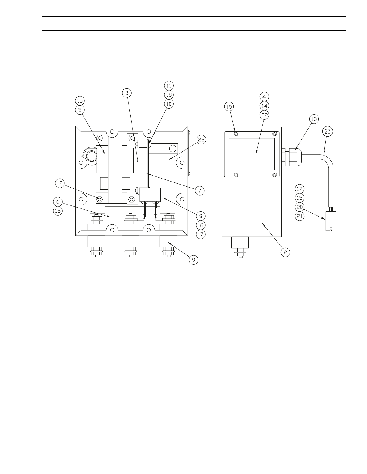
Front Panel Assembly
Item Part # Qty Description
1 Flow Control Assembly
2 56997191 1 Enclosure
3 56997190 1 Cover
4 56998131 1 Pressure Gauge, 0-100 PSI, 2” Dia
5 56998130 1 Regulator, 0-160 PSI, 1/8 NPT
6 33053 1 Torch Connector
7 56998134 3 Solenoid Valve
8 11NZ04 1 Fitting, 1/4 x 1/4 NPTM
9 56997206 1 Exhaust Muffler, 1/8 NPT
10 2078865 1 Door Interlock Switch
11 56997189 1 Manifold Block
12 951982 2 Pressure Switch, 150 PSI
13 56997044 1 Proportional Valve, Cut Water/Shield gas
14 56995748 1 Proportional Valve, Gas
Page 54 Replacement Parts
Page 63

SmartFlow Plasma System
15 636383 1 Cooling Water Flow Switch
16 21124 2 Check Valve
17 58V75 2 Bulkhead Fitting
18 674156 1 Bussbar Standoff
19 98W18 1 O-ring
20 44151300 1 Coupling, 1/8 NPT
21 2062311 2 Safety Cap
22 2 Screw, 6-32x3/16, button hd
23 2234268 1 DIN Rail
24 2234266 3 Connector Socket, 10 Position
25 2234267 3 Connector Plug, 10 Position
26 2062309 2 Male CamLok Receptacle
27 8 Screw, M5-.8x20 Button hd
28 12 Hex Nut, M5-.8 self lock
29 12 Screw, M4-.7x10mm button hd
30 56997186 1 Gas Manifold
31 2 Screw, M6-1x30mm socket hd
32 4 Screw, M6-1x16mm button hd
33 56997187 1 Service Entrance Plate
34 2 Strain Relief
35 2 Strain Relief
36 56997185 1 Blanking Cover
37 2234503 A/R Gasket, EPDM PSA, 3/4 x .90
38 20 Screw, M5-.8x10mm button hd
39 34116 2 Cooling Water Hose Assembly
40 2 Close Nipple, 1/8 NPT Brass
41 2 Elbow, 1/8 NPTM x 1/8 Tube
42 2 Hex Plug, 1/8 NPT
44 1 Nipple, 1/4 NPT x 1-1/2 Brass
45 1 Street Elbow, 1/4 NPTM x 1/4 NPTF Brass
46 56997188 1 Bussbar Assembly
47 3 Hex Nut, 1/2-13
48 33039 1 Nomex Insulator
49 2 Screw, M4-.7 x8mm button hd
50 2 Hex Nut, M4-.7, self locking
51 10Z30 3 Cooling Water Fitting
52 1 Brass Fitting, 1/4 NPTM x 3/8 Tube
53 1 Brass Fitting, 1/8 NPTM x 3/8 Tube, 90
54 1 Fitting, 1/8 NPTM x 1/8 Tube, prestolock
55 A/R Nylon Tubing, 1/8 O.D., Natural
Replacement Parts Page 55
Page 64

Section 7
56 01457226 A/R Copper Tubing, 3/8 O.D. x .308 I.D.
57 3 Split Washer, 1/2
58 84600513 A/R Nomex Sheet, 8.75W x 6.5L x 10 mil
59 1 Set Screw, 1/4-20 hex socket hd
60 2 End Bracket
61 1 Screw, 8-32x3/8 pan hd phillips
62 12 Washer, M4, internal tooth
63 56997180 1 Arc Starter Assembly
64 74S76 2 Start Gas Inlet Fitting
65 3389 1 Oxygen Inlet Fitting
66 11N16 1 Cut Water Inlet Fitting
67 2210514 3 R-C Network (Snubber)
68 4 Ring Terminal, #8 Stud 16AWG
69 4 Connector, 2 Position Plug
70 5 Connector, 2 Position Receptacle
71 10 Terminal Crimp Female, .093
72 8 Terminal Crimp Male, .093
73 2 Terminal Full Ins. Female, .25 18AWG
74 2 Terminal Full Ins. Female, .25 16AWG
75 2 Screw, 6-32 x 5/8 Pan Hd Phillips
76 2 Flat Washer
77 2 Crimp On Terminal /187 Female
79 A/R Wire, #18AWG, 600V, 105 Deg C
80 71200732 A/R DOW 732 RTV Clear Silicon
81 1 Flat Washer, 1/2
82 1 Adaptor Nipple, 1/4 NPT x 1/8 NPT
83 1 Fitting, 1/8 NPTF x 1/8 Tube Prestolok
84 38039 1 Voltage Divider Circuit Board
85 951570 4 Nylon Standoff, 6-32
86 2134208 4 Nylon Hex Nut, 6-32
87 75480012 1 Pressure Plug, 1/16 NPTM Brass
Page 56 Replacement Parts
Page 65
7.3.1 Arc Starter Box Assembly
Assembly 56997180
SmartFlow Plasma System
Replacement Parts Page 57
Page 66

Section 7
Item Part # Qty Description
1 56997180 High Frequency Arc Starter Assembly
2 56997179 1 Enclosure
3 56997178 1 PC Board Mounting Bracket
4 56997177 1 Access Cover
5 951179 1 Transformer
6 56997157 1 Choke
7 31490 1 High Frequency Circuit Board
8 2239157 1 Capacitor
9 3 High Voltage Feed Through
10 4 Unthreaded Spacer
11 4 Screw, 6-32x.75 pan hd
12 4 Hex Nut/Star Washer, 8-32
13 1 Strain Relief
14 A/R EDPM Gasket, 3/4 x .090
15 10 Full Insulated Terminal, .25 Female
16 2 Terminal, 1/4 ring, #18-14 AWG
17 A/R Wire, #18AWG 600V, black, 105º C.
18 5 Hex Nut/Star Washer, 6-32
19 4 Screw, M4-.7x8mm Button Hd
20 1 Connector Receptacle, 2 Position
21 2 Terminal Crimp .093 Fem #14-20AWG
22 1 Nomex Insulator, .10 Thick
23 90862534 A/R Fiberglass Tubing, .204 ID
Page 58 Replacement Parts
Page 67

7.3.2 Flow Tube Box Assembly
SmartFlow Plasma System
Replacement Parts Page 59
Page 68

Section 7
Item Part # Qty Description
1 56997181 1 Enclosure
2 56997182 1 Cover
3 12 Fitting, 1/4 NPTM x 3/8 Tube Gyrolock
4 58V58 2 Nitrogen Gas Bulkhead Fitting
5 679064 2 Oxygen Gas Bulkhead Fitting
6 58V75 2 Cut Water Bulkhead Fitting
7 821124 3 Check Valve
8 01457226 A/R Copper Tubing, .38 OD x .308 ID
9 21898 3 Flowmeter Body
10 996854 1 Cut Water Float Ball
11 3 Brass Fitting, 1/4 NPTM
12 A/R Teflon Tape
13 30 Screw, M4-.7x8mm Button Hd
14 6 Hex Nut, M4-.7, Nylon Self Lock
15 2132818 4 Hole Plug, .312, Nylon, Black
Page 60 Replacement Parts
Page 69

SmartFlow Plasma System
Replacement Parts Page 61
Page 70

F 14 - 129 8/97 Printed in USA
 Loading...