


RT Robo Welding Torch System
RTKS-2, RTFL-2, KSC-2, FLC-2, RT42, RT52,
RT62, RT72, RT82, RT42-NG, RT82WNG
Instrukcja obsługi
0463 373 101 PL 20181227


SPIS TREŚCI
1
BEZPIECZEŃSTWO.................................................................................... 5
1.1 Znaczenie symboli ................................................................................. 5
1.2 Zalecenia dotyczące bezpieczeństwa .................................................. 5
2
GWARANCJA.............................................................................................. 9
2.1 Warunki przeznaczenia .......................................................................... 9
3
WPROWADZENIE ....................................................................................... 11
3.1 Przegląd systemu uchwytów spawalniczych ...................................... 12
4
DANE TECHNICZNE ................................................................................... 14
4.1 Szyjka uchwytu spawalniczego ............................................................ 14
4.2 Klasa napięcia ........................................................................................ 16
4.2.1 Wartości graniczne obwodu chłodzenia ............................................... 16
4.3 Uchwyt montażowy ................................................................................ 17
4.3.1 Mocowania uchwytu do systemu standardowego RT .......................... 17
4.3.1.1 Mechanizm bezpieczeństwa RTKS-2............................................... 18
4.3.1.2 Kołnierz pośredni RTFL-2................................................................. 18
4.3.2 Uchwyty montażowe do systemu z przegubem przelotowym .............. 19
4.3.2.1 Uchwyt montażowy RTKSC-2 G/W z mechanizmem
bezpieczeństwa.................................................................................
4.3.2.2 Uchwyt montażowy RTFLC-2 G/W................................................... 21
4.4 Kołnierze adaptera ................................................................................. 22
4.5 Zespoły kabla.......................................................................................... 22
4.5.1 Złącza kabla do standardowego systemu RT....................................... 23
4.5.2 Zespoły kabla do systemów z przegubem przelotowym ...................... 23
5
INSTALLATION............................................................................................ 25
5.1 RTKS-2 standard arm installation........................................................ 25
5.1.1 RTKS-2 safety-off mechanism............................................................. 25
5.1.1.1 Torch installation with adjustable mount............................................ 26
5.1.2 Standard arm cable assembly for KS-2 and FL-2 ................................ 28
5.1.3 RTKS-2 wire feeder connection........................................................... 29
5.1.4 RTKS-2 electrical connections ............................................................ 30
5.1.4.1 RTKS-2 safety-off mechanism connection ....................................... 30
5.1.5 RTKS-2 Torch installation .................................................................... 31
5.2 RTFL-2 standard arm installation ........................................................ 32
20
5.2.1 RTFL-2 rigid mount.............................................................................. 32
5.2.2 RTFL-2 torch installation ..................................................................... 34
5.3 RTKSC-2 hollow wrist system installation.......................................... 34
5.3.1 RTKSC-2 mount with safety off mechanism........................................ 34
5.3.2 Mounting the cable assembly............................................................... 35
5.3.2.1 RTKSC-2 feeder cabinet connections .............................................. 36
5.3.3 RTKSC-2 cable assembly ................................................................... 38
5.3.3.1 RTKSC-2 cable assembly installation .............................................. 38
0463 373 101 © ESAB AB 2018

SPIS TREŚCI
5.3.3.2 RTKSC-2 electrical connections....................................................... 41
5.3.4 RTKSC-2 torch installation .................................................................. 42
5.4 RTFLC-2 installation.............................................................................. 43
5.4.1 RTFLC-2 mount................................................................................... 43
5.4.2 RTFLC-2 wire feeder connection......................................................... 43
5.4.2.1 Feeding through the robot arm.......................................................... 43
5.4.2.2 RTFLC-2 feeder cabinet connections............................................... 44
5.4.3 RTFLC-2 cable assembly .................................................................... 46
5.4.3.1 RTFLC-2 cable assembly installation ............................................... 46
5.4.4 RTFLC-2 electrical connections .......................................................... 49
5.4.4.1 RTFLC-2 hollow wrist system with Infiniturn cable assembly ........... 49
5.4.4.2 RTFLC-2 hollow wrist system with Helix cable assembly................. 50
5.5 Torch installation.................................................................................... 50
5.5.1 Torch neck equipment .......................................................................... 50
5.5.2 Aristo RT torch neck installation........................................................... 51
5.6 Installing the wire guide for standard and hollow Wrist arm ............. 52
5.6.1 Installing the neck liner......................................................................... 52
5.6.2 Installing a split wire guide in the cable assembly ................................ 53
5.6.3 Installing a continuous wire guide in the cable assembly ..................... 55
5.7 Adjust the narrow gap contact tip ........................................................ 56
6
OPERATION ................................................................................................ 59
6.1 Important information for programming (hollow wrist system only) 59
7
OBSŁUGA I KONSERWACJA .................................................................... 61
7.1 Obowiązkowe kontrole i działania ........................................................ 61
8
ROZWIĄZYWANIE PROBLEMÓW ............................................................. 63
9
ZAMAWIANIE CZĘŚCI ZAMIENNYCH ....................................................... 65
Dane techniczne mogą ulec zmianie bez uprzedzenia.
0463 373 101 © ESAB AB 2018

1 BEZPIECZEŃSTWO
1 BEZPIECZEŃSTWO
1.1 Znaczenie symboli
Użyte w dalszej części niniejszej instrukcji oznaczają: Uwaga! Należy mieć się na
baczności!
NIEBEZPIECZEŃSTWO!
Oznacza bezpośrednie zagrożenia, które, jeśli nie uda się ich uniknąć, będą
skutkować odniesieniem bezpośrednich, poważnych obrażeń ciała lub
śmiercią.
OSTRZEŻENIE!
Oznacza potencjalne zagrożenia, które mogą skutkować odniesieniem
obrażeń ciała lub śmiercią.
PRZESTROGA!
Oznacza zagrożenia, które mogą skutkować odniesieniem niewielkich
obrażeń ciała.
OSTRZEŻENIE!
Przed użyciem należy przeczytać ze zrozumieniem
instrukcję obsługi, wszystkie oznaczenia, przepisy BHP
oraz karty charakterystyki (SDS).
1.2 Zalecenia dotyczące bezpieczeństwa
Użytkownicy urządzeń firmy ESAB ponoszą odpowiedzialność za stosowanie odpowiednich
środków ostrożności przez osoby używające lub znajdujące się w pobliżu tych urządzeń.
Środki ostrożności muszą spełniać wymagania stawiane tego rodzaju urządzeniom
spawalniczym. Poza standardowymi przepisami dotyczącymi miejsca pracy należy
przestrzegać następujących zaleceń.
Wszelkie prace powinny być wykonywane przez przeszkolony personel, dobrze znający
zasady działania urządzenia. Nieprawidłowa obsługa urządzenia może prowadzić do sytuacji
niebezpiecznych, a w rezultacie do obrażeń operatora oraz uszkodzenia sprzętu.
1. Każdy, kto używa urządzenia, powinien znać:
○ zasady jego obsługi
○ lokalizację wyłączników awaryjnych
○ jego działanie
○ odpowiednie środki ostrożności
○ zasady spawania i cięcia lub innego typu eksploatacji urządzenia
2. Operator powinien dopilnować, aby:
○ w momencie uruchamiania urządzenia w jego pobliżu nie było żadnych osób
nieupoważnionych
○ w chwili zajarzania łuku lub rozpoczęcia prac przy użyciu urządzenia wszystkie
osoby były odpowiednio zabezpieczone
3. Miejsce pracy powinno być:
○ odpowiednie do określonego celu
○ wolne od przeciągów
0463 373 101
- 5 -
© ESAB AB 2018

1 BEZPIECZEŃSTWO
4. Sprzęt ochrony osobistej:
○ Należy zawsze stosować zalecany sprzęt ochrony osobistej, taki jak okulary
ochronne, odzież ognioodporna, rękawice ochronne
○ Nie należy nosić żadnych luźnych elementów odzieży, takich jak szaliki,
bransolety, pierścionki itp., które mogłyby o coś zahaczyć lub spowodować
poparzenie
5. Ogólne środki ostrożności:
○ Upewnić się, że przewód masowy jest podłączony prawidłowo
○ Prace na urządzeniach wysokiego napięcia mogą być wykonywane wyłącznie
przez wykwalifikowanego elektryka
○ Odpowiedni sprzęt gaśniczy musi być wyraźnie oznaczony i znajdować się w
pobliżu.
○ W trakcie pracy urządzenia nie wolno przeprowadzać jego smarowania ani
konserwacji
OSTRZEŻENIE!
Spawanie i cięcie łukowe może stwarzać zagrożenie dla operatora i innych osób.
Podczas spawania lub cięcia należy stosować odpowiednie środki ostrożności.
PORAŻENIE PRĄDEM ELEKTRYCZNYM — może skutkować śmiercią
• Przeprowadzić montaż i uziemienie urządzenia spawalniczego zgodnie z
instrukcją obsługi.
• Nie dotykać elementów pod napięciem ani elektrod odsłoniętą skórą, w
mokrych rękawicach lub w mokrej odzieży.
• Odizolować się od obrabianego przedmiotu i ziemi.
• Upewnić się, że stanowisko pracy jest bezpieczne
POLA ELEKTRYCZNE I MAGNETYCZNE — mogą być szkodliwe dla
zdrowia
• Spawacze z wszczepionymi rozrusznikami serca powinni przed
rozpoczęciem spawania zasięgnąć opinii lekarza. Pole
elektromagnetyczne może zakłócać pracę niektórych rozruszników.
• Narażenie na działanie pola elektromagnetycznego może też mieć inne
skutki zdrowotne, które są nieznane.
• Spawacze powinni stosować się do następujących procedur, aby
ograniczyć skutki narażenia na działanie pola elektromagnetycznego:
○ Poprowadzić elektrodę i przewody robocze po tej samej stronie ciała.
Jeśli to możliwe, zabezpieczyć je taśmą klejącą. Nie stawać miedzy
uchwytem przewodem spawalniczym a roboczym. W żadnym
wypadku nie owijać przewodu spawalniczego ani roboczego wokół
ciała. Ustawić źródło zasilania i przewody jak najdalej od ciała.
○ Przewód roboczy podłączać do przedmiotu obrabianego możliwie
najbliżej obszaru spawania.
0463 373 101
GAZY I OPARY — mogą być szkodliwe dla zdrowia
• Trzymaj głowę z dala od oparów.
• Stosować wentylację, odprowadzanie przy łuku lub obydwa
zabezpieczenia, usuwając opary i gazy ze strefy oddychania i miejsca
pracy.
- 6 -
© ESAB AB 2018

1 BEZPIECZEŃSTWO
PROMIENIOWANIE ŁUKU – Może powodować obrażenia oczu i poparzenia
skóry
• Chronić oczy i ciało. Stosować odpowiednią maskę spawalniczą i szkła
filtrujące oraz nosić odzież ochronną.
• Chroń osoby znajdujące się w pobliżu, stosując odpowiednie ekrany lub
zasłony.
HAŁAS — nadmierny hałas może uszkodzić słuch
Chronić uszy. Stosować słuchawki wyciszające lub inne zabezpieczenie.
CZĘŚCI RUCHOME — mogą powodować obrażenia ciała
• Wszystkie drzwi, panele i pokrywy powinny być zamknięte i bezpiecznie
zamocowane. Tylko wykwalifikowani pracownicy powinni zdejmować
osłony w przypadku konieczności wykonania konserwacji i usunięcia
usterek. Po zakończeniu serwisowania i przed uruchomieniem silnika
należy zamontować panele lub pokrywy i zamknąć drzwi.
• Zatrzymać silnik przed montażem lub podłączeniem urządzenia.
• Nigdy nie zbliżać rąk, włosów, luźnej odzieży ani narzędzi do ruchomych
części.
ZAGROŻENIE POŻAREM
• Iskry (rozpryski) mogą spowodować pożar. Upewnić się, że w pobliżu nie
ma materiałów łatwopalnych.
• Nie używać na zamkniętych pojemnikach.
WADLIWE DZIAŁANIE — w razie nieprawidłowego działania poprosić o pomoc
fachowca.
CHROŃ SIEBIE I INNYCH!
PRZESTROGA!
Niniejszy produkt jest przeznaczony wyłącznie do spawania łukowego.
OSTRZEŻENIE!
Nie używaj źródła prądu do rozmrażania zamarzniętych rur.
PRZESTROGA!
Urządzenia klasy A nie są przeznaczone do użytku w
budynkach, gdzie zasilanie elektryczne pochodzi z
publicznego niskonapięciowego układu zasilania. Ze
względu na przewodzone i emitowane zakłócenia, w
takich lokalizacjach mogą występować potencjalne
trudności w zapewnieniu kompatybilności
elektromagnetycznej urządzeń klasy A.
0463 373 101
- 7 -
© ESAB AB 2018

1 BEZPIECZEŃSTWO
UWAGA!
Zużyty sprzęt elektroniczny należy przekazać do
zakładu utylizacji odpadów!
Zgodnie z dyrektywą europejską 2012/19/WE w sprawie
zużytego sprzętu elektrycznego i elektronicznego
(WEEE) oraz jej zastosowaniem w świetle prawa
krajowego, wyeksploatowane urządzenia elektryczne
i/lub elektroniczne należy przekazywać do zakładu
utylizacji odpadów.
Jako osoba odpowiedzialna za sprzęt, operator ma
obowiązek uzyskać informacje o odpowiednich
punktach zbiórki odpadów.
Dodatkowych informacji udzieli lokalny dealer firmy
ESAB.
ESAB oferuje asortyment akcesoriów spawalniczych i sprzęt ochrony osobistej. Aby
uzyskać informacje na temat składania zamówień, należy skontaktować się z lokalnym
dealerem ESAB lub odwiedzić naszą stronę internetową.
0463 373 101
- 8 -
© ESAB AB 2018

2 GWARANCJA
2 GWARANCJA
Przed dostawą nasze produkty są dokładnie sprawdzane. Firma ESAB gwarantuje, że
wszystkie produkty są wolne od wad materiału i wykonawstwa w momencie dostawy oraz że
działają zgodnie z przeznaczeniem.
Firma ESAB zapewnia gwarancję w zakresie wad materiału i wykonawstwa zgodnie z
wymaganiami prawnymi. Gwarancją tą nie są objęte materiały eksploatacyjne.
Gwarancja nie obejmuje uszkodzeń i defektów funkcjonalnych spowodowanych:
• przeładowaniem, nadużyciami i nieprawidłowym wykorzystaniem produktu
• kolizjami i wypadkami
• brakiem zachowania zgodności z instrukcjami wymienionymi w tym podręczniku
• nieprawidłową instalacją lub montażem
• niewystarczającą konserwacją
• modyfikacją produktu i zmianą jego stanu początkowego
• działaniem substancji chemicznych
• zwykłym zużyciem
Firma ESAB nie przyjmuje żadnej odpowiedzialności poza wymianą lub naprawą
uszkodzonych części.
2.1 Warunki przeznaczenia
1. Produkt jest przeznaczony do użytku przemysłowego i komercyjnego. Powinien być
używany wyłącznie przez przeszkolony personel. Producent nie jest odpowiedzialny
za żadne szkody i wypadki wynikające z nieprawidłowego użytkowania.
2. System spawania zrobotyzowanego Aristo® RT został zaprojektowany i
wyprodukowany zgodnie z najnowszymi technologiami. Jest bezpieczny i niezawodny,
jeśli wszystkie czynności z zakresu obsługi, montażu i konserwacji wykonuje
odpowiednio przeszkolony personel. Należy przestrzegać instrukcji montażu, obsługi i
konserwacji opisanych w niniejszym dokumencie.
3. System spawania zrobotyzowanego Aristo® RT może być instalowany, obsługiwany i
serwisowany jedynie przez wyszkolony personel. Należy przestrzegać instrukcji
instalacji, obsługi i konserwacji opisanych w niniejszym podręczniku.
4. System spawania zrobotyzowanego Aristo® RT może być używany wyłącznie do
celów, do których jest przeznaczony, zgodnie z jego danymi technicznymi oraz przy
użyciu zautomatyzowanych systemów obsługi. Należy wybrać typ uchwytu zgodny z
danym zadaniem spawania.
5. System spawania zrobotyzowanego Aristo® RT został zaprojektowany do użytku jako
kompletny system. Nie dopuszcza się uzupełniania systemu o komponenty innych
producentów.
6. Układy RTKS-2 i RTKSC-2 mogą być używane wyłącznie jako mechanizmy
wyłączenia awaryjnego zgodnie z ich specyfikacjami technicznymi i w połączeniu ze
standardowym zespołem kabla ramienia RT (KS-2), Infiniturn lub Helix (KSC-2),
kołnierzem adaptera ESAB, wraz z uchwytami montażowymi RT (KS-2) i uchwytem
spawalniczym Aristo RT.
7. Do gazu wydmuchowego nie należy dodawać oleju ani płynu przeciwrozpryskowego.
Firma ESAB nie gwarantuje odporności chemicznej na te substancje. Firma ESAB
zaleca stosowanie urządzenia zraszającego ESAB do nakładania na uchwyt
minimalnej ilości płynu przeciwrozpryskowego, a tym samym ochrony środowiska.
0463 373 101
- 9 -
© ESAB AB 2018

2 GWARANCJA
8. Produkt należy przechowywać w warunkach suchych. Musi być chroniony przed
wilgocią podczas transportu, przechowywania i użytkowania.
9. System został zaprojektowany do użytku przy temperaturze otoczenia w zakresie od
5°C do 40°C (41°F do 104°F). W przypadku przekroczenia tych limitów wymagane
jest podjęcie konkretnych działań. W przypadku ryzyka zamrożenia należy
zastosować odpowiednie chłodziwo.
0463 373 101
- 10 -
© ESAB AB 2018

3 WPROWADZENIE
3 WPROWADZENIE
Systemy uchwytów spawalniczych RT zostały stworzone do stosowania w pełni
automatycznym spawaniu MIG/MAG z użyciem robotów spawalniczych. Systemy składają
się z wielu rodzajów szyjek uchwytów Aristo RT przeznaczonych do pracy zrobotyzowanej,
uchwytów montażowych, zespołów kabli zoptymalizowanych pod kątem pracy
zrobotyzowanej oraz zabezpieczających funkcji bezpieczeństwa, których celem jest
zapobieganie uszkodzeniu systemu w przypadku kolizji.
Standardowy system spawania RT zapewnia ochronę przed kolizjami dzięki zastosowaniu
układu RTKS-2, który jest mechaniczną funkcją bezpieczeństwa działającą w oparciu o
mechanizm sprężynowy. Można go opcjonalnie zastąpić modelem RTFL-2, aby wykorzystać
funkcję wykrywania kolizji systemu sterowania robota. Standardowy system spawalniczy RT
może być używany z różnymi typami zespołów kabli.
Uchwyty montażowe RTKSC-2 i RTFLC-2 z zespołami kabli Infiniturn lub Helix są
przeznaczone do użytku w zrobotyzowanych systemach spawalniczych z przegubem
przelotowym przeznaczonych do zaawansowanych prac spawalniczych. Mechanizm
bezpieczeństwa w uchwycie montażowym RTKSC-2 pozwala na znaczne elastyczne
wygięcie uchwytu w przypadku kolizji. Zespoły kabli Infiniturn i Helix są proste w montażu, co
zapewnia wysoką niezawodność i precyzję manewrowania.
W połączeniu ze sprawdzonymi zrobotyzowanymi uchwytami spawalniczymi Aristo RT
urządzenia te tworzą wysoce niezawodny i trwały system, który wymaga jedynie minimalnej
konserwacji.
Instrukcja obsługi znajduje się w zestawie uchwytów montażowych i zespołów kabli.
Numery zamówieniowe ESAB, dostępne akcesoria, części zamienne i części
eksploatacyjne można znaleźć na liście części zamiennych.
0463 373 101
- 11 -
© ESAB AB 2018

3 WPROWADZENIE
3.1 Przegląd systemu uchwytów spawalniczych
Standardowy system RT
Szczegółowy opis znajduje się w
odpowiedniej części rozdziału DANE
TECHNICZNE:
1. Szyjka uchwytu
Patrz „Uchwyt spawalniczy”.
2. Zespół kabla
Patrz „Złącza kabla do
standardowego systemu RT”.
3. Uchwyt montażowy
Patrz „Uchwyty montażowe do
standardowego systemu RT”.
4. Mechanizm bezpieczeństwa
RTKS-2
Patrz „Mechanizm bezpieczeństwa
RTKS-2”.
5. Kołnierz pośredni RTFL-2
Patrz „Kołnierz pośredni RTFL-2”.
6. Kołnierz adaptera (w razie
potrzeby)
Patrz „Kołnierze adapterów”.
0463 373 101
- 12 -
© ESAB AB 2018

3 WPROWADZENIE
System z przegubem przelotowym
Szczegółowy opis znajduje się w
odpowiedniej części rozdziału DANE
TECHNICZNE:
1. Szyjka uchwytu
Patrz „Uchwyt spawalniczy”.
2. Uchwyt montażowy RTKSC-2
Patrz „Uchwyt montażowy
RTKSC-2 z mechanizmem
bezpieczeństwa”.
3. Uchwyt montażowy RTFLC-2
Patrz „Sztywny uchwyt montażowy
RTFLC-2”.
4. Kołnierz adaptera
Patrz „Kołnierze adapterów”.
5. Zespół kabla Helix lub Infiniturn
Patrz „Zespoły kabla do systemów z
przegubem przelotowym”
0463 373 101
- 13 -
© ESAB AB 2018

4 DANE TECHNICZNE
4 DANE TECHNICZNE
4.1 Szyjka uchwytu spawalniczego
Model uchwytu należy wybrać zgodnie z zastosowaniem. Należy wziąć pod uwagę
wymagany cykl pracy i wydajność, metodę chłodzenia i średnicę drutu. W przypadku
podwyższonych wymagań, wynikających na przykład z wstępnego ogrzania elementów
obrabianych lub odbijania ciepła w narożach, czynniki te muszą zostać wzięte pod uwagę i
należy wybrać uchwyt spawalniczy o odpowiedniej rezerwie mocy.
Uchwyty spawalnicze RT są przeznaczone do użytku ze zgodnymi z normą CE źródłami
prądu spawania do procesów spawania metali w gazie obojętnym (MIG), spawania metali w
gazie aktywnym (MAG) i lutospawaniu MIG przy użyciu okrągłych drutów komercyjnych. Nie
należy stosować uchwytu do innych celów.
W przypadku spawania stali lub aluminium łukiem pulsacyjnym należy użyć uchwytu
chłodzonego wodą RT82W.
Patrz dostępne modele uchwytów poniżej.
Model uchwytu
Metoda chłodzenia Gaz osłonowy Wartość
RT42G Z chłodzeniem
gazowym
Z chłodzeniem
gazowym
Z chłodzeniem
gazowym
Z chłodzeniem
gazowym
RT42W Z chłodzeniem
wodnym
Z chłodzeniem
wodnym
Z chłodzeniem
wodnym
Z chłodzeniem
wodnym
RT52G Z chłodzeniem
gazowym
znamionowa
CO
2
420A / 60%
300A / 100%
Mieszany 350A / 60%
250A / 100%
CO
2
420A / 60%
420A / 100%
Mieszany 350A / 60%
350A / 100%
CO
2
420A / 60%
0463 373 101
Z chłodzeniem
gazowym
Z chłodzeniem
gazowym
Z chłodzeniem
gazowym
300A / 100%
Mieszany 350A / 60%
250A / 100%
- 14 -
© ESAB AB 2018

4 DANE TECHNICZNE
Model uchwytu
Metoda chłodzenia Gaz osłonowy Wartość
RT52W Z chłodzeniem
wodnym
Z chłodzeniem
wodnym
Z chłodzeniem
wodnym
Z chłodzeniem
wodnym
RT62G Z chłodzeniem
gazowym
Z chłodzeniem
gazowym
Z chłodzeniem
gazowym
Z chłodzeniem
gazowym
RT62W Z chłodzeniem
wodnym
znamionowa
CO
2
470A / 60%
470A / 100%
Mieszany 400A / 60%
400A / 100%
CO
2
500A / 60%
340A / 100%
Mieszany 420A / 60%
290A / 100%
CO
2
530A / 60%
Z chłodzeniem
wodnym
Z chłodzeniem
wodnym
Z chłodzeniem
wodnym
RT72G Z chłodzeniem
gazowym
Z chłodzeniem
gazowym
Z chłodzeniem
gazowym
Z chłodzeniem
gazowym
RT72W Z chłodzeniem
wodnym
Z chłodzeniem
wodnym
Z chłodzeniem
wodnym
530A / 100%
Mieszany 450A / 60%
450A / 100%
CO
2
480A / 60%
320A / 100%
Mieszany 400A / 60%
270A / 100%
CO
2
480A / 60%
430A / 100%
Mieszany 480A / 60%
0463 373 101
Z chłodzeniem
wodnym
- 15 -
430A / 100%
© ESAB AB 2018

4 DANE TECHNICZNE
Model uchwytu
RT82W Z chłodzeniem
Metoda chłodzenia Gaz osłonowy Wartość
znamionowa
CO
2
600A / 60%
wodnym
Z chłodzeniem
600A / 100%
wodnym
Z chłodzeniem
Mieszany 550A / 60%
wodnym
Z chłodzeniem
550A / 100%
wodnym
Wartości parametrów znamionowych uchwytu i cyklu pracy są podane dla cykli
10-minutowych.
Dane techniczne dotyczą standardowego zastosowania z wykorzystaniem części
eksploatacyjnych/zamiennych. Przy korzystaniu z trybu transferu metalu w łuku impulsowym
moc znamionowa uchwytu jest zmniejszona.
Zakresy temperatur Przechowywanie: -15-50°C (5-122°F)
Eksploatacja: 5–40°C (41–104°F)
Gaz wydmuchowy Maksymalnie 10 bar, oddzielny wąż gazu
Masa całkowita (szyjka uchwytu, mechanizm
Około 5 kg
bezpieczeństwa, uchwyt montażowy i zespół
kabla 1 m)
4.2 Klasa napięcia
Maks. dopuszczalne napięcie/natężenie
prądu
Kompletny system uchwytu spawalniczego 141 V (wartość szczytowa dla spawania)
Obwód sterowania funkcji bezpieczeństwa
RTKS-2
Przycisk RTKS-2
Obwód sterowania funkcji bezpieczeństwa
RTKSC-2
Używanie funkcji wykrywania dyszy ze
standardowym zespołem kabli
Używanie funkcji wykrywania dyszy w
zespołach kabli Helix lub Infiniturn
24 V / 1 A
48 V / 0,1 A
48 V
50 V / 5 A
(Dopuszczalne obciążenie maks. przez 1
minutę przy prądzie znamionowym)
50 V / 5 A
(Dopuszczalne obciążenie maks. przez 1
minutę przy prądzie znamionowym)
Wskazane klasy odnoszą się do standardowych przypadków zastosowania.
Wartości znamionowe zespołów kablowych podano w części „Zespoły kabla”.
4.2.1 Wartości graniczne obwodu chłodzenia
Dotyczy tylko wersji chłodzonej wodą.
0463 373 101
- 16 -
© ESAB AB 2018

4 DANE TECHNICZNE
Min. natężenie przepływu
wody:
1,0 l/min (1,1 kwarty/min)
Min. ciśnienie wody: 2,5 bara (36,3 PSI)
Maks. ciśnienie wody: 3,5 bara (50,8 PSI)
Temperatura wlotu: Maks. 40°C (104°F)
Temperatura powrotu: Maks. 60°C (140°F)
Wydajność chłodzenia: Min. 1000 W, zależnie od zastosowania
PRZESTROGA!
Temperatury powrotu przekraczające 60°C (140°F) mogą spowodować uszkodzenie
lub zniszczenie zespołu kabla.
4.3 Uchwyt montażowy
Wymagany typ uchwytu montażowego zależy od konstrukcji systemu uchwytu
spawalniczego RT oraz od wyboru urządzeń bezpieczeństwa, patrz część „Przegląd
systemów uchwytów spawalniczych”.
Podzespół Przybliżona masa
Uchwyt montażowy (do systemu
standardowego)
0,43 kg
Mechanizm bezpieczeństwa RTKS-2 (do
0,85 kg
systemu standardowego)
Kołnierz pośredni RTFL-2 (do systemu
0,35 kg
standardowego)
Uchwyt montażowy RTKSC-2 (do systemu z
1,90 kg
przegubem przelotowym)
Sztywny uchwyt montażowy RTFLC-2 (do
1,22 kg
systemu z przegubem przelotowym)
Zrobotyzowany uchwyt spawalniczy 0,66 kg
4.3.1 Mocowania uchwytu do systemu standardowego RT
W przypadku standardowych systemów RT uchwyt montażowy jest montowany na
mechanizmie bezpieczeństwa RTKS-2 (lub na kołnierzu pośrednim RTFL-2) i zaciska
zespół kabla oraz podłączoną szyjkę uchwytu.
Uchwyty montażowe należy wybierać zawsze zgodnie z typem uchwytu i jego geometrią.
Możliwe jest zastosowanie różnych typów uchwytów. Informacje na temat dostępnych
uchwytów montażowych do standardowego systemu RT znajdują się na liście części
zamiennych.
0463 373 101
- 17 -
© ESAB AB 2018

4 DANE TECHNICZNE
Uchwyt montażowy do robotów ze standardowym ramieniem
4.3.1.1 Mechanizm bezpieczeństwa RTKS-2
Mechanizm bezpieczeństwa RTKS-2 to urządzenie sprężynowe, które chroni robota i
system uchwytu w przypadku kolizji.
UWAGA!
Nie należy rozmontowywać urządzenia RTKS-2.
4.3.1.2 Kołnierz pośredni RTFL-2
Można stosować sztywny kołnierz pośredni RTFL-2 zamiast RTKS-2, jeśli robot jest
wyposażony w elektroniczny system wykrywania kolizji.
0463 373 101
- 18 -
© ESAB AB 2018

4 DANE TECHNICZNE
4.3.2 Uchwyty montażowe do systemu z przegubem przelotowym
W systemie z przegubem przelotowym szyjki uchwytów spawalniczych Aristo RT są
podłączone do uchwytu montażowego KSC-2 lub FLC-2.
Uchwyt montażowy RTKSC-2 gwarantuje elastyczne wygięcie w przypadku kolizji. W tym
samym czasie następuje otwarcie styku elektrycznego, co stanowi sygnał do zatrzymania
sterowania robotem. Po zresetowaniu błędu początkowa geometria i punkt środkowy
narzędzia (TCP) uchwytu spawalniczego będą osiągane z dużą precyzją. Układ jest
całkowicie mechaniczny i zasilany sprężynowo.
Uchwyt montażowy RTFLC-2 nie ma wbudowanej funkcji bezpieczeństwa.
W przypadku systemów z przegubem przelotowym zaleca się stosowanie RTKSC-2 G/W
(lub RTFLC-2 G/W). Uchwyt montażowy może być używany z uchwytami serii Aristo RT
chłodzonymi zarówno gazem, jak i wodą.
RTKSC-2 G/W RTFLC-2 G/W
Zasada działania
mechanizmu bezpieczeństwa
Mechaniczny Nie dotyczy (mocowanie
sztywne)
Osiowa siła zwalniająca (Fz) 650 N Nie dotyczy (mocowanie
sztywne)
Moment zwolnienia na osi
poprzecznej (Mx)
24 Nm Nie dotyczy (mocowanie
sztywne)
Zresetować po zwolnieniu Automatyczny Nie dotyczy (mocowanie
sztywne)
Powtarzalność Boczna ± 0,1 mm przy TCP
standardowego uchwytu
Nie dotyczy (mocowanie
sztywne)
Aristo RT
Maks. ugięcie Około ± 8° Nie dotyczy (mocowanie
sztywne)
Wyłącznik bezpieczeństwa Normalnie zwarty
Maks. obciążenie elektryczne
Nie dotyczy (mocowanie
sztywne)
48 V / 1 A
0463 373 101
- 19 -
© ESAB AB 2018
4 DANE TECHNICZNE
Elektryczny obwód
sterowania dla funkcji
wykrywania dyszy
Wartość znamionowa:
• Zespoły kabli Helix:
maks. 50 V DC / 5 A,
maks. 1 minuta
Po wykryciu styku
szybko odłączyć
napięcie czujnika.
• W przypadku zespołów
kabli Infiniturn funkcja
wykrywania dyszy działa
w ograniczonym
zakresie. Aby uzyskać
szczegółowe informacje
na temat możliwych
rozwiązań w danym
zastosowaniu, należy
skontaktować się z firmą
ESAB.
Klasa napięcia Maksymalne dopuszczalne
napięcie w obwodzie
sterowania wyłączania
awaryjnego: 48 V.
Wartość znamionowa:
• Zespoły kabli Helix:
maks. 50 V DC / 5 A,
maks. 1 minuta
• Zespoły kabli Infiniturn:
maks. 50 V DC / 1 A,
maks. 1 minuta
Po wykryciu styku szybko
odłączyć napięcie czujnika.
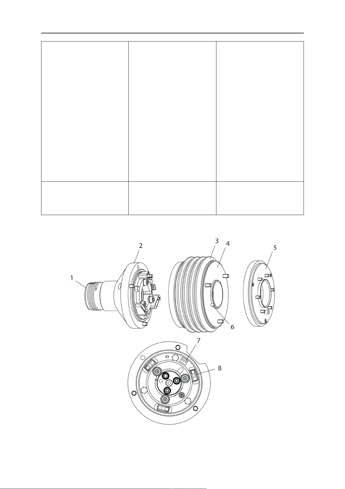
4.3.2.1 Uchwyt montażowy RTKSC-2 G/W z mechanizmem bezpieczeństwa
0463 373 101
- 20 -
© ESAB AB 2018

4 DANE TECHNICZNE
Elem
Opis Działanie
ent
1 Wspornik szyjki uchwytu Interfejs uchwytu Aristo RT
2 Pokrywa RTKSC-2 Zespół z interfejsami kabla i uchwytu
3 Gumowa osłona Zabezpieczenie mechanizmu bezpieczeństwa
4 Główny korpus RTKSC-2 Umożliwia mechaniczne ugięcie w przypadku kolizji
5 Kołnierz adaptera Interfejs izolujący do przegubu robota (musi być
dopasowany do konkretnego robota)
6 Sworzeń indeksowy Do precyzyjnego osiowania na kołnierzu adaptera
7 Złącze przewodu sterującego Połączenie elektryczne sygnału kolizji i funkcji
wykrywania dyszy
8 Mikroprzełącznik Czujnik wykrywania kolizji
4.3.2.2 Uchwyt montażowy RTFLC-2 G/W
Elem
Opis Działanie
ent
1 Wspornik szyjki uchwytu Interfejs uchwytu Aristo RT
2 Pokrywa RTFLC-2 Zespół z interfejsami kabla i uchwytu
3 Główny korpus RTFLC-2 Umożliwia mechaniczne ugięcie w przypadku kolizji
4 Sworzeń indeksowy Do precyzyjnego osiowania na kołnierzu adaptera
0463 373 101
- 21 -
© ESAB AB 2018

4 DANE TECHNICZNE
Elem
Opis Działanie
ent
5 Kołnierz adaptera Interfejs izolujący do przegubu robota (musi być
dopasowany do konkretnego robota)
6 Złącze przewodu sterującego
(3-biegunowe)
Połączenie elektryczne funkcji wykrywania dyszy
(jeśli dotyczy)
4.4 Kołnierze adaptera
Wybrać kołnierz adaptera wymagany do zamontowania na ramieniu robota w zależności od
typu robota. Dostępne są kołnierze adaptera do wszystkich odpowiednich systemów
standardowych i systemów z przegubem przelotowym, patrz lista części zamiennych.
4.5 Zespoły kabla
Na połączenie z podajnikiem drutu wpływa zespół kabla, dostępne wersje, które zależą
głównie od konstrukcji systemu i medium chłodzącego (gaz lub woda), patrz lista części
zamiennych.
Wartości znamionowe obowiązują tylko dla kabli o długości od 1 do 5 m.
Standardowy zespół
kabla
Infiniturn Helix
Wartość znamionowa
(cykl 10-minutowy)
Chłodzenie gazowe
(gaz mieszany)
Wartość znamionowa
(cykl 10-minutowy)
Maks. 500 A / 60 %
cyklu pracy
Maks. 350 A / 100 %
cyklu pracy
Maks. 600 A / 100 %
cyklu pracy
Z chłodzeniem
wodnym
Zakres obrotów Ograniczony zakres
obrotu
Waga
Z chłodzeniem
1,2 m długości:
2,35 kg
gazowym
Waga
Z chłodzeniem
1,2 m długości:
2,35 kg
wodnym
Maks. 400 A / 60 %
cyklu pracy
Maks. 320 A / 100 %
cyklu pracy
Maks. 550 A / 100 %
cyklu pracy
Nieograniczony
zakres obrotu
1,0 m długości:
2,0 kg
1,0 m długości:
2,0 kg
Maks. 400 A / 60 %
cyklu pracy
Maks. 320 A / 100 %
cyklu pracy
Maks. 550 A / 100 %
cyklu pracy
± 270° od położenia
neutralnego
1,0 m długości:
2,0 kg
1,0 m długości:
2,0 kg
0463 373 101
- 22 -
© ESAB AB 2018

4 DANE TECHNICZNE
4.5.1 Złącza kabla do standardowego systemu RT
Styki złącza Burndy
A. Dysza gazowa Touch
sense
C. Czujnik kolizji
F. 0V
G. + Napięcie silnika
H. - Napięcie silnika
D. Czujnik kolizji
E. Wprowadzanie
Elem
Opis Działanie
ent
1 Kołnierz wspornika szyjki Interfejs uchwytu
2 Pokrywa ochronna Chroni zespół kabla przed uszkodzeniem
3 Złącze Burndy, 12-biegunowe Połączenie elektryczne między wyłącznikiem
bezpieczeństwa a podajnikiem drutu
4 Przewód sterowania Dla KS-2 (wyłącznik bezpieczeństwa i przycisk)
5 Złącze EURO Przyłącze podajnika drutu
6 Przewód wydmuchowy (czarny
korek)
7 Wlot wody (niebieska zatyczka)
8 Powrót wody (czerwona
Do czyszczenia uchwytu sprężonym powietrzem po
zakończeniu czyszczenia
Wlot wody do chłodzenia uchwytu
Powrót ogrzanej wody z uchwytu
1)
1)
zatyczka)
9 Wtyk kabla sterowania do
mechanizmu
zabezpieczającego
1)
Tylko systemy uchwytów chłodzone wodą
Połączenie elektryczne z urządzeniem RTKS-2 do
obsługi sygnału bezpieczeństwa i funkcji
wykrywania dyszy
4.5.2 Zespoły kabla do systemów z przegubem przelotowym
Zespół kabla Infiniturn zapewnia nieograniczony obrót uchwytu w obu kierunkach.
Jednocześnie przenoszony jest płyn chłodzący, gaz osłonowy, powietrze wydmuchiwane,
zasilanie procesu spawania i sygnał mechanizmu bezpieczeństwa.
Zespół kabla Helix jest przystosowany do zakresu obrotu ±270° od położenia neutralnego.
Może być używany do prac spawalniczych, które nie wymagają nieograniczonego obrotu.
0463 373 101
- 23 -
© ESAB AB 2018

4 DANE TECHNICZNE
Zespoły kabla Infiniturn są dostępne w wersjach chłodzonych gazem i wodą. Zespoły kabla
Helix mogą być powszechnie używane do zastosowań chłodzonych gazem lub wodą.
UWAGA!
Nie należy podłączać zespołu kabla Helix pracującego z szyjką uchwytu
chłodzonego gazem do układu chłodzenia wodą.
Elem
Opis Działanie
ent
1 Kołnierz Interfejs RTKSC-2 / RTFLC-2 uchwytu
montażowego
2 Sworzeń indeksowy Zapewnia prawidłowe ustawienie sprzęgła
3 Wtyczka przewodu sterowania Połączenie elektryczne do RTKSC-2 do obsługi
sygnału bezpieczeństwa i funkcji wykrywania dyszy
(jeżeli dotyczy)
4 Złącze EURO Przyłącze podajnika drutu
5 Przewód sterowania Połączenie elektryczne sygnału bezpieczeństwa (z
RTKSC-2) i funkcji wykrywania dyszy (wykrywanie
dyszy jest standardem w zespole Helix, ale nie w
zespole Infiniturn)
6 Powrót wody (czerwona
Powrót ogrzanej wody z uchwytu
zatyczka)
7 Wlot wody (niebieska zatyczka) Wlot wody do chłodzenia uchwytu
8 Przewód wydmuchowy (czarny
korek)
Do czyszczenia uchwytu sprężonym powietrzem po
zakończeniu spawania
9 Podłączanie mediów Sprzęgło o nieograniczonym zakresie obrotu z
możliwością transferu mediów
10 Pokrywa ochronna Chroni zespół kabla przed uszkodzeniem
0463 373 101
- 24 -
© ESAB AB 2018

5 INSTALLATION
5 INSTALLATION
OSTRZEŻENIE!
For your own safety, make sure that the robot is either in standby or power-less
state before doing maintenance work in the moving radius of the robot.
Follow the assembly instructions exactly. Pay attention during assembly that the cables are
not damaged. Damaged cables can lead to a short circuit, which may damage the electronics
of the robot or the welding torch.
Use only original ESAB components that have been specially developed for this purpose.
Only then the correct functioning of the whole welding torch system can be guaranteed.
5.1 RTKS-2 standard arm installation
5.1.1 RTKS-2 safety-off mechanism
1. Dismount the insulation flange (10) from the RTKS-2 (11) by removing the screws
(12).
2. Position the insulation flange (10) with the index pin on the robot arm and fix it with the
screws (20) included.
The insulation flange (10) is directly compatible with robots with tool flange according
to DIN ISO 9409-1-A40 (diameter 40mm, 4×M6). If the insulation flange (10) does
not fit, use an adapter flange (21).
UWAGA!
Ensure that the index pin is located correctly. The maximum torque of 1.2Nm
(10.5in.lb) must be observed for the fastening of the adapter flange screws.
Prevent self-loosening of the screws by using suitable thread locking
measures.
3. Mount the RTKS-2 the back on the insulation flange (10).
0463 373 101
- 25 -
© ESAB AB 2018

5 INSTALLATION
4. Position the mount on the RTKS-2 and carefully insert the cylindrical pins (14) into the
holes provided. Take the position of the torch into account. Two mounting positions
may be potentially possible.
5. Screw the mount evenly using the enclosed cylinder screws with hexagon socket (12).
UWAGA!
The maximum tightening torque for the cylinder screw (5) is 6Nm (53in.lb)
and the property class category is 8.8.
12 - Cylinder screw with hexagon socket
M6DIN912 (length of the screw depending
on the torch mount)
14 - Cylindrical pins Ø4×20
5.1.1.1 Torch installation with adjustable mount
Torch mounts with a central clamping assembly can only be fastened on the journal of the
mounting flange. For this, the mounting flange must be fastened first.
1. If applicable, carefully press the cylindrical pins (1) into the corresponding holes in the
mounting flange. The pins should protrude by approximately 5 mm (0.2 in.).
2. Position the mount on the safety-off mechanism RTKS-2 and carefully insert the
cylindrical pins (1) into the holes provided. In doing so, take the later position of the
torch into account. Two mounting positions may be potentially possible.
3. Then screw down the mounting flange evenly using the enclosed cylinder screws with
hexagon socket (2).
UWAGA!
The maximum tightening torque for the cylinder screw (2) is 7.1 Nm (62.8
in.lb) and the property class category is 8.8.
0463 373 101
- 26 -
© ESAB AB 2018

5 INSTALLATION
4. Unscrew the axial cylinder screw with hexagon socket (4) out of the mounting flange
together with the washer (3).
1 - Cylindrical pins Ø4×14 3 - Washer Ø9 mm
2 - Cylinder screw with hexagon socket
M6×16
4 - Axial cylinder screw with hexagon
socket M8×16
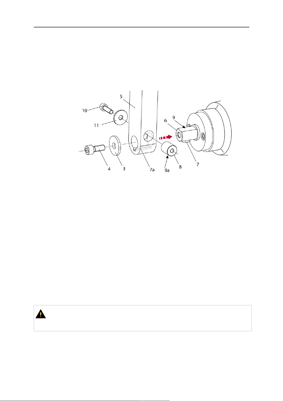
5. Place the torch mount (5) onto the journal (6) of the mounting flange, paying attention
while doing so to the exact alignment of the feather key (7) and the corresponding
groove (7a).
6. Insert the clamping mandrel (8) into the lateral hole (see illustration) and position it so
that the mating surfaces (9a) of the clamping mandrel rest on the mating surface (9) of
the journal.
0463 373 101
- 27 -
© ESAB AB 2018

5 INSTALLATION
7. Fix the clamping mandrel from the opposite side using the M6 cylinder screw with
hexagon socket (10) and the Ø22 mm washer (11).
8. Screw the axial cylinder screw (4) with the Ø9 mm washer (3) into the mounting flange
and tighten firmly.
3 - Washer Ø9 mm 8 - Clamping mandrel
4 - Axial cylinder screw with hexagon
9 - Mating surface of mounting flange
socket M8×16
5 - Torch mount 9a - Mating surfaces of clamping mandrel
6 - Mounting flange journal 10 - Cylinder screw with hexagon socket
M6×30
7 Feather key 11 - Washer Ø22×6.4 mm
7a - Groove for feather key
5.1.2 Standard arm cable assembly for KS-2 and FL-2
The cable assembly must be aligned to the intended use in length and design. The type of
cooling for the torch and the cable assembly must be the same (either gas or water cooled
respectively). In order to prevent damage to the torch system and other components, it is
imperative to observe the following instructions.
0463 373 101
- 28 -
© ESAB AB 2018

5 INSTALLATION
PRZESTROGA!
• Coordinate the length and design of the cable assembly to suit the range of
action of the robot.
• Do not bend, compress or overstretch the cable assembly.
• Fix the cable assembly such that is can be moved freely and cannot become
entangled.
• Any additional holding devices possibly installed, for example a balancer,
must not crush or bend the cable assembly.
• Extreme turning movements must be avoided in which the cable assembly
may become twisted.
• Chafing on the robot or other objects must be excluded.
1. Unscrew the cylinder screws (1) and lift off the top section (2) of the torch mount.
2. Insert the feather key (4) into the recess of the neck support flange (3) from below.
3. Align the neck support flange (3) including the feather key (4) to the groove (5) of the
torch mount and push into the groove right up to the stop of the flange.
4. Hold the cable assembly in this position and simultaneously place the top section (2)
back onto the torch mount. First screw both cylinder screws (1) loosely in to about the
same length, then tighten alternately. The top section (2) of the mount should have an
even gap to the bottom section.
The front part of the cable assembly is directly clamped into the torch mount (see
illustration below).
1 - Cylinder screws 4 - Feather key
2 - Torch mount top section 5 - Groove for feather key
3 - Neck support flange
5.1.3 RTKS-2 wire feeder connection
In order to be able to create the connection, the cable assembly must be mounted as
described in the "Installing the cable assembly" section and equipped following "Installing the
wire guide" section. Only then can the central and media connection take place. Proceed as
described below:
0463 373 101
- 29 -
© ESAB AB 2018

5 INSTALLATION
1. Connect the central connector of the cable assembly (2) to the wire feeder cabinet
socket. Tighten the central connector sleeve nut fingertight. Do not use tools.
1 - Burndy Connector 4 - Return of heated water (red cap)
2 - EURO central connector 5 - Return of heated water (red cap)
3 - Air blow-out 6 - Main Wire feeder
2. For water cooled systems. Connect the water hoses to the cooling circuit. The end of
the hose marked blue (4) is connected to the water outlet, and the end marked red (5)
is connected to the water return.
3. Connect the blow-out line (3) to the corresponding connection of the feeder.
4. Connect the Burndy Connector to the wire feeder. (1) to the feeder. See section
"Electrical connections".
UWAGA!
All hoses and the control line must be installed so they can not bend or get
damaged!
5.1.4 RTKS-2 electrical connections
5.1.4.1 RTKS-2 safety-off mechanism connection
The switch for the safety-off functionality RTKS-2 is connected through the control cable,
see (3) in the illustration below. This connects to the RTKS-2 unit via the 4-pole plug (4) that
contains circuits for the push-button (6) and the safety-off signal (7).
If a collision is detected, the control circuit for the safety-off signal (7), which is normally
closed, will be interrupted.
Rating of the control circuit: max. 48 V / 1 A
0463 373 101
- 30 -
© ESAB AB 2018

5 INSTALLATION
2 - Burndy connector 5 - RTKS-2 connector for control cable plug
4 - Control cable plug
Styki złącza Burndy
A. Dysza gazowa Touch
sense
C. Czujnik kolizji
F. 0V
G. + Napięcie silnika
H. - Napięcie silnika
D. Czujnik kolizji
E. Wprowadzanie
If the robot control provides a control circuit for nozzle sense functionality, the connection is
accomplished with a 1-wire connection.
Rating of the control circuit: max 50 V / 5 A.
NIEBEZPIECZEŃSTWO!
If the nozzle sense function is not being used, the open end of the control cable on
the power source connection side must be properly isolated in order to avoid short
circuits. During certain problems on the torch head, the full welding potential may be
present on this cable.
PRZESTROGA!
After detection of contact (gas nozzle on work piece), quickly reduce or cut off the
maximum current in the nozzle sense circuit in order to avoid overloading of the
system.
Allowed load max. 1 minute at the rated nominal current.
5.1.5 RTKS-2 Torch installation
Continue according to section "Torch installation".
0463 373 101
- 31 -
© ESAB AB 2018

5 INSTALLATION
5.2 RTFL-2 standard arm installation
5.2.1 RTFL-2 rigid mount
1. Position the RT FL-2 (2) with the index pin on the robot arm and fix it with the hexagon
socket screw included.
The FL-2 is directly compatible with robots with tool flange according to DIN ISO
9409-1-A40 (diameter 40mm, 4×M6). If the rigid mount does not fit, use an adapter
flange (3).
UWAGA!
Ensure that the index pin is located correctly. The maximum torque of 1.2Nm
(10.5in.lb) must be observed for the fastening of the adapter flange screws.
Prevent self-loosening of the screws by using suitable thread locking
measures.
2. Install torch mount (1). Only torch mounts having a hole pattern equivalent with the
mounting surface may be attached. If necessary, carefully press the cylindrical pins (4)
into the corresponding holes in the bracket. The pins should protrude by
approximately 5mm (0.2in.). Position the torch mount on the RTFL-2 (2) and
carefully insert the cylindrical pins (4) into the holes provided. Take the position of the
torch into account. Two mounting positions may be potentially possible.
3. Screw the mount evenly using the enclosed cylinder screws with hexagon socket (5).
UWAGA!
The maximum tightening torque for the cylinder screw (5) is 6Nm (53in.lb)
and the property class category is 8.8.
0463 373 101
- 32 -
© ESAB AB 2018

5 INSTALLATION
4 - Cylindrical pins Ø4×20
5 - Cylinder screw with hexagon socket M6
DIN 912 (length of the screw depending on
the torch mount)
Side view
Torch installation with adjustable mount
Torch mounts with a central clamping assembly can only be fastened on the journal of the
mounting flange. For this, the mounting flange must be fastened first.
1. If applicable, carefully press the cylindrical pins (1) into the corresponding holes in the
mounting flange. Avoid the formation of burrs. The pins should protrude by
approximately 5 mm (0.2 in.).
2. Position the mount on the RTFL-2 and carefully insert the cylindrical pins (1) into the
holes provided. In doing so, take the later position of the torch into account. Two
mounting positions may be potentially possible.
3. Then screw down the mounting flange evenly using the enclosed cylinder screws with
hexagon socket (2).
UWAGA!
The maximum tightening torque for the cylinder screw (2) is 7.1 Nm (62.8
in.lb) and the property class category is 8.8.
4. Unscrew the axial cylinder screw with hexagon socket (4) out of the mounting flange
together with the washer (3).
1 - Cylindrical pins Ø4×14 3 - Washer Ø9 mm
2 - Cylinder screw with hexagon socket
M6×16
4 - Axial cylinder screw with hexagon
socket M8×16
5. Place the torch mount (5) onto the journal (6) of the mounting flange, paying attention
while doing so to the exact alignment of the feather key (7) and the corresponding
groove (7a).
0463 373 101
- 33 -
© ESAB AB 2018
5 INSTALLATION
6. Insert the clamping mandrel (8) into the lateral hole (see illustration) and position it so
that the mating surfaces (9a) of the clamping mandrel rest on the mating surface (9) of
the journal.
7. Fix the clamping mandrel from the opposite side using the M6 cylinder screw with
hexagon socket (10) and the Ø22 mm washer (11).
8. Screw the axial cylinder screw (4) with the Ø9 mm washer (3) into the mounting flange
and tighten firmly.
3 - Washer Ø9 mm 8 - Clamping mandrel
4 - Axial cylinder screw with hexagon
9 - Mating surface of mounting flange
socket M8×16
5 - Torch mount 9a - Mating surfaces of clamping mandrel
6 - Mounting flange journal 10 - Cylinder screw with hexagon socket
M6×30
7 - Feather key 11 - Washer Ø22×6.4 mm
7a - Groove for feather key
5.2.2 RTFL-2 torch installation
Continue according to section "Torch installation".
5.3 RTKSC-2 hollow wrist system installation
5.3.1 RTKSC-2 mount with safety off mechanism
PRZESTROGA!
For hollow wrist systems make sure that the clear space around the robot is at least
Ø45 mm (1.8 in.) around the wrist and 50 mm (2.0 in.) near the wire feeder.
0463 373 101
- 34 -
© ESAB AB 2018

5 INSTALLATION
1. Remove the three screws (2) from the front cover (3) of the torch mount and carefully
pull the cover off the RTKSC-2 main body (5). Take care not to damage the micro
switches installed inside the assembly.
1 - Hexagon wrench 4 mm 4 - Rubber boot
2 - 3× M5×12 screws 5 - RT KSC-2 main body
3 - RT KSC-2 front cover
1. Pull off the rubber boot (4) from the RTKSC-2 main body (5) to the front.
2. Now position the RTKSC-2 main body (5) on the adapter flange (7) so that the index
pin is correctly seated. Attach with the screws (6) enclosed.
3. Reinstall the rubber boot (4) on the RTKSC-2 main body (5) and make sure it is
correctly located in the grooves on the front and back flange.
4. Istall the adapter flange (7) on the robot.
Fastening torque max. 2.2 Nm (19.5 in.lb).
1 - Hexagon wrench 4 mm 3 - 3× M5×12 hexagon socket screws
2 - Rubber boot 4 - Adapter flange
5.3.2 Mounting the cable assembly
UWAGA!
In order to adjust the wire feeder position to the cable assembly length, it must be
mounted on an adjustable support with a possible movement of ±2-3cm (±1in.) to
the back and to the front. The length of the cable assembly must be determined
from the centred mounting position of the wire feeder.
1. Move the robot arm into a completely straight position, see illustration below. Make
sure that (1) axis 6 (rotation around the torch axis) is in 0° position.
2. Move the feeder (3) completely to the back in order to create space for inserting the
cable assembly. If it is not possible to move the feeder sufficiently, it should be
removed from the robot.
0463 373 101
- 35 -
© ESAB AB 2018

5 INSTALLATION
3. Insert the cable assembly with the coupling (2) first into the robot arm and feed it
through the robot wrist.
4. The feeder should only be installed again after the correct mounting position with
respect to the cable length has been determined. (See section "Installing the cable
assembly").
PRZESTROGA!
Axis 6 must be in 0° position.
5.3.2.1 RTKSC-2 feeder cabinet connections
When installed for the first time, the position of the wire feeder cabinet must be adjusted to
the length of the cable assembly. First, the robot arm must be fully extended (straight).
PRZESTROGA!
As long as the correct position of the feeder corresponding to the length of the cable
assembly has not been determined, be careful when moving the robot arm and
avoid overstretching the cable. It is helpful to loosen the positioning screws of the
feeder before moving the robot arm to allow the feeder to follow the cable assembly.
0463 373 101
- 36 -
© ESAB AB 2018

5 INSTALLATION
1. Loosen the sliding mechanism of the wire feeder and connect the cable assembly.
2. Now adjust the position of the wire feeder to suit the length of the Infiniturn or Helix
cable, as indicated with "A" in the illustration below.
PRZESTROGA!
When adjusting the position of the feeder cabinet, make sure that the cable
assembly is not under stress when the robot arm is in stretched-out position.
It is normal for the cable assembly to sag slightly, it should never be taut.
3. Before securing the wire feeder in its permanent position, ensure that the Euro
connectors are tightly connected. Then turn the torch mount down and up again
(rotating on the axis 5), in order not to tighten the cable assembly too much against
the feeder (see illustration above). Once this is done, tighten the feeder in that
position.
4. For water cooled systems, connect the water lines to the cooling circuit. See section
"Cable assemblies for hollow wrist systems" in the TECHNICAL DATA chapter for
indications.
The hose with the blue rubber cap is for cooling water to the torch, the hose with the
red rubber cap returns the heated water. Make sure the hoses will not kink or get
otherwise blocked.
UWAGA!
A Helix cable assembly used for a gas cooled system must not be connected
to a cooling circuit. As the water connections are not needed, they may be cut
off.
5. Connect the blow-out hose (black rubber cap) to the corresponding outlet of the wire
feeder.
UWAGA!
If the blow-out function is not used, the blow-out hose must be sealed with the
rubber cap enclosed. With Infiniturn systems, the blow-out air must be
supplied to the corresponding connection hose, if it is not permitted to connect
blow-out air to the shield gas connection!
6. Install the necessary plug on the control cable and connect it to the safety off circuit
interface of the wire feeder (see section "Electrical connections").
0463 373 101
- 37 -
© ESAB AB 2018

5 INSTALLATION
5.3.3 RTKSC-2 cable assembly
The cable assembly must be aligned to the intended use in length and design. The type of
cooling for the torch and the cable assembly must be the same (either gas or water cooled
respectively). In order to prevent damage to the torch system and other components, it is
imperative to observe the following instructions.
PRZESTROGA!
• Coordinate the length and design of the cable assembly to suit the range of
action of the robot.
• Do not bend, compress or overstretch the cable assembly.
• Fix the cable assembly such that is can be moved freely and cannot become
entangled.
• Any additional holding devices possibly installed, for example a balancer,
must not crush or bend the cable assembly.
• Extreme turning movements must be avoided in which the cable assembly
may become twisted.
• Chafing on the robot or other objects must be excluded.
5.3.3.1 RTKSC-2 cable assembly installation
UWAGA!
For some robots, it may be possible to deviate from this order, and first connect the
cable assembly to the RTKSC-2, then thread the cable from the front through the
robot arm. If in doubt, follow the suggested order.
1. Loosen the three screws (7) with the associated washers and remove them from the
RTKSC-2 cover (1). See illustration below.
2. Install the supplied O-rings (4) into the grooves in the cover (1).
3. Pull the cable assembly approximately 15 cm (6 in.) from the main body (3).
0463 373 101
- 38 -
© ESAB AB 2018

5 INSTALLATION
4. Insert the coupling (2) into the socket of the cover (1) as shown. Align the index pin (6)
with the index hole (5) in the main body and insert completely.
UWAGA!
Make sure that the position of the O-rings are not shifted by the index pin
during the assembly.
1 - RTKSC-2 cover 5 - Index hole
2 - Coupling 6 - Index pin
3 - RTKSC-2 main body 7 - 3× M5×35 screws
4 - 3× O-ring for water cooled systems 11 - Control cable connector
5. Insert the three screws (7) with the associated washers (8) and tighten gently with the
enclosed hexagonal wrench, see below illustration.
Fastening torque approximately 2 Nm (18 in.lb).
0463 373 101
- 39 -
© ESAB AB 2018

5 INSTALLATION
6. If present, insert the control cable plug (10) into the connector (11) and make sure it is
firmly seated.
7 - 3× M5×35 screw 11 - Control cable connector
8 - Washer 12 - 2× Micro switch
10 - Control cable plug 13 - Index pin
7. Gently push back the cable assembly into the robot arm and carefully seat the
RTKSC-2 cover (1) in place. Observe the index pin (13) to be in the correct position.
Make sure the two micro switches (12) are not damaged if present.
8. Insert the three M5 screws (14) and tighten without excessive force.
13. Index pin
14. 3× M5×12 screws
0463 373 101
- 40 -
© ESAB AB 2018

5 INSTALLATION
5.3.3.2 RTKSC-2 electrical connections
UWAGA!
After connecting the control cable, secure the cable in order to protect it from getting
caught while the robot is moving.
Usually, the control cable will be directly connected to the wire feeder. See the
manufacturer's documentation for details. The link to the robot control is then
implemented via the power source controller.
RTKSC-2 safety-off mechanism connection
The switch for the safety-off functionality RTKSC-2 is connected through the control cable,
see (3) in the illustration below. This connects to the RTKSC-2 unit via the control cable plug
(1).
The safety-off signal requires a 2-wire connection (black/black) to the safety-off circuit in the
robot control (5).
If a collision is detected, the control circuit (normally closed) will be interrupted (4).
Rating of the control circuit: max. 48 V / 1 A.
1 - Control cable plug 3 - Burndy connector VVV
2 - EURO central connector
Styki złącza Burndy
A. Dysza gazowa Touch
sense
C. Czujnik kolizji
F. 0V
G. + Napięcie silnika
H. - Napięcie silnika
D. Czujnik kolizji
E. Wprowadzanie
RTKSC-2 nozzle sense function connection
If the robot control provides a control circuit for nozzle sense functionality.
The connection is accomplished with a 2-wire connection (black/black) to the nozzle sense
circuit in the robot control (5), see illustration below.
0463 373 101
- 41 -
© ESAB AB 2018

5 INSTALLATION
Usually, the control cable will be directly connected to the wire feeder. See the
manufacturer's documentation for details. The link to the robot control is then implemented
via the power source robot interface.
Rating of the control circuit: max. 50 V / 5 A.
NIEBEZPIECZEŃSTWO!
If the nozzle sense function is not being used, the open end of the control cable on
the power source connection side must be properly isolated in order to avoid short
circuits. During certain problems on the torch head, the full welding potential may be
present on this cable.
PRZESTROGA!
After detection of contact (gas nozzle on work piece), quickly reduce or cut off the
maximum current in the nozzle sense circuit in order to avoid overloading of the
system.
Allowed load max. 1 minute at the rated nominal current.
1 - Control cable plug 3 - Control cable
2 - EURO central connector
5.3.4 RTKSC-2 torch installation
Continue according to section "Torch installation".
0463 373 101
- 42 -
© ESAB AB 2018

5 INSTALLATION
5.4 RTFLC-2 installation
5.4.1 RTFLC-2 mount
1. Remove the three M5 screws (2) from the front cover (3) of the RT FLC-2 torch mount
and carefully pull the cover off the main body (4).
1 - Hexagon wrench 4 mm 3 - RT FLC-2 front cover
2 - 3× M5×12 screws 4 - RT FLC-2 main body
2. Now position the RT FLC-2 main body (4) on the adapter flange (6) so that the index
pin is correctly seated. Attach with the screws (5) enclosed
Fastening torque max. 2.2 Nm (19.5 in.lb).
1 - Hexagon wrench 4 mm 5 - 3× M5×12 hexagon socket screws
4 - RT FLC-2 main body 6 - Adapter flange
5.4.2 RTFLC-2 wire feeder connection
5.4.2.1 Feeding through the robot arm
UWAGA!
In order to adjust the wire feeder position to the cable assembly length, it must be
mounted on an adjustable support with a possible movement of ± 2-3 cm (± 1 in.) to
the back and to the front. The length of the cable assembly must be determined
from the centred mounting position of the wire feeder.
0463 373 101
- 43 -
© ESAB AB 2018

5 INSTALLATION
1. Move the robot arm into a completely straight position, see illustration below. Make
sure that (1) axis 6 (rotation around the torch axis) is in 0° position.
2. Move the feeder (3) completely to the back in order to create space for inserting the
cable assembly. If it is not possible to move the feeder sufficiently, it should be
removed from the robot.
3. Insert the cable assembly with the coupling (2) first into the robot arm and feed it
through the robot wrist.
4. The feeder should only be installed again after the correct mounting position with
respect to the cable length has been determined. (See section "Installing the cable
assembly").
PRZESTROGA!
Important! Axis 6 must be in 0° position.
5.4.2.2 RTFLC-2 feeder cabinet connections
When installed for the first time, the position of the wire feeder cabinet must be adjusted to
the length of the cable assembly. First, the robot arm must be fully extended (straight).
PRZESTROGA!
As long as the correct position of the feeder corresponding to the length of the cable
assembly has not been determined, be careful when moving the robot arm and
avoid overstretching the cable. It is helpful to loosen the positioning screws of the
feeder before moving the robot arm to allow the feeder to follow the cable assembly.
0463 373 101
- 44 -
© ESAB AB 2018

5 INSTALLATION
1. Loosen the sliding mechanism of the wire feeder and connect the cable assembly.
Refer to the instruction of the feeder manufacturer.
2. Now adjust the position of the wire feeder to suit the length of the Infiniturn or Helix
cable, as indicated with "A" in the illustration below.
PRZESTROGA!
When adjusting the position of the feeder cabinet, make sure that the cable
assembly is not under stress when the robot arm is in stretched-out position.
It is normal for the cable assembly to sag slightly, it should never be taut.
3. Before securing the wire feeder in its permanent position, ensure that the Euro
connections are tightly connected. Then turn the torch mount down and up again
(rotating on the axis 5), in order not to tighten the cable assembly too much against
the feeder (see illustration above). Once this is done, tighten the feeder in that
position.
4. For water cooled systems, connect the water lines to the cooling circuit. See section
"Cable assemblies for hollow wrist systems" in the TECHNICAL DATA chapter for
indications.
The hose with the blue rubber cap is for cooling water to the torch, the hose with the
red rubber cap returns the heated water. Make sure the hoses will not kink or get
otherwise blocked.
UWAGA!
A Helix cable assembly used for a gas cooled system must not be connected
to a cooling circuit. As the water connections are not needed, they may be cut
off.
5. Connect the blow-out hose (black rubber cap) to the corresponding outlet of the wire
feeder.
UWAGA!
If the blow-out function is not used, the blow-out hose must be sealed with the
rubber cap enclosed. With Infiniturn systems, the blow-out air must be
supplied to the corresponding connection hose, if it is not permitted to connect
blow-out air to the shield gas connection!
0463 373 101
- 45 -
© ESAB AB 2018

5 INSTALLATION
6. Install the necessary plug on the control cable and connect it to the safety off circuit
interface of the wire feeder (see section "Electrical connections").
5.4.3 RTFLC-2 cable assembly
The cable assembly must be aligned to the intended use in length and design. The type of
cooling for the torch and the cable assembly must be the same (either gas or water cooled
respectively). In order to prevent damage to the torch system and other components, it is
imperative to observe the following instructions.
PRZESTROGA!
• Coordinate the length and design of the cable assembly to suit the range of
action of the robot.
• Do not bend, compress or overstretch the cable assembly.
• Fix the cable assembly such that is can be moved freely and cannot become
entangled.
• Any additional holding devices possibly installed, for example a balancer,
must not crush or bend the cable assembly.
• Extreme turning movements must be avoided in which the cable assembly
may become twisted.
• Chafing on the robot or other objects must be excluded.
5.4.3.1 RTFLC-2 cable assembly installation
In a hollow wrist system the recommended order of installation is to feed the cable assembly
through the robot arm before connecting the cables to the torch mount.
When the cable assembly is correctly installed in the hollow wrist, continue the installation
according to the procedure described below.
UWAGA!
For some robots, it may be possible to deviate from this order, and first connect the
cable assembly to the RTKSC-2 and RTFLC-2, then thread the cable from the front
through the robot arm. If in doubt, follow the suggested order.
1. Loosen the three screws (7) with the associated washers and remove them from the
RTFLC-2 cover (1). See illustration below.
2. Install the supplied O-rings (4) into the grooves in the cover (1). For gas cooled
systems, only one O-ring (4a) is needed, for water cooled systems all three O-rings
are needed.
3. Pull the cable assembly approximately 15 cm (6 in.) from the main body (3).
0463 373 101
- 46 -
© ESAB AB 2018

5 INSTALLATION
4. Insert the coupling (2) into the socket of the cover (1) as shown. Align the index pin (6)
with the index hole (5) in the main body and insert completely.
UWAGA!
Take great care that the position of the O-rings is not shifted by the index pin
during the assembly.
1 - RT FLC-2 cover 5 - Index hole
2 - Coupling 6 - Index pin
3 - RT FLC-2 main body 7 - 3× M5×35 screws
4 - 3× O-ring for water cooled systems 11 - Control cable connector
5. Insert the three screws (7) with the associated washers (8) and tighten gently with the
enclosed hexagonal wrench, see below illustration.
Fastening torque approximately 2 Nm (18 in.lb).
0463 373 101
- 47 -
© ESAB AB 2018

5 INSTALLATION
6. If present insert the control cable plug (10) into the connector (11) and make sure it is
firmly seated.
7 - 3× M5×35 screw 11 - Control cable connector
8 - Washer 12 - 2× Micro switch
10 - Control cable plug 13 - Index pin
7. Gently push back the cable assembly into the robot arm and carefully seat the
RTFLC-2 cover (1) in place. Observe the index pin (13) to be in the correct position.
Make sure the two micro switches (12) are not damaged if present.
8. Insert the three M5 screws (14) and tighten without excessive force.
13 - Index pin 14 - 3x M5x12 screws
0463 373 101
- 48 -
© ESAB AB 2018

5 INSTALLATION
5.4.4 RTFLC-2 electrical connections
UWAGA!
After connecting the control cable, secure the cable in order to protect it from getting
caught while the robot is moving.
Usually, the control cable will be directly connected to the wire feeder. See the
documentation of the manufacturer for details. The link to the robot control is then
implemented via the power source controller.
5.4.4.1 RTFLC-2 hollow wrist system with Infiniturn cable assembly
Connecting the nozzle sense function
If the robot control provides a control circuit for nozzle sense functionality.
The connection is accomplished with a 2-wire connection (black/black) to the nozzle sense
circuit in the robot control (5), see illustration below.
Usually, the control cable will be directly connected to the wire feeder. See the
manufacturer's documentation for details. The link to the robot control is then implemented
via the power source robot interface.
Rating of the control circuit: max. 50 V / 5 A.
NIEBEZPIECZEŃSTWO!
If the nozzle sense function is not being used, the open end of the control cable on
the power source connection side must be properly isolated in order to avoid short
circuits. During certain problems on the torch head, the full welding potential may be
present on this cable.
PRZESTROGA!
After detection of contact (gas nozzle on work piece), quickly reduce or cut off the
maximum current in the nozzle sense circuit in order to avoid overloading of the
system.
Allowed load max. 1 minute at the rated nominal current.
1 - Control cable plug 3 - Control cable
2 - EURO central connector
0463 373 101
- 49 -
© ESAB AB 2018

5 INSTALLATION
5.4.4.2 RTFLC-2 hollow wrist system with Helix cable assembly
Connecting the nozzle sense function
If the robot control provides a control circuit for nozzle sense functionality.
The connection is accomplished with a 1-wire connection (green) to the nozzle sense circuit
in the robot control (5), see illustration below.
Usually, the control cable will be directly connected to the wire feeder. See the
manufacturer's documentation for details. The link to the robot control is then implemented
via the power source robot interface.
Rating of the control circuit: max. 50 V / 5 A.
NIEBEZPIECZEŃSTWO!
If the nozzle sense function is not being used, the open end of the control cable on
the power source connection side must be properly isolated in order to avoid short
circuits. During certain problems on the torch head, the full welding potential may be
present on this cable.
PRZESTROGA!
After detection of contact (gas nozzle on work piece), quickly reduce or cut off the
maximum current in the nozzle sense circuit in order to avoid overloading of the
system.
Allowed load max. 1 minute at the rated nominal current.
1 - Control cable plug 3 - EURO central connector
2 - Control cable 4 - Burndy connector
5.5 Torch installation
Be sure to use the correct version of the torch mount and cable assembly (water or gas
cooled).
5.5.1 Torch neck equipment
The torch neck, see (1) in the illustration below, must always be equipped to suit the wire
diameter and material.
0463 373 101
- 50 -
© ESAB AB 2018

5 INSTALLATION
1. Select the correct wire guide, contact tip (4), tip holder (2), gas nozzle (5), and gas
diffuser/spatter protection (3). You will find an exact overview and possible alternative
equipment elements for various torch models in the spare parts list. Only use original
ESAB parts; only then is the fitting accuracy ensured.
2. Firmly tighten the tip holder and the contact tip using a suitable tool for example the
enclosed monkey wrench.
3. When using a split wire guide, remove the installed guide nipple including the o-ring
from the torch flange upon delivery if necessary (see section "Installing the neck
liner").
PRZESTROGA!
The torch must be completely equipped before welding, especially the gas
diffuser and/or spatter protection and all necessary insulators have to be
installed according to the spare parts list. Welding without these items may
cause immediate destruction of the torch.
1 - Torch neck 4 - Contact tip
2 - Tip holder 5 - Contact tip
3 - Gas diffuser
5.5.2 Aristo RT torch neck installation
UWAGA!
Check the O-rings on the flange of the torch neck before mounting. Replace the
O-rings if damaged or lost. Missing or faulty O-rings will lead to leaks of shielding
gas and coolant.
1. For hollow wrist systems, insert the torch into the torch mount in the correct
orientation, so that the locator pin fits into the slot of the RTKSC-2 or RTFLC-2
interface, see (A) in the illustration below. For standard systems, attach the torch to
the RT flange of the cable assembly, (B) in the illustration below.
Installation is only possible in the correct orientation.
2. Tighten the locking nut of the torch neck.
UWAGA!
Only tighten by hand, never use tools or excessive force.
0463 373 101
- 51 -
© ESAB AB 2018

5 INSTALLATION
3. The correct seating of the torch can be checked by means of the window (1). If the
torch has been correctly mounted, no gap should be seen through the window (1).
5.6 Installing the wire guide for standard and hollow Wrist arm
Installing the wire guide
Choose the wire guide or liner depending on the filler wire material and diameter to be used,
see the spare parts list. Accurate performance of the system can only be guaranteed when
using original ESAB wire guides.
The recommended wire guide is the split wire guide, which consists of the neck liner and a
separate guide in the cable assembly. The front part of the wire guide, which is most
stressed, can be exchanged easily and independently of the cable assembly wire guide.
For correct installation, the following steps must be followed (example for Euro central
connector).
5.6.1 Installing the neck liner
The neck liner must be selected to fit the material and diameter of the welding wire, see the
spare parts list.
0463 373 101
- 52 -
© ESAB AB 2018

5 INSTALLATION
1. If present, remove the central guide nipple (1), from the torch neck using a hexagon
wrench (size 6 mm) or a large flat-blade screwdriver.
UWAGA!
The guide nipple (1) can only be used with one-piece liners and must not be
used with the standard RT or hollow wrist system.
2. When replacing the neck liner:
Unfasten the sleeve nut and remove the torch neck.
Unfasten the liner nipple using a hexagon wrench (size 6 mm) and remove nipple and
liner from the torch neck.
3. Remove the gas nozzle and the contact tip.
4. Insert the new neck liner (2) into the torch. Carefully tighten the guide nipple using a
suitable tool, e.g. a hex-wrench (size 6 mm) or a large flat-blade screwdriver.
5. Cut the neck liner flush with the tip holder and remove the neck liner from the torch.
6. Install the contact tip.
7. Insert the neck liner again. It will be stopped by the contact tip. Measure the excess
liner sticking out of the neck.
8. Remove the liner again and shorten the front end by the measured length. Carefully
deburr the edge and make sure that the inner hole is not blocked.
9. Reinstall the neck liner and tighten the guide nipple in the neck.
5.6.2 Installing a split wire guide in the cable assembly
The correct liner must be inserted to suit the filler material and the wire diameter, see the
spare parts list.
The wire guide is inserted through the cable assembly from the rear, reaching the guide
nipple that is installed in the flange where the torch neck will be attached. The following
worksteps must be followed in order to correctly determine the wire guide length. (Example
for Euro central connector).
0463 373 101
- 53 -
© ESAB AB 2018

5 INSTALLATION
1. For standard RT system: Install the guide nipple (1) in the center hole of the neck
support flange, see illustration A below.
For hollow wrist system: Install the guide nipple (1) into the torch interface of the
RTKSC-2 / RTFLC-2 cover, see illustration B below.
2. Remove the sleeve nut (2) from the central connector, and remove the old wire guide.
3. Insert the wire guide through the central connection and push forwards as far as it will
go into the guide nipple (1), applying light pressure.
PRZESTROGA!
Ensure that the wire guide has advanced right up to the stop at the front,
rotating and pushing forward gently.
4. Measure the excess length that needs to be cut from the wire guide.
5. Remove the wire guide again and shorten the front end by the measured length.
Steel liner: grind down the burred edges if needed.
Plastic liner: make a clean cut and chamfer the edges (e.g. with a pencil sharpener)
UWAGA!
Make sure the inner opening of the liner is not obstructed by the cut wire end.
0463 373 101
- 54 -
© ESAB AB 2018

5 INSTALLATION
6. Reinstall the wire guide and attach the sleeve nut (2).
UWAGA!
For hollow wrist systems where Infiniturn and Helix cable assemblies are
used, wire guides should be installed without tension so that the ends of the
liners may rotate freely.
Important note when using a plastic liner:
The wire channel between the drive rolls of the feeder and the central
connector of the torch must be fitted with a plastic liner. Depending on the
design of the feeder, a piece of plastic liner inserted into a brass guide tube
can be used.
During wire run-in, make sure that the wire is fed correctly into the plastic liner
of the torch. If necessary, remove the cable assembly from the feeder and
insert the wire, then reattach.
5.6.3 Installing a continuous wire guide in the cable assembly
Installing a steel liner
The wire guide is inserted through the cable assembly from the rear and reaches to the
contact tip. The following worksteps must be followed for the correct calculation of the length
(example for Euro central connector):
1. Install the torch (see section "Torch neck equipment").
2. Remove the gas nozzle and contact tip from the torch.
3. Remove the sleeve nut (D) from the Euro connector.
4. Push in the liner through the central connector and fix with the sleeve nut.
5. Cut off the liner flush with the nozzle holder. To determine the thread projection of the
contact tip, pull the liner backwards and screw in the contact tip.
6. Push the liner forwards as far as it will go to the contact tip applying light pressure on
the liner and measure the length to be shortened at the rear.
7. Now remove the liner again and cut the excess length measured off it’s front end. If
needed, grind down the burred edges. Make sure the inner opening of the liner is not
obstructed by the cut wire end.
8. The insulation of the liner must be removed after cutting off in the front area, such that
the insulation protrudes out of the RM2 flange by approx. 5 cm. For this, briefly
remove the torch neck.
9. Push the liner back in again and fix with the sleeve nut (D), see above. Re-install the
gas nozzle.
0463 373 101
- 55 -
© ESAB AB 2018

5 INSTALLATION
Installing a plastic liner
1. Mount the torch neck (see section "Torch neck equipment") and equip it with a gas
nozzle and contact tip.
2. Remove the sleeve nut (D) from the Euro connector.
3. Cleanly cut off the liner, slightly break the outer edges, point slightly (e.g. with a pencil
sharpener).
4. Insert the liner through the central connector into the cable assembly with fitted torch.
If it gets stuck, rotate the liner to free it and facilitate installation.
UWAGA!
Make sure the liner is completely inserted by rotating it and slightly pushing it
forward, until you can feel it has reached its stop.
5. Mount the nipple (B) and the O-Ring (C), move it to the right position and fix it with the
sleeve nut (D) of the Euro central connector.
6. Measure the required overlap needed inside the wire feeder cabinet and cut the liner
accordingly.
5.7 Adjust the narrow gap contact tip
The adjusting tool RT42-NG is designed for the narrow gap torch necks RT42W-NG,
RT42G-NG and RT 82W-0°NG, torches with curved narrow gap contact tip. It facilitates the
precisely repeatable and fast changing of the curved contact tip.
UWAGA!
The adjusting tool must be securely fastened to a stable base, in order to prevent
the position of the device in relation to the robot cannot change unintentionally. If the
exact orientation of the device is lost, the alignment of the contact tip used for the
elaboration of the welding programs can no longer be reproduced with precision.
Select a position within the operating range of the robot for orientation (alignment) of the
contact tip to the torch. Fasten the adjusting tool firmly to a base using the fastening grooves
provided for this purpose. Fastening material is not included with the adjusting tool. Select
fastening material (screws) to suit the existing conditions.
Save all motion sequences and stop positions required to change or align the wearing parts
to a separate robot program.
Before programming the welding tasks: plan at which orientation the contact tip is to stand in
relation to the torch. The torch must then be positioned in the desired rotational position and
the contact tip aligned using the adjusting device. Only then may the welding task be
programmed. If different orientations of the contact tip are required for various welding tasks,
the contact tip has to be aligned to the new position when the welding task is changed.
OSTRZEŻENIE!
The gas nozzle and the torch head become very hot during welding. Always allow
the torch to cool down before replacing wearing parts or adjusting the contact tip.
0463 373 101
- 56 -
© ESAB AB 2018

5 INSTALLATION
Adjust the contact tip
Move the robot torch to a position parallel to
the opening of the adjusting tool (2). Maintain
a sufficient distance to the work table to be
able to comfortably remove the gas nozzle.
Define this position in your robot program as
the wearing parts change position (stop
position 1).
Remove the gas nozzle by pulling it
downwards. Remove the welding wire in the
contact tip if necessary.
Loosen the counter nut (4) of the contact tip
while counter-holding the nozzle holder at the
wrench flat (3).
Unscrew the contact tip including the counter
nut from the nozzle holder and replace the
nozzle holder if necessary.
Completely screw the counter nut (4) onto the
new contact tip. Screw the contact tip
including the counter nut into the nozzle
holder.
Align the contact tip until it is parallel to the
opening of the adjusting tool. If necessary,
slightly unscrew the contact tip so that it can
be easily turned in both directions.
0463 373 101
- 57 -
© ESAB AB 2018

5 INSTALLATION
UWAGA!
The contact tip must be able to be
easily moved by hand in both
directions in order to enable the
threading of the adjusting tool.
Place the robot torch or contact tip directly in
front of the opening of the adjusting tool (2)
(stop position 2).
Insert it slowly from the front until it is
completely inserted into the device (stop
position 3).
The contact tip was aligned exactly in the
device during insertion. Now cautiously
tighten the counter nut (4) in this position,
while counter holding the nozzle holder at the
wrench flat.
Slowly move the robot torch out of the
adjusting gauge, return to stop position 1 and
push on the gas nozzle as far as it will go.
Allow the welding wire to run into the contact
tip and bring the robot arm into welding
position.
0463 373 101
- 58 -
© ESAB AB 2018

6 OPERATION
6 OPERATION
PRZESTROGA!
Before starting the system, check the whole installation according to the
manufacturer's instructions and applicable safety regulations.
Check the following to make sure that the system has been installed correctly:
1. Are all parts securely attached (torch, torch mount, flanges, safety-off device, cable
assembly, and wire feeder cabinet)?
2. Are all media hoses connected correctly and protected from damage?
3. Is the EURO central connector or direct connector fastened tightly?
4. Is the cable assembly length correct and suitable for the installation and can the cable
rotate freely? The cable must not be bent sharply. Any risk of the cable getting caught
on another object must be eliminated.
5. Is the control cable of the safety-off circuit connected and functioning? Move torch by
hand to test (RTKSC-2 and RTKS-2 only).
6. Is the torch firmly attached and is it completely equipped?
7. Is the wire guide installed according to the manual?
8. Are all lines and tubes arranged so that they cannot be damaged or bent?
The wire run-in can now be started, either via the wire run-in pushbutton or via the wire run-in
at the feeder.
6.1 Important information for programming (hollow wrist system only)
Fast rotation of axis 6 of the robot will significantly stress the cable assembly. In certain
cases, this can lead to damage or destruction of the cable. In order to maximize the lifetime
of the cable, we strongly suggest respecting the following limitations when programming the
robot.
Position of axis 5 Max. rotational speed of axis 6
0 – 60° 100 % (no limitations)
60° – 80° 300°/sec (approximately 50 % of max. robot speed)
> 80° 120°/sec (approximately 20 % of max. robot speed)
UWAGA!
The above values are only indications. For information on the exact rotational speed
limits, refer to the individual robot manual or contact the robot supplier.
To reposition the torch quickly, the robot arm may have to be slightly extended first to achieve
a bending angle of max. 60° of axis 5. In this position, the maximum available rotation speed
of axis 6 can be used.
When using the ESAB Helix cable assembly, the max. rotation of ±270° from the neutral
position must not be exceeded.
0463 373 101
- 59 -
© ESAB AB 2018

6 OPERATION
PRZESTROGA!
While axis 5 is bent more than 60°, the rotational speed of the torch around axis 6
must be limited, see table above.
Otherwise, the cable assembly may be damaged.
0463 373 101
- 60 -
© ESAB AB 2018

7 OBSŁUGA I KONSERWACJA
7 OBSŁUGA I KONSERWACJA
OSTRZEŻENIE!
Przed przeprowadzeniem konserwacji systemu należy wyłączyć zasilanie główne
instalacji. Należy zwrócić uwagę na regulacje bezpieczeństwa znajdujące się na
początku niniejszego podręcznika.
Zabronione jest używanie uszkodzonych uchwytów i zespołów kabli! Znane awarie
muszą zostać naprawione przez wykwalifikowany personel przed kontynuowaniem
użytkowania urządzenia.
OSTRZEŻENIE!
Ryzyko oparzeń! Dysza gazu i głowica uchwytu mogą rozgrzać się do wysokiej
temperatury podczas spawania. Przed rozpoczęciem konserwacji urządzenia należy
odczekać na ochłodzenie uchwytu.
OSTRZEŻENIE!
Aby zapobiec obrażeniom ciała lub uszkodzeniu instalacji, należy postępować
zgodnie z poniższymi instrukcjami:
1. Naprawy uchwytu montażowego RTKSC-2 lub RTFLC-2, mechanizmu
bezpieczeństwa RTKS-2, zespołu kabla lub złącza mediów Infiniturn mogą
być przeprowadzane wyłącznie przez pracowników serwisu firmy ESAB.
2. Nie wolno otwierać złącza mediów Infiniturn. Nie zawiera ono elementów,
które mogłyby być serwisowane przez użytkownika, natomiast części te
ulegną zniszczeniu w wyniku demontażu.
3. Nigdy nie należy rozmontowywać urządzenia RTKSC-2 lub RTKS-2. Jest
to mechanizm sprężynowy. Niewłaściwa obsługa może doprowadzić do
poważnych obrażeń.
7.1 Obowiązkowe kontrole i działania
Przed każdym użyciem:
• Sprawdzić uchwyt, końcówkę stykową, dyszę gazową, wkładkę szyjkową, kable i
ogólny osprzęt pod kątem uszkodzeń.
UWAGA!
W celu zminimalizowania czasu przestoju zaleca się naprzemienną wymianę dwóch
szyjek uchwytu, zawsze mając w zapasie nową szyjkę uchwytu przygotowaną do
użycia.
Co 8 godzin pracy (w zależności od zastosowania):
• Wymienić końcówkę stykową.
Codziennie:
• Przeprowadzić ręcznie kontrolę działania mechanizmu bezpieczeństwa.
• Przeprowadzić kontrolę wzrokową pod kątem uszkodzeń, np. wygięcia i pęknięcia.
• Sprawdzić prawidłowość położenia podajnika drutu. Zespół kabla nie może być zbyt
napięty ani zwisać.
• Sprawdzić połączenia mediów i złącze mediów Infiniturn pod kątem wycieków.
• Czyszczenie i konserwację uchwytu należy przeprowadzać zgodnie z instrukcją obsługi
uchwytu.
0463 373 101
- 61 -
© ESAB AB 2018

7 OBSŁUGA I KONSERWACJA
Co 40 godzin pracy (w zależności od zastosowania):
• Wymienić wyłożenie drutu.
• Wymienić wkładki szyjkowe.
Co tydzień lub w razie potrzeby, w zależności od zastosowania:
• Wymontować wyłożenie drutu i sprawdzić, czy nie ma na nim śladów zużycia lub
zanieczyszczeń. Wymienić w razie potrzeby.
Co miesiąc lub częściej w przypadku intensywnego użytkowania (tzn. dłużej niż 8
godzin dziennie):
• Przedmuchać kanał prowadnicy drutu sprężonym powietrzem (zdjąć końcówkę
stykową i prowadnicę drutu).
• Upewnić się, że wszystkie śruby są dokręcone.
• Zbadać wszystkie połączenia i węże pod kątem uszkodzeń.
• Wymienić po zużyciu każdych 250 kg drutu spawalniczego.
Uszkodzenie izolacji elektrycznej wymaga naprawienia przez przeszkolony personel, zanim
będzie można bezpiecznie korzystać z systemu.
0463 373 101
- 62 -
© ESAB AB 2018

8 ROZWIĄZYWANIE PROBLEMÓW
8 ROZWIĄZYWANIE PROBLEMÓW
Usterka Możliwa przyczyna Działanie
Brak możliwości
podawania
drutu
Drut spawalniczy nie został
wyprostowany przed
wprowadzeniem go do zespołu
kabla
Uchwyt i zespół kabla nie są
prawidłowo dobrane do średnicy i
materiału drutu
Prowadnica drutu nie została
prawidłowo włożona do zespołu
kabla
Zablokowana końcówka stykowa
jest zatkana resztkami drutu
Prowadnica drutu jest zużyta
Podajnik drutu jest zablokowany
przez brud i zanieczyszczenia w
uchwycie
Jeśli to konieczne, wyciągnąć
ponownie drut spawalniczy, odciąć i
spiłować jego końcówkę oraz
wyprostować pierwsze 10 cm drutu.
Następnie ostrożnie przeciągnąć go
ponownie przez zespół kabla.
Sprawdzić prowadnicę drutu (zespół
kabla i szyjkę uchwytu) oraz
końcówkę stykową.
Wyciągnąć nieznacznie prowadnicę
drutu ze złącza Euro. Podczas
wkładania prowadnicy drutu
odczuwalne powinno być wsuwanie
ostatniego centymetra do złączki
prowadnicy w interfejsie uchwytu. W
przeciwnym wypadku prowadnica
drutu może być zbyt krótka lub nie
została włożona do końca.
Wymienić końcówkę stykową i/lub
prowadnicę drutu, przedmuchać
szyjkę uchwytu, kanał prowadnicy
drutu i prowadnicę drutu sprężonym
powietrzem.
Uchwyt zbytnio
się rozgrzewa
Nie dokręcono poprawnie końcówki
stykowej lub uchwytu styku
System chłodzenia nie działa
poprawnie.
System chłodzenia nie został
poprawnie podłączony
Użyć odpowiedniego narzędzia do
dokręcania ręcznego.
Sprawdzić przepływ wody, poziom
wypełnienia i czystość.
Sprawdzić połączenia (wlot i powrót
wody).
Nadmierne obciążenie uchwytu. Przestrzegać danych technicznych.
Jeśli to konieczne, wybrać inny typ.
Uszkodzenie zespołu kabla. Sprawdzić kable, przewody i
przyłącza.
0463 373 101
- 63 -
© ESAB AB 2018

8 ROZWIĄZYWANIE PROBLEMÓW
Usterka Możliwa przyczyna Działanie
Problemy z
podawaniem
drutu
Podawanie
drutu
zatrzymuje się
podczas
spawania
Końcówka kontaktowa jest zużyta. Wymienić końcówkę stykową.
Wkładka jest zużyta/brudna. Sprawdzić tuleję; przedmuchać.
Wymienić w razie potrzeby.
Używane materiały eksploatacyjne
Sprawdzić listę części zamiennych.
nie są zgodne z daną średnicą lub
materiałem drutu.
Nieprawidłowa konfiguracja
podajnika drutu.
Zespół kabla jest wygięty lub
zwinięty w zwoje o zbyt małym
promieniu
Sprawdzić rolki podawania drutu,
ciśnienie stykowe i hamulec szpuli.
Sprawdzić zespół kabla pod kątem
uszkodzeń. Czy wyłożenie można
łatwo włożyć? Zamontować zgodnie
z instrukcją. Patrz sekcja „Montaż
zespołu kabla”.
Drut jest zanieczyszczony. Użyć filcu czyszczącego.
Pusta szpula drutu Sprawdzić ilość drutu
spawalniczego na szpuli podajnika
drutu.
Zablokowanie drutu w zespole
kabla
Sprawdzić podawanie drutu
(potencjalnie zbyt szybkie),
sprawdzić końcówkę stykową pod
kątem zanieczyszczeń/zatkania,
wyczyścić lub wymienić końcówkę
stykową, jeśli to konieczne.
Dopalanie drutu do końcówki
Wymienić końcówkę stykową.
stykowej lub zużyta końcówka
stykowa
Proces
spawania
zatrzymuje się.
Pory na szwach Zakłócenia przepływu gazu
Uruchomiono mechanizm
bezpieczeństwa.
spowodowane przyczepianiem
Wyszukać punkty kolizji i naprawić
je. Sprawdzić linię sterowania pod
kątem luźnych styków.
Wyczyścić głowicę uchwytu, użyć
dyfuzora gazu/osłony rozprysków.
rozprysków
Zbyt mały lub bardzo wysoki
przepływ gazu w uchwycie
Sprawdzić tempo przepływu przy
użyciu narzędzia pomiarowego.
Awaria dopływu gazu Sprawdzić tempo przepływu i
potencjalne przecieki.
Wilgoć lub zanieczyszczenie drutu
bądź materiału roboczego
Sprawdzić drut i materiał roboczy,
użyć mniejszej ilości lub innego
płynu zapobiegającego rozpryskom.
Niestabilny łuk Końcówka kontaktowa jest zużyta. Wymienić końcówkę stykową.
Nieprawidłowe parametry spawania. Sprawdzić konfigurację sprzętu
spawalniczego.
Brak wystarczających połączeń
elektrycznych w obwodzie
Sprawdzić wszystkie połączenia
elektryczne (w tym kabel
uziemiający) pomiędzy źródłem
prądu, uchwytem i materiałem
roboczym pod kątem prawidłowego
montażu.
0463 373 101
- 64 -
© ESAB AB 2018

9 ZAMAWIANIE CZĘŚCI ZAMIENNYCH
9 ZAMAWIANIE CZĘŚCI ZAMIENNYCH
PRZESTROGA!
Prace naprawcze i elektryczne powinny być wykonywane przez technika
autoryzowanego serwisu firmy ESAB. Należy stosować wyłącznie oryginalne części
zamienne i eksploatacyjne firmy ESAB.
Uchwyty ESAB RT: RTKS-2, RTFL-2, RT-KSC-2, RT-FLC-2, RT42, RT52, RT62, RT72,
RT82, RT42-NG i RT82WNG zostały zaprojektowane i przetestowane zgodnie z
międzynarodowymi i europejskimi standardami IEC/EN 60974-7. Do obowiązków serwisu,
który przeprowadzał konserwację lub naprawę, należy upewnienie się, że produkt nadal jest
zgodny z wymienioną normą.
Części zamienne oraz części eksploatacyjne można zamawiać przez lokalnego dealera firmy
ESAB – patrz strona esab.com. Przy składaniu zamówienia należy podać typ produktu,
numer seryjny, oznaczenie i numer części zamiennej według listy części zamiennych. Ułatwi
to wysyłkę i umożliwi prawidłową dostawę.
0463 373 101
- 65 -
© ESAB AB 2018

ESAB AB, Lindholmsallén 9, Box 8004, 402 77 Gothenburg, Sweden, Phone +46 (0) 31 50 90 00
http://manuals.esab.com
For contact information visit esab.com
 Loading...