

RT Robo Welding Torch System
RTKS-2, RTFL-2, KSC-2, FLC-2, RT42, RT52,
RT62, RT72, RT82, RT42-NG, RT82WNG
Istruzioni per l'uso
0463 373 101 IT 20181227


SOMMARIO
1
SICUREZZA................................................................................................. 5
1.1 Significato dei simboli ........................................................................... 5
1.2 Precauzioni per la sicurezza ................................................................. 5
2
GARANZIA................................................................................................... 9
2.1 Condizioni d'uso previsto...................................................................... 9
3
INTRODUZIONE .......................................................................................... 11
3.1 Panoramica dei sistemi di torcia di saldatura ..................................... 12
4
CARATTERISTICHE TECNICHE ................................................................ 14
4.1 Collo torcia di saldatura......................................................................... 14
4.2 Tensione nominale ................................................................................. 16
4.2.1 Limiti del circuito di raffreddamento...................................................... 16
4.3 Supporto torcia....................................................................................... 16
4.3.1 Supporti torcia per il sistema RT standard ........................................... 17
4.3.1.1 Meccanismo di disattivazione di sicurezza RT KS-2 ......................... 17
4.3.1.2 Flangia intermedia RT FL-2............................................................... 18
4.3.2 Supporti torcia per il sistema a polso cavo........................................... 18
4.3.2.1 Supporto torcia RT KSC-2 G/W con meccanismo di disattivazione
di sicurezza .......................................................................................
4.3.2.2 Supporto torcia rigido RTFLC-2 G/W ............................................... 21
4.4 Flange di adattamento ........................................................................... 21
4.5 Gruppi cablaggi ...................................................................................... 21
4.5.1 Gruppi cablaggi per sistema RT standard ............................................ 22
4.5.2 Gruppi cablaggi per sistemi a polso cavo............................................. 23
5
INSTALLATION............................................................................................ 25
5.1 RTKS-2 standard arm installation........................................................ 25
5.1.1 RTKS-2 safety-off mechanism............................................................. 25
5.1.1.1 Torch installation with adjustable mount............................................ 26
5.1.2 Standard arm cable assembly for KS-2 and FL-2 ................................ 28
5.1.3 RTKS-2 wire feeder connection........................................................... 29
5.1.4 RTKS-2 electrical connections ............................................................ 30
5.1.4.1 RTKS-2 safety-off mechanism connection ....................................... 30
5.1.5 RTKS-2 Torch installation .................................................................... 31
5.2 RTFL-2 standard arm installation ........................................................ 32
20
5.2.1 RTFL-2 rigid mount.............................................................................. 32
5.2.2 RTFL-2 torch installation ..................................................................... 34
5.3 RTKSC-2 hollow wrist system installation.......................................... 34
5.3.1 RTKSC-2 mount with safety off mechanism........................................ 34
5.3.2 Mounting the cable assembly ............................................................... 35
5.3.2.1 RTKSC-2 feeder cabinet connections .............................................. 36
5.3.3 RTKSC-2 cable assembly ................................................................... 38
5.3.3.1 RTKSC-2 cable assembly installation .............................................. 38
0463 373 101 © ESAB AB 2018

SOMMARIO
5.3.3.2 RTKSC-2 electrical connections ....................................................... 41
5.3.4 RTKSC-2 torch installation .................................................................. 42
5.4 RTFLC-2 installation.............................................................................. 43
5.4.1 RTFLC-2 mount................................................................................... 43
5.4.2 RTFLC-2 wire feeder connection......................................................... 43
5.4.2.1 Feeding through the robot arm .......................................................... 43
5.4.2.2 RTFLC-2 feeder cabinet connections............................................... 44
5.4.3 RTFLC-2 cable assembly .................................................................... 46
5.4.3.1 RTFLC-2 cable assembly installation ............................................... 46
5.4.4 RTFLC-2 electrical connections .......................................................... 49
5.4.4.1 RTFLC-2 hollow wrist system with Infiniturn cable assembly ........... 49
5.4.4.2 RTFLC-2 hollow wrist system with Helix cable assembly................. 50
5.5 Torch installation.................................................................................... 50
5.5.1 Torch neck equipment .......................................................................... 50
5.5.2 Aristo RT torch neck installation ........................................................... 51
5.6 Installing the wire guide for standard and hollow Wrist arm ............. 52
5.6.1 Installing the neck liner ......................................................................... 52
5.6.2 Installing a split wire guide in the cable assembly ................................ 53
5.6.3 Installing a continuous wire guide in the cable assembly ..................... 55
5.7 Adjust the narrow gap contact tip ........................................................ 56
6
OPERATION ................................................................................................ 59
6.1 Important information for programming (hollow wrist system only) 59
7
ASSISTENZA E MANUTENZIONE ............................................................. 61
7.1 Controlli e azioni obbligatorie............................................................... 61
8
SOLUZIONE DEI PROBLEMI ..................................................................... 63
9
ORDINAZIONE RICAMBI............................................................................ 66
Diritti riservati di modifica delle specifiche senza preavviso.
0463 373 101 © ESAB AB 2018

1 SICUREZZA
1 SICUREZZA
1.1 Significato dei simboli
Utilizzo in questo manuale: Significa Attenzione! State attenti!
PERICOLO!
Significa rischi immediati che, se non evitati, avranno come conseguenza
immediata, lesioni gravi o addirittura letali.
ATTENZIONE!
Significa possibili pericoli che potrebbero dar luogo a lesioni fisiche o
addirittura letali.
AVVISO!
Significa rischi che potrebbero causare lesioni fisiche.
ATTENZIONE!
Prima dell'uso, leggere attentamente il manuale di
istruzioni e attenersi a quanto riportato sulle etichette,
alle procedure di sicurezza e alle schede di sicurezza
(SDS).
1.2 Precauzioni per la sicurezza
Gli utilizzatori degli apparecchi ESAB sono responsabili del rispetto di tutte le misure di
sicurezza pertinenti da parte del personale che opera con l'apparecchio o nelle sue
vicinanze. Le misure di sicurezza devono soddisfare i requisiti previsti per questo tipo di
apparecchi. Oltre alle norme standard applicabili ai luoghi di lavoro è opportuno rispettare le
indicazioni che seguono.
Tutte le lavorazioni devono essere eseguite da personale addestrato e in possesso di una
buona conoscenza dell'apparecchio. L'azionamento errato dell'apparecchio può dare origine
a situazioni di pericolo che possono causare lesioni all'operatore e danni all'apparecchio.
1. Tutto il personale che utilizza l'apparecchio deve conoscere:
○ il suo funzionamento;
○ l'ubicazione degli arresti di emergenza;
○ le sue funzioni;
○ le misure di sicurezza pertinenti;
○ saldatura e taglio o altre funzioni applicabili dell'apparecchio
2. L'operatore deve accertarsi:
○ che nessun estraneo si trovi all'interno dell'area di lavoro dell’apparecchio per
saldatura prima che questo venga messo in funzione
○ che tutti indossino protezioni quando si innesca l'arco o si inizia il lavoro con
l'apparecchio
3. Il luogo di lavoro deve essere:
○ adeguato allo scopo;
○ esente da correnti d'aria.
0463 373 101
- 5 -
© ESAB AB 2018
1 SICUREZZA
4. Dispositivi di protezione individuale:
○ Usare sempre le attrezzature di protezione consigliate, come occhiali di
sicurezza, abiti ignifughi e guanti di sicurezza
○ Non indossare indumenti o accessori ampi come sciarpe, braccialetti, anelli e
affini, che possono impigliarsi o provocare ustioni
5. Precauzioni generali:
○ Accertarsi che il cavo di ritorno sia fissato saldamente
○ Ogni intervento sui componenti elettrici deve essere effettuato solo da
personale specializzato
○ Devono essere disponibili a portata di mano attrezzature antincendio adeguate e
chiaramente indicate
○ Non eseguire mai lubrificazioni e interventi di manutenzione sull'apparecchio per
saldatura quando è in esercizio
ATTENZIONE!
La saldatura e il taglio ad arco possono causare lesioni all'operatore o ad altre
persone. Durante la saldatura e il taglio adottare le opportune precauzioni.
SCOSSA ELETTRICA: può uccidere
• Installare e collegare a terra l'unità conformemente al manuale di istruzioni
• Non toccare i componenti elettrici sotto tensione o gli elettrodi con le mani
nude oppure quando si indossano guanti o indumenti bagnati
• Isolarsi dal pezzo da lavorare e dal terreno.
• Assicurarsi che la posizione di lavoro sia sicura
CAMPI ELETTRICI E MAGNETICI: possono nuocere alla salute
• Gli operatori portatori di pacemaker devono consultare un medico prima di
eseguire operazioni di saldatura. I campi elettromagnetici possono
provocare interferenze con determinati pacemaker.
• L'esposizione a campi elettromagnetici può provocare effetti sulla salute
ancora sconosciuti.
• Gli operatori devono adottare le procedure riportate di seguito per ridurre
al minimo l'esposizione ai campi elettromagnetici:
○ Portare i cavi da lavoro e l'elettrodo sullo stesso lato del corpo. Se
possibile, fissarli con del nastro. Non posizionarsi tra la torcia e i cavi
da lavoro. Non avvolgere mai la torcia o il cavo da lavoro attorno al
corpo. Tenere il più lontano possibile dal corpo i cavi e il generatore
di saldatura.
○ Collegare il cavo da lavoro al pezzo da saldare il più vicino possibile
all'area da saldare.
ESALAZIONI E GAS: possono nuocere alla salute
• Tenere il capo lontano dalle esalazioni.
• Eliminare le esalazioni e i gas dall'area in cui si respira e in generale
dall'area di lavoro, utilizzando sistemi di ventilazione o di aspirazione
presso l'arco o entrambi
RAGGI DELL'ARCO: possono causare lesioni agli occhi e ustioni
0463 373 101
• Proteggere gli occhi e il corpo. Utilizzare l'apposito schermo per saldatura
e le lenti con filtro e indossare indumenti di protezione
• Proteggere le persone presenti mediante schermi o tende.
- 6 -
© ESAB AB 2018
1 SICUREZZA
RUMORE: il rumore eccessivo può danneggiare l'udito
Proteggere le orecchie. Utilizzare le cuffie o altri dispositivi di protezione
dell'udito.
PARTI MOBILI - Possono provocare lesioni
• Tenere tutte le porte, i pannelli e i coperchi chiusi e fissati saldamente in
posizione. Se necessario, consentire solo al personale qualificato di
rimuovere i coperchi per gli interventi di manutenzione e la risoluzione dei
problemi. Reinstallare i pannelli o i coperchi e chiudere le porte quando
l'intervento di manutenzione è stato ultimato e prima di avviare il motore.
• Arrestare il motore prima di installare o collegare l'unità.
• Tenere mani, capelli, abiti ampi e attrezzi lontano dalle parti mobili.
PERICOLO D'INCENDIO
• Le scintille (gocce di saldatura) possono causare incendi. Assicurarsi che
non siano presenti materiali infiammabili nelle vicinanze.
• Non utilizzare in contenitori chiusi.
GUASTI: in caso di guasti richiedere l'assistenza di persone esperte.
PROTEGGERE SE STESSI E GLI ALTRI!
AVVISO!
Questo prodotto è destinato esclusivamente alla saldatura ad arco.
ATTENZIONE!
Non utilizzare il generatore per scongelare i tubi congelati.
AVVISO!
L'apparecchiatura di Class A non è destinata all'uso in
luoghi residenziali in cui l'energia elettrica viene fornita
dalla rete pubblica di alimentazione a bassa tensione. A
causa di disturbi sia condotti che radiati, potrebbe
essere difficile assicurare la compatibilità
elettromagnetica di apparecchiature di Class A in questi
luoghi.
0463 373 101
- 7 -
© ESAB AB 2018

1 SICUREZZA
NOTA:
Lo smaltimento delle apparecchiature elettroniche
deve essere effettuato presso la struttura di
riciclaggio.
In osservanza della direttiva europea 2012/19/CE sui
rifiuti di apparecchiature elettriche ed elettroniche e
della relativa attuazione nella legislazione nazionale, le
apparecchiature elettriche e/o elettroniche che giungono
a fine vita operativa devono essere smaltite presso una
struttura di riciclaggio.
In quanto responsabile delle apparecchiature, è
tenuto/a ad informarsi sulle stazioni di raccolta
autorizzate.
Per ulteriori informazioni contattare il rivenditore ESAB
più vicino.
ESAB dispone di un vasto assortimento di accessori e dispositivi di protezione
individuale acquistabili. Per informazioni sull'ordinazione contattare il rivenditore
ESAB di zona oppure visitare il nostro sito Web.
0463 373 101
- 8 -
© ESAB AB 2018

2 GARANZIA
2 GARANZIA
Prima della consegna, i nostri prodotti vengono controllati attentamente. ESAB verifica che
ciascun prodotto sia privo di difetti nel materiale e nella lavorazione al momento della
consegna e sia funzionante in conformità all'uso previsto.
ESAB fornisce la garanzia sui difetti di materiale e lavorazione secondo quanto previsto dai
requisiti legali. I materiali di consumo sono esenti da questa garanzia.
La garanzia non copre eventuali danni o difetti funzionali causati da:
• sovraccarico, utilizzo illecito o improprio rispetto all'uso previsto del prodotto;
• collisioni o incidenti;
• mancata conformità con le indicazioni riportate nelle presenti istruzioni d'uso;
• installazione o assemblaggio non corretto;
• manutenzione insufficiente
• modifica del prodotto dallo stato originario;
• influenze chimiche;
• normale usura.
ESAB non si assume responsabilità diverse dalla sostituzione o riparazione delle parti
guaste.
2.1 Condizioni d'uso previsto
1. Il prodotto è ideato per l'uso industriale e commerciale e deve essere utilizzato solo da
personale addestrato. Il produttore non è responsabile per eventuali danni o incidenti
risultanti da un uso improprio.
2. Il sistema di saldatura robotizzata Aristo® RT è stato progettato e realizzato a regola
d'arte per garantirne la sicurezza e l'affidabilità di uso, installazione e manutenzione
ad opera di personale qualificato. Attenersi alle istruzioni di installazione,
funzionamento e manutenzione riportate nel presente documento.
3. Il sistema di saldatura robotizzata Aristo® RT può essere installato, azionato e
sottoposto a manutenzione esclusivamente da personale addestrato. Attenersi alle
norme di installazione, funzionamento e manutenzione riportate nel presente
manuale.
4. Il sistema di saldatura robotizzata Aristo® RT può essere utilizzato esclusivamente
per lo scopo previsto dal produttore entro i dati tecnici stabiliti e con sistemi di
movimentazione automatizzati. È necessario selezionare il tipo di torcia adeguato
all'attività di saldatura.
5. Il sistema di saldatura robotizzata Aristo® RT è stato progettato per l'uso come un
sistema completo. Non è consentita l'integrazione di componenti di altri produttori nel
sistema.
6. I dispositivi RT KS-2 e RT KSC-2 devono essere utilizzati esclusivamente come
meccanismi di arresto di emergenza entro le rispettive specifiche tecniche e in
combinazione con un gruppo cablaggi per braccio standard RT (KS-2), Infiniturn o
Helix (KSC-2), la flangia adattatore ESAB, i supporti torcia RT (KS-2) e una torcia di
saldatura Aristo RT.
7. Non aggiungere olio o liquido antispruzzo al gas di erogazione. ESAB non garantisce
la resistenza chimica a tali sostanze. ESAB consiglia di utilizzare l'unità di spruzzatura
ESAB per applicare una quantità minima di liquido antispruzzo e quindi proteggere
l'ambiente.
0463 373 101
- 9 -
© ESAB AB 2018

2 GARANZIA
8. Il prodotto deve essere mantenuto asciutto e protetto da umidità durante il trasporto,
la conservazione e l'utilizzo.
9. Il sistema è progettato per un intervallo di temperature ambiente comprese tra 5 °C e
40 °C (41 °F e 104 °F). Nel caso in cui tali limiti vengano superati, sono richiesti
interventi specifici. In caso di rischio di gelo, utilizzare un liquido di raffreddamento
adeguato.
0463 373 101
- 10 -
© ESAB AB 2018

3 INTRODUZIONE
3 INTRODUZIONE
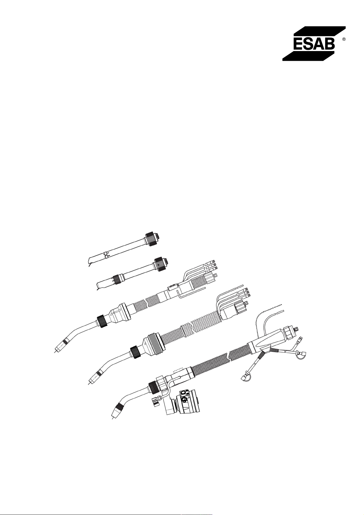
I sistemi di torcia di saldatura RT sono stati sviluppati per la saldatura MIG/MAG
completamente automatica tramite robot di saldatura. I sistemi sono composti da una serie di
colli per torce Aristo RT progettati per l'uso robotizzato, supporti torcia, gruppi cablaggi
ottimizzati per l'uso robotizzato e meccanismi di disattivazione di sicurezza atti a proteggere
il sistema contro i danni in caso di collisione.
Il sistema di saldatura RT standard assicura la protezione contro le collisioni mediante
l'impiego dell'RT KS-2, un dispositivo di disattivazione di sicurezza a molla meccanico. In via
facoltativa, questo può essere sostituito dall'RT FL-2 per sfruttare la funzione di rilevamento
delle collisioni del sistema di controllo del robot. Il sistema di saldatura RT standard può
essere utilizzato con una vasta gamma di gruppi cablaggi.
I supporti torcia RT KSC-2 e RT FLC-2, con gruppo cablaggi Infiniturn o Helix, sono destinati
all'uso con sistemi di saldatura robotizzati a polso cavo progettati per applicazioni di
saldatura avanzate. Il meccanismo di disattivazione di sicurezza presente nel supporto torcia
RT KSC-2 consente un'ampia deformazione elastica della torcia in caso di collisione. I gruppi
cablaggi Infiniturn e Helix sono semplici da installare e forniscono un sistema estremamente
affidabile con capacità di manovra precisa.
Unitamente alle già consolidate torce di saldatura robotizzate Aristo RT, questi componenti
creano un sistema estremamente affidabile e resistente che necessita di una manutenzione
minima.
Il manuale di istruzioni viene fornito alla consegna dei supporti torcia e dei gruppi cablaggi.
I numeri d'ordine, gli accessori disponibili, i ricambi e i componenti soggetti a usura
ESAB sono riportati nell'elenco dei ricambi.
0463 373 101
- 11 -
© ESAB AB 2018

3 INTRODUZIONE
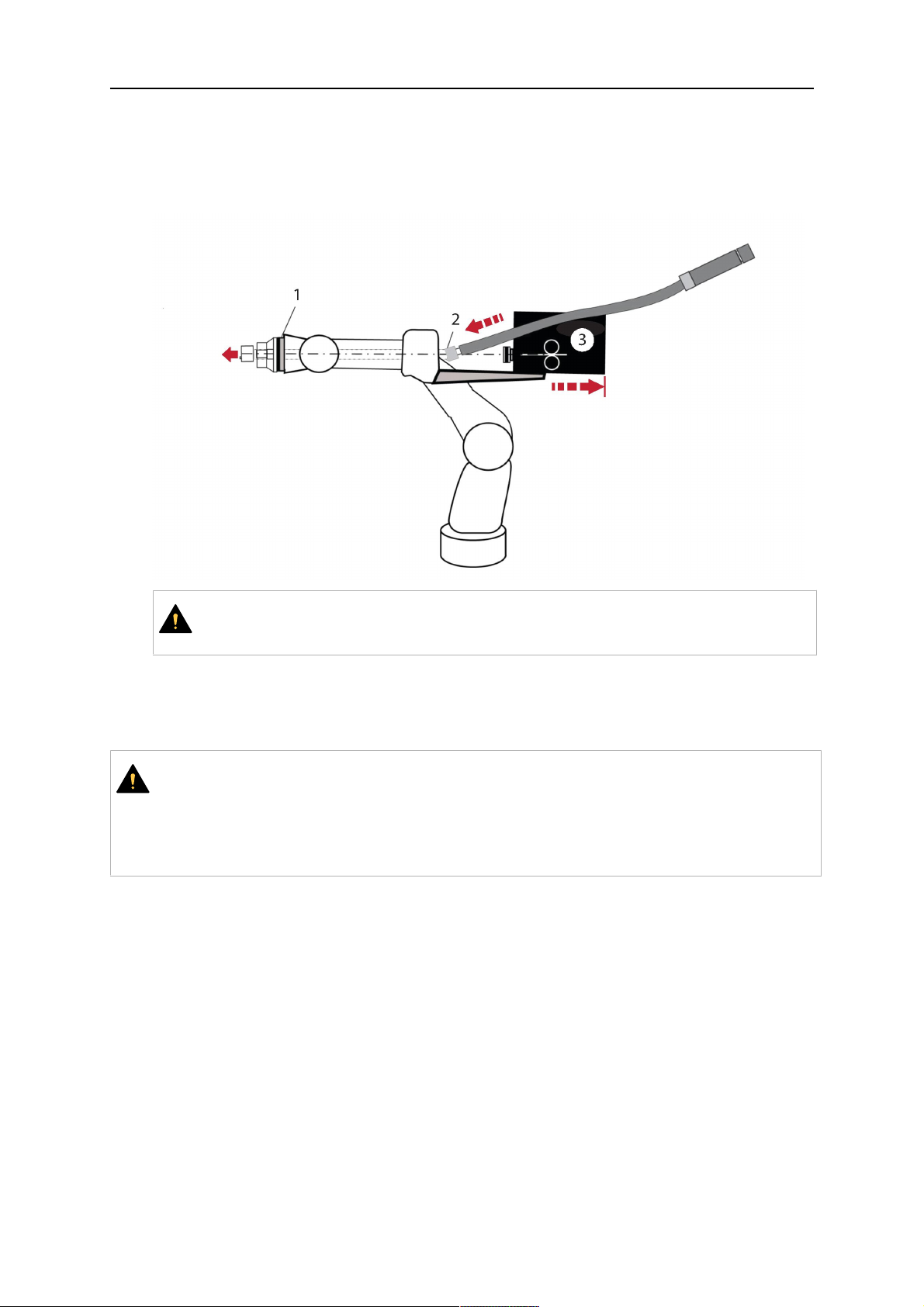
3.1 Panoramica dei sistemi di torcia di saldatura
Sistema RT standard
Per una descrizione dettagliata, fare
riferimento alla sezione corrispondente nel
capitolo CARATTERISTICHE TECNICHE:
1. Collo torcia
Vedere "Torcia di saldatura".
2. Gruppo cablaggi
Vedere "Gruppi cablaggi per
sistema RT standard".
3. Supporto torcia
Vedere "Supporti torcia per sistema
RT standard".
4. Meccanismo di disattivazione di
sicurezza RT KS-2
Vedere "Meccanismo di
disattivazione di sicurezza RT
KS-2".
5. Flangia intermedia RT FL-2
Vedere "Flangia intermedia RT
FL-2".
6. Flangia di adattamento (ove
richiesta)
Vedere "Flange di adattamento".
0463 373 101
- 12 -
© ESAB AB 2018

3 INTRODUZIONE
Sistema a polso cavo
Per una descrizione dettagliata, fare
riferimento alla sezione corrispondente nel
capitolo CARATTERISTICHE TECNICHE:
1. Collo torcia
Vedere "Torcia di saldatura".
2. Supporto torcia RT KSC-2
Vedere "Supporto torcia RT KSC-2
con meccanismo di disattivazione di
sicurezza".
3. Supporto torcia RT FLC-2
Vedere "Supporto torcia rigido RT
FLC-2".
4. Flangia di adattamento
Vedere "Flange di adattamento".
5. Gruppo cablaggi Helix o Infiniturn
Vedere "Gruppi cablaggi per sistemi
a polso cavo".
0463 373 101
- 13 -
© ESAB AB 2018

4 CARATTERISTICHE TECNICHE
4 CARATTERISTICHE TECNICHE
4.1 Collo torcia di saldatura
Scegliere il modello di torcia in base all'applicazione di saldatura. È necessario tenere
presente il ciclo di lavoro, la capacità, il metodo di raffreddamento e il diametro del filo
richiesti. In presenza di ulteriori requisiti, causati ad esempio da pezzi da lavorare
preriscaldati o da riflessi elevati di calore sugli angoli, è necessario prenderli in
considerazione scegliendo una torcia di saldatura con riserva di potenza nominale adeguata.
Le torce di saldatura RT sono destinate all'uso con generatori di saldatura a norma CE per i
processi di saldatura MIG (Metal Inert Gas) e MAG (Metal Active Gas), e di brasatura MIG
con fili tondi commerciali. Non utilizzare la torcia per altri processi.
Per la saldatura ad arco pulsato dell'acciaio o la saldatura di componenti in alluminio,
utilizzare la torcia raffreddata ad acqua RT 82W.
Vedere i modelli di torcia disponibili di seguito.
Modello di torcia
Metodo di
raffreddamento
Gas di protezione Valore nominale
RT42G Raffreddamento a gas CO
Raffreddamento a gas 300A / 100%
Raffreddamento a gas Miscela 350A / 60%
Raffreddamento a gas 250A / 100%
RT42W Raffreddamento ad
CO
acqua
Raffreddamento ad
acqua
Raffreddamento ad
Miscela 350A / 60%
acqua
Raffreddamento ad
acqua
RT52G Raffreddamento a gas CO
Raffreddamento a gas 300A / 100%
Raffreddamento a gas Miscela 350A / 60%
Raffreddamento a gas 250A / 100%
2
2
420A / 60%
420A / 60%
420A / 100%
350A / 100%
2
420A / 60%
RT52W Raffreddamento ad
CO
acqua
Raffreddamento ad
acqua
Raffreddamento ad
Miscela 400A / 60%
acqua
Raffreddamento ad
acqua
RT62G Raffreddamento a gas CO
Raffreddamento a gas 340A / 100%
Raffreddamento a gas Miscela 420A / 60%
Raffreddamento a gas 290A / 100%
0463 373 101
- 14 -
2
470A / 60%
470A / 100%
400A / 100%
2
500A / 60%
© ESAB AB 2018

4 CARATTERISTICHE TECNICHE
Modello di torcia
Metodo di
raffreddamento
RT62W Raffreddamento ad
Gas di protezione Valore nominale
CO
acqua
Raffreddamento ad
acqua
Raffreddamento ad
Miscela 450A / 60%
acqua
Raffreddamento ad
acqua
RT72G Raffreddamento a gas CO
Raffreddamento a gas 320A / 100%
Raffreddamento a gas Miscela 400A / 60%
Raffreddamento a gas 270A / 100%
RT72W Raffreddamento ad
CO
acqua
Raffreddamento ad
acqua
Raffreddamento ad
Miscela 480A / 60%
acqua
2
530A / 60%
530A / 100%
450A / 100%
2
2
480 A / 60%
480A / 60%
430A / 100%
Raffreddamento ad
430A / 100%
acqua
RT82W Raffreddamento ad
CO
2
600A / 60%
acqua
Raffreddamento ad
600A / 100%
acqua
Raffreddamento ad
Miscela 550A / 60%
acqua
Raffreddamento ad
550A / 100%
acqua
I valori relativi alla potenza nominale e al ciclo di lavoro della torcia sono validi per un ciclo di
10 minuti.
Le caratteristiche tecniche sono valide per un'applicazione standardizzata in cui si impiegano
ricambi/componenti soggetti a usura standard. La potenza nominale della torcia è ridotta
quando si utilizza la modalità di trasferimento del metallo ad arco pulsato.
Intervalli di temperatura Stoccaggio: -15–50 °C (5–122 °F)
Funzionamento: 5–40 °C (41–104 °F)
Gas di erogazione Max. 10 bar, flessibile del gas separato
Peso complessivo (collo torcia, meccanismo
di disattivazione di sicurezza, supporto torcia
e gruppo cablaggi da 1 m)
0463 373 101
Circa 5 kg
- 15 -
© ESAB AB 2018
4 CARATTERISTICHE TECNICHE
4.2 Tensione nominale
Amperaggio / tensione max. consentita
Sistema di torcia di saldatura completo 141 V (valore di picco per la saldatura)
Circuito di controllo del meccanismo di
disattivazione di sicurezza RT KS-2
24 V / 1 A
48 V / 0,1 A
Pulsante RT KS-2
Circuito di controllo del meccanismo di
48 V
disattivazione di sicurezza RT KSC-2
Usando la funzione di rilevamento dell'ugello
con un gruppo cablaggi standard
50 V / 5 A
(Carico max. consentito per 1 minuto alla
corrente nominale)
Usando la funzione di rilevamento dell'ugello
con un gruppo cablaggi Helix o Infiniturn
50 V / 5 A
(Carico max. consentito per 1 minuto alla
corrente nominale)
Le potenze nominali indicate si riferiscono a condizioni d'uso standardizzate.
Per le potenze nominali dei gruppi cablaggi, vedere la sezione "Gruppi cablaggi".
4.2.1 Limiti del circuito di raffreddamento
Validi solo per le versioni con raffreddamento ad acqua.
Portata dell'acqua min.: 1,0 l/min (1,1 quarti/min)
Pressione acqua min.: 2,5 bar (36,3 PSI)
Pressione acqua max.: 3,5 bar (50,8 PSI)
Temperatura in ingresso: Max. 40 °C (104 °F)
Temperatura di ritorno: Max. 60 °C (140 °F)
Capacità di raffreddamento: Min. 1000 W, a seconda dell'applicazione
AVVISO!
Temperature di ritorno superiori a 60 °C (140 °F) potrebbero danneggiare o
distruggere il gruppo cablaggi.
4.3 Supporto torcia
Il tipo di supporto torcia richiesto dipende dal design del sistema di torcia di saldatura RT e
dalla scelta dei dispositivi di disattivazione di sicurezza; vedere la sezione "Panoramica dei
sistemi di torcia di saldatura".
Componente Peso approssimativo
Supporto torcia (per il sistema standard) 0,43 kg
Meccanismo di disattivazione di sicurezza RT
KS-2 (per il sistema standard)
Flangia intermedia RT FL-2 (per il sistema
standard)
0,85 kg
0,35 kg
Supporto torcia RT KSC-2 (per il sistema a
polso cavo)
0463 373 101
1,90 kg
- 16 -
© ESAB AB 2018

4 CARATTERISTICHE TECNICHE
Supporto torcia rigido RT FLC-2 (per il
1,22 kg
sistema a polso cavo)
Torcia di saldatura per robot 0,66 kg
4.3.1 Supporti torcia per il sistema RT standard
Nei sistemi RT standard il supporto torcia è montato sul meccanismo di disattivazione di
sicurezza RT KS-2 (o, in alternativa, sulla flangia intermedia RT FL-2), fissando il gruppo
cablaggi e il collo torcia collegato.
Scegliere il supporto torcia in base al tipo di torcia e alla relativa geometria. È possibile
utilizzare diversi tipi di supporti. Vedere l'elenco dei ricambi per i supporti torcia disponibili per
il sistema RT standard.
Supporto torcia per robot con braccio standard
4.3.1.1 Meccanismo di disattivazione di sicurezza RT KS-2
Il meccanismo di disattivazione di sicurezza RT KS-2 è un dispositivo a molla che protegge
il robot e il sistema di torcia in caso di collisione.
NOTA:
Non smontare il dispositivo RT KS-2.
0463 373 101
- 17 -
© ESAB AB 2018

4 CARATTERISTICHE TECNICHE
4.3.1.2 Flangia intermedia RT FL-2
La flangia intermedia rigida RT FL-2 può essere usata al posto del dispositivo RT KS-2 se il
robot è dotato di sistema di rilevamento collisioni elettronico.
4.3.2 Supporti torcia per il sistema a polso cavo
Nel sistema a polso cavo, i colli torcia di saldatura Aristo RT sono collegati al supporto torcia
KSC-2 o FLC-2.
Il supporto torcia RT KSC-2 consente la deformazione elastica della torcia in caso di
collisione. Contemporaneamente, si apre un contatto elettrico che segnala al sistema di
controllo del robot di fermarsi. Una volta resettata l'anomalia, la geometria iniziale e il TCP
(Tool Center Point) della torcia verranno raggiunti con elevata precisione. Il sistema funziona
in modo esclusivamente meccanico ed è caricato a molla.
Il supporto torcia RT FLC-2 non è dotato di una funzione di disattivazione di sicurezza
incorporata.
Nei sistemi a polso cavo si consiglia di utilizzare il dispositivo RTKSC-2 G/W (o, in
alternativa, RTFLC-2 G/W). È possibile utilizzare il supporto torcia sia con le torce
raffreddate a gas, sia con le torce raffreddate ad acqua della serie Aristo RT.
RTKSC-2 G/W RTFLC-2 G/W
Principio di funzionamento
del meccanismo di
Meccanico Non applicabile (supporto
rigido)
disattivazione di sicurezza
Forza di rilascio assiale (Fz) 650 N Non applicabile (supporto
rigido)
0463 373 101
- 18 -
© ESAB AB 2018
4 CARATTERISTICHE TECNICHE
Coppia di rilascio sull'asse
trasversale (Mx)
24 Nm Non applicabile (supporto
rigido)
Reset dopo il rilascio Automatico Non applicabile (supporto
rigido)
Ripetibilità Laterale ± 0,1 mm al TCP di
una torcia Aristo RT standard
Non applicabile (supporto
rigido)
Deformazione max. Circa ± 8° Non applicabile (supporto
rigido)
Interruttore di sicurezza Normalmente chiuso
Carico elettrico max. 48 V / 1
Non applicabile (supporto
rigido)
A
Circuito di controllo elettrico
per la funzione di rilevamento
dell'ugello
Potenza nominale:
• Per i gruppi di cablaggi
Helix: max. 50 V CC / 5
A, max. 1 minuto
Dopo il rilevamento del
contatto, disinserire
rapidamente la tensione
di rilevamento.
• Nei gruppi cablaggi
Infiniturn la funzione di
rilevamento dell'ugello
Potenza nominale:
• Per i gruppi di cablaggi
Helix: max. 50 V CC / 5
A, max. 1 minuto
• Per i gruppi di cablaggi
Infiniturn: max. 50 V CC
/ 1 A, max. 1 minuto
Dopo il rilevamento del
contatto, disinserire
rapidamente la tensione di
rilevamento.
ha una funzionalità
limitata. Contattare
ESAB per un'indagine
dettagliata delle
soluzioni possibili per la
propria applicazione.
Tensione nominale Tensione massima consentita
per il circuito di controllo del
meccanismo di disattivazione
di sicurezza: 48 V.
0463 373 101
- 19 -
© ESAB AB 2018
4 CARATTERISTICHE TECNICHE
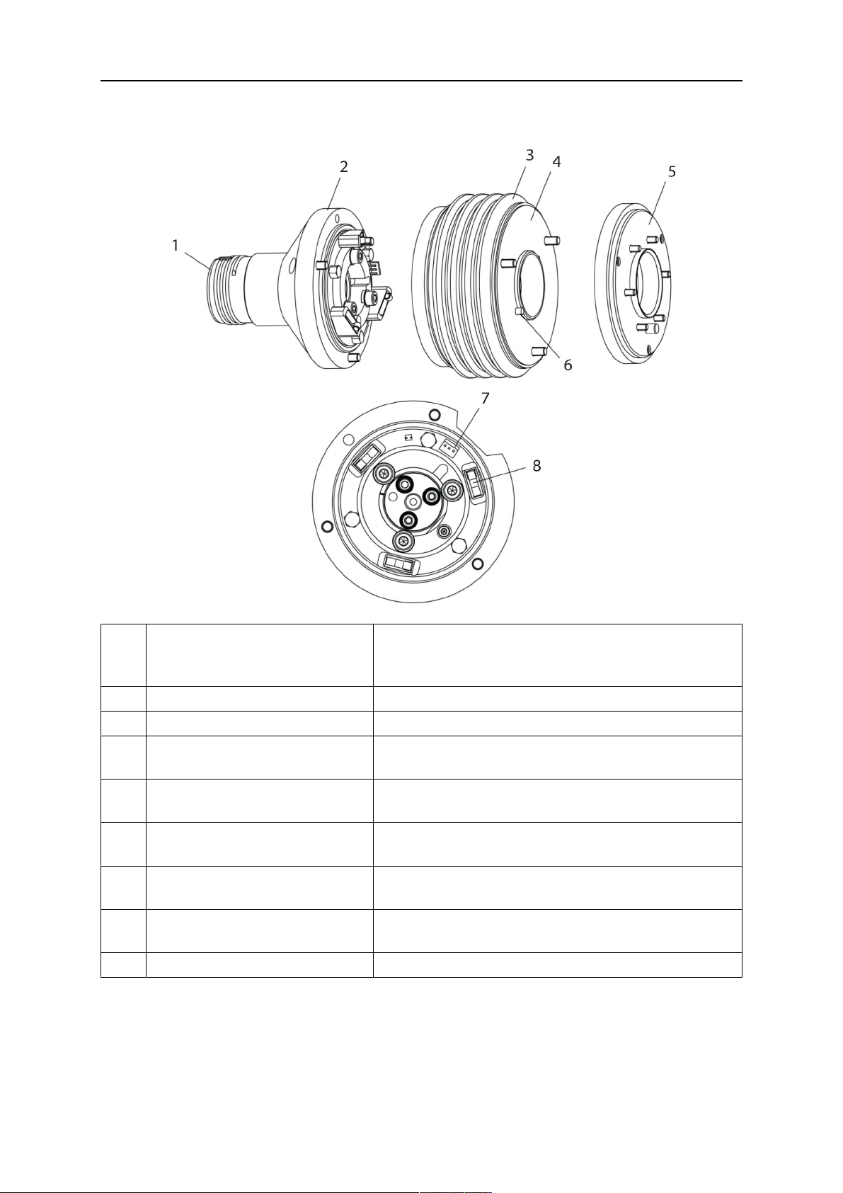
4.3.2.1 Supporto torcia RT KSC-2 G/W con meccanismo di disattivazione di sicurezza
Com
Descrizione Funzione
pone
nte
1 Supporto per collo torcia Interfaccia della torcia Aristo RT
2 Coperchio RT KSC-2 Gruppo con interfacce torcia e cavo
3 Guaina in gomma Protezione per il meccanismo di disattivazione di
sicurezza
4 Corpo principale RT KSC-2 Consente la deformazione meccanica durante una
collisione
5 Flangia di adattamento Interfaccia di isolamento con il polso del robot (deve
essere adeguata allo specifico robot)
6 Perno di riferimento Per l'allineamento preciso rispetto alla flangia di
adattamento
7 Connettore per cavo di
comando
Collegamento elettrico per il segnale di collisione e
la funzione di rilevamento dell'ugello
8 Micro interruttore Sensore di rilevamento collisioni
0463 373 101
- 20 -
© ESAB AB 2018
4 CARATTERISTICHE TECNICHE
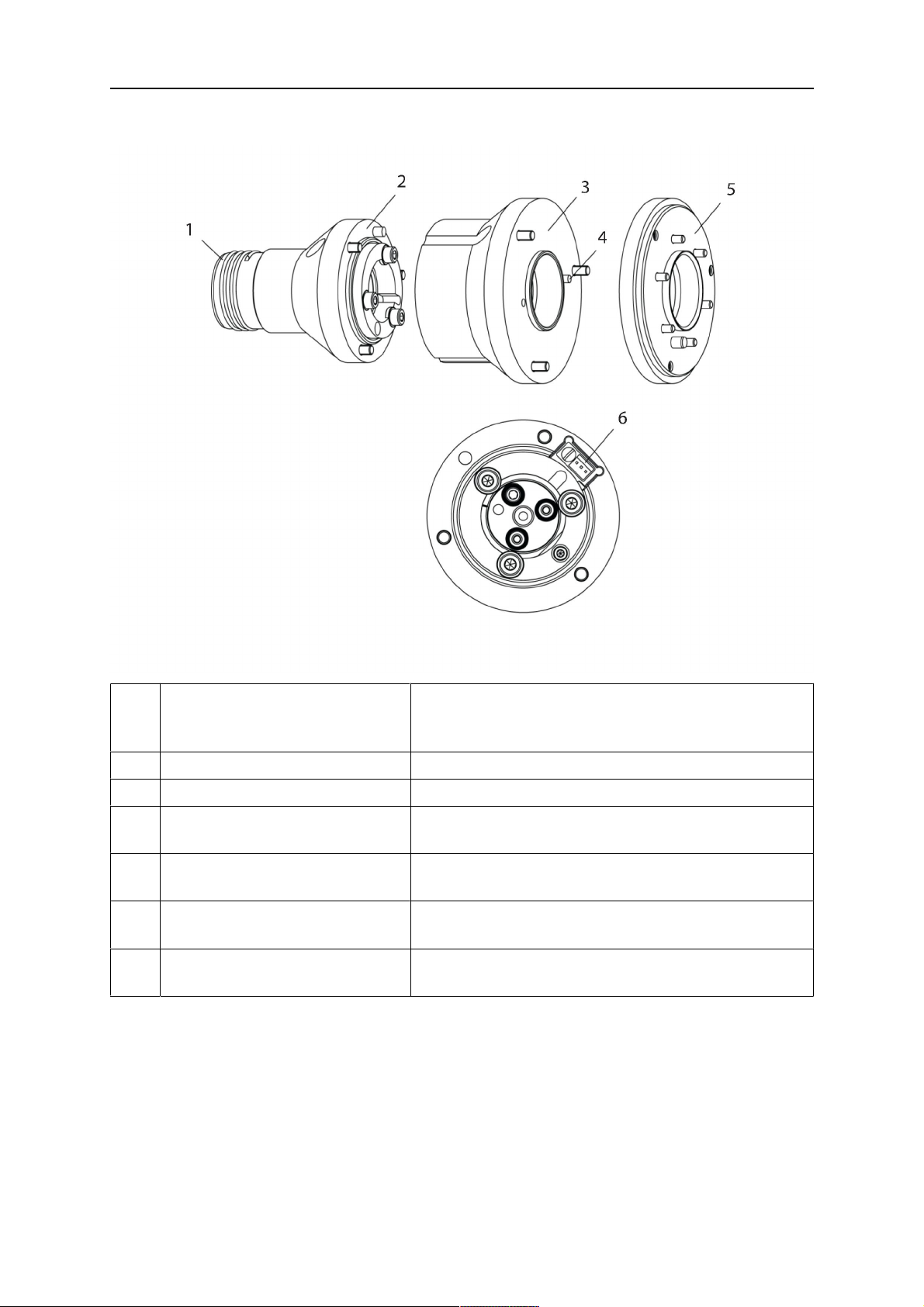
4.3.2.2 Supporto torcia rigido RTFLC-2 G/W
Com
Descrizione Funzione
pone
nte
1 Supporto per collo torcia Interfaccia della torcia Aristo RT
2 Coperchio RT FLC-2 Gruppo con interfacce torcia e cavo
3 Corpo principale RT FLC-2 Consente la deformazione meccanica durante una
collisione
4 Perno di riferimento Per l'allineamento preciso rispetto alla flangia di
adattamento
5 Flangia di adattamento Interfaccia di isolamento con il polso del robot (deve
essere adeguata allo specifico robot)
6 Connettore per cavo di
comando (a 3 poli)
Collegamento elettrico per la funzione di
rilevamento dell'ugello (ove applicabile)
4.4 Flange di adattamento
Scegliere la flangia di adattamento richiesta per l'installazione sul braccio del robot in base al
tipo di robot. Sono disponibili flange di adattamento per tutti i sistemi standard e a polso cavo
idonei; vedere l'elenco dei ricambi.
4.5 Gruppi cablaggi
Il collegamento al trainafilo avviene mediante il gruppo cablaggi; le versioni disponibili
dipendono principalmente dal design del sistema e dal mezzo di raffreddamento (gas o
acqua). Vedere l'elenco dei ricambi.
0463 373 101
- 21 -
© ESAB AB 2018
4 CARATTERISTICHE TECNICHE
Le potenze nominali sono valide per cavi di lunghezza compresa tra 1 e 5 m.
Gruppo cablaggi
Infiniturn Helix
standard
Potenza nominale
(ciclo di 10 min.)
Raffreddamento a gas
(miscela di gas)
Potenza nominale
(ciclo di 10 min.)
Max. 500 A / 60% del
ciclo di lavoro
Max. 350 A / 100%
del ciclo di lavoro
Max. 600 A / 100%
del ciclo di lavoro
Max. 400 A / 60% del
ciclo di lavoro
Max. 320 A / 100%
del ciclo di lavoro
Max. 550 A / 100%
del ciclo di lavoro
Max. 400 A / 60% del
ciclo di lavoro
Max. 320 A / 100%
del ciclo di lavoro
Max. 550 A / 100%
del ciclo di lavoro
Raffreddamento ad
acqua
Campo di rotazione Ruotabilità limitata Ruotabile all'infinito ± 270° dalla posizione
neutra
Peso
Raffreddamento a gas
Peso
Raffreddamento ad
Lunghezza di 1,2 m:
2,35 kg
Lunghezza di 1,2 m:
2,35 kg
Lunghezza di 1,0 m:
2,0 kg
Lunghezza di 1,0 m:
2,0 kg
Lunghezza di 1,0 m:
2,0 kg
Lunghezza di 1,0 m:
2,0 kg
acqua
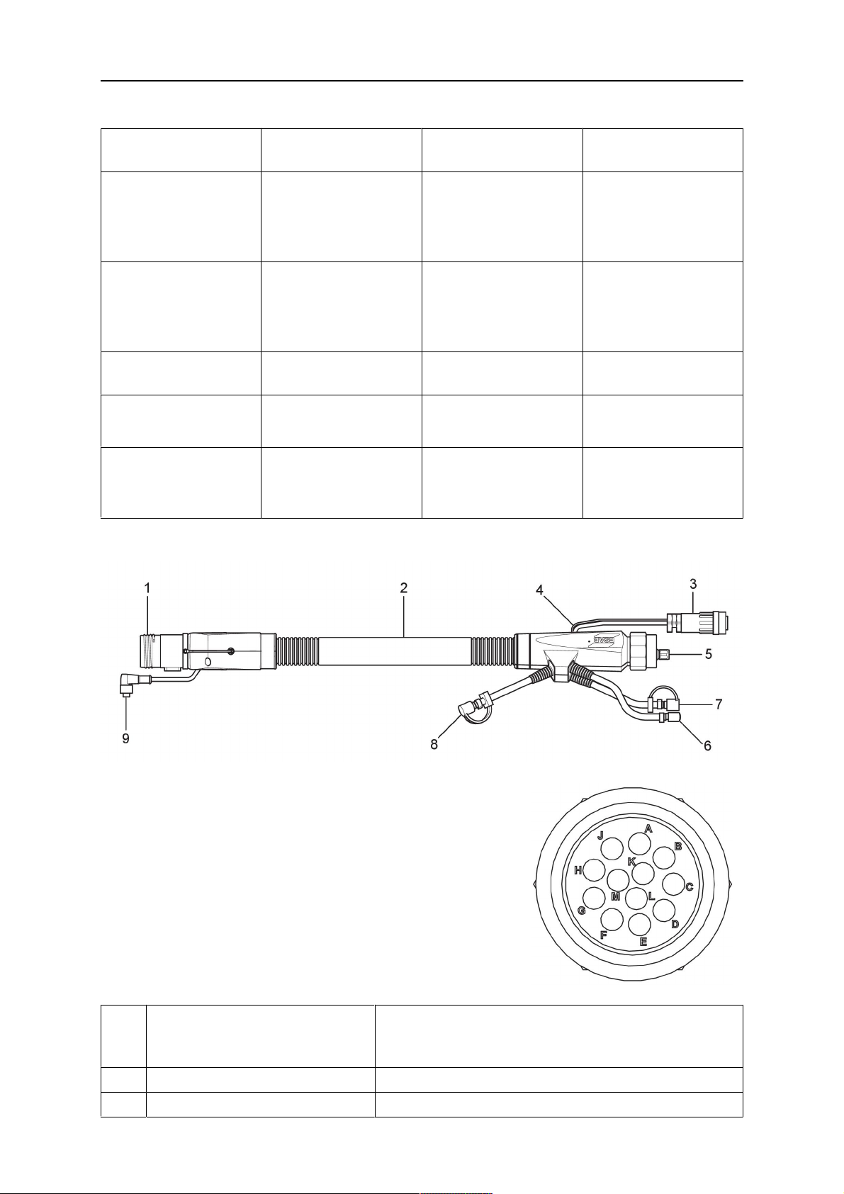
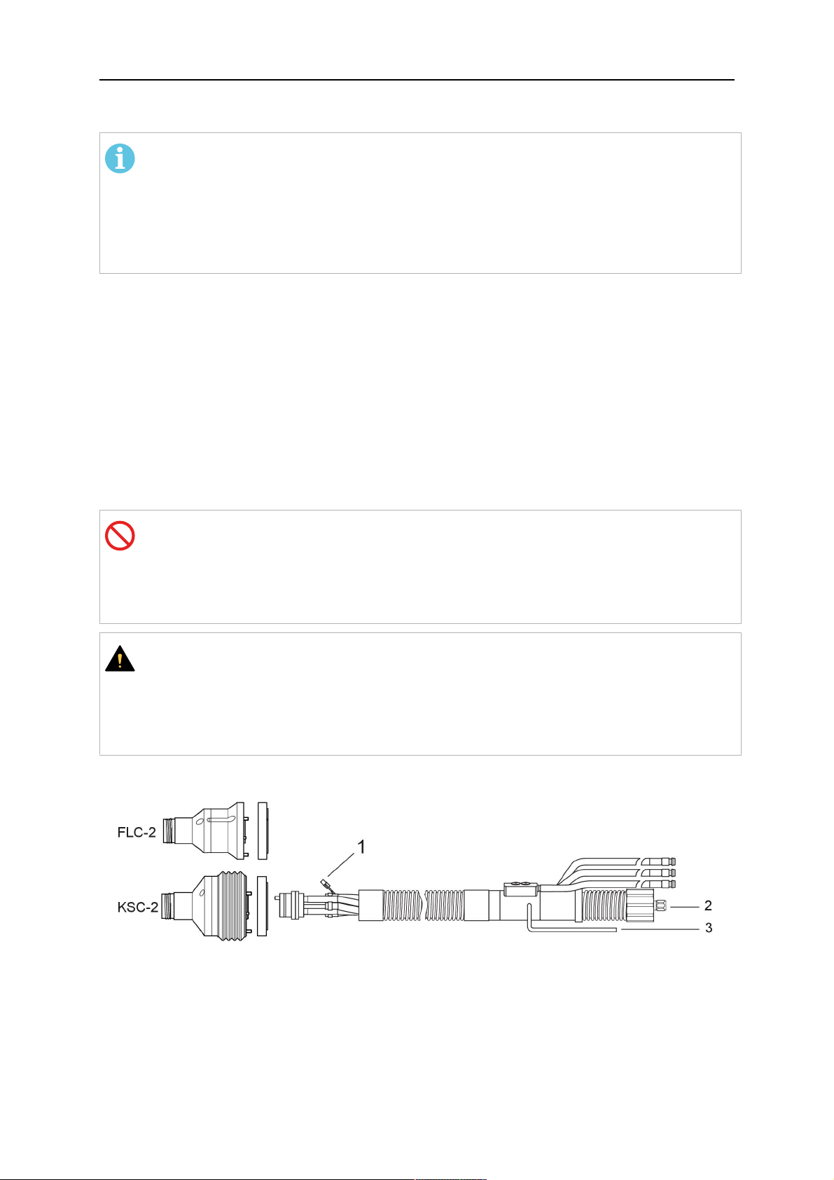
4.5.1 Gruppi cablaggi per sistema RT standard
Pin dei connettori Burndy
A. Ugello del gas Touch
sense
C. Sensore di collisione
F. 0V
G. Tensione motore +
H. Tensione motore -
D. Sensore di collisione
E. Avanzamento
Com
Descrizione Funzione
pone
nte
1 Flangia di supporto collo Interfaccia della torcia
2 Coperchio di protezione Protegge il gruppo cablaggi dai danni
0463 373 101
- 22 -
© ESAB AB 2018
4 CARATTERISTICHE TECNICHE
Com
Descrizione Funzione
pone
nte
3 Connettore Burndy, a 12 poli Collegamento elettrico tra il meccanismo di
disattivazione di sicurezza e il trainafilo
4 Cavo di comando Per KS-2 (meccanismo di disattivazione di sicurezza
e pulsante)
5 Connettore europeo Collegamento del trainafilo
6 Flessibile di erogazione
(cappuccio nero)
7 Ingresso acqua (cappuccio blu)
8 Ritorno di acqua (cappuccio
Per la pulizia con aria compressa della torcia dopo
un ciclo di pulizia
Ingresso acqua per il raffreddamento della torcia
Ritorno di acqua riscaldata dalla torcia
1)
1)
rosso)
9 Spina del cavo di comando per
il meccanismo di disattivazione
di sicurezza
1)
Solo i sistemi di torcia raffreddati ad acqua
Collegamento elettrico con l'RT KS-2 per il segnale
di disattivazione di sicurezza e la funzione di
rilevamento dell'ugello
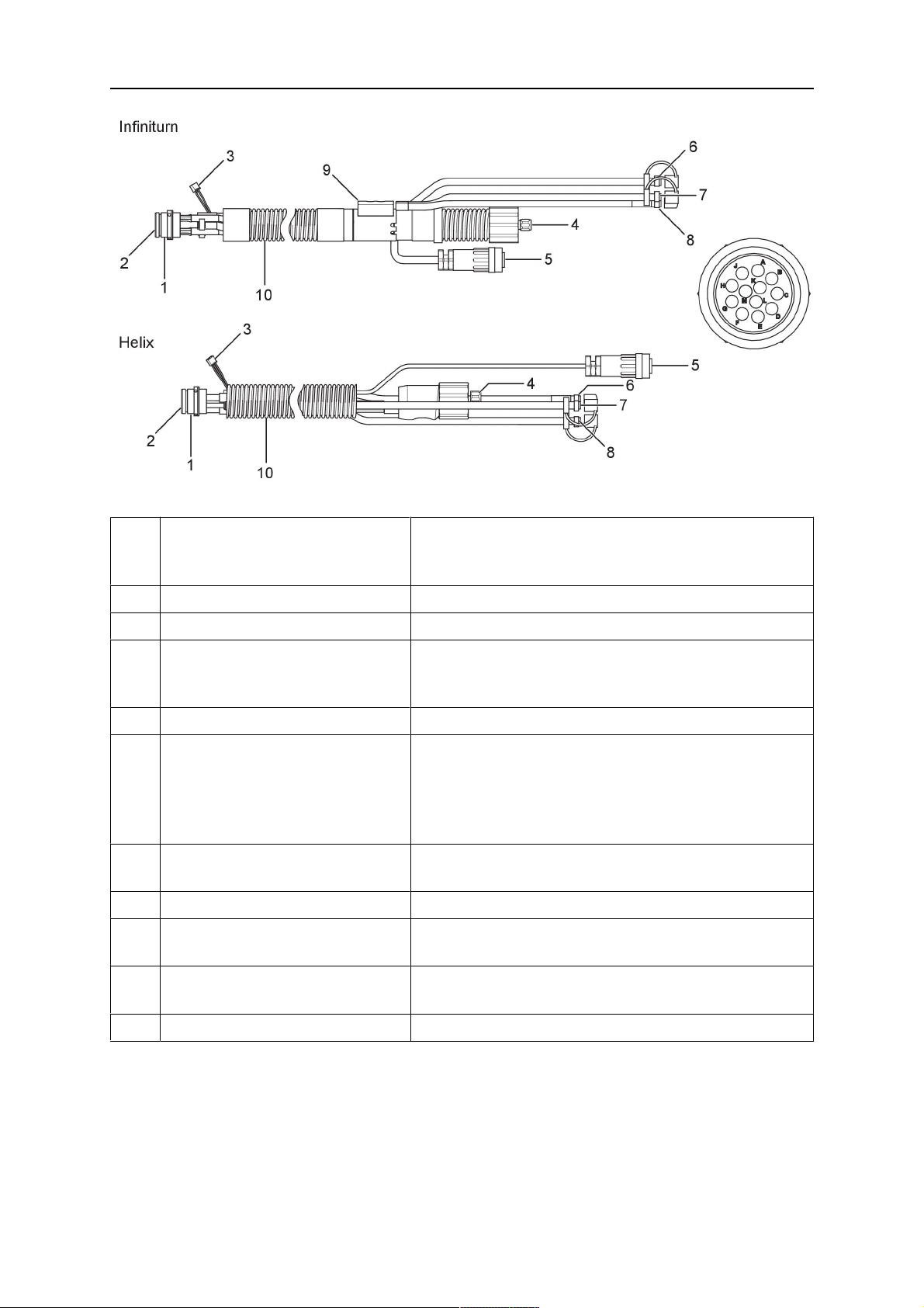
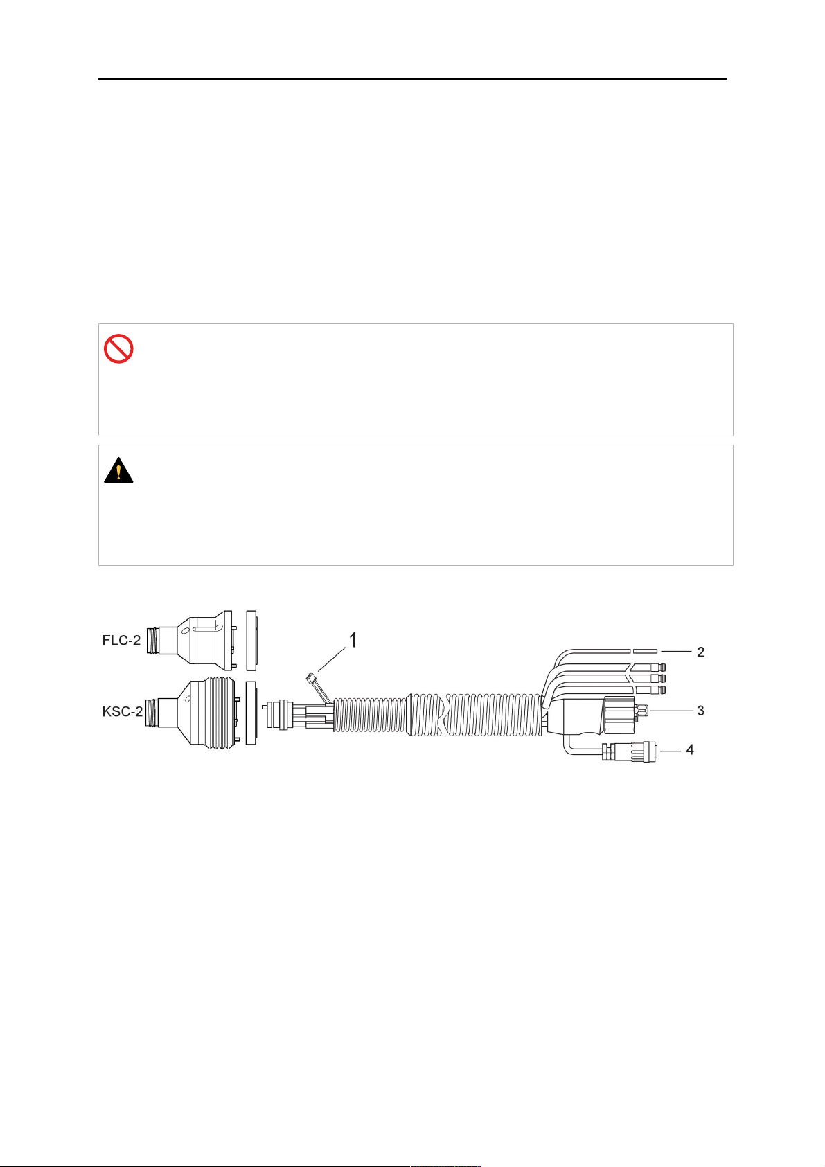
4.5.2 Gruppi cablaggi per sistemi a polso cavo
Il gruppo cablaggi Infiniturn consente la rotazione continua della torcia in entrambe le
direzioni. Allo stesso tempo, vengono trasferiti il liquido di raffreddamento, il gas di
protezione, l'aria di erogazione, la corrente di saldatura e il segnale del meccanismo di
disattivazione di sicurezza.
Il gruppo cablaggi Helix è stato progettato per un campo di rotazione di ±270° dalla posizione
neutra. Può essere utilizzato per operazioni di saldatura che non richiedono una rotazione
continua.
I gruppi cablaggi Infiniturn sono disponibili nelle versioni con raffreddamento a gas e ad
acqua. Il gruppi cablaggi Helix possono essere usati sia per le applicazioni con
raffreddamento a gas, sia per quelle con raffreddamento ad acqua.
NOTA:
Non collegare un gruppo cablaggi Helix azionato mediante un collo torcia
raffreddato a gas a un sistema di raffreddamento ad acqua.
0463 373 101
- 23 -
© ESAB AB 2018
4 CARATTERISTICHE TECNICHE
Com
Descrizione Funzione
pone
nte
1 Flangia Interfaccia supporto torcia RT KSC-2 / RT FLC-2
2 Perno di riferimento Assicura il corretto orientamento del raccordo
3 Spina del cavo di comando Collegamento elettrico all'RT KSC-2 per il segnale
di disattivazione di sicurezza e la funzione di
rilevamento dell'ugello (ove applicabile)
4 Connettore europeo Collegamento del trainafilo
5 Cavo di comando Collegamento elettrico per il segnale di
disattivazione di sicurezza (proveniente dall'RT
KSC-2) e la funzione di rilevamento dell'ugello (la
funzione è di serie sul gruppo cablaggi Helix ma non
sull'Infiniturn)
6 Ritorno di acqua (cappuccio
Ritorno di acqua riscaldata dalla torcia
rosso)
7 Ingresso acqua (cappuccio blu) Ingresso acqua per il raffreddamento della torcia
8 Flessibile di erogazione
(cappuccio nero)
Per la pulizia con aria compressa della torcia dopo
le operazioni di saldatura
9 Raccordo liquidi Raccordo a rotazione continua con trasferimento dei
liquidi
10 Coperchio di protezione Protegge il gruppo cablaggi dai danni
0463 373 101
- 24 -
© ESAB AB 2018
5 INSTALLATION
5 INSTALLATION
ATTENZIONE!
For your own safety, make sure that the robot is either in standby or power-less
state before doing maintenance work in the moving radius of the robot.
Follow the assembly instructions exactly. Pay attention during assembly that the cables are
not damaged. Damaged cables can lead to a short circuit, which may damage the electronics
of the robot or the welding torch.
Use only original ESAB components that have been specially developed for this purpose.
Only then the correct functioning of the whole welding torch system can be guaranteed.
5.1 RTKS-2 standard arm installation
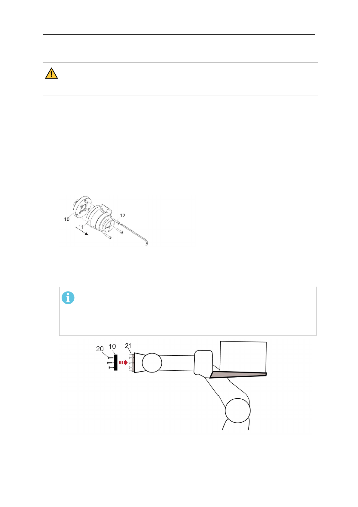
5.1.1 RTKS-2 safety-off mechanism
1. Dismount the insulation flange (10) from the RTKS-2 (11) by removing the screws
(12).
2. Position the insulation flange (10) with the index pin on the robot arm and fix it with the
screws (20) included.
The insulation flange (10) is directly compatible with robots with tool flange according
to DIN ISO 9409-1-A40 (diameter 40mm, 4×M6). If the insulation flange (10) does
not fit, use an adapter flange (21).
NOTA:
Ensure that the index pin is located correctly. The maximum torque of 1.2Nm
(10.5in.lb) must be observed for the fastening of the adapter flange screws.
Prevent self-loosening of the screws by using suitable thread locking
measures.
3. Mount the RTKS-2 the back on the insulation flange (10).
0463 373 101
- 25 -
© ESAB AB 2018

5 INSTALLATION
4. Position the mount on the RTKS-2 and carefully insert the cylindrical pins (14) into the
holes provided. Take the position of the torch into account. Two mounting positions
may be potentially possible.
5. Screw the mount evenly using the enclosed cylinder screws with hexagon socket (12).
NOTA:
The maximum tightening torque for the cylinder screw (5) is 6Nm (53in.lb)
and the property class category is 8.8.
12 - Cylinder screw with hexagon socket
M6DIN912 (length of the screw depending
on the torch mount)
14 - Cylindrical pins Ø4×20
5.1.1.1 Torch installation with adjustable mount
Torch mounts with a central clamping assembly can only be fastened on the journal of the
mounting flange. For this, the mounting flange must be fastened first.
1. If applicable, carefully press the cylindrical pins (1) into the corresponding holes in the
mounting flange. The pins should protrude by approximately 5 mm (0.2 in.).
2. Position the mount on the safety-off mechanism RTKS-2 and carefully insert the
cylindrical pins (1) into the holes provided. In doing so, take the later position of the
torch into account. Two mounting positions may be potentially possible.
3. Then screw down the mounting flange evenly using the enclosed cylinder screws with
hexagon socket (2).
NOTA:
The maximum tightening torque for the cylinder screw (2) is 7.1 Nm (62.8
in.lb) and the property class category is 8.8.
0463 373 101
- 26 -
© ESAB AB 2018

5 INSTALLATION
4. Unscrew the axial cylinder screw with hexagon socket (4) out of the mounting flange
together with the washer (3).
1 - Cylindrical pins Ø4×14 3 - Washer Ø9 mm
2 - Cylinder screw with hexagon socket
M6×16
4 - Axial cylinder screw with hexagon
socket M8×16
5. Place the torch mount (5) onto the journal (6) of the mounting flange, paying attention
while doing so to the exact alignment of the feather key (7) and the corresponding
groove (7a).
6. Insert the clamping mandrel (8) into the lateral hole (see illustration) and position it so
that the mating surfaces (9a) of the clamping mandrel rest on the mating surface (9) of
the journal.
0463 373 101
- 27 -
© ESAB AB 2018

5 INSTALLATION
7. Fix the clamping mandrel from the opposite side using the M6 cylinder screw with
hexagon socket (10) and the Ø22 mm washer (11).
8. Screw the axial cylinder screw (4) with the Ø9 mm washer (3) into the mounting flange
and tighten firmly.
3 - Washer Ø9 mm 8 - Clamping mandrel
4 - Axial cylinder screw with hexagon
9 - Mating surface of mounting flange
socket M8×16
5 - Torch mount 9a - Mating surfaces of clamping mandrel
6 - Mounting flange journal 10 - Cylinder screw with hexagon socket
M6×30
7 Feather key 11 - Washer Ø22×6.4 mm
7a - Groove for feather key
5.1.2 Standard arm cable assembly for KS-2 and FL-2
The cable assembly must be aligned to the intended use in length and design. The type of
cooling for the torch and the cable assembly must be the same (either gas or water cooled
respectively). In order to prevent damage to the torch system and other components, it is
imperative to observe the following instructions.
0463 373 101
- 28 -
© ESAB AB 2018

5 INSTALLATION
AVVISO!
• Coordinate the length and design of the cable assembly to suit the range of
action of the robot.
• Do not bend, compress or overstretch the cable assembly.
• Fix the cable assembly such that is can be moved freely and cannot become
entangled.
• Any additional holding devices possibly installed, for example a balancer,
must not crush or bend the cable assembly.
• Extreme turning movements must be avoided in which the cable assembly
may become twisted.
• Chafing on the robot or other objects must be excluded.
1. Unscrew the cylinder screws (1) and lift off the top section (2) of the torch mount.
2. Insert the feather key (4) into the recess of the neck support flange (3) from below.
3. Align the neck support flange (3) including the feather key (4) to the groove (5) of the
torch mount and push into the groove right up to the stop of the flange.
4. Hold the cable assembly in this position and simultaneously place the top section (2)
back onto the torch mount. First screw both cylinder screws (1) loosely in to about the
same length, then tighten alternately. The top section (2) of the mount should have an
even gap to the bottom section.
The front part of the cable assembly is directly clamped into the torch mount (see
illustration below).
1 - Cylinder screws 4 - Feather key
2 - Torch mount top section 5 - Groove for feather key
3 - Neck support flange
5.1.3 RTKS-2 wire feeder connection
In order to be able to create the connection, the cable assembly must be mounted as
described in the "Installing the cable assembly" section and equipped following "Installing the
wire guide" section. Only then can the central and media connection take place. Proceed as
described below:
0463 373 101
- 29 -
© ESAB AB 2018

5 INSTALLATION
1. Connect the central connector of the cable assembly (2) to the wire feeder cabinet
socket. Tighten the central connector sleeve nut fingertight. Do not use tools.
1 - Burndy Connector 4 - Return of heated water (red cap)
2 - EURO central connector 5 - Return of heated water (red cap)
3 - Air blow-out 6 - Main Wire feeder
2. For water cooled systems. Connect the water hoses to the cooling circuit. The end of
the hose marked blue (4) is connected to the water outlet, and the end marked red (5)
is connected to the water return.
3. Connect the blow-out line (3) to the corresponding connection of the feeder.
4. Connect the Burndy Connector to the wire feeder. (1) to the feeder. See section
"Electrical connections".
NOTA:
All hoses and the control line must be installed so they can not bend or get
damaged!
5.1.4 RTKS-2 electrical connections
5.1.4.1 RTKS-2 safety-off mechanism connection
The switch for the safety-off functionality RTKS-2 is connected through the control cable,
see (3) in the illustration below. This connects to the RTKS-2 unit via the 4-pole plug (4) that
contains circuits for the push-button (6) and the safety-off signal (7).
If a collision is detected, the control circuit for the safety-off signal (7), which is normally
closed, will be interrupted.
Rating of the control circuit: max. 48 V / 1 A
0463 373 101
- 30 -
© ESAB AB 2018

5 INSTALLATION
2 - Burndy connector 5 - RTKS-2 connector for control cable plug
4 - Control cable plug
Pin dei connettori Burndy
A. Ugello del gas Touch
sense
C. Sensore di collisione
F. 0V
G. Tensione motore +
H. Tensione motore -
D. Sensore di collisione
E. Avanzamento
If the robot control provides a control circuit for nozzle sense functionality, the connection is
accomplished with a 1-wire connection.
Rating of the control circuit: max 50 V / 5 A.
PERICOLO!
If the nozzle sense function is not being used, the open end of the control cable on
the power source connection side must be properly isolated in order to avoid short
circuits. During certain problems on the torch head, the full welding potential may be
present on this cable.
AVVISO!
After detection of contact (gas nozzle on work piece), quickly reduce or cut off the
maximum current in the nozzle sense circuit in order to avoid overloading of the
system.
Allowed load max. 1 minute at the rated nominal current.
5.1.5 RTKS-2 Torch installation
Continue according to section "Torch installation".
0463 373 101
- 31 -
© ESAB AB 2018

5 INSTALLATION
5.2 RTFL-2 standard arm installation
5.2.1 RTFL-2 rigid mount
1. Position the RT FL-2 (2) with the index pin on the robot arm and fix it with the hexagon
socket screw included.
The FL-2 is directly compatible with robots with tool flange according to DIN ISO
9409-1-A40 (diameter 40mm, 4×M6). If the rigid mount does not fit, use an adapter
flange (3).
NOTA:
Ensure that the index pin is located correctly. The maximum torque of 1.2Nm
(10.5in.lb) must be observed for the fastening of the adapter flange screws.
Prevent self-loosening of the screws by using suitable thread locking
measures.
2. Install torch mount (1). Only torch mounts having a hole pattern equivalent with the
mounting surface may be attached. If necessary, carefully press the cylindrical pins (4)
into the corresponding holes in the bracket. The pins should protrude by
approximately 5mm (0.2in.). Position the torch mount on the RTFL-2 (2) and
carefully insert the cylindrical pins (4) into the holes provided. Take the position of the
torch into account. Two mounting positions may be potentially possible.
3. Screw the mount evenly using the enclosed cylinder screws with hexagon socket (5).
NOTA:
The maximum tightening torque for the cylinder screw (5) is 6Nm (53in.lb)
and the property class category is 8.8.
0463 373 101
- 32 -
© ESAB AB 2018

5 INSTALLATION
4 - Cylindrical pins Ø4×20
5 - Cylinder screw with hexagon socket M6
DIN 912 (length of the screw depending on
the torch mount)
Side view
Torch installation with adjustable mount
Torch mounts with a central clamping assembly can only be fastened on the journal of the
mounting flange. For this, the mounting flange must be fastened first.
1. If applicable, carefully press the cylindrical pins (1) into the corresponding holes in the
mounting flange. Avoid the formation of burrs. The pins should protrude by
approximately 5 mm (0.2 in.).
2. Position the mount on the RTFL-2 and carefully insert the cylindrical pins (1) into the
holes provided. In doing so, take the later position of the torch into account. Two
mounting positions may be potentially possible.
3. Then screw down the mounting flange evenly using the enclosed cylinder screws with
hexagon socket (2).
NOTA:
The maximum tightening torque for the cylinder screw (2) is 7.1 Nm (62.8
in.lb) and the property class category is 8.8.
4. Unscrew the axial cylinder screw with hexagon socket (4) out of the mounting flange
together with the washer (3).
1 - Cylindrical pins Ø4×14 3 - Washer Ø9 mm
2 - Cylinder screw with hexagon socket
M6×16
4 - Axial cylinder screw with hexagon
socket M8×16
5. Place the torch mount (5) onto the journal (6) of the mounting flange, paying attention
while doing so to the exact alignment of the feather key (7) and the corresponding
groove (7a).
0463 373 101
- 33 -
© ESAB AB 2018

5 INSTALLATION
6. Insert the clamping mandrel (8) into the lateral hole (see illustration) and position it so
that the mating surfaces (9a) of the clamping mandrel rest on the mating surface (9) of
the journal.
7. Fix the clamping mandrel from the opposite side using the M6 cylinder screw with
hexagon socket (10) and the Ø22 mm washer (11).
8. Screw the axial cylinder screw (4) with the Ø9 mm washer (3) into the mounting flange
and tighten firmly.
3 - Washer Ø9 mm 8 - Clamping mandrel
4 - Axial cylinder screw with hexagon
9 - Mating surface of mounting flange
socket M8×16
5 - Torch mount 9a - Mating surfaces of clamping mandrel
6 - Mounting flange journal 10 - Cylinder screw with hexagon socket
M6×30
7 - Feather key 11 - Washer Ø22×6.4 mm
7a - Groove for feather key
5.2.2 RTFL-2 torch installation
Continue according to section "Torch installation".
5.3 RTKSC-2 hollow wrist system installation
5.3.1 RTKSC-2 mount with safety off mechanism
AVVISO!
For hollow wrist systems make sure that the clear space around the robot is at least
Ø45 mm (1.8 in.) around the wrist and 50 mm (2.0 in.) near the wire feeder.
0463 373 101
- 34 -
© ESAB AB 2018
5 INSTALLATION
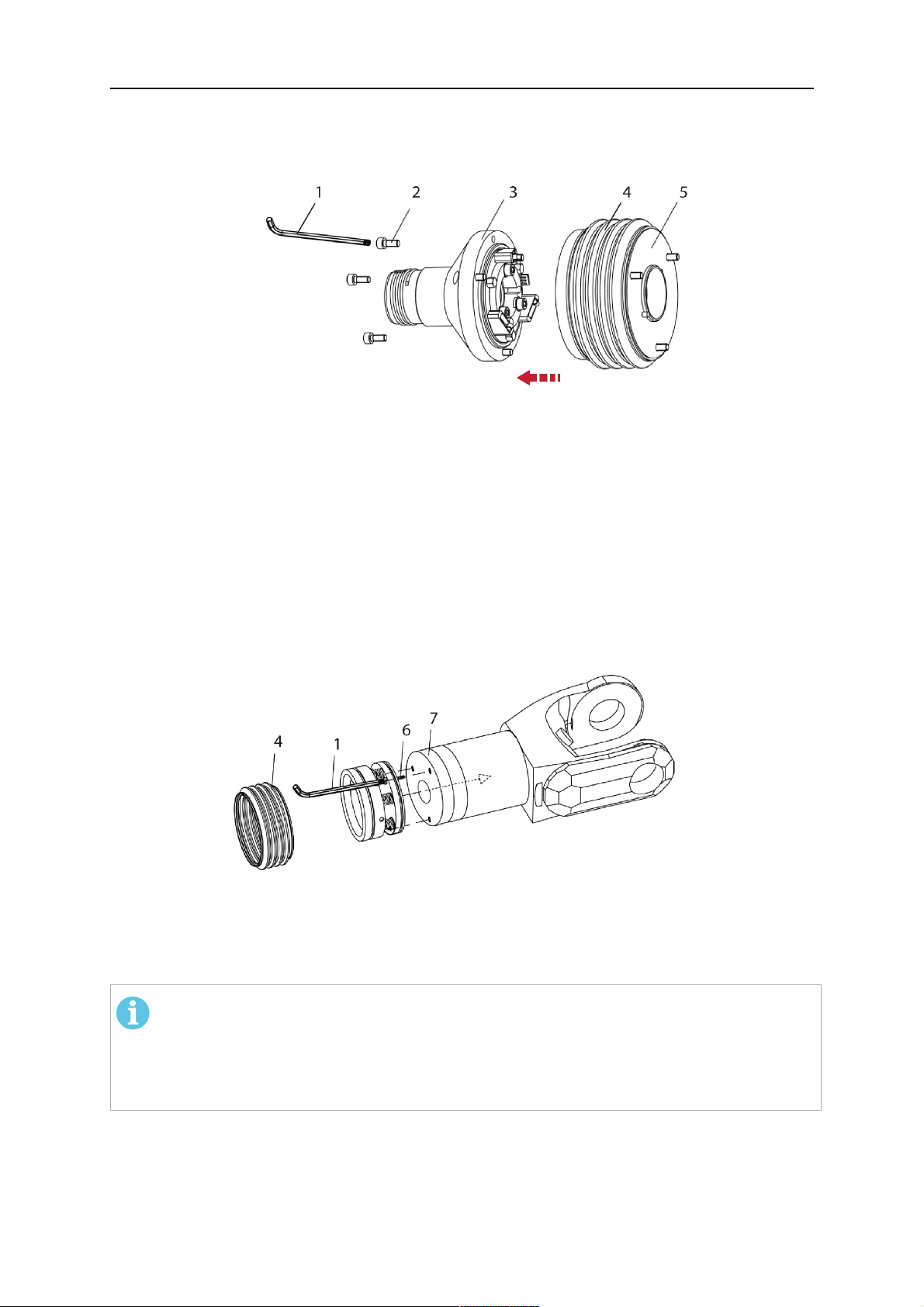
1. Remove the three screws (2) from the front cover (3) of the torch mount and carefully
pull the cover off the RTKSC-2 main body (5). Take care not to damage the micro
switches installed inside the assembly.
1 - Hexagon wrench 4 mm 4 - Rubber boot
2 - 3× M5×12 screws 5 - RT KSC-2 main body
3 - RT KSC-2 front cover
1. Pull off the rubber boot (4) from the RTKSC-2 main body (5) to the front.
2. Now position the RTKSC-2 main body (5) on the adapter flange (7) so that the index
pin is correctly seated. Attach with the screws (6) enclosed.
3. Reinstall the rubber boot (4) on the RTKSC-2 main body (5) and make sure it is
correctly located in the grooves on the front and back flange.
4. Istall the adapter flange (7) on the robot.
Fastening torque max. 2.2 Nm (19.5 in.lb).
1 - Hexagon wrench 4 mm 3 - 3× M5×12 hexagon socket screws
2 - Rubber boot 4 - Adapter flange
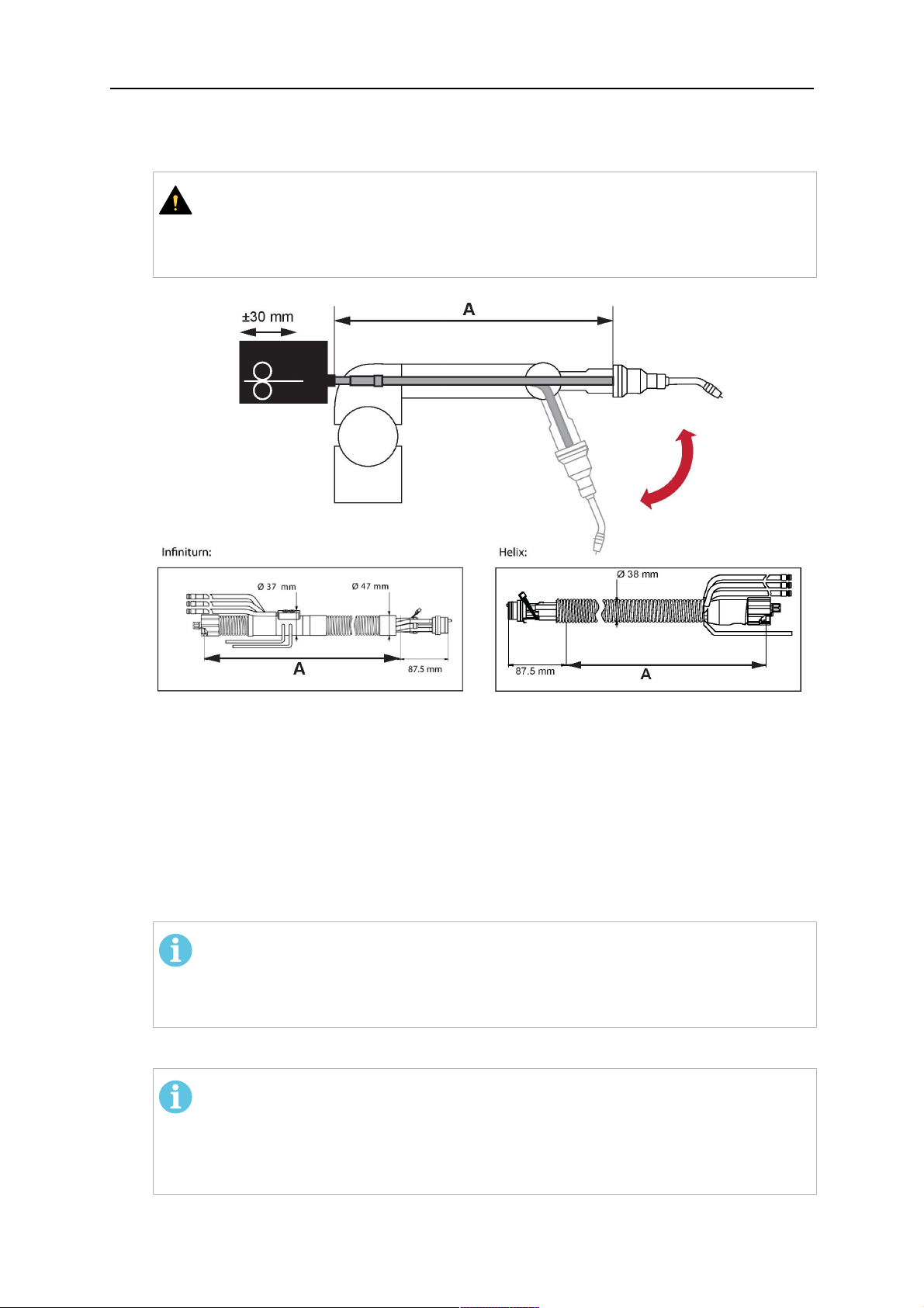
5.3.2 Mounting the cable assembly
NOTA:
In order to adjust the wire feeder position to the cable assembly length, it must be
mounted on an adjustable support with a possible movement of ±2-3cm (±1in.) to
the back and to the front. The length of the cable assembly must be determined
from the centred mounting position of the wire feeder.
1. Move the robot arm into a completely straight position, see illustration below. Make
sure that (1) axis 6 (rotation around the torch axis) is in 0° position.
2. Move the feeder (3) completely to the back in order to create space for inserting the
cable assembly. If it is not possible to move the feeder sufficiently, it should be
removed from the robot.
0463 373 101
- 35 -
© ESAB AB 2018
5 INSTALLATION
3. Insert the cable assembly with the coupling (2) first into the robot arm and feed it
through the robot wrist.
4. The feeder should only be installed again after the correct mounting position with
respect to the cable length has been determined. (See section "Installing the cable
assembly").
AVVISO!
Axis 6 must be in 0° position.
5.3.2.1 RTKSC-2 feeder cabinet connections
When installed for the first time, the position of the wire feeder cabinet must be adjusted to
the length of the cable assembly. First, the robot arm must be fully extended (straight).
AVVISO!
As long as the correct position of the feeder corresponding to the length of the cable
assembly has not been determined, be careful when moving the robot arm and
avoid overstretching the cable. It is helpful to loosen the positioning screws of the
feeder before moving the robot arm to allow the feeder to follow the cable assembly.
0463 373 101
- 36 -
© ESAB AB 2018
5 INSTALLATION
1. Loosen the sliding mechanism of the wire feeder and connect the cable assembly.
2. Now adjust the position of the wire feeder to suit the length of the Infiniturn or Helix
cable, as indicated with "A" in the illustration below.
AVVISO!
When adjusting the position of the feeder cabinet, make sure that the cable
assembly is not under stress when the robot arm is in stretched-out position.
It is normal for the cable assembly to sag slightly, it should never be taut.
3. Before securing the wire feeder in its permanent position, ensure that the Euro
connectors are tightly connected. Then turn the torch mount down and up again
(rotating on the axis 5), in order not to tighten the cable assembly too much against
the feeder (see illustration above). Once this is done, tighten the feeder in that
position.
4. For water cooled systems, connect the water lines to the cooling circuit. See section
"Cable assemblies for hollow wrist systems" in the TECHNICAL DATA chapter for
indications.
The hose with the blue rubber cap is for cooling water to the torch, the hose with the
red rubber cap returns the heated water. Make sure the hoses will not kink or get
otherwise blocked.
NOTA:
A Helix cable assembly used for a gas cooled system must not be connected
to a cooling circuit. As the water connections are not needed, they may be cut
off.
5. Connect the blow-out hose (black rubber cap) to the corresponding outlet of the wire
feeder.
NOTA:
If the blow-out function is not used, the blow-out hose must be sealed with the
rubber cap enclosed. With Infiniturn systems, the blow-out air must be
supplied to the corresponding connection hose, if it is not permitted to connect
blow-out air to the shield gas connection!
6. Install the necessary plug on the control cable and connect it to the safety off circuit
interface of the wire feeder (see section "Electrical connections").
0463 373 101
- 37 -
© ESAB AB 2018
5 INSTALLATION
5.3.3 RTKSC-2 cable assembly
The cable assembly must be aligned to the intended use in length and design. The type of
cooling for the torch and the cable assembly must be the same (either gas or water cooled
respectively). In order to prevent damage to the torch system and other components, it is
imperative to observe the following instructions.
AVVISO!
• Coordinate the length and design of the cable assembly to suit the range of
action of the robot.
• Do not bend, compress or overstretch the cable assembly.
• Fix the cable assembly such that is can be moved freely and cannot become
entangled.
• Any additional holding devices possibly installed, for example a balancer,
must not crush or bend the cable assembly.
• Extreme turning movements must be avoided in which the cable assembly
may become twisted.
• Chafing on the robot or other objects must be excluded.
5.3.3.1 RTKSC-2 cable assembly installation
NOTA:
For some robots, it may be possible to deviate from this order, and first connect the
cable assembly to the RTKSC-2, then thread the cable from the front through the
robot arm. If in doubt, follow the suggested order.
1. Loosen the three screws (7) with the associated washers and remove them from the
RTKSC-2 cover (1). See illustration below.
2. Install the supplied O-rings (4) into the grooves in the cover (1).
3. Pull the cable assembly approximately 15 cm (6 in.) from the main body (3).
0463 373 101
- 38 -
© ESAB AB 2018

5 INSTALLATION
4. Insert the coupling (2) into the socket of the cover (1) as shown. Align the index pin (6)
with the index hole (5) in the main body and insert completely.
NOTA:
Make sure that the position of the O-rings are not shifted by the index pin
during the assembly.
1 - RTKSC-2 cover 5 - Index hole
2 - Coupling 6 - Index pin
3 - RTKSC-2 main body 7 - 3× M5×35 screws
4 - 3× O-ring for water cooled systems 11 - Control cable connector
5. Insert the three screws (7) with the associated washers (8) and tighten gently with the
enclosed hexagonal wrench, see below illustration.
Fastening torque approximately 2 Nm (18 in.lb).
0463 373 101
- 39 -
© ESAB AB 2018
5 INSTALLATION
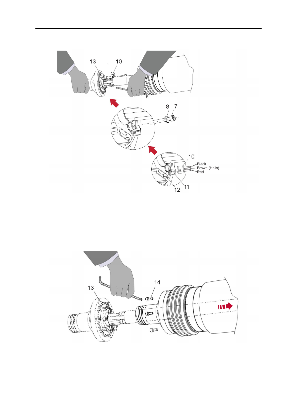
6. If present, insert the control cable plug (10) into the connector (11) and make sure it is
firmly seated.
7 - 3× M5×35 screw 11 - Control cable connector
8 - Washer 12 - 2× Micro switch
10 - Control cable plug 13 - Index pin
7. Gently push back the cable assembly into the robot arm and carefully seat the
RTKSC-2 cover (1) in place. Observe the index pin (13) to be in the correct position.
Make sure the two micro switches (12) are not damaged if present.
8. Insert the three M5 screws (14) and tighten without excessive force.
13. Index pin
14. 3× M5×12 screws
0463 373 101
- 40 -
© ESAB AB 2018

5 INSTALLATION
5.3.3.2 RTKSC-2 electrical connections
NOTA:
After connecting the control cable, secure the cable in order to protect it from getting
caught while the robot is moving.
Usually, the control cable will be directly connected to the wire feeder. See the
manufacturer's documentation for details. The link to the robot control is then
implemented via the power source controller.
RTKSC-2 safety-off mechanism connection
The switch for the safety-off functionality RTKSC-2 is connected through the control cable,
see (3) in the illustration below. This connects to the RTKSC-2 unit via the control cable plug
(1).
The safety-off signal requires a 2-wire connection (black/black) to the safety-off circuit in the
robot control (5).
If a collision is detected, the control circuit (normally closed) will be interrupted (4).
Rating of the control circuit: max. 48 V / 1 A.
1 - Control cable plug 3 - Burndy connector VVV
2 - EURO central connector
Pin dei connettori Burndy
A. Ugello del gas Touch
sense
C. Sensore di collisione
F. 0V
G. Tensione motore +
H. Tensione motore -
D. Sensore di collisione
E. Avanzamento
RTKSC-2 nozzle sense function connection
If the robot control provides a control circuit for nozzle sense functionality.
The connection is accomplished with a 2-wire connection (black/black) to the nozzle sense
circuit in the robot control (5), see illustration below.
0463 373 101
- 41 -
© ESAB AB 2018

5 INSTALLATION
Usually, the control cable will be directly connected to the wire feeder. See the
manufacturer's documentation for details. The link to the robot control is then implemented
via the power source robot interface.
Rating of the control circuit: max. 50 V / 5 A.
PERICOLO!
If the nozzle sense function is not being used, the open end of the control cable on
the power source connection side must be properly isolated in order to avoid short
circuits. During certain problems on the torch head, the full welding potential may be
present on this cable.
AVVISO!
After detection of contact (gas nozzle on work piece), quickly reduce or cut off the
maximum current in the nozzle sense circuit in order to avoid overloading of the
system.
Allowed load max. 1 minute at the rated nominal current.
1 - Control cable plug 3 - Control cable
2 - EURO central connector
5.3.4 RTKSC-2 torch installation
Continue according to section "Torch installation".
0463 373 101
- 42 -
© ESAB AB 2018

5 INSTALLATION
5.4 RTFLC-2 installation
5.4.1 RTFLC-2 mount
1. Remove the three M5 screws (2) from the front cover (3) of the RT FLC-2 torch mount
and carefully pull the cover off the main body (4).
1 - Hexagon wrench 4 mm 3 - RT FLC-2 front cover
2 - 3× M5×12 screws 4 - RT FLC-2 main body
2. Now position the RT FLC-2 main body (4) on the adapter flange (6) so that the index
pin is correctly seated. Attach with the screws (5) enclosed
Fastening torque max. 2.2 Nm (19.5 in.lb).
1 - Hexagon wrench 4 mm 5 - 3× M5×12 hexagon socket screws
4 - RT FLC-2 main body 6 - Adapter flange
5.4.2 RTFLC-2 wire feeder connection
5.4.2.1 Feeding through the robot arm
NOTA:
In order to adjust the wire feeder position to the cable assembly length, it must be
mounted on an adjustable support with a possible movement of ± 2-3 cm (± 1 in.) to
the back and to the front. The length of the cable assembly must be determined
from the centred mounting position of the wire feeder.
0463 373 101
- 43 -
© ESAB AB 2018

5 INSTALLATION
1. Move the robot arm into a completely straight position, see illustration below. Make
sure that (1) axis 6 (rotation around the torch axis) is in 0° position.
2. Move the feeder (3) completely to the back in order to create space for inserting the
cable assembly. If it is not possible to move the feeder sufficiently, it should be
removed from the robot.
3. Insert the cable assembly with the coupling (2) first into the robot arm and feed it
through the robot wrist.
4. The feeder should only be installed again after the correct mounting position with
respect to the cable length has been determined. (See section "Installing the cable
assembly").
AVVISO!
Important! Axis 6 must be in 0° position.
5.4.2.2 RTFLC-2 feeder cabinet connections
When installed for the first time, the position of the wire feeder cabinet must be adjusted to
the length of the cable assembly. First, the robot arm must be fully extended (straight).
AVVISO!
As long as the correct position of the feeder corresponding to the length of the cable
assembly has not been determined, be careful when moving the robot arm and
avoid overstretching the cable. It is helpful to loosen the positioning screws of the
feeder before moving the robot arm to allow the feeder to follow the cable assembly.
0463 373 101
- 44 -
© ESAB AB 2018

5 INSTALLATION
1. Loosen the sliding mechanism of the wire feeder and connect the cable assembly.
Refer to the instruction of the feeder manufacturer.
2. Now adjust the position of the wire feeder to suit the length of the Infiniturn or Helix
cable, as indicated with "A" in the illustration below.
AVVISO!
When adjusting the position of the feeder cabinet, make sure that the cable
assembly is not under stress when the robot arm is in stretched-out position.
It is normal for the cable assembly to sag slightly, it should never be taut.
3. Before securing the wire feeder in its permanent position, ensure that the Euro
connections are tightly connected. Then turn the torch mount down and up again
(rotating on the axis 5), in order not to tighten the cable assembly too much against
the feeder (see illustration above). Once this is done, tighten the feeder in that
position.
4. For water cooled systems, connect the water lines to the cooling circuit. See section
"Cable assemblies for hollow wrist systems" in the TECHNICAL DATA chapter for
indications.
The hose with the blue rubber cap is for cooling water to the torch, the hose with the
red rubber cap returns the heated water. Make sure the hoses will not kink or get
otherwise blocked.
NOTA:
A Helix cable assembly used for a gas cooled system must not be connected
to a cooling circuit. As the water connections are not needed, they may be cut
off.
5. Connect the blow-out hose (black rubber cap) to the corresponding outlet of the wire
feeder.
NOTA:
If the blow-out function is not used, the blow-out hose must be sealed with the
rubber cap enclosed. With Infiniturn systems, the blow-out air must be
supplied to the corresponding connection hose, if it is not permitted to connect
blow-out air to the shield gas connection!
0463 373 101
- 45 -
© ESAB AB 2018

5 INSTALLATION
6. Install the necessary plug on the control cable and connect it to the safety off circuit
interface of the wire feeder (see section "Electrical connections").
5.4.3 RTFLC-2 cable assembly
The cable assembly must be aligned to the intended use in length and design. The type of
cooling for the torch and the cable assembly must be the same (either gas or water cooled
respectively). In order to prevent damage to the torch system and other components, it is
imperative to observe the following instructions.
AVVISO!
• Coordinate the length and design of the cable assembly to suit the range of
action of the robot.
• Do not bend, compress or overstretch the cable assembly.
• Fix the cable assembly such that is can be moved freely and cannot become
entangled.
• Any additional holding devices possibly installed, for example a balancer,
must not crush or bend the cable assembly.
• Extreme turning movements must be avoided in which the cable assembly
may become twisted.
• Chafing on the robot or other objects must be excluded.
5.4.3.1 RTFLC-2 cable assembly installation
In a hollow wrist system the recommended order of installation is to feed the cable assembly
through the robot arm before connecting the cables to the torch mount.
When the cable assembly is correctly installed in the hollow wrist, continue the installation
according to the procedure described below.
NOTA:
For some robots, it may be possible to deviate from this order, and first connect the
cable assembly to the RTKSC-2 and RTFLC-2, then thread the cable from the front
through the robot arm. If in doubt, follow the suggested order.
1. Loosen the three screws (7) with the associated washers and remove them from the
RTFLC-2 cover (1). See illustration below.
2. Install the supplied O-rings (4) into the grooves in the cover (1). For gas cooled
systems, only one O-ring (4a) is needed, for water cooled systems all three O-rings
are needed.
3. Pull the cable assembly approximately 15 cm (6 in.) from the main body (3).
0463 373 101
- 46 -
© ESAB AB 2018

5 INSTALLATION
4. Insert the coupling (2) into the socket of the cover (1) as shown. Align the index pin (6)
with the index hole (5) in the main body and insert completely.
NOTA:
Take great care that the position of the O-rings is not shifted by the index pin
during the assembly.
1 - RT FLC-2 cover 5 - Index hole
2 - Coupling 6 - Index pin
3 - RT FLC-2 main body 7 - 3× M5×35 screws
4 - 3× O-ring for water cooled systems 11 - Control cable connector
5. Insert the three screws (7) with the associated washers (8) and tighten gently with the
enclosed hexagonal wrench, see below illustration.
Fastening torque approximately 2 Nm (18 in.lb).
0463 373 101
- 47 -
© ESAB AB 2018

5 INSTALLATION
6. If present insert the control cable plug (10) into the connector (11) and make sure it is
firmly seated.
7 - 3× M5×35 screw 11 - Control cable connector
8 - Washer 12 - 2× Micro switch
10 - Control cable plug 13 - Index pin
7. Gently push back the cable assembly into the robot arm and carefully seat the
RTFLC-2 cover (1) in place. Observe the index pin (13) to be in the correct position.
Make sure the two micro switches (12) are not damaged if present.
8. Insert the three M5 screws (14) and tighten without excessive force.
13 - Index pin 14 - 3x M5x12 screws
0463 373 101
- 48 -
© ESAB AB 2018
5 INSTALLATION
5.4.4 RTFLC-2 electrical connections
NOTA:
After connecting the control cable, secure the cable in order to protect it from getting
caught while the robot is moving.
Usually, the control cable will be directly connected to the wire feeder. See the
documentation of the manufacturer for details. The link to the robot control is then
implemented via the power source controller.
5.4.4.1 RTFLC-2 hollow wrist system with Infiniturn cable assembly
Connecting the nozzle sense function
If the robot control provides a control circuit for nozzle sense functionality.
The connection is accomplished with a 2-wire connection (black/black) to the nozzle sense
circuit in the robot control (5), see illustration below.
Usually, the control cable will be directly connected to the wire feeder. See the
manufacturer's documentation for details. The link to the robot control is then implemented
via the power source robot interface.
Rating of the control circuit: max. 50 V / 5 A.
PERICOLO!
If the nozzle sense function is not being used, the open end of the control cable on
the power source connection side must be properly isolated in order to avoid short
circuits. During certain problems on the torch head, the full welding potential may be
present on this cable.
AVVISO!
After detection of contact (gas nozzle on work piece), quickly reduce or cut off the
maximum current in the nozzle sense circuit in order to avoid overloading of the
system.
Allowed load max. 1 minute at the rated nominal current.
1 - Control cable plug 3 - Control cable
2 - EURO central connector
0463 373 101
- 49 -
© ESAB AB 2018
5 INSTALLATION
5.4.4.2 RTFLC-2 hollow wrist system with Helix cable assembly
Connecting the nozzle sense function
If the robot control provides a control circuit for nozzle sense functionality.
The connection is accomplished with a 1-wire connection (green) to the nozzle sense circuit
in the robot control (5), see illustration below.
Usually, the control cable will be directly connected to the wire feeder. See the
manufacturer's documentation for details. The link to the robot control is then implemented
via the power source robot interface.
Rating of the control circuit: max. 50 V / 5 A.
PERICOLO!
If the nozzle sense function is not being used, the open end of the control cable on
the power source connection side must be properly isolated in order to avoid short
circuits. During certain problems on the torch head, the full welding potential may be
present on this cable.
AVVISO!
After detection of contact (gas nozzle on work piece), quickly reduce or cut off the
maximum current in the nozzle sense circuit in order to avoid overloading of the
system.
Allowed load max. 1 minute at the rated nominal current.
1 - Control cable plug 3 - EURO central connector
2 - Control cable 4 - Burndy connector
5.5 Torch installation
Be sure to use the correct version of the torch mount and cable assembly (water or gas
cooled).
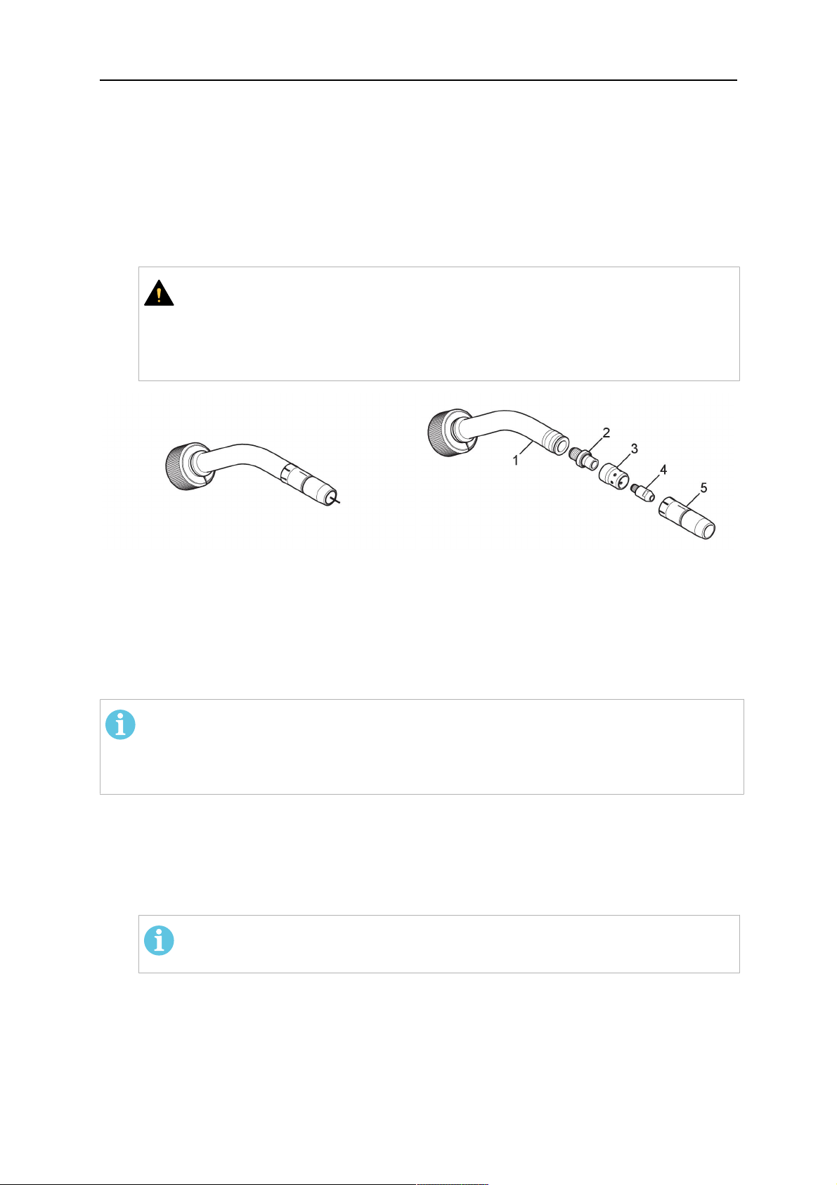
5.5.1 Torch neck equipment
The torch neck, see (1) in the illustration below, must always be equipped to suit the wire
diameter and material.
0463 373 101
- 50 -
© ESAB AB 2018
5 INSTALLATION
1. Select the correct wire guide, contact tip (4), tip holder (2), gas nozzle (5), and gas
diffuser/spatter protection (3). You will find an exact overview and possible alternative
equipment elements for various torch models in the spare parts list. Only use original
ESAB parts; only then is the fitting accuracy ensured.
2. Firmly tighten the tip holder and the contact tip using a suitable tool for example the
enclosed monkey wrench.
3. When using a split wire guide, remove the installed guide nipple including the o-ring
from the torch flange upon delivery if necessary (see section "Installing the neck
liner").
AVVISO!
The torch must be completely equipped before welding, especially the gas
diffuser and/or spatter protection and all necessary insulators have to be
installed according to the spare parts list. Welding without these items may
cause immediate destruction of the torch.
1 - Torch neck 4 - Contact tip
2 - Tip holder 5 - Contact tip
3 - Gas diffuser
5.5.2 Aristo RT torch neck installation
NOTA:
Check the O-rings on the flange of the torch neck before mounting. Replace the
O-rings if damaged or lost. Missing or faulty O-rings will lead to leaks of shielding
gas and coolant.
1. For hollow wrist systems, insert the torch into the torch mount in the correct
orientation, so that the locator pin fits into the slot of the RTKSC-2 or RTFLC-2
interface, see (A) in the illustration below. For standard systems, attach the torch to
the RT flange of the cable assembly, (B) in the illustration below.
Installation is only possible in the correct orientation.
2. Tighten the locking nut of the torch neck.
NOTA:
Only tighten by hand, never use tools or excessive force.
0463 373 101
- 51 -
© ESAB AB 2018
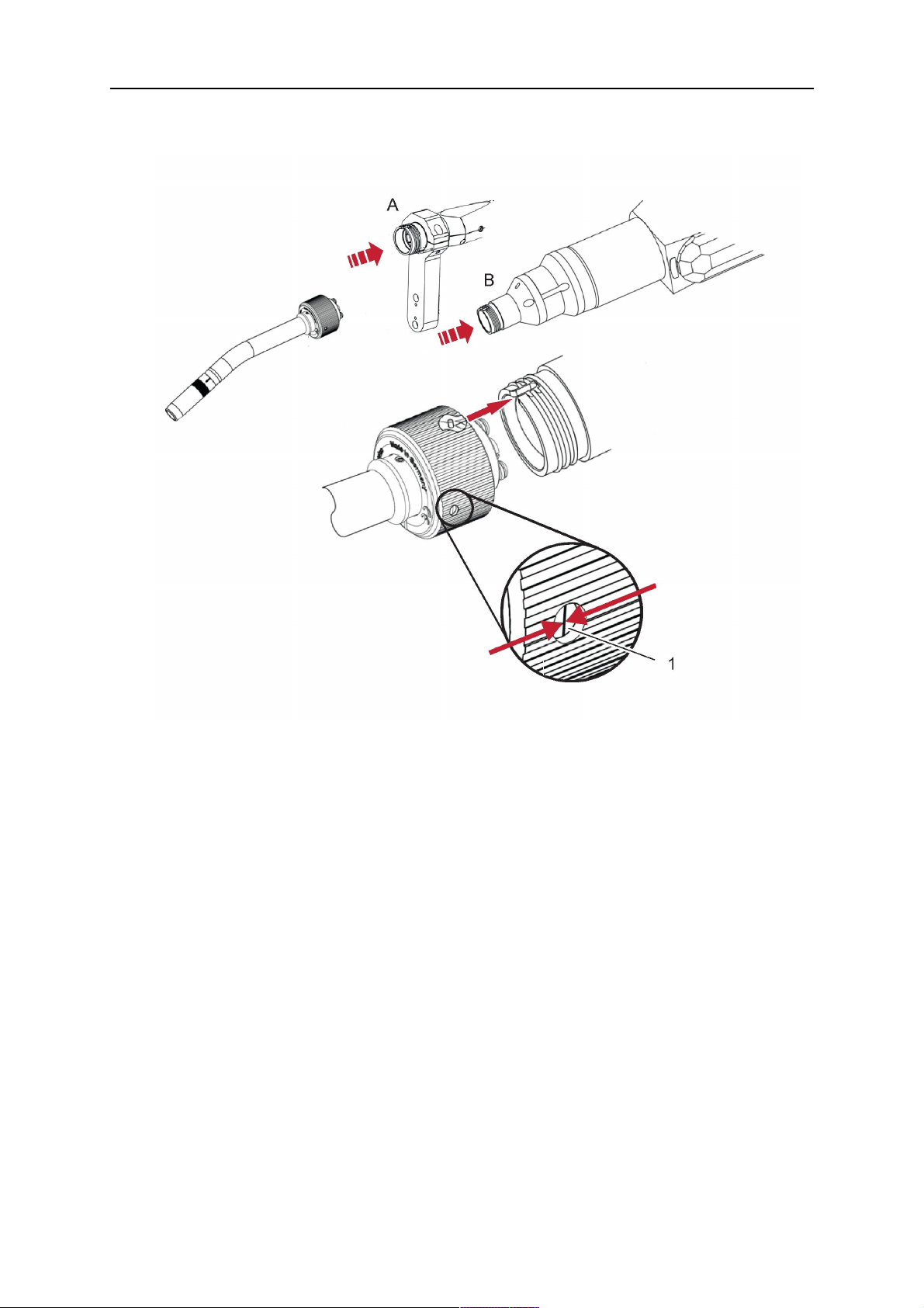
5 INSTALLATION
3. The correct seating of the torch can be checked by means of the window (1). If the
torch has been correctly mounted, no gap should be seen through the window (1).
5.6 Installing the wire guide for standard and hollow Wrist arm
Installing the wire guide
Choose the wire guide or liner depending on the filler wire material and diameter to be used,
see the spare parts list. Accurate performance of the system can only be guaranteed when
using original ESAB wire guides.
The recommended wire guide is the split wire guide, which consists of the neck liner and a
separate guide in the cable assembly. The front part of the wire guide, which is most
stressed, can be exchanged easily and independently of the cable assembly wire guide.
For correct installation, the following steps must be followed (example for Euro central
connector).
5.6.1 Installing the neck liner
The neck liner must be selected to fit the material and diameter of the welding wire, see the
spare parts list.
0463 373 101
- 52 -
© ESAB AB 2018

5 INSTALLATION
1. If present, remove the central guide nipple (1), from the torch neck using a hexagon
wrench (size 6 mm) or a large flat-blade screwdriver.
NOTA:
The guide nipple (1) can only be used with one-piece liners and must not be
used with the standard RT or hollow wrist system.
2. When replacing the neck liner:
Unfasten the sleeve nut and remove the torch neck.
Unfasten the liner nipple using a hexagon wrench (size 6 mm) and remove nipple and
liner from the torch neck.
3. Remove the gas nozzle and the contact tip.
4. Insert the new neck liner (2) into the torch. Carefully tighten the guide nipple using a
suitable tool, e.g. a hex-wrench (size 6 mm) or a large flat-blade screwdriver.
5. Cut the neck liner flush with the tip holder and remove the neck liner from the torch.
6. Install the contact tip.
7. Insert the neck liner again. It will be stopped by the contact tip. Measure the excess
liner sticking out of the neck.
8. Remove the liner again and shorten the front end by the measured length. Carefully
deburr the edge and make sure that the inner hole is not blocked.
9. Reinstall the neck liner and tighten the guide nipple in the neck.
5.6.2 Installing a split wire guide in the cable assembly
The correct liner must be inserted to suit the filler material and the wire diameter, see the
spare parts list.
The wire guide is inserted through the cable assembly from the rear, reaching the guide
nipple that is installed in the flange where the torch neck will be attached. The following
worksteps must be followed in order to correctly determine the wire guide length. (Example
for Euro central connector).
0463 373 101
- 53 -
© ESAB AB 2018
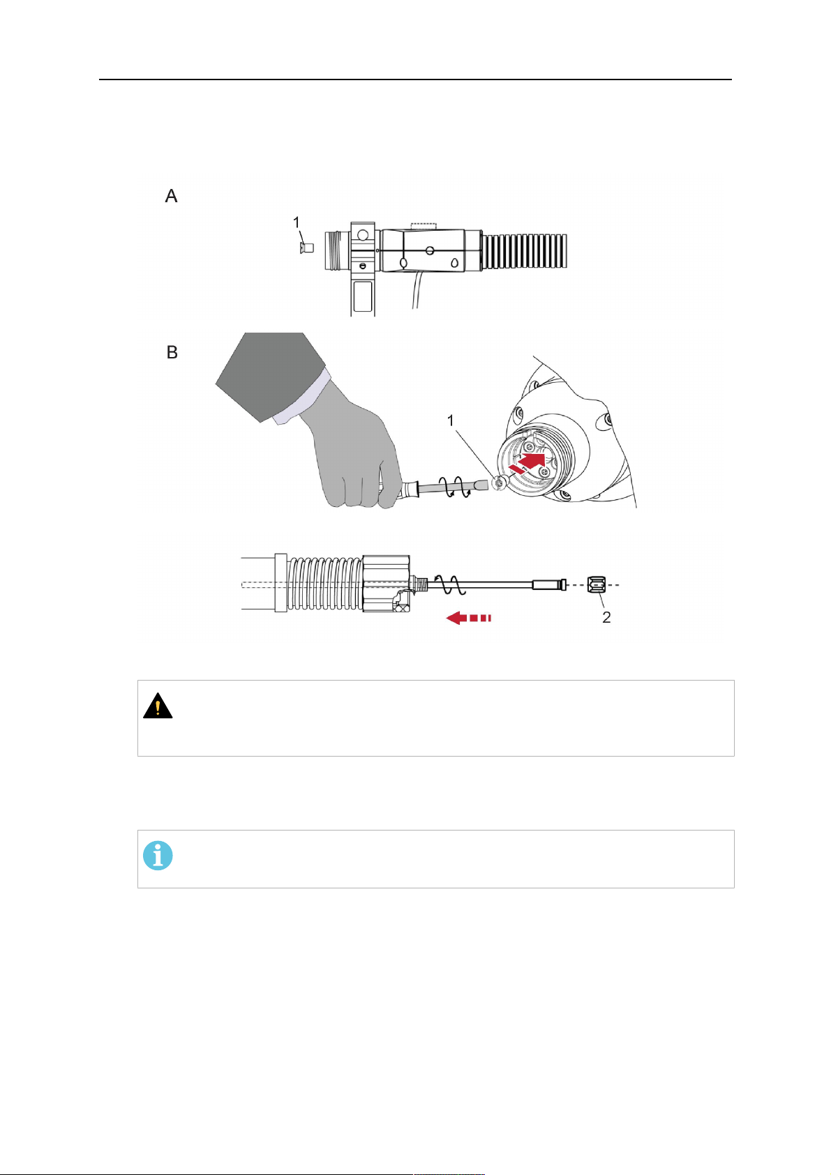
5 INSTALLATION
1. For standard RT system: Install the guide nipple (1) in the center hole of the neck
support flange, see illustration A below.
For hollow wrist system: Install the guide nipple (1) into the torch interface of the
RTKSC-2 / RTFLC-2 cover, see illustration B below.
2. Remove the sleeve nut (2) from the central connector, and remove the old wire guide.
3. Insert the wire guide through the central connection and push forwards as far as it will
go into the guide nipple (1), applying light pressure.
AVVISO!
Ensure that the wire guide has advanced right up to the stop at the front,
rotating and pushing forward gently.
4. Measure the excess length that needs to be cut from the wire guide.
5. Remove the wire guide again and shorten the front end by the measured length.
Steel liner: grind down the burred edges if needed.
Plastic liner: make a clean cut and chamfer the edges (e.g. with a pencil sharpener)
NOTA:
Make sure the inner opening of the liner is not obstructed by the cut wire end.
0463 373 101
- 54 -
© ESAB AB 2018

5 INSTALLATION
6. Reinstall the wire guide and attach the sleeve nut (2).
NOTA:
For hollow wrist systems where Infiniturn and Helix cable assemblies are
used, wire guides should be installed without tension so that the ends of the
liners may rotate freely.
Important note when using a plastic liner:
The wire channel between the drive rolls of the feeder and the central
connector of the torch must be fitted with a plastic liner. Depending on the
design of the feeder, a piece of plastic liner inserted into a brass guide tube
can be used.
During wire run-in, make sure that the wire is fed correctly into the plastic liner
of the torch. If necessary, remove the cable assembly from the feeder and
insert the wire, then reattach.
5.6.3 Installing a continuous wire guide in the cable assembly
Installing a steel liner
The wire guide is inserted through the cable assembly from the rear and reaches to the
contact tip. The following worksteps must be followed for the correct calculation of the length
(example for Euro central connector):
1. Install the torch (see section "Torch neck equipment").
2. Remove the gas nozzle and contact tip from the torch.
3. Remove the sleeve nut (D) from the Euro connector.
4. Push in the liner through the central connector and fix with the sleeve nut.
5. Cut off the liner flush with the nozzle holder. To determine the thread projection of the
contact tip, pull the liner backwards and screw in the contact tip.
6. Push the liner forwards as far as it will go to the contact tip applying light pressure on
the liner and measure the length to be shortened at the rear.
7. Now remove the liner again and cut the excess length measured off it’s front end. If
needed, grind down the burred edges. Make sure the inner opening of the liner is not
obstructed by the cut wire end.
8. The insulation of the liner must be removed after cutting off in the front area, such that
the insulation protrudes out of the RM2 flange by approx. 5 cm. For this, briefly
remove the torch neck.
9. Push the liner back in again and fix with the sleeve nut (D), see above. Re-install the
gas nozzle.
0463 373 101
- 55 -
© ESAB AB 2018

5 INSTALLATION
Installing a plastic liner
1. Mount the torch neck (see section "Torch neck equipment") and equip it with a gas
nozzle and contact tip.
2. Remove the sleeve nut (D) from the Euro connector.
3. Cleanly cut off the liner, slightly break the outer edges, point slightly (e.g. with a pencil
sharpener).
4. Insert the liner through the central connector into the cable assembly with fitted torch.
If it gets stuck, rotate the liner to free it and facilitate installation.
NOTA:
Make sure the liner is completely inserted by rotating it and slightly pushing it
forward, until you can feel it has reached its stop.
5. Mount the nipple (B) and the O-Ring (C), move it to the right position and fix it with the
sleeve nut (D) of the Euro central connector.
6. Measure the required overlap needed inside the wire feeder cabinet and cut the liner
accordingly.
5.7 Adjust the narrow gap contact tip
The adjusting tool RT42-NG is designed for the narrow gap torch necks RT42W-NG,
RT42G-NG and RT 82W-0°NG, torches with curved narrow gap contact tip. It facilitates the
precisely repeatable and fast changing of the curved contact tip.
NOTA:
The adjusting tool must be securely fastened to a stable base, in order to prevent
the position of the device in relation to the robot cannot change unintentionally. If the
exact orientation of the device is lost, the alignment of the contact tip used for the
elaboration of the welding programs can no longer be reproduced with precision.
Select a position within the operating range of the robot for orientation (alignment) of the
contact tip to the torch. Fasten the adjusting tool firmly to a base using the fastening grooves
provided for this purpose. Fastening material is not included with the adjusting tool. Select
fastening material (screws) to suit the existing conditions.
Save all motion sequences and stop positions required to change or align the wearing parts
to a separate robot program.
Before programming the welding tasks: plan at which orientation the contact tip is to stand in
relation to the torch. The torch must then be positioned in the desired rotational position and
the contact tip aligned using the adjusting device. Only then may the welding task be
programmed. If different orientations of the contact tip are required for various welding tasks,
the contact tip has to be aligned to the new position when the welding task is changed.
ATTENZIONE!
The gas nozzle and the torch head become very hot during welding. Always allow
the torch to cool down before replacing wearing parts or adjusting the contact tip.
0463 373 101
- 56 -
© ESAB AB 2018

5 INSTALLATION
Adjust the contact tip
Move the robot torch to a position parallel to
the opening of the adjusting tool (2). Maintain
a sufficient distance to the work table to be
able to comfortably remove the gas nozzle.
Define this position in your robot program as
the wearing parts change position (stop
position 1).
Remove the gas nozzle by pulling it
downwards. Remove the welding wire in the
contact tip if necessary.
Loosen the counter nut (4) of the contact tip
while counter-holding the nozzle holder at the
wrench flat (3).
Unscrew the contact tip including the counter
nut from the nozzle holder and replace the
nozzle holder if necessary.
Completely screw the counter nut (4) onto the
new contact tip. Screw the contact tip
including the counter nut into the nozzle
holder.
Align the contact tip until it is parallel to the
opening of the adjusting tool. If necessary,
slightly unscrew the contact tip so that it can
be easily turned in both directions.
0463 373 101
- 57 -
© ESAB AB 2018

5 INSTALLATION
NOTA:
The contact tip must be able to be
easily moved by hand in both
directions in order to enable the
threading of the adjusting tool.
Place the robot torch or contact tip directly in
front of the opening of the adjusting tool (2)
(stop position 2).
Insert it slowly from the front until it is
completely inserted into the device (stop
position 3).
The contact tip was aligned exactly in the
device during insertion. Now cautiously
tighten the counter nut (4) in this position,
while counter holding the nozzle holder at the
wrench flat.
Slowly move the robot torch out of the
adjusting gauge, return to stop position 1 and
push on the gas nozzle as far as it will go.
Allow the welding wire to run into the contact
tip and bring the robot arm into welding
position.
0463 373 101
- 58 -
© ESAB AB 2018

6 OPERATION
6 OPERATION
AVVISO!
Before starting the system, check the whole installation according to the
manufacturer's instructions and applicable safety regulations.
Check the following to make sure that the system has been installed correctly:
1. Are all parts securely attached (torch, torch mount, flanges, safety-off device, cable
assembly, and wire feeder cabinet)?
2. Are all media hoses connected correctly and protected from damage?
3. Is the EURO central connector or direct connector fastened tightly?
4. Is the cable assembly length correct and suitable for the installation and can the cable
rotate freely? The cable must not be bent sharply. Any risk of the cable getting caught
on another object must be eliminated.
5. Is the control cable of the safety-off circuit connected and functioning? Move torch by
hand to test (RTKSC-2 and RTKS-2 only).
6. Is the torch firmly attached and is it completely equipped?
7. Is the wire guide installed according to the manual?
8. Are all lines and tubes arranged so that they cannot be damaged or bent?
The wire run-in can now be started, either via the wire run-in pushbutton or via the wire run-in
at the feeder.
6.1 Important information for programming (hollow wrist system only)
Fast rotation of axis 6 of the robot will significantly stress the cable assembly. In certain
cases, this can lead to damage or destruction of the cable. In order to maximize the lifetime
of the cable, we strongly suggest respecting the following limitations when programming the
robot.
Position of axis 5 Max. rotational speed of axis 6
0 – 60° 100 % (no limitations)
60° – 80° 300°/sec (approximately 50 % of max. robot speed)
> 80° 120°/sec (approximately 20 % of max. robot speed)
NOTA:
The above values are only indications. For information on the exact rotational speed
limits, refer to the individual robot manual or contact the robot supplier.
To reposition the torch quickly, the robot arm may have to be slightly extended first to achieve
a bending angle of max. 60° of axis 5. In this position, the maximum available rotation speed
of axis 6 can be used.
When using the ESAB Helix cable assembly, the max. rotation of ±270° from the neutral
position must not be exceeded.
0463 373 101
- 59 -
© ESAB AB 2018

6 OPERATION
AVVISO!
While axis 5 is bent more than 60°, the rotational speed of the torch around axis 6
must be limited, see table above.
Otherwise, the cable assembly may be damaged.
0463 373 101
- 60 -
© ESAB AB 2018

7 ASSISTENZA E MANUTENZIONE
7 ASSISTENZA E MANUTENZIONE
ATTENZIONE!
Prima di eseguire interventi di manutenzione sul sistema, spegnere l'alimentazione
principale. Leggere attentamente le norme di sicurezza riportate all'inizio del
presente manuale.
Le torce o i gruppi cablaggi danneggiati non devono essere utilizzati. I difetti noti
devono essere riparati da personale qualificato prima del successivo utilizzo
dell'equipaggiamento.
ATTENZIONE!
Rischio di ustioni L'ugello del gas e la testa della torcia raggiungono temperature
estremamente elevate durante la saldatura. Far raffreddare la torcia prima di
eseguire qualsiasi intervento di manutenzione.
ATTENZIONE!
Al fine di prevenire lesioni personali o danni all'impianto, attenersi alle seguenti
istruzioni:
1. Eventuali interventi di riparazione del supporto torcia RT KSC-2 o RT
FLC-2, del meccanismo di disattivazione di sicurezza RT KS-2, del gruppo
cablaggi o del raccordo liquidi Infiniturn devono essere eseguiti
esclusivamente dall'assistenza ESAB.
2. Il raccordo liquidi Infiniturn non deve mai essere aperto. Contiene
componenti non riparabili dall'utente e lo smontaggio lo renderebbe
inutilizzabile.
3. Non smontare mai l'unità RT KSC-2 o RT KS-2. Si tratta di un meccanismo
a molla. La manipolazione impropria può causare gravi lesioni.
7.1 Controlli e azioni obbligatorie
Prima di ogni utilizzo:
• Verificare che la torcia, la punta di contatto, l'ugello del gas, l'anima del collo, i cavi e
l'attrezzatura nel suo complesso non siano danneggiati.
NOTA:
Per ridurre al minimo i tempi di inattività, si consiglia di alternare due colli torcia,
tenendo sempre un collo torcia equipaggiato a portata di mano e pronto all'uso.
Ogni 8 ore di utilizzo (in base all'applicazione):
• Sostituire la punta di contatto.
Giornaliera:
• Verificare manualmente il corretto funzionamento del meccanismo di disattivazione di
sicurezza.
• Effettuare un'ispezione visiva di eventuali danni, ad esempio, piegature o rotture.
• Verificare che il trainafilo sia in posizione corretta. Il gruppo cablaggi non deve essere
né troppo teso né troppo lento.
0463 373 101
- 61 -
© ESAB AB 2018

7 ASSISTENZA E MANUTENZIONE
• Verificare l'eventuale presenza di perdite nei raccordi dei liquidi e nel raccordo liquidi
Infiniturn.
• Eseguire le operazioni di pulizia e manutenzione della torcia seguendo quanto riportato
nel manuale.
Ogni 40 ore di utilizzo (in base all'applicazione):
• Sostituire le anime dei fili.
• Sostituire le anime del collo.
Ogni settimana o secondo necessità:
• Rimuovere il guida filo e verificare l'eventuale presenza di segni di usura e accumuli di
sporcizia. Sostituire se necessario.
Ogni mese o più spesso in caso di impieghi gravosi (vale a dire più di 8 ore/giorno):
• Erogazione aria compressa nel canale del guida filo (rimozione della punta di contatto e
del guida filo).
• Verificare il serraggio di tutte le viti.
• Ispezione di tutti i raccordi e i flessibili per verificare che non presentino danni.
• Sostituire una volta finito il fusto di filo di saldatura da 250 kg.
Eventuali danni dell'isolamento elettrico devono essere riparati da personale qualificato
prima di poter mettere in funzione il sistema.
0463 373 101
- 62 -
© ESAB AB 2018

8 SOLUZIONE DEI PROBLEMI
8 SOLUZIONE DEI PROBLEMI
Guasto Possibile causa Intervento
Inserimento del
filo impossibile
Il filo di saldatura non è stato stirato
prima di inserirlo nel gruppo
cablaggi
La torcia e il gruppo cablaggi non
sono equipaggiati correttamente per
il diametro e il materiale del filo
Il guida filo non è inserito
correttamente nel gruppo cablaggi
La punta di contatto è ostruita dalla
presenza di detriti
Il guida filo è usurato
Il guida filo è bloccato dalla
presenza di sporcizia e detriti nella
torcia
Se necessario, estrarre
nuovamente il filo di saldatura,
tagliare e sbavare l'estremità e
stirare i primi 10 cm di filo. Quindi,
inserire nuovamente nel gruppo
cablaggi.
Controllare il guida filo (gruppo
cablaggi e collo torcia) e la punta di
contatto.
Tirare leggermente fuori il guida filo
dal connettore europeo. Durante
l'inserimento del guida filo si devono
percepire gli ultimi centimetri
scivolare nel nipplo guida
nell'interfaccia della torcia. In caso
contrario, il guida filo potrebbe
essere troppo corto e non essere
inserito a fondo.
Sostituire la punta di contatto e/o il
guida filo, erogare aria compressa
nel collo della torcia, nel condotto
del guida filo e nel guida filo stesso.
La torcia si
surriscalda in
modo eccessivo
La punta di contatto o il porta punta
non sono serrati correttamente
Il sistema di raffreddamento non
funziona correttamente
Il sistema di raffreddamento non è
collegato correttamente
Utilizzare un attrezzo adeguato per
il serraggio a mano.
Controllare il flusso di acqua, il
livello di riempimento e di pulizia.
Controllare i raccordi (ingresso e
ritorno acqua).
Torcia troppo tesa Osservare i dati tecnici e, se
necessario, scegliere un tipo
diverso.
Gruppo di cavi difettoso Controllare cavi, tubi e raccordi.
0463 373 101
- 63 -
© ESAB AB 2018

8 SOLUZIONE DEI PROBLEMI
Guasto Possibile causa Intervento
Problemi di
inserimento del
filo
L'inserimento
del filo si
interrompe
durante la
saldatura
La punta di contatto è usurata Sostituire la punta di contatto.
Anima usurata/sporca Controllare l'anima; erogare aria
compressa. Sostituire se
necessario.
I materiali di consumo utilizzati non
Verificare l'elenco dei ricambi.
sono idonei al diametro o al
materiale del filo
Saldatrice a filo non configurata
correttamente
Controllare i rulli della saldatrice a
filo, la pressione di contatto e il
freno della bobina.
Il gruppo cablaggi è piegato o è
disposto entro un raggio troppo
piccolo
Controllare il gruppo cablaggi per
verificare che non sia danneggiato.
È possibile inserire l'anima
facilmente? Installare seguendo le
istruzioni. Vedere la sezione
"Installazione del gruppo cablaggi".
Il filo è contaminato Utilizzare un feltro di pulizia.
La bobina del filo è vuota Controllare la quantità di filo di
saldatura presente sulla bobina
nella saldatrice a filo.
È presente un blocco del filo nel
gruppo cablaggi
Controllare l'inserimento del filo
(probabilmente troppo rapido),
controllare la punta di contatto per
verificare che non sia
contaminata/ostruita e pulirla e
sostituirla secondo necessità.
Il processo di
saldatura in
corso si arresta.
Pori nella
giunzione
Filo bruciato reinserito nella punta di
Sostituire la punta di contatto.
contatto o punta di contatto usurata
Meccanismo di disattivazione di
sicurezza attivato.
Ricercare i punti di collisione e
prevenirli. Verificare l'eventuale
presenza di contatti scadenti nella
linea di controllo.
Movimento vorticoso del gas
causato dall'adesione degli spruzzi
Flusso di gas troppo ridotto o
elevato nella torcia
Pulire la testa della torcia, utilizzare
il diffusore del gas / paraspruzzi.
Controllare la portata con lo
strumento di misurazione.
Alimentazione del gas difettosa Controllare la portata e verificare
che non ci siano perdite.
Umidità e contaminazione presenti
sul filo o sul pezzo da lavorare
Controllare il filo e il pezzo da
lavorare, utilizzare una quantità
inferiore o un liquido antispruzzo
differente.
0463 373 101
- 64 -
© ESAB AB 2018

8 SOLUZIONE DEI PROBLEMI
Guasto Possibile causa Intervento
Arco non stabile La punta di contatto è usurata Sostituire la punta di contatto.
Parametri di saldatura non corretti Controllare la configurazione
dell'attrezzatura di saldatura.
Collegamenti elettrici nel circuito
scadenti
Controllare tutti i collegamenti
elettrici (incluso il cavo di massa) tra
l'alimentazione e la torcia o il pezzo
da lavorare per verificare che siano
saldi in posizione.
0463 373 101
- 65 -
© ESAB AB 2018

9 ORDINAZIONE RICAMBI
9 ORDINAZIONE RICAMBI
AVVISO!
Le riparazioni e gli interventi a livello elettrico devono essere effettuati solamente da
tecnici di manutenzione autorizzati da ESAB. Utilizzare solo ricambi e componenti
soggetti a usura originali ESAB.
Le torce ESAB RT modello RTKS-2, RTFL-2, RT-KSC-2, RT-FLC-2, RT42, RT52, RT62,
RT72, RT82, RT42-NG e RT82WNG sono state progettate e collaudate in conformità agli
standard europei e internazionali IEC/EN 60974-7. Spetta al centro di assistenza che ha
effettuato la manutenzione o la riparazione dell'apparecchio accertarsi dell'invariata
conformità del prodotto ai suddetti standard.
I ricambi e i componenti usurati possono essere ordinati dal più vicino rivenditore ESAB; fare
a riferimento al sito Web esab.com. Al momento dell’ordine, indicare il tipo di prodotto, il
numero di serie, la denominazione e il numero del ricambio specificati nell’elenco dei
ricambi. In questo modo si facilita l’invio del pezzo desiderato.
0463 373 101
- 66 -
© ESAB AB 2018

9 ORDINAZIONE RICAMBI
0463 373 101
- 67 -
© ESAB AB 2018

ESAB AB, Lindholmsallén 9, Box 8004, 402 77 Gothenburg, Sweden, Phone +46 (0) 31 50 90 00
http://manuals.esab.com
For contact information visit esab.com
 Loading...