


RT Robo Welding Torch System
RTKS-2, RTFL-2, KSC-2, FLC-2, RT42, RT52,
RT62, RT72, RT82, RT42-NG, RT82WNG
Manual de instruções
0463 373 101 BR 20181227


SUMÁRIO
1
SEGURANÇA .............................................................................................. 5
1.1 Significado dos símbolos ...................................................................... 5
1.2 Precauções de segurança ..................................................................... 5
2
GARANTIA................................................................................................... 9
2.1 Condições de uso pretendido............................................................... 9
3
INTRODUÇÃO ............................................................................................. 10
3.1 Visão geral dos sistemas do maçarico de soldagem ......................... 11
4
DADOS TÉCNICOS ..................................................................................... 13
4.1 Pescoço do maçarico de soldagem ..................................................... 13
4.2 Classificação de tensão......................................................................... 14
4.2.1 Limites do circuito de resfriamento....................................................... 15
4.3 Suporte do maçarico.............................................................................. 15
4.3.1 Suportes do maçarico para o sistema RT padrão................................ 15
4.3.1.1 Mecanismo de desligamento de segurança do RTKS-2 .................. 16
4.3.1.2 Flange intermediário do RTFL-2....................................................... 16
4.3.2 Suportes de maçarico para o sistema de pulso oco ............................ 17
4.3.2.1 Suporte do maçarico RTKSC-2 G/W com mecanismo de
desligamento de segurança ..............................................................
4.3.2.2 Montagem de maçarico rígido RTFLC-2 G/W.................................. 20
4.4 Flanges adaptadores ............................................................................. 20
4.5 Conjuntos de cabos ............................................................................... 20
4.5.1 Conjuntos de cabos para o sistema RT padrão ................................... 21
4.5.2 Conjuntos de cabos para sistemas de pulso oco................................. 22
5
INSTALLATION............................................................................................ 24
5.1 RTKS-2 standard arm installation........................................................ 24
5.1.1 RTKS-2 safety-off mechanism............................................................. 24
5.1.1.1 Torch installation with adjustable mount............................................ 25
5.1.2 Standard arm cable assembly for KS-2 and FL-2 ................................ 27
5.1.3 RTKS-2 wire feeder connection........................................................... 28
5.1.4 RTKS-2 electrical connections ............................................................ 29
5.1.4.1 RTKS-2 safety-off mechanism connection ....................................... 29
5.1.5 RTKS-2 Torch installation.................................................................... 30
5.2 RTFL-2 standard arm installation ........................................................ 31
19
5.2.1 RTFL-2 rigid mount.............................................................................. 31
5.2.2 RTFL-2 torch installation ..................................................................... 33
5.3 RTKSC-2 hollow wrist system installation.......................................... 33
5.3.1 RTKSC-2 mount with safety off mechanism........................................ 33
5.3.2 Mounting the cable assembly............................................................... 34
5.3.2.1 RTKSC-2 feeder cabinet connections .............................................. 35
5.3.3 RTKSC-2 cable assembly ................................................................... 37
5.3.3.1 RTKSC-2 cable assembly installation .............................................. 37
0463 373 101 © ESAB AB 2018

SUMÁRIO
5.3.3.2 RTKSC-2 electrical connections....................................................... 40
5.3.4 RTKSC-2 torch installation .................................................................. 41
5.4 RTFLC-2 installation.............................................................................. 42
5.4.1 RTFLC-2 mount................................................................................... 42
5.4.2 RTFLC-2 wire feeder connection......................................................... 42
5.4.2.1 Feeding through the robot arm.......................................................... 42
5.4.2.2 RTFLC-2 feeder cabinet connections............................................... 43
5.4.3 RTFLC-2 cable assembly.................................................................... 45
5.4.3.1 RTFLC-2 cable assembly installation............................................... 45
5.4.4 RTFLC-2 electrical connections .......................................................... 48
5.4.4.1 RTFLC-2 hollow wrist system with Infiniturn cable assembly........... 48
5.4.4.2 RTFLC-2 hollow wrist system with Helix cable assembly................. 49
5.5 Torch installation.................................................................................... 49
5.5.1 Torch neck equipment .......................................................................... 49
5.5.2 Aristo RT torch neck installation........................................................... 50
5.6 Installing the wire guide for standard and hollow Wrist arm ............. 51
5.6.1 Installing the neck liner......................................................................... 51
5.6.2 Installing a split wire guide in the cable assembly................................ 52
5.6.3 Installing a continuous wire guide in the cable assembly..................... 54
5.7 Adjust the narrow gap contact tip ........................................................ 55
6
OPERATION ................................................................................................ 58
6.1 Important information for programming (hollow wrist system only) 58
7
SERVIÇO E MANUTENÇÃO ....................................................................... 60
7.1 Verificações e ações obrigatórias ........................................................ 60
8
SOLUÇÃO DE PROBLEMAS ..................................................................... 62
9
PEDIDOS DE PEÇAS SOBRESSALENTES .............................................. 64
Direitos reservados para alterar as especificações sem aviso.
0463 373 101 © ESAB AB 2018

1 SEGURANÇA
1 SEGURANÇA
1.1 Significado dos símbolos
Como usado neste manual: Significa Atenção! Fique Atento!
PERIGO!
Significa perigos imediatos que, se não forem evitados, resultarão em
ferimentos pessoais graves e imediatos ou perda da vida.
AVISO!
Significa perigos potenciais que poderiam resultar em ferimentos pessoais
ou perda da vida.
ATENÇÃO!
Significa perigos que poderiam resultar em ferimentos pessoais mais leves.
AVISO!
Antes do uso, leia e entenda o manual de instruções e
siga todas as etiquetas, práticas de segurança do
empregado e Folhas de Dados de Segurança (SDSs).
1.2 Precauções de segurança
Usuários do equipamento ESAB têm a responsabilidade final por garantir que quem trabalhe
com o equipamento ou esteja próximo observe todas as medidas de segurança relevantes.
As medidas de segurança devem atender aos requisitos que se aplicam a este tipo de
equipamento. As recomendações a seguir devem ser observadas além das normas padrão
que se aplicam ao local de trabalho.
Todo o trabalho deve ser realizado por pessoal especializado, bem familiarizado com a
operação do equipamento. A operação incorreta do equipamento pode levar a situações
perigosas, que podem resultar em ferimentos ao operador e danos ao equipamento.
1. Qualquer pessoa que use o equipamento deve estar familiarizada com o seguinte:
○ sua operação
○ local de paradas de emergência
○ sua função
○ precauções de segurança pertinentes
○ soldagem e corte ou outra operação aplicável do equipamento
2. O operador deve garantir que:
○ nenhuma pessoa não autorizada se posicione dentro da área de trabalho do
equipamento quando ele for iniciado
○ nenhuma pessoa esteja desprotegida quando o arco for ativado ou o trabalho
for iniciado com o equipamento
3. O local de trabalho deve:
○ ser adequado para a finalidade
○ estar livre de correntes de ar
0463 373 101
- 5 -
© ESAB AB 2018

1 SEGURANÇA
4. Equipamento de proteção pessoal:
○ Use sempre o equipamento de proteção pessoal recomendado, como óculos de
segurança, roupas à prova de chamas, luvas de segurança
○ Não use itens soltos, como lenços, braceletes, anéis etc., que podem ficar
presos ou ocasionar incêndio
5. Precauções gerais:
○ Verifique se o cabo de retorno está conectado com firmeza
○ O trabalho em equipamento de alta tensão só pode ser executado por um
eletricista qualificado
○ O equipamento extintor de incêndio deve estar nitidamente marcado e próximo,
ao alcance das mãos
○ A lubrificação e a manutenção não devem ser realizadas no equipamento
durante a operação
AVISO!
Solda e corte a arco podem ser prejudiciais para você e as demais pessoas. Tome
medidas de precaução ao soldar e cortar.
CHOQUE ELÉTRICO - pode matar
• Instale e aterre a unidade de acordo com o manual de instruções.
• Não toque em peças elétricas sob tensão nem em eletrodos com a pele
desprotegida, luvas úmidas ou roupas úmidas.
• Isole-se do trabalho e do piso.
• Certifique-se quanto à segurança de sua posição de trabalho
CAMPOS MAGNÉTICOS E ELÉTRICOS - podem ser perigosos à saúde
• Os soldadores com marca-passos devem consultar seus médicos antes
de soldarem. O EMF pode interferir em alguns marca-passos.
• A exposição a EMFs pode ter outros efeitos na saúde que são
desconhecidos.
• Os soldadores devem usar os procedimentos a seguir para minimizar a
exposição a EMFs:
○ Passe os cabos do eletrodo e de trabalho juntos pelo mesmo lado do
seu corpo. Prenda-os com fita sempre que possível. Não coloque
seu corpo entre o maçarico e os cabos de trabalho. Nunca enrole o
cabo do maçarico ou de trabalho em seu corpo. Mantenha a fonte de
alimentação da solda e os cabos o mais longe possível do seu
corpo.
○ Conecte o cabo de trabalho à peça de trabalho o mais próximo
possível da área que está sendo soldada.
FUMAÇAS E GASES - podem ser perigosos à saúde
• Mantenha a cabeça distante deles.
• Mantenha o ambiente ventilado, exaustão no arco, ou ambos, para manter
a fumaça e os gases fora da sua zona de respiração e da área geral.
Os RAIOS DE ARCOS podem danificar os olhos e queimar a pele.
0463 373 101
• Proteja os olhos e o corpo. Use a tela de soldagem e lente de filtro
corretas, e vista roupas de proteção.
• Proteja os espectadores com telas ou cortinas adequadas.
RUÍDO - Ruído excessivo pode danificar a audição
Proteja os ouvidos. Use tampões para os ouvidos ou outra proteção auditiva.
- 6 -
© ESAB AB 2018

1 SEGURANÇA
PEÇAS MÓVEIS - Podem causar danos
• Mantenha todas as portas, painéis e tampas fechadas e firmes no local.
Apenas pessoas qualificadas devem remover as tampas para manutenção
e solução de problemas conforme necessário. Reinstale os painéis ou
tampas e feche as portas quando o serviço estiver concluído e antes de
dar a partida no motor.
• Desligue o motor antes de instalar ou conectar uma unidade.
• Mantenha as mãos, cabelos, roupas frouxas e ferramentas longe das
partes em movimento.
PERIGO DE INCÊNDIO
• Faíscas (respingos) podem causar incêndio. Certifique-se de que não haja
materiais inflamáveis nas proximidades.
• Não use em recipientes fechados.
FUNCIONAMENTO INCORRETO - Ligue para obter auxílio de um especialista em caso
de funcionamento incorreto.
PROTEJA OS OUTROS E A SI MESMO!
ATENÇÃO!
Este produto destina-se exclusivamente a soldagem a arco.
AVISO!
Não use a fonte de alimentação para descongelar tubos congelados.
ATENÇÃO!
Os equipamentos Classe A não se destinam ao uso em
locais residenciais nos quais a energia elétrica é
fornecida pelo sistema público de fornecimento de
baixa tensão. Pode haver dificuldades potenciais em
garantir a compatibilidade eletromagnética de
equipamentos classe A nesses locais, em função de
perturbações por condução e radiação.
NOTA:
Descarte o equipamento eletrônico em uma
instalação de reciclagem!
Em cumprimento à Diretiva europeia 2012/19/EC sobre
Resíduos de equipamentos elétricos e eletrônicos, e
sua complementação em conformidade com a lei
nacional, equipamentos elétricos e/ou eletrônicos que
tenham atingido o fim da vida útil devem ser
descartados em uma instalação de reciclagem.
Na condição de pessoa responsável pelo equipamento,
é sua responsabilidade obter informações sobre
estações de coleta aprovadas.
Para obter mais informações, contate o revendedor
ESAB mais próximo.
0463 373 101
- 7 -
© ESAB AB 2018

1 SEGURANÇA
ESAB tem uma variedade de acessórios de soldagem e equipamento de proteção
pessoal para compra. Para informações sobre pedidos, entre em contato com o
revendedor local ESAB ou visite-nos em nosso site.
0463 373 101
- 8 -
© ESAB AB 2018

2 GARANTIA
2 GARANTIA
Antes da entrega, nossos produtos são cuidadosamente verificados. A ESAB verifica se
cada produto está livre de defeitos de material e defeitos humanos no momento da entrega
e se está funcionando de acordo com a sua utilização prevista.
A ESAB oferece garantia sobre os defeitos de material e humanos, de acordo com as
exigências legais. Os consumíveis estão isentos dessa garantia.
A garantia não cobre quaisquer danos ou defeitos funcionais resultantes de:
• sobrecarga, abuso ou desvio do uso previsto do produto
• colisões ou acidentes
• não conformidade com as instruções declaradas nas instruções de operação
• instalação ou montagem incorreta
• manutenção insuficiente
• modificação do produto do seu estado original
• influências químicas
• desgaste normal
A ESAB não assume nenhuma responsabilidade pela substituição ou reparação de peças
defeituosas.
2.1 Condições de uso pretendido
1. O produto destina-se ao uso industrial e comercial e só deve ser utilizado por pessoal
treinado. O fabricante não se responsabiliza por quaisquer danos ou acidentes
resultantes de uso inadequado.
2. O Sistema de Soldagem Robótica Aristo® RT foi projetado e produzido com
tecnologia de ponta, e é seguro e confiável quando manuseado, instalado e mantido
por pessoal treinado. As instruções de instalação, operação e manutenção descritas
neste documento devem ser seguidas.
3. O Sistema de Soldagem Robótica Aristo® RT só pode ser instalado, operado e
submetido à manutenção por pessoal treinado. Os regulamentos de instalação,
operação e manutenção detalhados neste manual devem ser seguidos.
4. O Sistema de Soldagem Robótica Aristo® RT só pode ser usado com a finalidade
prevista pelo fabricante dentro da estrutura de seus dados técnicos e com os
sistemas de manuseio automatizado. O tipo de maçarico deve ser selecionado para
se adequar à tarefa de soldagem.
5. O Sistema de Soldagem Robótica Aristo® RT foi projetado para ser usado como um
sistema completo. A incorporação de componentes de outros fabricantes no sistema
não é permitida.
6. O RT KS-2 e o RT KSC-2 devem ser usados apenas como mecanismos de parada de
emergência dentro de suas especificações técnicas e em combinação com um
conjunto de cabos de braço padrão RT (KS-2), Infiniturn ou Helix (KSC-2), flange
adaptador ESAB, incluindo suportes de maçarico RT (KS-2) e um maçarico de
soldagem Aristo RT.
7. Nenhum óleo ou fluido antirespingo deve ser adicionado ao gás soprado. A ESAB
não garante a resistência química a essas substâncias. A ESAB recomenda usar a
unidade de pulverização ESAB para aplicar a quantidade mínima de fluido
antirespingo ao maçarico e, dessa forma, proteger o ambiente.
8. O produto deve ser mantido seco e protegido contra umidade quando transportado,
armazenado ou usado.
9. O sistema foi projetado para temperaturas ambientais entre 5 °C a 40 °C (41 °F a 104
°F). Caso esses limites sejam excedidos, uma ação específica é necessária. Em caso
de risco de congelamento, use um líquido de arrefecimento adequado.
0463 373 101
- 9 -
© ESAB AB 2018

3 INTRODUÇÃO
3 INTRODUÇÃO
Os sistemas de maçarico de soldagem RT são desenvolvidos para soldagem MIG/MAG
totalmente automática usando robôs. Os sistemas consistem em uma série de tubos de
maçaricos Aristo RT projetados para uso robótico, suportes de maçarico, conjuntos de cabos
otimizados para uso robótico e recursos de desligamento de segurança para evitar danos ao
sistema em caso de colisão.
O sistema de soldagem RT padrão oferece proteção contra colisão por meio do uso do RT
KS-2, que é uma funcionalidade mecânica de desligamento de segurança por mola. Ele
pode ser substituído opcionalmente pelo RT FL-2 para aproveitar a função de detecção de
colisão do sistema de controle robótico. O sistema de soldagem RT padrão pode ser usado
com diversos tipos de conjuntos de cabos.
Os suportes de maçarico RTKSC-2 e RTFLC-2 com conjuntos de cabo Infiniturn ou Helix
são destinados para uso em sistemas de soldagem por robô de pulso oco projetados para
aplicações de soldagem avançadas. O mecanismo de desligamento de segurança no
suporte do maçarico RTKSC-2 permite uma grande deflexão elástica do maçarico em caso
de colisão. Os conjuntos de cabos Infiniturn e Helix são simples de instalar e fornecem um
sistema altamente confiável com recursos precisos de manobra.
Em combinação com os já conhecidos maçaricos de soldagem robóticos Aristo RT, esses
constituintes criam um sistema altamente confiável e duradouro que necessita apenas da
manutenção básica.
O manual de instruções está incluso na entrega dos suportes de maçaricos e conjuntos de
cabos.
Os números de pedido ESAB, acessórios disponíveis, peças de reposição e peças de
desgaste são encontrados na lista de peças de reposição.
0463 373 101
- 10 -
© ESAB AB 2018

3 INTRODUÇÃO
3.1 Visão geral dos sistemas do maçarico de soldagem
Sistema RT padrão
Para obter uma descrição detalhada,
consulte a seção correspondente no capítulo
DADOS TÉCNICOS:
1. Pescoço do maçarico
Consulte "Maçarico de soldagem".
2. Conjunto de cabos
Consulte "Conjuntos de cabos para
o sistema RT padrão".
3. Suporte do maçarico
Consulte "Suportes do maçarico
para o sistema RT padrão".
4. Mecanismo de desligamento de
segurança do RTKS-2
Consulte "Mecanismo de
desligamento de segurança do
RTKS-2".
5. Flange intermediário do RTFL-2
Consulte "Flange intermediário do
RTFL-2".
6. Flange adaptador (se necessário)
Consulte "Flanges adaptadores".
0463 373 101
- 11 -
© ESAB AB 2018

3 INTRODUÇÃO
Sistema de pulso oco
Para obter uma descrição detalhada,
consulte a seção correspondente no capítulo
DADOS TÉCNICOS:
1. Pescoço do maçarico
Consulte "Maçarico de soldagem".
2. Suporte do maçarico do
RTKSC-2
Consulte "Suporte do maçarico do
RTKSC-2 com mecanismo de
desligamento de segurança".
3. Suporte do maçarico do RTFLC-2
Consulte "Suporte do maçarico
rígido do RTFLC-2".
4. Flange adaptador
Consulte "Flanges adaptadores".
5. Conjunto de cabos Helix ou
Infiniturn
Consulte "Conjuntos de cabos para
sistemas de pulso oco".
0463 373 101
- 12 -
© ESAB AB 2018

4 DADOS TÉCNICOS
4 DADOS TÉCNICOS
4.1 Pescoço do maçarico de soldagem
Escolha o modelo do maçarico de acordo com a aplicação de soldagem. O ciclo de trabalho
e a capacidade necessários, o método de resfriamento e o diâmetro do fio devem ser
considerados. Se houver requisitos maiores, por exemplo, causados por peças de trabalho
pré-aquecidas ou pela alta reflexão de calor nos cantos, considere esses fatores
selecionando um maçarico de soldagem com reserva adequada na classificação de
potência.
Os maçaricos de soldagem RT destinam-se ao uso com fontes de alimentação de soldagem
em conformidade com a CE para os processos de soldagem MIG (Metal Inert Gas), MAG
(Metal Active Gas) e Brasagem MIG com fios redondos comerciais. Não use o maçarico
para outros processos.
Para soldagem por arco pulsado de aço ou alumínio, deve ser usado o maçarico resfriado a
água RT82W.
Consulte os modelos de maçarico disponíveis abaixo.
Modelo do maçarico
Método de
resfriamento
Gás de proteção Classificação
RT42G Resfriado a gás CO
Resfriado a gás 300A / 100%
Resfriado a gás Mistura 350A / 60%
Resfriado a gás 250A / 100%
RT42W Resfriado a água CO
Resfriado a água 420A / 100%
Resfriado a água Mistura 350A / 60%
Resfriado a água 350A / 100%
RT52G Resfriado a gás CO
Resfriado a gás 300A / 100%
Resfriado a gás Mistura 350A / 60%
Resfriado a gás 250A / 100%
RT52W Resfriado a água CO
Resfriado a água 470A / 100%
Resfriado a água Mistura 400A / 60%
2
2
2
2
420A / 60%
420A / 60%
420A / 60%
470A / 60%
Resfriado a água 400A / 100%
RT62G Resfriado a gás CO
Resfriado a gás 340A / 100%
Resfriado a gás Mistura 420A / 60%
Resfriado a gás 290A / 100%
RT62W Resfriado a água CO
Resfriado a água 530A / 100%
Resfriado a água Mistura 450A / 60%
Resfriado a água 450A / 100%
0463 373 101
- 13 -
2
2
500A / 60%
530A / 60%
© ESAB AB 2018

4 DADOS TÉCNICOS
Modelo do maçarico
Método de
resfriamento
RT72G Resfriado a gás CO
Gás de proteção Classificação
2
480A /60%
Resfriado a gás 320A / 100%
Resfriado a gás Mistura 400A / 60%
Resfriado a gás 270A / 100%
RT72W Resfriado a água CO
2
480A / 60%
Resfriado a água 430A / 100%
Resfriado a água Mistura 480A / 60%
Resfriado a água 430A / 100%
RT82W Resfriado a água CO
2
600A / 60%
Resfriado a água 600A / 100%
Resfriado a água Mistura 550A / 60%
Resfriado a água 550A / 100%
Os valores para a classificação do maçarico e o ciclo de trabalho são válidos por um ciclo de
10 minutos.
Os dados técnicos são válidos para uma aplicação padronizada utilizando as peças de
desgaste/reposição padrão. A classificação do maçarico é reduzida ao usar o modo de
transferência de metal de arco pulsado.
Faixas de temperatura Armazenamento: -15-50°C (5-122°F)
Operação: 5–40°C (41–104°F)
Gás soprado Máximo de 10 bar, mangueira de gás
separada
Peso total (pescoço do maçarico, mecanismo
Aproximadamente 5 kg
de segurança, suporte do maçarico e
conjunto de cabos de 1 m)
4.2 Classificação de tensão
Tensão/amperagem máxima permitida
Sistema do maçarico de soldagem completo 141 V (valor de pico para soldagem)
Circuito de controle de desligamento de
segurança do RTKS-2
Botão do RTKS-2
Circuito de controle de desligamento de
segurança do RT KSC-2
Uso da funcionalidade de detecção de bicos
com um conjunto de cabos padrão
24 V/1 A
48 V/0,1 A
48 V
50 V/5 A
(Carga máxima permitida durante 1 minuto
na corrente nominal considerada)
Uso da funcionalidade de detecção de bicos
com um conjunto de cabos Helix ou Infiniturn
50 V/5 A
(Carga máxima permitida durante 1 minuto
na corrente nominal considerada)
As classificações indicadas referem-se a um caso de uso padronizado.
0463 373 101
- 14 -
© ESAB AB 2018

4 DADOS TÉCNICOS
Para classificações de conjunto de cabos, consulte a seção "Conjuntos de cabos".
4.2.1 Limites do circuito de resfriamento
Válido somente para a versão resfriada a água.
Taxa mínima de vazão de
água:
1,0 l/min (1,1 quarts/min)
Pressão mínima da água: 2,5 bar (36,3 psi)
Pressão máxima da água: 3,5 bar (50,8 psi)
Temperatura de entrada: Máximo de 40 °C (104 °F)
Temperatura de retorno: Máximo de 60 °C (140 °F)
Capacidade de resfriamento: Mínimo de 1.000 W, dependendo da aplicação
ATENÇÃO!
Temperaturas de retorno acima de 60 °C (140 °F) podem causar danos ou destruir
o conjunto de cabos.
4.3 Suporte do maçarico
O tipo de suporte do maçarico necessário depende do design do sistema do maçarico de
soldagem RT e da escolha de dispositivos de desligamento de segurança. Consulte a seção
"Visão geral dos sistemas do maçarico de soldagem".
Componente Peso aproximado
Suporte do maçarico (para o sistema padrão) 0,43 kg
Mecanismo de desligamento de segurança
0,85 kg
do RTKS-2 (para sistema padrão)
Flange intermediário do RTFL-2 (para
0,35 kg
sistema padrão)
Suporte de maçarico do RTKSC-2 (para
1,90 kg
sistema de pulso oco)
Suporte de maçarico rígido do RTFLC-2
1,22 kg
(para sistema de pulso oco)
Maçarico de soldagem robótico 0,66 kg
4.3.1 Suportes do maçarico para o sistema RT padrão
Para sistemas RT padrão, o suporte do maçarico é instalado no mecanismo de
desligamento de segurança do RTKS-2 (como alternativa, no flange intermediário do
RTFL-2), prendendo o conjunto de cabos e o pescoço do maçarico conectado.
Selecione o suporte do maçarico de acordo com o tipo de maçarico e sua geometria. Vários
tipos de suporte podem ser usados. Consulte a lista de peças de reposição para saber quais
são os suportes de maçaricos disponíveis para o sistema RT padrão.
0463 373 101
- 15 -
© ESAB AB 2018

4 DADOS TÉCNICOS
Suporte do maçarico para robôs de braço padrão
4.3.1.1 Mecanismo de desligamento de segurança do RTKS-2
O mecanismo de desligamento de segurança do RTKS-2 é um dispositivo com suporte por
mola que protege o robô e o sistema de maçarico em caso de colisão.
NOTA:
Não desmonte o RTKS-2.
4.3.1.2 Flange intermediário do RTFL-2
O flange rígido intermediário do RTFL-2 pode ser usado em vez do RTKS-2, caso o robô
tenha um sistema eletrônico de detecção de colisão.
0463 373 101
- 16 -
© ESAB AB 2018

4 DADOS TÉCNICOS
4.3.2 Suportes de maçarico para o sistema de pulso oco
No sistema de pulso oco, os pinos do maçarico de soldagem Aristo RT são conectados ao
suporte do maçarico KSC-2 ou FLC-2.
O suporte do maçarico RTKSC-2 permite uma deflexão elástica do maçarico em caso de
colisão. Ao mesmo tempo, um contato elétrico é aberto, sinalizando ao controle do robô para
parar. Depois de redefinir o erro, a geometria inicial e o Ponto Central de Ferramentas (TCP,
Tool Center Point) do maçarico serão alcançados com alta precisão. O sistema funciona
exclusivamente de forma mecânica e é carregado por mola.
O suporte do maçarico RTFLC-2 não possui função de desligamento de segurança
integrada.
É recomendado para sistemas de pulso oco RTKSC-2 G/W (alternativamente, RRTFLC-2
G/W). Esse suporte do maçarico pode ser usado com maçaricos resfriados a gás e a água
da série Aristo RT.
RTKSC-2 G/W RTFLC-2 G/W
Princípio funcional do
mecanismo de desligamento
Mecânico Não aplicável (montagem
rígida)
de segurança
Força de liberação axial (Fz) 650 N Não aplicável (montagem
rígida)
Torque de liberação no eixo
transversal (Mx)
24 Nm Não aplicável (montagem
rígida)
Reinicie após a liberação Automático Não aplicável (montagem
rígida)
Repetibilidade Lateral de ± 0,1 mm no TCP
de um maçarico Aristo RT
Não aplicável (montagem
rígida)
padrão
Deflexão máxima Aprox. ± 8° Não aplicável (montagem
rígida)
0463 373 101
- 17 -
© ESAB AB 2018

4 DADOS TÉCNICOS
Interruptor de segurança Normalmente fechado
Carga elétrica máxima de 48
V/1 A
Circuito de controle elétrico
para a função de detecção do
bico
Classificação:
• Para conjuntos de cabo
Helix: máximo de 50
VCC/5 A, máximo de 1
minuto
Após a detecção de
contato, desconecte
rapidamente a tensão
de detecção.
• Para conjuntos de
cabos Infiniturn, a
função de detecção do
bico possui
funcionalidade limitada.
Entre em contato com a
ESAB para uma
investigação detalhada
de possíveis soluções
em sua aplicação.
Não aplicável (montagem
rígida)
Classificação:
• Para conjuntos de cabo
Helix: máximo de 50
VCC/5 A, máximo de 1
minuto
• Para conjuntos de
cabos Infiniturn: máximo
de 50 VCC/1 A, máximo
de 1 minuto
Após a detecção de contato,
desconecte rapidamente a
tensão de detecção.
Classificação de tensão Tensão máxima permitida
para o circuito de controle de
desligamento de segurança:
48 V.
0463 373 101
- 18 -
© ESAB AB 2018

4 DADOS TÉCNICOS
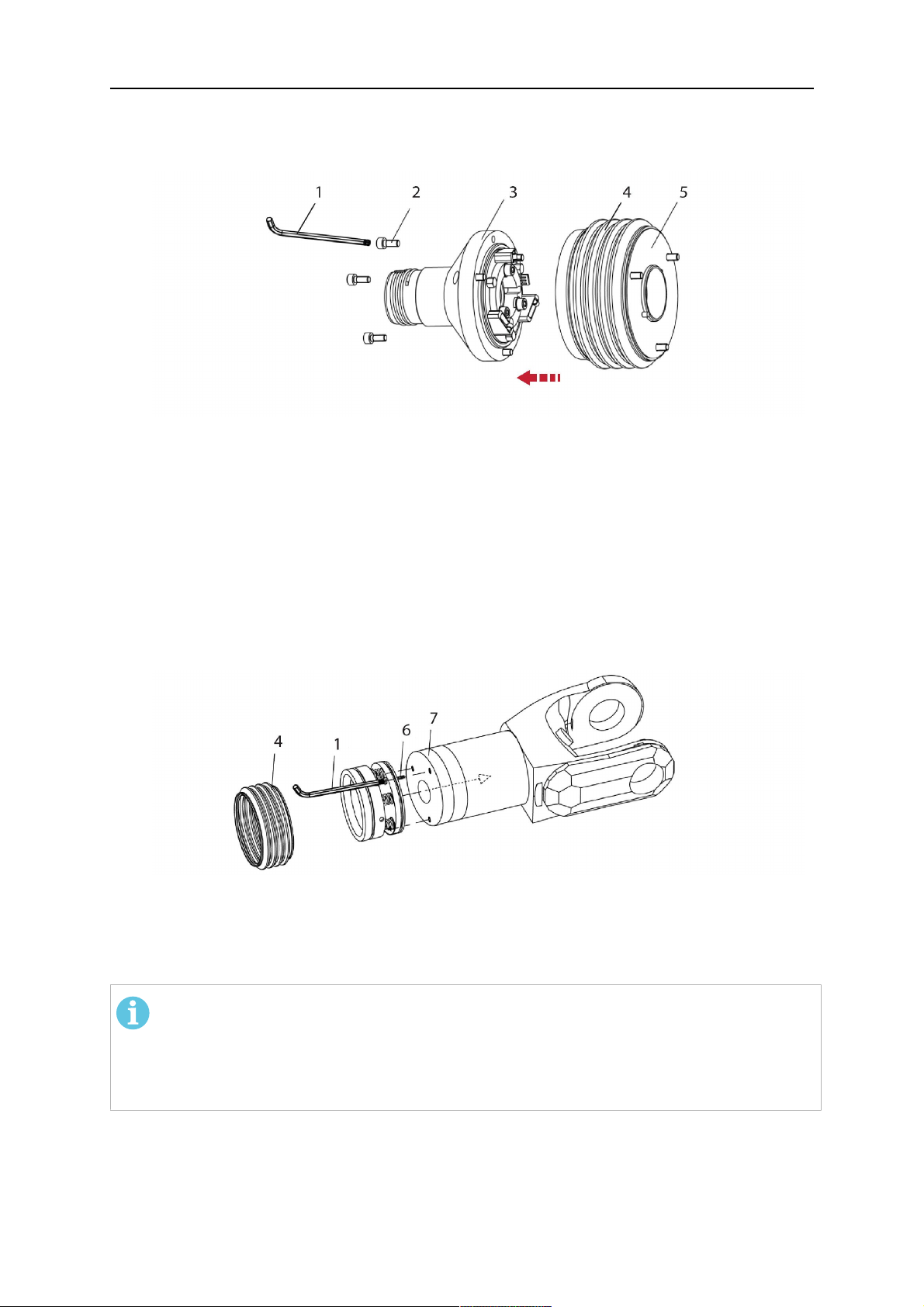
4.3.2.1 Suporte do maçarico RTKSC-2 G/W com mecanismo de desligamento de
segurança
Item Descrição Função
1 Suporte do pescoço do
Interface do maçarico Aristo RT
maçarico
2 Tampa do RTKSC-2 Montagem com interfaces de cabo e maçarico
3 Capa de borracha Proteção do mecanismo de desligamento de
segurança
4 Corpo principal do RTKSC-2 Permite uma deflexão mecânica durante uma
colisão
5 Flange adaptador Interface de isolamento para o punho do robô (deve
se encaixar no robô específico)
6 Pino indicador Para alinhamento preciso com o flange adaptador
7 Conector do cabo de controle Conexão elétrica para o sinal de colisão e a função
de detecção do bico
8 Microinterruptor Sensor de detecção de colisão
0463 373 101
- 19 -
© ESAB AB 2018

4 DADOS TÉCNICOS
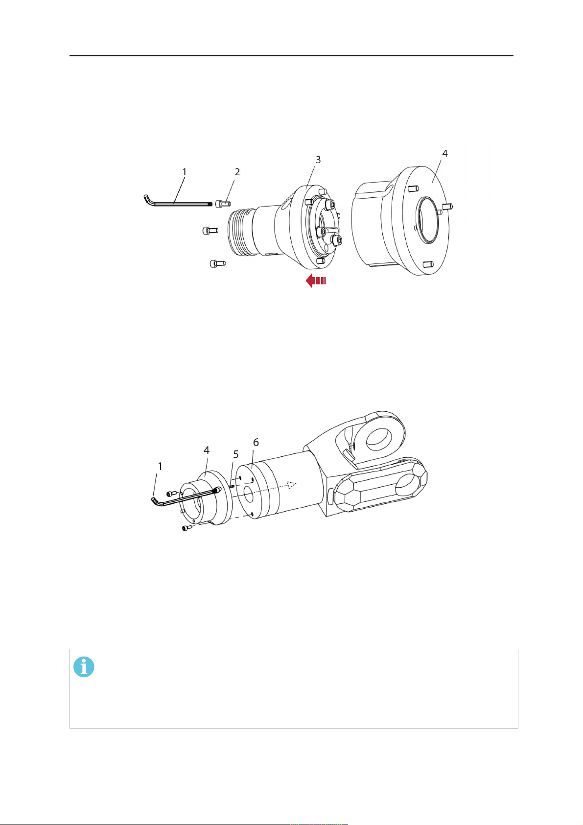
4.3.2.2 Montagem de maçarico rígido RTFLC-2 G/W
Item Descrição Função
1 Suporte do pescoço do
Interface do maçarico Aristo RT
maçarico
2 Tampa do RTFLC-2 Montagem com interfaces de cabo e maçarico
3 Corpo principal do RTFLC-2 Permite uma deflexão mecânica durante uma
colisão
4 Pino indicador Para alinhamento preciso com o flange adaptador
5 Flange adaptador Interface de isolamento para o punho do robô (deve
se encaixar no robô específico)
6 Conector do cabo de controle
(3 polos)
Conexão elétrica para a função de detecção do bico
(se aplicável)
4.4 Flanges adaptadores
Escolha o flange adaptador necessário para a instalação no braço do robô, dependendo do
tipo de robô. Flanges adaptadores para todos os sistemas padrão e de pulso oco adequados
estão disponíveis, consulte a lista de peças sobressalentes.
4.5 Conjuntos de cabos
A conexão com o alimentador de fios é estabelecida através do conjunto de cabos, as
versões disponíveis dependem principalmente do design do sistema e do meio de
resfriamento (gás ou água). Consulte a lista de peças sobressalentes.
As classificações são válidas para cabos de 1 a 5 m.
0463 373 101
- 20 -
© ESAB AB 2018

4 DADOS TÉCNICOS
Conjunto de cabos
padrão
Classificação (ciclo de
10 minutos)
Resfriado a gás (gás
misto)
Ciclo de trabalho de
máximo de 500
A/60%
Ciclo de trabalho de
máximo de 350
A/100%
Classificação (ciclo de
10 minutos)
Resfriado a água
Ciclo de trabalho de
máximo de 600
A/100%
Faixa rotacional Rotatabilidade
limitada
Peso
Resfriado a gás
1,2 m de
comprimento:
2,35 kg
Peso
Resfriado a água
1,2 m de
comprimento:
2,35 kg
Infiniturn Helix
Ciclo de trabalho de
máximo de 400
A/60%
Ciclo de trabalho de
máximo de 320
A/100%
Ciclo de trabalho de
máximo de 550
A/100%
Ciclo de trabalho de
máximo de 400
A/60%
Ciclo de trabalho de
máximo de 320
A/100%
Ciclo de trabalho de
máximo de 550
A/100%
Totalmente giratório ± 270° da posição
neutra
1,0 m de
comprimento:
2,0 kg
1,0 m de
comprimento:
2,0 kg
1,0 m de
comprimento:
2,0 kg
1,0 m de
comprimento:
2,0 kg
4.5.1 Conjuntos de cabos para o sistema RT padrão
Pinos do conector tipo Burndy
A. Bico de gás de detecção
de toque
C. Sensor de colisão
D. Sensor de colisão
E. Avanço
F. 0V
G. + Tensão do motor
H. - Tensão do motor
Item Descrição Função
1 Flange de suporte do pescoço Interface do maçarico
2 Tampa protetora Protege o conjunto do cabo contra danos
0463 373 101
- 21 -
© ESAB AB 2018

4 DADOS TÉCNICOS
Item Descrição Função
3 Conector tipo Burndy, 12 polos Conexão elétrica entre o desligamento de
segurança e o alimentador de fios
4 Cabo de controle Para KS-2 (desligamento de segurança e botão)
5 Conector EURO Conexão de alimentação do fio
6 Mangueira de sopro (tampa
preta)
7 Entrada de água (tampa azul)
8 Retorno de água (tampa
Para limpar o maçarico com ar comprimido após o
ciclo de limpeza
Entrada de água para resfriamento do maçarico
Retorno de água da água aquecida do maçarico
1)
1)
vermelha)
9 Plugue do cabo de controle
para mecanismo de
desligamento de segurança
1)
Somente sistemas de maçarico com resfriamento a água
Conexão elétrica com RTKS-2 para sinal de
desligamento de segurança e função de detecção
do bico
4.5.2 Conjuntos de cabos para sistemas de pulso oco
O conjunto de cabos Infiniturn permite uma rotação sem fim do maçarico em ambas as
direções. Ao mesmo tempo, o fluido de resfriamento, o gás de proteção, o ar de saída, a
potência de soldagem e o sinal do mecanismo de desligamento segurança são transferidos.
O conjunto de cabos Helix foi projetado para um intervalo rotacional de ± 270° a partir da
posição neutra. Ele pode ser usado para tarefas de soldagem que não requerem rotação
sem fim.
Os conjuntos de cabos Infiniturn estão disponíveis nas versões resfriadas a gás e a água.
Os conjuntos de cabos Helix podem ser usados universalmente para aplicações resfriadas a
gás ou água.
NOTA:
Não conecte um conjunto de cabos Helix operado com um pescoço de maçarico
resfriado a gás a um sistema de resfriamento de água.
0463 373 101
- 22 -
© ESAB AB 2018

4 DADOS TÉCNICOS
Item Descrição Função
1 Flange Interface de montagem do maçarico
RTKSC-2/RTFLC-2
2 Pino indicador Prende a posição correta do acoplamento
3 Plugue do cabo de controle Conexão elétrica do RTKSC-2 para sinal de
desligamento de segurança e função de detecção
do bico (se aplicável)
4 Conector EURO Conexão de alimentação do fio
5 Cabo de controle Conexão elétrica do sinal de desligamento de
segurança (do RTKSC-2) e função de detecção do
bico (a detecção do bico é padrão do Helix, não do
Infinturn)
6 Retorno de água (tampa
Retorno de água da água aquecida do maçarico
vermelha)
7 Entrada de água (tampa azul) Entrada de água para resfriamento do maçarico
8 Mangueira de sopro (tampa
preta)
Para limpar o maçarico com ar comprimido após a
soldagem
9 Acoplamento de mídia Acoplamento giratório sem fim com transferência de
mídia
10 Tampa protetora Protege o conjunto do cabo contra danos
0463 373 101
- 23 -
© ESAB AB 2018

5 INSTALLATION
5 INSTALLATION
AVISO!
For your own safety, make sure that the robot is either in standby or power-less
state before doing maintenance work in the moving radius of the robot.
Follow the assembly instructions exactly. Pay attention during assembly that the cables are
not damaged. Damaged cables can lead to a short circuit, which may damage the electronics
of the robot or the welding torch.
Use only original ESAB components that have been specially developed for this purpose.
Only then the correct functioning of the whole welding torch system can be guaranteed.
5.1 RTKS-2 standard arm installation
5.1.1 RTKS-2 safety-off mechanism
1. Dismount the insulation flange (10) from the RTKS-2 (11) by removing the screws
(12).
2. Position the insulation flange (10) with the index pin on the robot arm and fix it with the
screws (20) included.
The insulation flange (10) is directly compatible with robots with tool flange according
to DIN ISO 9409-1-A40 (diameter 40mm, 4×M6). If the insulation flange (10) does
not fit, use an adapter flange (21).
NOTA:
Ensure that the index pin is located correctly. The maximum torque of 1.2Nm
(10.5in.lb) must be observed for the fastening of the adapter flange screws.
Prevent self-loosening of the screws by using suitable thread locking
measures.
3. Mount the RTKS-2 the back on the insulation flange (10).
0463 373 101
- 24 -
© ESAB AB 2018

5 INSTALLATION
4. Position the mount on the RTKS-2 and carefully insert the cylindrical pins (14) into the
holes provided. Take the position of the torch into account. Two mounting positions
may be potentially possible.
5. Screw the mount evenly using the enclosed cylinder screws with hexagon socket (12).
NOTA:
The maximum tightening torque for the cylinder screw (5) is 6Nm (53in.lb)
and the property class category is 8.8.
12 - Cylinder screw with hexagon socket
M6DIN912 (length of the screw depending
on the torch mount)
14 - Cylindrical pins Ø4×20
5.1.1.1 Torch installation with adjustable mount
Torch mounts with a central clamping assembly can only be fastened on the journal of the
mounting flange. For this, the mounting flange must be fastened first.
1. If applicable, carefully press the cylindrical pins (1) into the corresponding holes in the
mounting flange. The pins should protrude by approximately 5 mm (0.2 in.).
2. Position the mount on the safety-off mechanism RTKS-2 and carefully insert the
cylindrical pins (1) into the holes provided. In doing so, take the later position of the
torch into account. Two mounting positions may be potentially possible.
3. Then screw down the mounting flange evenly using the enclosed cylinder screws with
hexagon socket (2).
NOTA:
The maximum tightening torque for the cylinder screw (2) is 7.1 Nm (62.8
in.lb) and the property class category is 8.8.
0463 373 101
- 25 -
© ESAB AB 2018

5 INSTALLATION
4. Unscrew the axial cylinder screw with hexagon socket (4) out of the mounting flange
together with the washer (3).
1 - Cylindrical pins Ø4×14 3 - Washer Ø9 mm
2 - Cylinder screw with hexagon socket
M6×16
4 - Axial cylinder screw with hexagon
socket M8×16
5. Place the torch mount (5) onto the journal (6) of the mounting flange, paying attention
while doing so to the exact alignment of the feather key (7) and the corresponding
groove (7a).
6. Insert the clamping mandrel (8) into the lateral hole (see illustration) and position it so
that the mating surfaces (9a) of the clamping mandrel rest on the mating surface (9) of
the journal.
0463 373 101
- 26 -
© ESAB AB 2018

5 INSTALLATION
7. Fix the clamping mandrel from the opposite side using the M6 cylinder screw with
hexagon socket (10) and the Ø22 mm washer (11).
8. Screw the axial cylinder screw (4) with the Ø9 mm washer (3) into the mounting flange
and tighten firmly.
3 - Washer Ø9 mm 8 - Clamping mandrel
4 - Axial cylinder screw with hexagon
9 - Mating surface of mounting flange
socket M8×16
5 - Torch mount 9a - Mating surfaces of clamping mandrel
6 - Mounting flange journal 10 - Cylinder screw with hexagon socket
M6×30
7 Feather key 11 - Washer Ø22×6.4 mm
7a - Groove for feather key
5.1.2 Standard arm cable assembly for KS-2 and FL-2
The cable assembly must be aligned to the intended use in length and design. The type of
cooling for the torch and the cable assembly must be the same (either gas or water cooled
respectively). In order to prevent damage to the torch system and other components, it is
imperative to observe the following instructions.
0463 373 101
- 27 -
© ESAB AB 2018

5 INSTALLATION
ATENÇÃO!
• Coordinate the length and design of the cable assembly to suit the range of
action of the robot.
• Do not bend, compress or overstretch the cable assembly.
• Fix the cable assembly such that is can be moved freely and cannot become
entangled.
• Any additional holding devices possibly installed, for example a balancer,
must not crush or bend the cable assembly.
• Extreme turning movements must be avoided in which the cable assembly
may become twisted.
• Chafing on the robot or other objects must be excluded.
1. Unscrew the cylinder screws (1) and lift off the top section (2) of the torch mount.
2. Insert the feather key (4) into the recess of the neck support flange (3) from below.
3. Align the neck support flange (3) including the feather key (4) to the groove (5) of the
torch mount and push into the groove right up to the stop of the flange.
4. Hold the cable assembly in this position and simultaneously place the top section (2)
back onto the torch mount. First screw both cylinder screws (1) loosely in to about the
same length, then tighten alternately. The top section (2) of the mount should have an
even gap to the bottom section.
The front part of the cable assembly is directly clamped into the torch mount (see
illustration below).
1 - Cylinder screws 4 - Feather key
2 - Torch mount top section 5 - Groove for feather key
3 - Neck support flange
5.1.3 RTKS-2 wire feeder connection
In order to be able to create the connection, the cable assembly must be mounted as
described in the "Installing the cable assembly" section and equipped following "Installing the
wire guide" section. Only then can the central and media connection take place. Proceed as
described below:
0463 373 101
- 28 -
© ESAB AB 2018

5 INSTALLATION
1. Connect the central connector of the cable assembly (2) to the wire feeder cabinet
socket. Tighten the central connector sleeve nut fingertight. Do not use tools.
1 - Burndy Connector 4 - Return of heated water (red cap)
2 - EURO central connector 5 - Return of heated water (red cap)
3 - Air blow-out 6 - Main Wire feeder
2. For water cooled systems. Connect the water hoses to the cooling circuit. The end of
the hose marked blue (4) is connected to the water outlet, and the end marked red (5)
is connected to the water return.
3. Connect the blow-out line (3) to the corresponding connection of the feeder.
4. Connect the Burndy Connector to the wire feeder. (1) to the feeder. See section
"Electrical connections".
NOTA:
All hoses and the control line must be installed so they can not bend or get
damaged!
5.1.4 RTKS-2 electrical connections
5.1.4.1 RTKS-2 safety-off mechanism connection
The switch for the safety-off functionality RTKS-2 is connected through the control cable,
see (3) in the illustration below. This connects to the RTKS-2 unit via the 4-pole plug (4) that
contains circuits for the push-button (6) and the safety-off signal (7).
If a collision is detected, the control circuit for the safety-off signal (7), which is normally
closed, will be interrupted.
Rating of the control circuit: max. 48 V / 1 A
0463 373 101
- 29 -
© ESAB AB 2018

5 INSTALLATION
2 - Burndy connector 5 - RTKS-2 connector for control cable plug
4 - Control cable plug
Pinos do conector tipo Burndy
A. Bico de gás de detecção
de toque
C. Sensor de colisão
F. 0V
G. + Tensão do motor
H. - Tensão do motor
D. Sensor de colisão
E. Avanço
If the robot control provides a control circuit for nozzle sense functionality, the connection is
accomplished with a 1-wire connection.
Rating of the control circuit: max 50 V / 5 A.
PERIGO!
If the nozzle sense function is not being used, the open end of the control cable on
the power source connection side must be properly isolated in order to avoid short
circuits. During certain problems on the torch head, the full welding potential may be
present on this cable.
ATENÇÃO!
After detection of contact (gas nozzle on work piece), quickly reduce or cut off the
maximum current in the nozzle sense circuit in order to avoid overloading of the
system.
Allowed load max. 1 minute at the rated nominal current.
5.1.5 RTKS-2 Torch installation
Continue according to section "Torch installation".
0463 373 101
- 30 -
© ESAB AB 2018

5 INSTALLATION
5.2 RTFL-2 standard arm installation
5.2.1 RTFL-2 rigid mount
1. Position the RT FL-2 (2) with the index pin on the robot arm and fix it with the hexagon
socket screw included.
The FL-2 is directly compatible with robots with tool flange according to DIN ISO
9409-1-A40 (diameter 40mm, 4×M6). If the rigid mount does not fit, use an adapter
flange (3).
NOTA:
Ensure that the index pin is located correctly. The maximum torque of 1.2Nm
(10.5in.lb) must be observed for the fastening of the adapter flange screws.
Prevent self-loosening of the screws by using suitable thread locking
measures.
2. Install torch mount (1). Only torch mounts having a hole pattern equivalent with the
mounting surface may be attached. If necessary, carefully press the cylindrical pins (4)
into the corresponding holes in the bracket. The pins should protrude by
approximately 5mm (0.2in.). Position the torch mount on the RTFL-2 (2) and
carefully insert the cylindrical pins (4) into the holes provided. Take the position of the
torch into account. Two mounting positions may be potentially possible.
3. Screw the mount evenly using the enclosed cylinder screws with hexagon socket (5).
NOTA:
The maximum tightening torque for the cylinder screw (5) is 6Nm (53in.lb)
and the property class category is 8.8.
0463 373 101
- 31 -
© ESAB AB 2018

5 INSTALLATION
4 - Cylindrical pins Ø4×20
5 - Cylinder screw with hexagon socket M6
DIN 912 (length of the screw depending on
the torch mount)
Side view
Torch installation with adjustable mount
Torch mounts with a central clamping assembly can only be fastened on the journal of the
mounting flange. For this, the mounting flange must be fastened first.
1. If applicable, carefully press the cylindrical pins (1) into the corresponding holes in the
mounting flange. Avoid the formation of burrs. The pins should protrude by
approximately 5 mm (0.2 in.).
2. Position the mount on the RTFL-2 and carefully insert the cylindrical pins (1) into the
holes provided. In doing so, take the later position of the torch into account. Two
mounting positions may be potentially possible.
3. Then screw down the mounting flange evenly using the enclosed cylinder screws with
hexagon socket (2).
NOTA:
The maximum tightening torque for the cylinder screw (2) is 7.1 Nm (62.8
in.lb) and the property class category is 8.8.
4. Unscrew the axial cylinder screw with hexagon socket (4) out of the mounting flange
together with the washer (3).
1 - Cylindrical pins Ø4×14 3 - Washer Ø9 mm
2 - Cylinder screw with hexagon socket
M6×16
4 - Axial cylinder screw with hexagon
socket M8×16
5. Place the torch mount (5) onto the journal (6) of the mounting flange, paying attention
while doing so to the exact alignment of the feather key (7) and the corresponding
groove (7a).
0463 373 101
- 32 -
© ESAB AB 2018

5 INSTALLATION
6. Insert the clamping mandrel (8) into the lateral hole (see illustration) and position it so
that the mating surfaces (9a) of the clamping mandrel rest on the mating surface (9) of
the journal.
7. Fix the clamping mandrel from the opposite side using the M6 cylinder screw with
hexagon socket (10) and the Ø22 mm washer (11).
8. Screw the axial cylinder screw (4) with the Ø9 mm washer (3) into the mounting flange
and tighten firmly.
3 - Washer Ø9 mm 8 - Clamping mandrel
4 - Axial cylinder screw with hexagon
9 - Mating surface of mounting flange
socket M8×16
5 - Torch mount 9a - Mating surfaces of clamping mandrel
6 - Mounting flange journal 10 - Cylinder screw with hexagon socket
M6×30
7 - Feather key 11 - Washer Ø22×6.4 mm
7a - Groove for feather key
5.2.2 RTFL-2 torch installation
Continue according to section "Torch installation".
5.3 RTKSC-2 hollow wrist system installation
5.3.1 RTKSC-2 mount with safety off mechanism
ATENÇÃO!
For hollow wrist systems make sure that the clear space around the robot is at least
Ø45 mm (1.8 in.) around the wrist and 50 mm (2.0 in.) near the wire feeder.
0463 373 101
- 33 -
© ESAB AB 2018
5 INSTALLATION
1. Remove the three screws (2) from the front cover (3) of the torch mount and carefully
pull the cover off the RTKSC-2 main body (5). Take care not to damage the micro
switches installed inside the assembly.
1 - Hexagon wrench 4 mm 4 - Rubber boot
2 - 3× M5×12 screws 5 - RT KSC-2 main body
3 - RT KSC-2 front cover
1. Pull off the rubber boot (4) from the RTKSC-2 main body (5) to the front.
2. Now position the RTKSC-2 main body (5) on the adapter flange (7) so that the index
pin is correctly seated. Attach with the screws (6) enclosed.
3. Reinstall the rubber boot (4) on the RTKSC-2 main body (5) and make sure it is
correctly located in the grooves on the front and back flange.
4. Istall the adapter flange (7) on the robot.
Fastening torque max. 2.2 Nm (19.5 in.lb).
1 - Hexagon wrench 4 mm 3 - 3× M5×12 hexagon socket screws
2 - Rubber boot 4 - Adapter flange
5.3.2 Mounting the cable assembly
NOTA:
In order to adjust the wire feeder position to the cable assembly length, it must be
mounted on an adjustable support with a possible movement of ±2-3cm (±1in.) to
the back and to the front. The length of the cable assembly must be determined
from the centred mounting position of the wire feeder.
1. Move the robot arm into a completely straight position, see illustration below. Make
sure that (1) axis 6 (rotation around the torch axis) is in 0° position.
2. Move the feeder (3) completely to the back in order to create space for inserting the
cable assembly. If it is not possible to move the feeder sufficiently, it should be
removed from the robot.
0463 373 101
- 34 -
© ESAB AB 2018

5 INSTALLATION
3. Insert the cable assembly with the coupling (2) first into the robot arm and feed it
through the robot wrist.
4. The feeder should only be installed again after the correct mounting position with
respect to the cable length has been determined. (See section "Installing the cable
assembly").
ATENÇÃO!
Axis 6 must be in 0° position.
5.3.2.1 RTKSC-2 feeder cabinet connections
When installed for the first time, the position of the wire feeder cabinet must be adjusted to
the length of the cable assembly. First, the robot arm must be fully extended (straight).
ATENÇÃO!
As long as the correct position of the feeder corresponding to the length of the cable
assembly has not been determined, be careful when moving the robot arm and
avoid overstretching the cable. It is helpful to loosen the positioning screws of the
feeder before moving the robot arm to allow the feeder to follow the cable assembly.
0463 373 101
- 35 -
© ESAB AB 2018

5 INSTALLATION
1. Loosen the sliding mechanism of the wire feeder and connect the cable assembly.
2. Now adjust the position of the wire feeder to suit the length of the Infiniturn or Helix
cable, as indicated with "A" in the illustration below.
ATENÇÃO!
When adjusting the position of the feeder cabinet, make sure that the cable
assembly is not under stress when the robot arm is in stretched-out position.
It is normal for the cable assembly to sag slightly, it should never be taut.
3. Before securing the wire feeder in its permanent position, ensure that the Euro
connectors are tightly connected. Then turn the torch mount down and up again
(rotating on the axis 5), in order not to tighten the cable assembly too much against
the feeder (see illustration above). Once this is done, tighten the feeder in that
position.
4. For water cooled systems, connect the water lines to the cooling circuit. See section
"Cable assemblies for hollow wrist systems" in the TECHNICAL DATA chapter for
indications.
The hose with the blue rubber cap is for cooling water to the torch, the hose with the
red rubber cap returns the heated water. Make sure the hoses will not kink or get
otherwise blocked.
NOTA:
A Helix cable assembly used for a gas cooled system must not be connected
to a cooling circuit. As the water connections are not needed, they may be cut
off.
5. Connect the blow-out hose (black rubber cap) to the corresponding outlet of the wire
feeder.
NOTA:
If the blow-out function is not used, the blow-out hose must be sealed with the
rubber cap enclosed. With Infiniturn systems, the blow-out air must be
supplied to the corresponding connection hose, if it is not permitted to connect
blow-out air to the shield gas connection!
6. Install the necessary plug on the control cable and connect it to the safety off circuit
interface of the wire feeder (see section "Electrical connections").
0463 373 101
- 36 -
© ESAB AB 2018

5 INSTALLATION
5.3.3 RTKSC-2 cable assembly
The cable assembly must be aligned to the intended use in length and design. The type of
cooling for the torch and the cable assembly must be the same (either gas or water cooled
respectively). In order to prevent damage to the torch system and other components, it is
imperative to observe the following instructions.
ATENÇÃO!
• Coordinate the length and design of the cable assembly to suit the range of
action of the robot.
• Do not bend, compress or overstretch the cable assembly.
• Fix the cable assembly such that is can be moved freely and cannot become
entangled.
• Any additional holding devices possibly installed, for example a balancer,
must not crush or bend the cable assembly.
• Extreme turning movements must be avoided in which the cable assembly
may become twisted.
• Chafing on the robot or other objects must be excluded.
5.3.3.1 RTKSC-2 cable assembly installation
NOTA:
For some robots, it may be possible to deviate from this order, and first connect the
cable assembly to the RTKSC-2, then thread the cable from the front through the
robot arm. If in doubt, follow the suggested order.
1. Loosen the three screws (7) with the associated washers and remove them from the
RTKSC-2 cover (1). See illustration below.
2. Install the supplied O-rings (4) into the grooves in the cover (1).
3. Pull the cable assembly approximately 15 cm (6 in.) from the main body (3).
0463 373 101
- 37 -
© ESAB AB 2018

5 INSTALLATION
4. Insert the coupling (2) into the socket of the cover (1) as shown. Align the index pin (6)
with the index hole (5) in the main body and insert completely.
NOTA:
Make sure that the position of the O-rings are not shifted by the index pin
during the assembly.
1 - RTKSC-2 cover 5 - Index hole
2 - Coupling 6 - Index pin
3 - RTKSC-2 main body 7 - 3× M5×35 screws
4 - 3× O-ring for water cooled systems 11 - Control cable connector
5. Insert the three screws (7) with the associated washers (8) and tighten gently with the
enclosed hexagonal wrench, see below illustration.
Fastening torque approximately 2 Nm (18 in.lb).
0463 373 101
- 38 -
© ESAB AB 2018

5 INSTALLATION
6. If present, insert the control cable plug (10) into the connector (11) and make sure it is
firmly seated.
7 - 3× M5×35 screw 11 - Control cable connector
8 - Washer 12 - 2× Micro switch
10 - Control cable plug 13 - Index pin
7. Gently push back the cable assembly into the robot arm and carefully seat the
RTKSC-2 cover (1) in place. Observe the index pin (13) to be in the correct position.
Make sure the two micro switches (12) are not damaged if present.
8. Insert the three M5 screws (14) and tighten without excessive force.
13. Index pin
14. 3× M5×12 screws
0463 373 101
- 39 -
© ESAB AB 2018

5 INSTALLATION
5.3.3.2 RTKSC-2 electrical connections
NOTA:
After connecting the control cable, secure the cable in order to protect it from getting
caught while the robot is moving.
Usually, the control cable will be directly connected to the wire feeder. See the
manufacturer's documentation for details. The link to the robot control is then
implemented via the power source controller.
RTKSC-2 safety-off mechanism connection
The switch for the safety-off functionality RTKSC-2 is connected through the control cable,
see (3) in the illustration below. This connects to the RTKSC-2 unit via the control cable plug
(1).
The safety-off signal requires a 2-wire connection (black/black) to the safety-off circuit in the
robot control (5).
If a collision is detected, the control circuit (normally closed) will be interrupted (4).
Rating of the control circuit: max. 48 V / 1 A.
1 - Control cable plug 3 - Burndy connector VVV
2 - EURO central connector
Pinos do conector tipo Burndy
A. Bico de gás de detecção
de toque
C. Sensor de colisão
F. 0V
G. + Tensão do motor
H. - Tensão do motor
D. Sensor de colisão
E. Avanço
RTKSC-2 nozzle sense function connection
If the robot control provides a control circuit for nozzle sense functionality.
The connection is accomplished with a 2-wire connection (black/black) to the nozzle sense
circuit in the robot control (5), see illustration below.
0463 373 101
- 40 -
© ESAB AB 2018

5 INSTALLATION
Usually, the control cable will be directly connected to the wire feeder. See the
manufacturer's documentation for details. The link to the robot control is then implemented
via the power source robot interface.
Rating of the control circuit: max. 50 V / 5 A.
PERIGO!
If the nozzle sense function is not being used, the open end of the control cable on
the power source connection side must be properly isolated in order to avoid short
circuits. During certain problems on the torch head, the full welding potential may be
present on this cable.
ATENÇÃO!
After detection of contact (gas nozzle on work piece), quickly reduce or cut off the
maximum current in the nozzle sense circuit in order to avoid overloading of the
system.
Allowed load max. 1 minute at the rated nominal current.
1 - Control cable plug 3 - Control cable
2 - EURO central connector
5.3.4 RTKSC-2 torch installation
Continue according to section "Torch installation".
0463 373 101
- 41 -
© ESAB AB 2018
5 INSTALLATION
5.4 RTFLC-2 installation
5.4.1 RTFLC-2 mount
1. Remove the three M5 screws (2) from the front cover (3) of the RT FLC-2 torch mount
and carefully pull the cover off the main body (4).
1 - Hexagon wrench 4 mm 3 - RT FLC-2 front cover
2 - 3× M5×12 screws 4 - RT FLC-2 main body
2. Now position the RT FLC-2 main body (4) on the adapter flange (6) so that the index
pin is correctly seated. Attach with the screws (5) enclosed
Fastening torque max. 2.2 Nm (19.5 in.lb).
1 - Hexagon wrench 4 mm 5 - 3× M5×12 hexagon socket screws
4 - RT FLC-2 main body 6 - Adapter flange
5.4.2 RTFLC-2 wire feeder connection
5.4.2.1 Feeding through the robot arm
NOTA:
In order to adjust the wire feeder position to the cable assembly length, it must be
mounted on an adjustable support with a possible movement of ± 2-3 cm (± 1 in.) to
the back and to the front. The length of the cable assembly must be determined
from the centred mounting position of the wire feeder.
0463 373 101
- 42 -
© ESAB AB 2018

5 INSTALLATION
1. Move the robot arm into a completely straight position, see illustration below. Make
sure that (1) axis 6 (rotation around the torch axis) is in 0° position.
2. Move the feeder (3) completely to the back in order to create space for inserting the
cable assembly. If it is not possible to move the feeder sufficiently, it should be
removed from the robot.
3. Insert the cable assembly with the coupling (2) first into the robot arm and feed it
through the robot wrist.
4. The feeder should only be installed again after the correct mounting position with
respect to the cable length has been determined. (See section "Installing the cable
assembly").
ATENÇÃO!
Important! Axis 6 must be in 0° position.
5.4.2.2 RTFLC-2 feeder cabinet connections
When installed for the first time, the position of the wire feeder cabinet must be adjusted to
the length of the cable assembly. First, the robot arm must be fully extended (straight).
ATENÇÃO!
As long as the correct position of the feeder corresponding to the length of the cable
assembly has not been determined, be careful when moving the robot arm and
avoid overstretching the cable. It is helpful to loosen the positioning screws of the
feeder before moving the robot arm to allow the feeder to follow the cable assembly.
0463 373 101
- 43 -
© ESAB AB 2018

5 INSTALLATION
1. Loosen the sliding mechanism of the wire feeder and connect the cable assembly.
Refer to the instruction of the feeder manufacturer.
2. Now adjust the position of the wire feeder to suit the length of the Infiniturn or Helix
cable, as indicated with "A" in the illustration below.
ATENÇÃO!
When adjusting the position of the feeder cabinet, make sure that the cable
assembly is not under stress when the robot arm is in stretched-out position.
It is normal for the cable assembly to sag slightly, it should never be taut.
3. Before securing the wire feeder in its permanent position, ensure that the Euro
connections are tightly connected. Then turn the torch mount down and up again
(rotating on the axis 5), in order not to tighten the cable assembly too much against
the feeder (see illustration above). Once this is done, tighten the feeder in that
position.
4. For water cooled systems, connect the water lines to the cooling circuit. See section
"Cable assemblies for hollow wrist systems" in the TECHNICAL DATA chapter for
indications.
The hose with the blue rubber cap is for cooling water to the torch, the hose with the
red rubber cap returns the heated water. Make sure the hoses will not kink or get
otherwise blocked.
NOTA:
A Helix cable assembly used for a gas cooled system must not be connected
to a cooling circuit. As the water connections are not needed, they may be cut
off.
5. Connect the blow-out hose (black rubber cap) to the corresponding outlet of the wire
feeder.
NOTA:
If the blow-out function is not used, the blow-out hose must be sealed with the
rubber cap enclosed. With Infiniturn systems, the blow-out air must be
supplied to the corresponding connection hose, if it is not permitted to connect
blow-out air to the shield gas connection!
0463 373 101
- 44 -
© ESAB AB 2018

5 INSTALLATION
6. Install the necessary plug on the control cable and connect it to the safety off circuit
interface of the wire feeder (see section "Electrical connections").
5.4.3 RTFLC-2 cable assembly
The cable assembly must be aligned to the intended use in length and design. The type of
cooling for the torch and the cable assembly must be the same (either gas or water cooled
respectively). In order to prevent damage to the torch system and other components, it is
imperative to observe the following instructions.
ATENÇÃO!
• Coordinate the length and design of the cable assembly to suit the range of
action of the robot.
• Do not bend, compress or overstretch the cable assembly.
• Fix the cable assembly such that is can be moved freely and cannot become
entangled.
• Any additional holding devices possibly installed, for example a balancer,
must not crush or bend the cable assembly.
• Extreme turning movements must be avoided in which the cable assembly
may become twisted.
• Chafing on the robot or other objects must be excluded.
5.4.3.1 RTFLC-2 cable assembly installation
In a hollow wrist system the recommended order of installation is to feed the cable assembly
through the robot arm before connecting the cables to the torch mount.
When the cable assembly is correctly installed in the hollow wrist, continue the installation
according to the procedure described below.
NOTA:
For some robots, it may be possible to deviate from this order, and first connect the
cable assembly to the RTKSC-2 and RTFLC-2, then thread the cable from the front
through the robot arm. If in doubt, follow the suggested order.
1. Loosen the three screws (7) with the associated washers and remove them from the
RTFLC-2 cover (1). See illustration below.
2. Install the supplied O-rings (4) into the grooves in the cover (1). For gas cooled
systems, only one O-ring (4a) is needed, for water cooled systems all three O-rings
are needed.
3. Pull the cable assembly approximately 15 cm (6 in.) from the main body (3).
0463 373 101
- 45 -
© ESAB AB 2018

5 INSTALLATION
4. Insert the coupling (2) into the socket of the cover (1) as shown. Align the index pin (6)
with the index hole (5) in the main body and insert completely.
NOTA:
Take great care that the position of the O-rings is not shifted by the index pin
during the assembly.
1 - RT FLC-2 cover 5 - Index hole
2 - Coupling 6 - Index pin
3 - RT FLC-2 main body 7 - 3× M5×35 screws
4 - 3× O-ring for water cooled systems 11 - Control cable connector
5. Insert the three screws (7) with the associated washers (8) and tighten gently with the
enclosed hexagonal wrench, see below illustration.
Fastening torque approximately 2 Nm (18 in.lb).
0463 373 101
- 46 -
© ESAB AB 2018

5 INSTALLATION
6. If present insert the control cable plug (10) into the connector (11) and make sure it is
firmly seated.
7 - 3× M5×35 screw 11 - Control cable connector
8 - Washer 12 - 2× Micro switch
10 - Control cable plug 13 - Index pin
7. Gently push back the cable assembly into the robot arm and carefully seat the
RTFLC-2 cover (1) in place. Observe the index pin (13) to be in the correct position.
Make sure the two micro switches (12) are not damaged if present.
8. Insert the three M5 screws (14) and tighten without excessive force.
13 - Index pin 14 - 3x M5x12 screws
0463 373 101
- 47 -
© ESAB AB 2018

5 INSTALLATION
5.4.4 RTFLC-2 electrical connections
NOTA:
After connecting the control cable, secure the cable in order to protect it from getting
caught while the robot is moving.
Usually, the control cable will be directly connected to the wire feeder. See the
documentation of the manufacturer for details. The link to the robot control is then
implemented via the power source controller.
5.4.4.1 RTFLC-2 hollow wrist system with Infiniturn cable assembly
Connecting the nozzle sense function
If the robot control provides a control circuit for nozzle sense functionality.
The connection is accomplished with a 2-wire connection (black/black) to the nozzle sense
circuit in the robot control (5), see illustration below.
Usually, the control cable will be directly connected to the wire feeder. See the
manufacturer's documentation for details. The link to the robot control is then implemented
via the power source robot interface.
Rating of the control circuit: max. 50 V / 5 A.
PERIGO!
If the nozzle sense function is not being used, the open end of the control cable on
the power source connection side must be properly isolated in order to avoid short
circuits. During certain problems on the torch head, the full welding potential may be
present on this cable.
ATENÇÃO!
After detection of contact (gas nozzle on work piece), quickly reduce or cut off the
maximum current in the nozzle sense circuit in order to avoid overloading of the
system.
Allowed load max. 1 minute at the rated nominal current.
1 - Control cable plug 3 - Control cable
2 - EURO central connector
0463 373 101
- 48 -
© ESAB AB 2018

5 INSTALLATION
5.4.4.2 RTFLC-2 hollow wrist system with Helix cable assembly
Connecting the nozzle sense function
If the robot control provides a control circuit for nozzle sense functionality.
The connection is accomplished with a 1-wire connection (green) to the nozzle sense circuit
in the robot control (5), see illustration below.
Usually, the control cable will be directly connected to the wire feeder. See the
manufacturer's documentation for details. The link to the robot control is then implemented
via the power source robot interface.
Rating of the control circuit: max. 50 V / 5 A.
PERIGO!
If the nozzle sense function is not being used, the open end of the control cable on
the power source connection side must be properly isolated in order to avoid short
circuits. During certain problems on the torch head, the full welding potential may be
present on this cable.
ATENÇÃO!
After detection of contact (gas nozzle on work piece), quickly reduce or cut off the
maximum current in the nozzle sense circuit in order to avoid overloading of the
system.
Allowed load max. 1 minute at the rated nominal current.
1 - Control cable plug 3 - EURO central connector
2 - Control cable 4 - Burndy connector
5.5 Torch installation
Be sure to use the correct version of the torch mount and cable assembly (water or gas
cooled).
5.5.1 Torch neck equipment
The torch neck, see (1) in the illustration below, must always be equipped to suit the wire
diameter and material.
0463 373 101
- 49 -
© ESAB AB 2018

5 INSTALLATION
1. Select the correct wire guide, contact tip (4), tip holder (2), gas nozzle (5), and gas
diffuser/spatter protection (3). You will find an exact overview and possible alternative
equipment elements for various torch models in the spare parts list. Only use original
ESAB parts; only then is the fitting accuracy ensured.
2. Firmly tighten the tip holder and the contact tip using a suitable tool for example the
enclosed monkey wrench.
3. When using a split wire guide, remove the installed guide nipple including the o-ring
from the torch flange upon delivery if necessary (see section "Installing the neck
liner").
ATENÇÃO!
The torch must be completely equipped before welding, especially the gas
diffuser and/or spatter protection and all necessary insulators have to be
installed according to the spare parts list. Welding without these items may
cause immediate destruction of the torch.
1 - Torch neck 4 - Contact tip
2 - Tip holder 5 - Contact tip
3 - Gas diffuser
5.5.2 Aristo RT torch neck installation
NOTA:
Check the O-rings on the flange of the torch neck before mounting. Replace the
O-rings if damaged or lost. Missing or faulty O-rings will lead to leaks of shielding
gas and coolant.
1. For hollow wrist systems, insert the torch into the torch mount in the correct
orientation, so that the locator pin fits into the slot of the RTKSC-2 or RTFLC-2
interface, see (A) in the illustration below. For standard systems, attach the torch to
the RT flange of the cable assembly, (B) in the illustration below.
Installation is only possible in the correct orientation.
2. Tighten the locking nut of the torch neck.
NOTA:
Only tighten by hand, never use tools or excessive force.
0463 373 101
- 50 -
© ESAB AB 2018

5 INSTALLATION
3. The correct seating of the torch can be checked by means of the window (1). If the
torch has been correctly mounted, no gap should be seen through the window (1).
5.6 Installing the wire guide for standard and hollow Wrist arm
Installing the wire guide
Choose the wire guide or liner depending on the filler wire material and diameter to be used,
see the spare parts list. Accurate performance of the system can only be guaranteed when
using original ESAB wire guides.
The recommended wire guide is the split wire guide, which consists of the neck liner and a
separate guide in the cable assembly. The front part of the wire guide, which is most
stressed, can be exchanged easily and independently of the cable assembly wire guide.
For correct installation, the following steps must be followed (example for Euro central
connector).
5.6.1 Installing the neck liner
The neck liner must be selected to fit the material and diameter of the welding wire, see the
spare parts list.
0463 373 101
- 51 -
© ESAB AB 2018

5 INSTALLATION
1. If present, remove the central guide nipple (1), from the torch neck using a hexagon
wrench (size 6 mm) or a large flat-blade screwdriver.
NOTA:
The guide nipple (1) can only be used with one-piece liners and must not be
used with the standard RT or hollow wrist system.
2. When replacing the neck liner:
Unfasten the sleeve nut and remove the torch neck.
Unfasten the liner nipple using a hexagon wrench (size 6 mm) and remove nipple and
liner from the torch neck.
3. Remove the gas nozzle and the contact tip.
4. Insert the new neck liner (2) into the torch. Carefully tighten the guide nipple using a
suitable tool, e.g. a hex-wrench (size 6 mm) or a large flat-blade screwdriver.
5. Cut the neck liner flush with the tip holder and remove the neck liner from the torch.
6. Install the contact tip.
7. Insert the neck liner again. It will be stopped by the contact tip. Measure the excess
liner sticking out of the neck.
8. Remove the liner again and shorten the front end by the measured length. Carefully
deburr the edge and make sure that the inner hole is not blocked.
9. Reinstall the neck liner and tighten the guide nipple in the neck.
5.6.2 Installing a split wire guide in the cable assembly
The correct liner must be inserted to suit the filler material and the wire diameter, see the
spare parts list.
The wire guide is inserted through the cable assembly from the rear, reaching the guide
nipple that is installed in the flange where the torch neck will be attached. The following
worksteps must be followed in order to correctly determine the wire guide length. (Example
for Euro central connector).
0463 373 101
- 52 -
© ESAB AB 2018

5 INSTALLATION
1. For standard RT system: Install the guide nipple (1) in the center hole of the neck
support flange, see illustration A below.
For hollow wrist system: Install the guide nipple (1) into the torch interface of the
RTKSC-2 / RTFLC-2 cover, see illustration B below.
2. Remove the sleeve nut (2) from the central connector, and remove the old wire guide.
3. Insert the wire guide through the central connection and push forwards as far as it will
go into the guide nipple (1), applying light pressure.
ATENÇÃO!
Ensure that the wire guide has advanced right up to the stop at the front,
rotating and pushing forward gently.
4. Measure the excess length that needs to be cut from the wire guide.
5. Remove the wire guide again and shorten the front end by the measured length.
Steel liner: grind down the burred edges if needed.
Plastic liner: make a clean cut and chamfer the edges (e.g. with a pencil sharpener)
NOTA:
Make sure the inner opening of the liner is not obstructed by the cut wire end.
0463 373 101
- 53 -
© ESAB AB 2018

5 INSTALLATION
6. Reinstall the wire guide and attach the sleeve nut (2).
NOTA:
For hollow wrist systems where Infiniturn and Helix cable assemblies are
used, wire guides should be installed without tension so that the ends of the
liners may rotate freely.
Important note when using a plastic liner:
The wire channel between the drive rolls of the feeder and the central
connector of the torch must be fitted with a plastic liner. Depending on the
design of the feeder, a piece of plastic liner inserted into a brass guide tube
can be used.
During wire run-in, make sure that the wire is fed correctly into the plastic liner
of the torch. If necessary, remove the cable assembly from the feeder and
insert the wire, then reattach.
5.6.3 Installing a continuous wire guide in the cable assembly
Installing a steel liner
The wire guide is inserted through the cable assembly from the rear and reaches to the
contact tip. The following worksteps must be followed for the correct calculation of the length
(example for Euro central connector):
1. Install the torch (see section "Torch neck equipment").
2. Remove the gas nozzle and contact tip from the torch.
3. Remove the sleeve nut (D) from the Euro connector.
4. Push in the liner through the central connector and fix with the sleeve nut.
5. Cut off the liner flush with the nozzle holder. To determine the thread projection of the
contact tip, pull the liner backwards and screw in the contact tip.
6. Push the liner forwards as far as it will go to the contact tip applying light pressure on
the liner and measure the length to be shortened at the rear.
7. Now remove the liner again and cut the excess length measured off it’s front end. If
needed, grind down the burred edges. Make sure the inner opening of the liner is not
obstructed by the cut wire end.
8. The insulation of the liner must be removed after cutting off in the front area, such that
the insulation protrudes out of the RM2 flange by approx. 5 cm. For this, briefly
remove the torch neck.
9. Push the liner back in again and fix with the sleeve nut (D), see above. Re-install the
gas nozzle.
0463 373 101
- 54 -
© ESAB AB 2018

5 INSTALLATION
Installing a plastic liner
1. Mount the torch neck (see section "Torch neck equipment") and equip it with a gas
nozzle and contact tip.
2. Remove the sleeve nut (D) from the Euro connector.
3. Cleanly cut off the liner, slightly break the outer edges, point slightly (e.g. with a pencil
sharpener).
4. Insert the liner through the central connector into the cable assembly with fitted torch.
If it gets stuck, rotate the liner to free it and facilitate installation.
NOTA:
Make sure the liner is completely inserted by rotating it and slightly pushing it
forward, until you can feel it has reached its stop.
5. Mount the nipple (B) and the O-Ring (C), move it to the right position and fix it with the
sleeve nut (D) of the Euro central connector.
6. Measure the required overlap needed inside the wire feeder cabinet and cut the liner
accordingly.
5.7 Adjust the narrow gap contact tip
The adjusting tool RT42-NG is designed for the narrow gap torch necks RT42W-NG,
RT42G-NG and RT 82W-0°NG, torches with curved narrow gap contact tip. It facilitates the
precisely repeatable and fast changing of the curved contact tip.
NOTA:
The adjusting tool must be securely fastened to a stable base, in order to prevent
the position of the device in relation to the robot cannot change unintentionally. If the
exact orientation of the device is lost, the alignment of the contact tip used for the
elaboration of the welding programs can no longer be reproduced with precision.
Select a position within the operating range of the robot for orientation (alignment) of the
contact tip to the torch. Fasten the adjusting tool firmly to a base using the fastening grooves
provided for this purpose. Fastening material is not included with the adjusting tool. Select
fastening material (screws) to suit the existing conditions.
Save all motion sequences and stop positions required to change or align the wearing parts
to a separate robot program.
Before programming the welding tasks: plan at which orientation the contact tip is to stand in
relation to the torch. The torch must then be positioned in the desired rotational position and
the contact tip aligned using the adjusting device. Only then may the welding task be
programmed. If different orientations of the contact tip are required for various welding tasks,
the contact tip has to be aligned to the new position when the welding task is changed.
AVISO!
The gas nozzle and the torch head become very hot during welding. Always allow
the torch to cool down before replacing wearing parts or adjusting the contact tip.
0463 373 101
- 55 -
© ESAB AB 2018

5 INSTALLATION
Adjust the contact tip
Move the robot torch to a position parallel to
the opening of the adjusting tool (2). Maintain
a sufficient distance to the work table to be
able to comfortably remove the gas nozzle.
Define this position in your robot program as
the wearing parts change position (stop
position 1).
Remove the gas nozzle by pulling it
downwards. Remove the welding wire in the
contact tip if necessary.
Loosen the counter nut (4) of the contact tip
while counter-holding the nozzle holder at the
wrench flat (3).
Unscrew the contact tip including the counter
nut from the nozzle holder and replace the
nozzle holder if necessary.
Completely screw the counter nut (4) onto the
new contact tip. Screw the contact tip
including the counter nut into the nozzle
holder.
Align the contact tip until it is parallel to the
opening of the adjusting tool. If necessary,
slightly unscrew the contact tip so that it can
be easily turned in both directions.
0463 373 101
- 56 -
© ESAB AB 2018
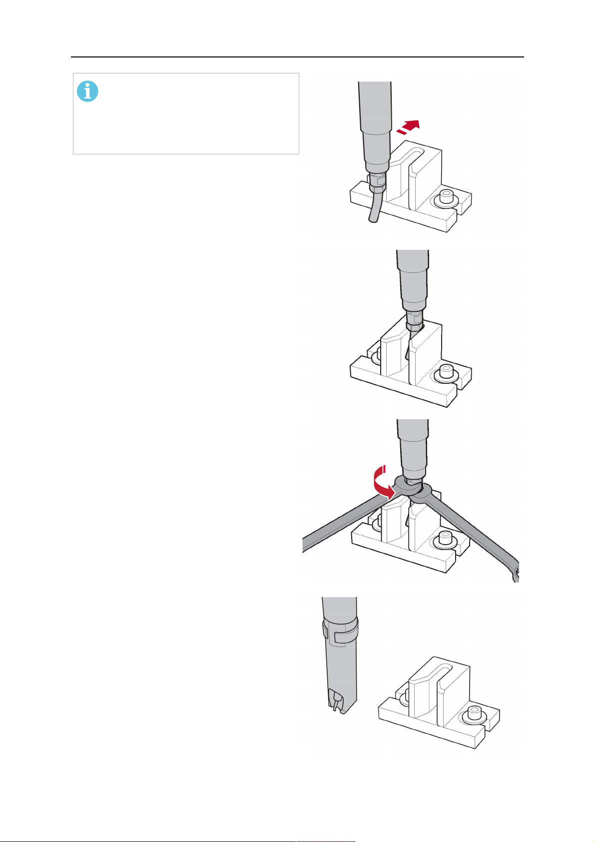
5 INSTALLATION
NOTA:
The contact tip must be able to be
easily moved by hand in both
directions in order to enable the
threading of the adjusting tool.
Place the robot torch or contact tip directly in
front of the opening of the adjusting tool (2)
(stop position 2).
Insert it slowly from the front until it is
completely inserted into the device (stop
position 3).
The contact tip was aligned exactly in the
device during insertion. Now cautiously
tighten the counter nut (4) in this position,
while counter holding the nozzle holder at the
wrench flat.
Slowly move the robot torch out of the
adjusting gauge, return to stop position 1 and
push on the gas nozzle as far as it will go.
Allow the welding wire to run into the contact
tip and bring the robot arm into welding
position.
0463 373 101
- 57 -
© ESAB AB 2018

6 OPERATION
6 OPERATION
ATENÇÃO!
Before starting the system, check the whole installation according to the
manufacturer's instructions and applicable safety regulations.
Check the following to make sure that the system has been installed correctly:
1. Are all parts securely attached (torch, torch mount, flanges, safety-off device, cable
assembly, and wire feeder cabinet)?
2. Are all media hoses connected correctly and protected from damage?
3. Is the EURO central connector or direct connector fastened tightly?
4. Is the cable assembly length correct and suitable for the installation and can the cable
rotate freely? The cable must not be bent sharply. Any risk of the cable getting caught
on another object must be eliminated.
5. Is the control cable of the safety-off circuit connected and functioning? Move torch by
hand to test (RTKSC-2 and RTKS-2 only).
6. Is the torch firmly attached and is it completely equipped?
7. Is the wire guide installed according to the manual?
8. Are all lines and tubes arranged so that they cannot be damaged or bent?
The wire run-in can now be started, either via the wire run-in pushbutton or via the wire run-in
at the feeder.
6.1 Important information for programming (hollow wrist system only)
Fast rotation of axis 6 of the robot will significantly stress the cable assembly. In certain
cases, this can lead to damage or destruction of the cable. In order to maximize the lifetime
of the cable, we strongly suggest respecting the following limitations when programming the
robot.
Position of axis 5 Max. rotational speed of axis 6
0 – 60° 100 % (no limitations)
60° – 80° 300°/sec (approximately 50 % of max. robot speed)
> 80° 120°/sec (approximately 20 % of max. robot speed)
NOTA:
The above values are only indications. For information on the exact rotational speed
limits, refer to the individual robot manual or contact the robot supplier.
To reposition the torch quickly, the robot arm may have to be slightly extended first to achieve
a bending angle of max. 60° of axis 5. In this position, the maximum available rotation speed
of axis 6 can be used.
When using the ESAB Helix cable assembly, the max. rotation of ±270° from the neutral
position must not be exceeded.
0463 373 101
- 58 -
© ESAB AB 2018

6 OPERATION
ATENÇÃO!
While axis 5 is bent more than 60°, the rotational speed of the torch around axis 6
must be limited, see table above.
Otherwise, the cable assembly may be damaged.
0463 373 101
- 59 -
© ESAB AB 2018

7 SERVIÇO E MANUTENÇÃO
7 SERVIÇO E MANUTENÇÃO
AVISO!
Antes de executar a manutenção no sistema, a alimentação principal da instalação
deve ser desligada. Observe as normas de segurança no início deste manual.
Maçaricos ou conjuntos de cabos danificados não devem ser usados! Defeitos
conhecidos devem ser reparados por pessoal qualificado antes do próximo uso do
equipamento.
AVISO!
Risco de queimaduras! O bico de gás e a cabeça do maçarico ficam muito quentes
durante a soldagem. Deixe o maçarico esfriar antes de realizar a manutenção.
AVISO!
Para evitar lesões pessoais ou danos à sua instalação, siga estas instruções:
1. O reparo do suporte do maçarico RTKSC-2 ou RTFLC-2, do mecanismo
de desligamento de segurança do RTKS-2, do conjunto de cabos ou do
acoplamento de mídia do Infiniturn só deve ser realizado pelo suporte de
serviço ESAB.
2. O acoplamento de mídia do Infiniturn nunca deve ser aberto. Ele não
contém peças cuja manutenção possa ser realizada pelo usuário e será
destruído pela desmontagem.
3. Nunca desmonte o RTKSC-2 ou RTKS-2. Este é um mecanismo
acionado por mola. A manipulação inadequada pode levar a lesões
graves.
7.1 Verificações e ações obrigatórias
Antes de cada uso:
• Verifique o maçarico, a ponta de contato, o bico de gás, o revestimento do pescoço, os
cabos e o equipamento como um todo quanto a danos gerais.
NOTA:
Para minimizar o tempo de inatividade, é recomendável alternar entre dois
pescoços de maçarico, sempre tendo um pescoço de maçarico recém-equipado e
pronto para uso.
A cada 8 horas de uso (dependendo da aplicação):
• Troque a ponta de contato.
Diariamente:
• Faça uma verificação manual das funções do mecanismo de desligamento de
segurança.
• Faça uma inspeção visual quanto a danos, por exemplo, dobras ou rachaduras.
• Verifique a posição correta do alimentador de fios. O conjunto de cabos não deve estar
muito tenso ou pendurado.
• Inspecione as conexões de mídia e o acoplamento de mídia do Infiniturn quanto a
vazamentos.
• Faça a limpeza e manutenção do maçarico de acordo com o manual do maçarico.
A cada 40 horas de uso (dependendo da aplicação):
0463 373 101
- 60 -
© ESAB AB 2018

7 SERVIÇO E MANUTENÇÃO
• Troque os revestimentos do fio.
• Troque os revestimentos do pescoço.
Semanalmente ou conforme necessário, dependendo do uso:
• Remova a guia de fio e verifique se há desgaste e sujeira. Troque se necessário.
Mensalmente ou mais frequentemente com uso intenso (ou seja, mais de 8 horas/dia):
• Sopre o canal da guia de fio com ar comprimido (remova a ponta de contato e a guia
do fio).
• Certifique-se de que todos os parafusos estejam apertados.
• Inspecione todas as conexões e mangueiras para ver se há danos.
• Depois, troque todo o fio soldado de 250 kg.
Danos ao isolamento elétrico devem ser reparados por pessoal treinado antes que o sistema
possa ser operado com segurança.
0463 373 101
- 61 -
© ESAB AB 2018

8 SOLUÇÃO DE PROBLEMAS
8 SOLUÇÃO DE PROBLEMAS
Avaria Possível causa Ação
Não é possível
alimentar o fio
O fio de soldagem não foi
endireitado antes de alimentá-lo no
conjunto de cabos
O maçarico e o conjunto de cabos
não estão equipados corretamente
para o diâmetro e material do fio
A guia de fio não está inserida
corretamente no conjunto de cabos
A ponta de contato bloqueada está
obstruída com detritos no fio
A guia de fio está desgastada
A alimentação do fio está obstruída
por sujeira e detritos no maçarico
Se necessário, puxe o fio de
soldagem para fora novamente,
corte e retire as rebarbas da
extremidade e endireite os
primeiros 10 cm do fio. Em seguida,
rosqueie novamente no conjunto de
cabos.
Verifique a guia de fio (conjunto de
cabos e pescoço do maçarico) e a
ponta de contato.
Puxe um pouco a guia de fio do
conector Euro. Ao inserir a guia de
fio, você deve sentir que os últimos
centímetros deslizam no bico da
guia na interface do maçarico. Caso
contrário, a guia de fio pode estar
muito curta e não totalmente
inserida.
Substitua a ponta de contato e/ou a
guia do fio, o pescoço do maçarico
do sopro, o conduíte da guia do fio
e a guia de fio com ar comprimido.
O maçarico está
ficando muito
quente
A ponta de contato ou o suporte de
ponta não estão apertados
Use uma ferramenta adequada
para apertar com as mãos.
corretamente
O sistema de resfriamento não está
funcionando corretamente
O sistema de resfriamento não está
conectado corretamente
Verifique a vazão de água, o nível
de enchimento e a limpeza.
Verifique as conexões (entrada e
retorno de água).
Maçarico sobrecarregado Observe os dados técnicos, se
necessário, escolha um tipo
diferente.
Conjunto de cabos com defeito Verifique cabos, tubos e conexões.
0463 373 101
- 62 -
© ESAB AB 2018

8 SOLUÇÃO DE PROBLEMAS
Avaria Possível causa Ação
Problemas com
a alimentação
do fio
A alimentação
do fio para
durante a
soldagem
A ponta de contato está desgastada Troque a ponta de contato.
O revestimento está gasto/sujo Verifique o revestimento; sopro.
Troque se necessário.
Os consumíveis usados não são
adequados para o diâmetro ou
Verifique a lista de peças
sobressalentes.
material do fio
O alimentador de fios não foi
configurado corretamente
Verifique os cilindros de
alimentação do fio, a pressão de
contato e o freio do carretel.
O conjunto de cabos está dobrado
ou disposto em raios muito
pequenos
Verifique se há danos no conjunto
de cabos. O revestimento pode ser
inserido facilmente? Instale
seguindo as instruções. Consulte a
seção "Instalação do conjunto de
cabos".
O fio está contaminado Use um feltro de limpeza.
O carretel do fio está vazio Verifique a quantidade do fio de
soldagem no carretel no
alimentador de fios.
Bloqueio do fio no conjunto de
cabos
Verifique a alimentação do fio
(possivelmente muito rápida),
verifique se há
contaminação/obstrução na ponta
de contato, limpe ou substitua a
ponta de contato, se necessário.
O processo de
soldagem está
parando
Poros na
costura
O arco não está
estável
O fio queimou na ponta de contato
Substitua a ponta de contato.
ou a ponta de contato está gasta
O mecanismo de desligamento de
segurança foi acionado.
Procure pontos de colisão e
evite-os. Verifique se há contato
solto na linha de controle.
Turbulência de gás causada pela
aderência dos respingos
Limpe a cabeça do maçarico, use o
difusor de gás/proteção contra
respingos.
Vazão de gás muito pequena ou
extremamente alta no maçarico
Verifique a taxa de vazão com a
ferramenta de medição.
Suprimento de gás com defeito Verifique a taxa de vazão e
possíveis vazamentos.
Umidade ou contaminação no fio ou
na peça de trabalho
Verifique o fio e a peça de trabalho,
use menos ou outro líquido
antirespingo.
A ponta de contato está desgastada Troque a ponta de contato.
Parâmetros de solda incorretos Verifique a configuração do
equipamento de soldagem.
Conexões elétricas insuficientes no
circuito
Verifique todas as conexões
elétricas (incluindo o cabo de
aterramento) entre o maçarico da
fonte de alimentação ou a peça de
trabalho para um assento firme.
0463 373 101
- 63 -
© ESAB AB 2018

9 PEDIDOS DE PEÇAS SOBRESSALENTES
9 PEDIDOS DE PEÇAS SOBRESSALENTES
ATENÇÃO!
Reparo e trabalhos de eletricidade devem ser executados por um técnico de serviço
autorizado da ESAB. Use apenas peças sobressalentes e de desgaste originais da
ESAB.
Os maçaricos RT ESABRTKS-2, RTFL-2, RT-KSC-2, RT-FLC-2, RT42, RT52, RT62,
RT72, RT82, RT42-NG e RT82WNG são projetados e testados de acordo com as
normas internacionais e europeias IEC/EN 60974-7. É obrigação da unidade de
manutenção que executou o serviço ou reparo garantir que o produto ainda esteja em
conformidade com o padrão mencionado.
Peças sobressalentes e peças de desgaste podem ser solicitadas por meio de seu
revendedor ESAB mais próximo, consulte esab.com. Ao solicitar, indique tipo de produto,
número de série, emprego e número da peça sobressalente, de acordo com a lista de peças
sobressalentes. Isso facilita o envio e garante a entrega correta.
0463 373 101
- 64 -
© ESAB AB 2018

9 PEDIDOS DE PEÇAS SOBRESSALENTES
0463 373 101
- 65 -
© ESAB AB 2018

ESAB AB, Lindholmsallén 9, Box 8004, 402 77 Gothenburg, Sweden, Phone +46 (0) 31 50 90 00
http://manuals.esab.com
For contact information visit esab.com
 Loading...