


RT Robo Welding Torch System
RTKS-2, RTFL-2, KSC-2, FLC-2, RT42, RT52,
RT62, RT72, RT82, RT42-NG, RT82WNG
Kullanma talimatı
0463 373 101 TR 20181227


İÇINDEKILER
1
GÜVENLİK................................................................................................... 5
1.1 Sembollerin anlamı ................................................................................ 5
1.2 Güvenlik önlemleri ................................................................................. 5
2
GARANTİ ..................................................................................................... 8
2.1 Kullanım koşulları .................................................................................. 8
3
GİRİŞ............................................................................................................ 9
3.1 Kaynak üfleci sistemlerine genel bakış................................................ 10
4
TEKNİK VERİLER ....................................................................................... 12
4.1 Kaynak üfleç muylusu ........................................................................... 12
4.2 Gerilim oranı ........................................................................................... 13
4.2.1 Soğutma devresinin sınırları................................................................. 13
4.3 Üfleç desteği ........................................................................................... 14
4.3.1 Standart RT sistemi için üfleç destekleri............................................... 14
4.3.1.1 RTKS-2 güvenlik amaçlı kapatma mekanizması.............................. 15
4.3.1.2 RTFL-2 ara flanşı.............................................................................. 15
4.3.2 İçi boş bilek sistemi için üfleç destekleri ............................................... 15
4.3.2.1 Güvenlik amaçlı kapatma mekanizmalı RTKSC-2 G/W üfleç
desteği...............................................................................................
4.3.2.2 RTFLC-2 G/W rijit üfleç desteği........................................................ 18
4.4 Adaptör flanşları ..................................................................................... 19
4.5 Kablo grupları ......................................................................................... 19
4.5.1 Standart RT sistemi için kablo grupları................................................. 19
4.5.2 İçi boş bilek sistemleri için kablo grupları ............................................. 20
5
INSTALLATION............................................................................................ 22
5.1 RTKS-2 standard arm installation........................................................ 22
5.1.1 RTKS-2 safety-off mechanism............................................................. 22
5.1.1.1 Torch installation with adjustable mount............................................ 23
5.1.2 Standard arm cable assembly for KS-2 and FL-2 ................................ 25
5.1.3 RTKS-2 wire feeder connection........................................................... 26
5.1.4 RTKS-2 electrical connections ............................................................ 27
5.1.4.1 RTKS-2 safety-off mechanism connection ....................................... 27
5.1.5 RTKS-2 Torch installation .................................................................... 28
5.2 RTFL-2 standard arm installation ........................................................ 29
17
5.2.1 RTFL-2 rigid mount.............................................................................. 29
5.2.2 RTFL-2 torch installation ..................................................................... 31
5.3 RTKSC-2 hollow wrist system installation.......................................... 31
5.3.1 RTKSC-2 mount with safety off mechanism........................................ 31
5.3.2 Mounting the cable assembly............................................................... 32
5.3.2.1 RTKSC-2 feeder cabinet connections .............................................. 33
5.3.3 RTKSC-2 cable assembly ................................................................... 35
5.3.3.1 RTKSC-2 cable assembly installation .............................................. 35
0463 373 101 © ESAB AB 2018

İÇINDEKILER
5.3.3.2 RTKSC-2 electrical connections....................................................... 38
5.3.4 RTKSC-2 torch installation .................................................................. 39
5.4 RTFLC-2 installation.............................................................................. 40
5.4.1 RTFLC-2 mount................................................................................... 40
5.4.2 RTFLC-2 wire feeder connection......................................................... 40
5.4.2.1 Feeding through the robot arm.......................................................... 40
5.4.2.2 RTFLC-2 feeder cabinet connections............................................... 41
5.4.3 RTFLC-2 cable assembly .................................................................... 43
5.4.3.1 RTFLC-2 cable assembly installation............................................... 43
5.4.4 RTFLC-2 electrical connections .......................................................... 46
5.4.4.1 RTFLC-2 hollow wrist system with Infiniturn cable assembly........... 46
5.4.4.2 RTFLC-2 hollow wrist system with Helix cable assembly................. 47
5.5 Torch installation.................................................................................... 47
5.5.1 Torch neck equipment .......................................................................... 47
5.5.2 Aristo RT torch neck installation ........................................................... 48
5.6 Installing the wire guide for standard and hollow Wrist arm ............. 49
5.6.1 Installing the neck liner......................................................................... 49
5.6.2 Installing a split wire guide in the cable assembly................................ 50
5.6.3 Installing a continuous wire guide in the cable assembly..................... 52
5.7 Adjust the narrow gap contact tip ........................................................ 53
6
OPERATION ................................................................................................ 56
6.1 Important information for programming (hollow wrist system only) 56
7
SERVİS VE BAKIM...................................................................................... 58
7.1 Zorunlu kontrol ve işlemler ................................................................... 58
8
SORUN GİDERME....................................................................................... 60
9
YEDEK PARÇA SİPARİŞİ ........................................................................... 62
Özellikleri haber vermeksizin değiştirme hakları saklıdır.
0463 373 101 © ESAB AB 2018

1 GÜVENLİK
1 GÜVENLİK
1.1 Sembollerin anlamı
Bu kılavuz boyunca kullanıldığı gibi: Dikkatli Olun! Uyanık olun!
TEHLİKE!
Ani tehlike anlamına gelir. Önlenmediği takdirde ani, ciddi yaralanmalara
veya can kaybına neden olur.
UYARI!
Potansiyel tehlike anlamına gelir; yaralamalara veya can kaybına neden
olabilir.
DİKKAT!
Küçük çaplı bedensel yaralanmalara sebep olabilecek tehlike anlamına gelir.
UYARI!
Kullanımdan önce kullanım kılavuzunu okuyun ve
anlayın; tüm etiketlere, işveren güvenlik uygulamalarına
ve Güvenlik Veri Formlarına (SDS'ler) uyun.
1.2 Güvenlik önlemleri
ESAB cihazının kullanıcıları cihaz ile veya cihaza yakın çalışan herkesin ilgili tüm güvenlik
önlemlerine uymasını sağlamak için nihai sorumluluğu taşımalıdır. Güvenlik önlemleri bu tip
cihazlar için geçerli gereksinimleri karşılamalıdır. İşyeri için geçerli standart yönetmeliklere ek
olarak aşağıdaki tavsiyelere uyulmalıdır.
Tüm çalışmalar eğitimli, cihazın çalışmasına aşina personel tarafından yapılmalıdır. Cihazın
hatalı çalıştırılması operatörün yaralanmasına ve cihazın zarar görmesine neden olabilecek
tehlikeli durumlara yol açabilir.
1. Cihazı kullanan herkesin aşağıdakilere aşina olması gerekir:
○ çalışmasına
○ acil durdurma yerlerine
○ fonksiyonuna
○ ilgili güvenlik önlemlerine
○ cihazın kaynak yapma ve kesme veya ilgili diğer işlemleri
2. Operatör aşağıdakileri sağlamalıdır:
○ çalışmaya başlandığında cihazın çalışma alanı içinde hiçbir yetkisiz kişinin
bulunmaması.
○ ark vurduğunda veya cihazla çalışmaya başlandığında hiç kimsenin korumasız
olmaması
3. İşyeri şu özelliklerde olmalıdır:
○ amaca uygun
○ hava akımından etkilenmeyen
0463 373 101
- 5 -
© ESAB AB 2018

1 GÜVENLİK
4. Kişisel güvenlik ekipmanı:
○ Daima, örneğin koruyucu gözlük, alev geçirmez giysi, koruyucu eldiven gibi,
önerilen kişisel güvenlik ekipmanlarını giyin.
○ Sıkışabilecek veya yanıklara neden olabilecek bol elbiseler, örneğin eşarp,
bilezik, yüzük, vb., takmayın.
5. Genel önlemler:
○ Dönüş kablosunun sağlam şekilde bağlandığından emin olun.
○ Yüksek gerilim cihazları ile ilgili çalışmalar sadece yetkili bir elektrikçi
tarafından gerçekleştirilebilir
○ Uygun yangın söndürme ekipmanı açıkça işaretlenmiş ve elinizin altında
olmalıdır.
○ Cihazın yağlama ve bakım işlemi cihaz çalışırken yapılmamalıdır
UYARI!
Ark kaynak ve kesme kendinize ve başkalarına zararlı olabilir. Kaynak ve kesme
sırasında önlemler alın.
ELEKTRİK ÇARPMASI - Öldürebilir
• Üniteyi kullanım kılavuzuna uygun şekilde takın ve topraklayın.
• Çıplak tenle, ıslak eldivenle veya ıslak giysilerle üzerinde elektrik bulunan
parçalara veya elektrotlara dokunmayın.
• Kendinizi işten ve topraktan izole edin.
• Çalışma konumunuzun güvenli olduğundan emin olun
ELEKTRİKLİ VE MANYETİK ALANLAR - Sağlık için tehlikeli olabilir
• Kalp pili olan kaynakçılar, kaynak işinden önce doktorlarına danışmalıdır.
EMF, bazı kalp pillerinde parazit yapabilir.
• EMF'ye maruz kalmanın, sağlık üzerinde bilinmeyen diğer etkileri olabilir.
• Kaynakçılar, EMF maruziyeti etkilerini en aza indirmek için aşağıdaki
prosedürleri kullanmalıdır:
○ Elektrodu ve çalışma kablolarını vücudunuzla aynı tarafta olacak
şekilde birlikte yönlendirin. Mümkünse bunları bantla sabitleyin.
Şaluma ve iş kabloları arasında durmayın. Şalumayı veya iş
kablosunu asla vücudunuza dolamayın. Kaynaklama güç kaynağını
ve kabloları vücudunuzdan olabildiğince uzakta tutun.
○ İş kablosunu, iş parçasına kaynak yapılan alana mümkün olduğunca
yakın şekilde bağlayın.
DUMAN VE GAZLAR - sağlık için tehlikeli olabilir
• Başınızı dumandan uzak tutun.
• Gazları ve dumanları nefes aldığınız yerden veya genel olarak bölgeden
çıkarmak için havalandırmayı, arkta dışa atımı veya ikisini birden kullanın.
ARK IŞINLARI - gözlerinize zarar verebilir ve cildi yakabilir
• Gözlerinizi ve bedeninizi koruyun. Doğru kaynak paravanını ve filtre
merceğini kullanın ve koruyucu giysiler giyin.
• Yakındakileri uygun paravanlar veya perdelerle koruyun.
0463 373 101
GÜRÜLTÜ - Aşırı gürültü işitmeye zarar verebilir
Kulaklarınızı koruyun. Kulak tıkaçları veya diğer işitme korumalarını kullanın.
- 6 -
© ESAB AB 2018

1 GÜVENLİK
HAREKETLİ PARÇALAR - Yaralanmaya neden olabilir
• Tüm kapıların, panellerin ve kapakların kapalı ve emniyetli bir şekilde
yerinde olduğundan emin olun. Gerektiğinde, yalnızca yetkili kişilerin
kapakları bakım ve sorun giderme işlemleri için çıkarmasını sağlayın.
Servis işlemi bittiğinde, motoru çalıştırmadan önce panelleri veya kapakları
yeniden takın ve kapıları kapatın.
• Üniteyi takmadan veya bağlamadan önce motoru durdurun.
• Ellerinizi, saçınızı, bol giysileri ve aletleri hareketli parçalardan uzak tutun.
YANGIN TEHLİKESİ
• Kıvılcımlar (sıçrayan alevler) yangına neden olabilir. Yakında tutuşabilen
malzemeler olmadığından emin olun.
• Kapalı konteynerlerde kullanmayın.
ARIZA - arıza durumunda uzmanından yardım isteyiniz.
KENDİNİZİ VE DİĞERLERİNİ KORUYUN!
DİKKAT!
Bu ürün sadece ark kaynağı için tasarlanmıştır.
UYARI!
Donmuş boruların erimesi için güç kaynağı kullanmayın.
DİKKAT!
A sınıfı ekipman, düşük voltajlı elektrik besleme sistemi
tarafından elektrik sağlanan konut mahallerinde
kullanılmak üzere tasarlanmamıştır. Sebebiyet verilen
ve aynı zamanda yayılan bozukluklar nedeniyle, bu
yerlerde A sınıfı ekipmanın elektromanyetik uyumluluk
sağlanmasında olası güçlükler söz konusu olabilir.
NOT!
Elektronik cihazları bir geri dönüşüm tesisinde imha
edin!
Atık Elektrikli ve Elektronik Cihazlar Avrupa Direktifi'ne
2012/19/EC ve ulusal hukuka uygun olarak
uygulanmasına riayet edilerek, kullanım ömrünün
sonuna gelen elektrikli ve/veya elektronik cihazların geri
dönüşüm tesisinde bertaraf edilmesi gerekmektedir.
Ekipmanın sorumlu kişisi olarak, onaylanmış toplama
istasyonları hakkında bilgi elde etmek sizin
sorumluluğunuzdadır.
Detaylı bilgi için en yakın ESAB bayisine başvurun.
ESAB, çeşitli kaynak aksesuarları ve kişisel koruyucu ekipmanları satışa sunmaktadır.
Sipariş bilgileri için yerel ESAB bayinizle iletişime geçin veya web sitemizi ziyaret
edin.
0463 373 101
- 7 -
© ESAB AB 2018

2 GARANTİ
2 GARANTİ
Ürünlerimiz, teslimattan önce dikkatli bir şekilde kontrol edilmektedir. ESAB, hiçbir üründe
teslimat sırasında malzeme ve işçilik kusuru olmadığını ve kullanım amacına uygun olarak
çalıştığını onaylar.
ESAB, malzeme ve işçilik kusurları konusunda yasal gerekliliklere uygun olarak garanti
vermektedir. Sarf malzemeleri, bu garanti kapsamının dışındadır.
Garanti, aşağıdakilerden kaynaklanan hasar veya işlev kusurlarını kapsamaz:
• aşırı yükleme, kötüye kullanım veya ürünü kullanım amacından saptırma,
• çarpışma veya kazalar,
• bu kullanım talimatlarında belirtilen talimatlara uymama,
• uygunsuz kurulum veya montaj,
• yetersiz bakım,
• ürünü orijinal halinden değiştirme,
• kimyasal etkiler ile
• normal yıpranma ve aşınma
ESAB, arızalı parçaların değişimi veya onarımı dışında hiçbir sorumluluk kabul etmez.
2.1 Kullanım koşulları
1. Ürün, endüstriyel ve ticari kullanım için tasarlanmıştır ve sadece eğitimli personel
tarafından kullanılmalıdır. Üretici, uygunsuz kullanımdan kaynaklanan hasar veya
kazalardan sorumlu değildir.
2. Aristo® RT Robotik Kaynak Sistemi, en yeni teknolojiler ile tasarlanıp üretilmiştir ve
eğitimli personel tarafından kullanırken, kurulurken ve bakımı yapılırken emniyetli ve
güvenilir bir şekilde çalışır. Bu belgedeki kurulum, çalıştırma ve bakım talimatlarına
uyulmalıdır.
3. Aristo® RT Robotik Kaynak Sistemi yalnızca eğitimli personel tarafından kurulmalı,
çalıştırılmalı ve bakımı yapılmalıdır. Bu kılavuzda açıklanan montaj, çalıştırma ve
bakım kurallarına uyulmalıdır.
4. Aristo® RT Robotik Kaynak Sistemi yalnızca üretici tarafından teknik verilerde
belirtilen kullanım amacına uygun olarak ve otomatik taşıma sistemleriyle kullanılabilir.
Üfleç tipi, kaynak işine uygun olarak seçilmelidir.
5. Aristo® RT Robotik Kaynak Sistemi, eksiksiz bir sistem olarak kullanılmak üzere
tasarlanmıştır. Başka üreticiler tarafından üretilmiş bileşenlerin sisteme eklenmesine
izin verilmez.
6. RT KS-2 ve RT KSC-2 yalnızca teknik özellikleri kapsamında acil durdurma
mekanizmaları olarak ve RT standart kol kablo grubu (KS-2), Infiniturn veya Helix
(KSC-2), ESAB adaptör flanşı ve RT üfleç bağlantıları (KS-2) ve Aristo RT kaynak
üfleci ile birlikte kullanılmalıdır.
7. Atılan gaza yağ veya sıçrama önleyici sıvı eklenmemelidir. ESAB bu maddelere karşı
kimyasal direnç olacağının garantisini vermez. ESAB, üflece en az miktarda sıçrama
önleyici sıvı uygulamak için ESAB püskürtme ünitesinin kullanılmasını ve böylece
çevrenin korunmasını önerir.
8. Ürün, kuru bir yerde muhafaza edilmeli ve taşınırken, depolanırken veya kullanılırken
nemden korunmalıdır.
9. Sistem, 5° ile 40°C (41 ile 104°F) arasındaki ortam sıcaklıkları için tasarlanmıştır. Bu
limitlerin aşılması durumunda özel işlem uygulanması gerekir. Donma riski durumunda
uygun bir soğutma suyu kullanın.
0463 373 101
- 8 -
© ESAB AB 2018

3 GİRİŞ
3 GİRİŞ
RT kaynak üfleci sistemleri, robot kullanarak yapılan tam otomatik MIG/MAG kaynak işlemleri
için geliştirilmiştir. Sistemler robotik kullanım amacıyla tasarlanmış çeşitli Aristo RT üfleç
muyluları, üfleç destekleri, robotik kullanım için optimize edilmiş kablo grupları ve çarpışma
durumunda sistemin hasar görmesini engelleyen güvenlik amaçlı kapatma özelliklerinden
oluşur.
Standart RT kaynak sistemi, mekanik yay yüklemeli bir güvenlik amaçlı kapatma işlevi olan
RTKS-2'yi kullanarak çarpışmaya karşı koruma sağlar. İsteğe bağlı olarak bunun yerine
RTFL-2 kullanılabilir ve robot kontrol sisteminin çarpışma algılama işlevinden yararlanılabilir.
Standart RT kaynak sistemi, çeşitli kablo grubu tipleri ile birlikte kullanılabilir.
Infiniturn veya Helix kablo grupları olan RTKSC-2 ve RTFLC-2 üfleç destekleri, gelişmiş
kaynak uygulamaları için tasarlanmış içi boş bilekli robot kaynak sistemleri ile birlikte
kullanıma yönelik geliştirilmiştir. RTKSC-2 üfleç desteğindeki güvenlik amaçlı kapatma
özelliği, çarpışma durumunda üflecin büyük miktarda elastik olarak şekilde değiştirebilmesini
sağlar. Infiniturn ve Helix kablo grupları kolayca takılabilir, hassas manevra imkanı veren, son
derece güvenilir bir sistem sağlarlar.
Bu sistemler, başarısıyla tanınmış olan Aristo RT robot kaynak üfleçleri ile birlikte en az
miktarda bakım gerektiren, son derece güvenilir ve uzun ömürlü bir sistem sağlar.
Üfleç destekleri ve kablo grupları temin edildiğinde, kullanım kılavuzu da verilir.
ESAB sipariş numaraları, mevcut aksesuarlar, yedek parçalar ve aşınan parçalar,
yedek parça listesinde bulunabilir.
0463 373 101
- 9 -
© ESAB AB 2018

3 GİRİŞ
3.1 Kaynak üfleci sistemlerine genel bakış
Standart RT sistemi
Ayrıntılı bir açıklama için TEKNİK VERİLER
bölümündeki ilgili bölüme bakın:
1. Üfleç muylusu
"Kaynak üfleci" bölümüne bakın.
2. Kablo grubu
"Standart RT sistemi için kablo
grupları" bölümüne bakın.
3. Üfleç desteği
"Standart RT sistemi için üfleç
destekleri" bölümüne bakın.
4. RTKS-2 güvenlik amaçlı kapatma
mekanizması
"RTKS-2 güvenlik amaçlı kapatma
mekanizması" bölümüne bakın.
5. RTFL-2 ara flanşı
"RTFL-2 ara flanşı" bölümüne
bakın.
6. Adaptör flanşı (gerekirse)
"Adaptör flanşları" bölümüne bakın.
0463 373 101
- 10 -
© ESAB AB 2018

3 GİRİŞ
İçi boş bilek sistemi
Ayrıntılı bir açıklama için TEKNİK VERİLER
bölümündeki ilgili bölüme bakın:
1. Üfleç muylusu
"Kaynak üfleci" bölümüne bakın.
2. Üfleç desteği RTKSC-2
"RTKSC-2 güvenlik amaçlı kapatma
mekanizmalı üfleç desteği"
bölümüne bakın.
3. Üfleç desteği RTFLC-2
"RTFLC-2 rijit üfleç desteği"
bölümüne bakın.
4. Adaptör flanşı
"Adaptör flanşları" bölümüne bakın.
5. Helix veya Infiniturn kablo grubu
Bkz. "İçi boş bilek sistemleri için
kablo grupları".
0463 373 101
- 11 -
© ESAB AB 2018

4 TEKNİK VERİLER
4 TEKNİK VERİLER
4.1 Kaynak üfleç muylusu
Üfleç modelini kaynak uygulamasına uygun şekilde seçin. Gereken görev döngüsü ve
kapasite, soğutma yöntemi ve kablo çapı göz önünde bulundurulmalıdır. Önceden ısıtılmış iş
parçaları veya köşelerde yüksek ısı yansıması gibi gereksinimlerin artması durumunda,
yeterince yedek güce sahip bir kaynak üfleci seçerek bunlar göz önünde bulundurulmalıdır.
RT kaynak üfleçleri ticari yuvarlak tellerle gerçekleştirilen Metal Asal Gaz kaynağı (MIG),
Metal Aktif Gaz kaynağı (MAG) ve Metal Asal Gaz Lehimi işlemlerinin CE uyumlu kaynak güç
üniteleriyle kullanılmak üzere tasarlanmıştır. Üfleci diğer işlemlerde kullanmayın.
Çelik veya alüminyumda darbeli ark kaynağı için RT82W su soğutmalı üfleçler
kullanılmalıdır.
Aşağıda mevcut üfleç modellerini görebilirsiniz.
Üfleç modeli Soğutma yöntemi Koruyucu gaz Değerler
RT42G Gaz soğutmalı CO
Gaz soğutmalı 300A / %100
Gaz soğutmalı Karışım 350A / %60
Gaz soğutmalı 250A / %100
RT42W Su soğutmalı CO
Su soğutmalı 420A / %100
Su soğutmalı Karışım 350A / %60
Su soğutmalı 350A / %100
RT52G Gaz soğutmalı CO
Gaz soğutmalı 300A / %100
Gaz soğutmalı Karışım 350A / %60
Gaz soğutmalı 250A / %100
RT52W Su soğutmalı CO
Su soğutmalı 470A / %100
Su soğutmalı Karışım 400A / %60
Su soğutmalı 400A / %100
RT62G Gaz soğutmalı CO
Gaz soğutmalı 340A / %100
2
2
2
2
2
420A / %60
420A / %60
420A / %60
470A / %60
500A / %60
Gaz soğutmalı Karışım 420A / %60
Gaz soğutmalı 290A / %100
RT62W Su soğutmalı CO
Su soğutmalı 530A / %100
Su soğutmalı Karışım 450A / %60
Su soğutmalı 450A / %100
RT72G Gaz soğutmalı CO
Gaz soğutmalı 320A / %100
Gaz soğutmalı Karışım 400A / %60
Gaz soğutmalı 270A / %100
0463 373 101
- 12 -
2
2
530A / %60
480A / %60
© ESAB AB 2018

4 TEKNİK VERİLER
Üfleç modeli Soğutma yöntemi Koruyucu gaz Değerler
RT72W Su soğutmalı CO
2
480A / %60
Su soğutmalı 430A / %100
Su soğutmalı Karışım 480A / %60
Su soğutmalı 430A / %100
RT82W Su soğutmalı CO
2
600A / %60
Su soğutmalı 600A / %100
Su soğutmalı Karışım 550A / %60
Su soğutmalı 550A / %100
Üfleç değeri ve görev döngüsü değerleri, 10 dakikalık döngü için geçerlidir.
Teknik veriler, standart aşınan/yedek parçaların kullanıldığı standart bir uygulama için
geçerlidir. Üfleç değeri, darbeli ark metal aktarma modunu kullanırken düşer.
Sıcaklık aralıkları Depolama: -15-50°C (5-122°F)
Çalışma: 5–40°C (41–104°F)
Atılan gaz Maksimum 10 bar, ayrı gaz hortumu
Toplam ağırlık (üfleç muylusu, güvenlik
Yaklaşık 5 kg
amaçlı kapatma mekanizması, üfleç desteği
ve 1 m kablo grubu)
4.2 Gerilim oranı
İzin verilen maks. voltaj/akım
Tüm kaynak üfleci sistemi 141 V (kaynak için en yüksek değer)
RTKS-2 güvenlik amaçlı kapatma kontrol
devresi
RTKS-2 basmalı düğmesi
RT KSC-2 güvenlik amaçlı kapatma kontrol
devresi
Standart kablo grubu ile nozül algılama
işlevinin kullanımı
Helix veya Infiniturn kablo grupları ile nozül
algılama işlevinin kullanımı
Belirtilen oranlar, standart kullanım durumunu ifade eder.
Kablo grubu değerleri için "Kablo grupları" bölümüne bakın.
24 V / 1 A
48 V / 0,1 A
48 V
50 V / 5 A
(İzin verilen yük, anma nominal akımda
maks. 1 dakika)
50 V / 5 A
(İzin verilen yük, anma nominal akımda
maks. 1 dakika)
4.2.1 Soğutma devresinin sınırları
Yalnızca su soğutmalı model için geçerlidir.
Minimum su debisi: 1,0 l/dak (1,1 kuart/dak)
Minimum su basıncı: 2,5 bar (36,3 PSI)
Maksimum su basıncı: 3,5 bar (50,8 PSI)
0463 373 101
- 13 -
© ESAB AB 2018

4 TEKNİK VERİLER
Giriş sıcaklığı: Maksimum 40°C (104°F)
Dönüş sıcaklığı: Maksimum 60°C (140°F)
Soğutma kapasitesi: Minimum 1000 W, uygulamaya göre değişebilir
DİKKAT!
60°C (140°F) üzerindeki dönüş sıcaklıkları, kablo grubunun zarar görmesine veya
tahrip olmasına neden olabilir.
4.3 Üfleç desteği
Gereken üfleç desteği tipi, RT kaynak üfleci sisteminin tasarımına ve güvenlik amaçlı
kapatma cihazı seçimine bağlıdır. "Kaynak üfleci sistemlerine genel bakış" bölümüne bakın.
Bileşen Yaklaşık ağırlık
Üfleç desteği (standart sistem için) 0,43 kg
RTKS-2 güvenlik amaçlı kapatma
0,85 kg
mekanizması (standart sistem için)
RTFL-2 ara flanşı (standart sistem için) 0,35 kg
RTKSC-2 üfleç desteği (içi boş bilek sistemi
1,90 kg
için)
RTFLC-2 rijit üfleç desteği (içi boş bilek
1,22 kg
sistemi için)
Robot kaynak üfleci 0,66 kg
4.3.1 Standart RT sistemi için üfleç destekleri
Standart RT sistemlerinde, üfleç RTKS-2 güvenlik amaçlı kapatma mekanizmasına takılır
(veya RTFL-2 ara flanşına), kablo grubu ve bağlanan üfleç muylusu sıkıştırılır.
Üfleç desteğini üfleç tipine ve geometrisine uygun olarak seçin. Çeşitli destek tipleri
kullanılabilir. Standart RT sistemi için mevcut üfleç desteklerini yedek parça listesinde
bulabilirsiniz.
Standart kollu robotlar için üfleç desteği
0463 373 101
- 14 -
© ESAB AB 2018

4 TEKNİK VERİLER
4.3.1.1 RTKS-2 güvenlik amaçlı kapatma mekanizması
RTKS-2 güvenlik amaçlı kapatma mekanizması, çarpışma durumunda robot ve üfleç
sistemini koruyan, yay destekli bir cihazdır.
NOT!
RTKS-2'yi parçalarına ayırmayın.
4.3.1.2 RTFL-2 ara flanşı
Robotun elektronik çarpışma algılama sistemi varsa RTKS-2 yerine RTFL-2 rijit ara flanş
kullanılabilir.
4.3.2 İçi boş bilek sistemi için üfleç destekleri
İçi boş bilek sisteminde, Aristo RT kaynak üfleç muyluları üfleç desteği KSC-2 veya FLC-2'ye
bağlanır.
Üfleç desteği RTKSC-2, çarpışma durumunda üflecin elastik bir şekilde deforme olabilmesini
sağlar. Aynı zamanda bir elektrik kontağı açılır ve robot kontrol sistemine durdurma sinyali
gönderilir. Hatayı sıfırladıktan sonra, üflecin ilk geometrisi ve Alet Orta Noktasına (TCP)
yüksek bir hassasiyet ile ulaşılır. Sistem tamamen mekanik olarak çalışır ve yay yüklemelidir.
Üfleç desteği RTFLC-2'de entegre bir güvenlik amaçlı kapatma işlevi yoktur.
0463 373 101
- 15 -
© ESAB AB 2018

4 TEKNİK VERİLER
İçi boş bilek sistemleri için RTKSC-2 G/W (veya RTFLC-2 G/W) önerilir. Bu üfleç desteği,
Aristo RT serisi gaz soğutmalı ve su soğutmalı üfleçler ile birlikte kullanılabilir.
RTKSC-2 G/W RTFLC-2 G/W
Güvenlik amaçlı kapatma
Mekanik Geçerli değil (rijit bağlantı)
mekanizmasının çalışma
ilkesi
Eksenel serbest bırakma
650 N Geçerli değil (rijit bağlantı)
kuvveti (Fz)
Enlemesine eksendeki
24 Nm Geçerli değil (rijit bağlantı)
serbest bırakma torku (Mx)
Serbest bıraktıktan sonra
Otomatik Geçerli değil (rijit bağlantı)
sıfırlayın
Tekrarlanabilme Standart bir Aristo RT üflecin
TCP noktasında ± 0,1 mm
yanal
Geçerli değil (rijit bağlantı)
Maksimum sapma Yaklaşık ± 8° Geçerli değil (rijit bağlantı)
Güvenlik anahtarı Normalde kapalı
Geçerli değil (rijit bağlantı)
Maksimum elektrik yükü 48 V
/ 1 A
0463 373 101
- 16 -
© ESAB AB 2018

4 TEKNİK VERİLER
Nozül algılama işlevinin
elektrik kontrol devresi
Değerler:
• Helix kablo grupları için:
maks. 50 V DC / 5 A,
maks. 1 dakika
Temas durumunu
algıladıktan sonra
hemen algılama voltajı
bağlantısını kesin.
• Infiniturn kablo
gruplarında, nozül
algılama işlevinin
işlevleri
sınırlandırılmıştır.
Uygulamanızda
kullanılabilecek
çözümlerin ayrıntılı
olarak incelenmesi için
ESAB'ye ulaşın.
Gerilim oranı Güvenlik amaçlı kapatma
kontrol devresi için izin verilen
maksimum voltaj: 48 V.
Değerler:
• Helix kablo grupları için:
maks. 50 V DC / 5 A,
maks. 1 dakika
• Infiniturn kablo grupları
için: maks. 50 V DC / 1
A, maks. 1 dakika
Temas durumunu algıladıktan
sonra hemen algılama voltajı
bağlantısını kesin.
4.3.2.1 Güvenlik amaçlı kapatma mekanizmalı RTKSC-2 G/W üfleç desteği
MaddeAçıklama Fonksiyon
1 Üfleç muylusu desteği Aristo RT üfleç arabirimi
2 RTKSC-2 kapağı Kablo ve üfleç arabirimleri olan grup
0463 373 101
- 17 -
© ESAB AB 2018

4 TEKNİK VERİLER
MaddeAçıklama Fonksiyon
3 Lastik körük Güvenlik amaçlı kapatma mekanizmasının koruması
4 RTKSC-2 ana gövdesi Çarpışma sırasında mekanik olarak şekil
değiştirmeye olanak sağlar
5 Adaptör flanşı Robot bileği ayırma arabirimi (ilgili robota uymalıdır)
6 İndeks pimi Adaptör flanşı ile hassas bir şekilde hizalamak için
7 Kontrol kablosu konnektörü Çarpışma sinyali ve nozül algılama işlevi için elektrik
bağlantısı
8 Mikro anahtar Çarpışma algılama sensörü
4.3.2.2 RTFLC-2 G/W rijit üfleç desteği
MaddeAçıklama Fonksiyon
1 Üfleç muylusu desteği Aristo RT üfleç arabirimi
2 RTFLC-2 kapağı Kablo ve üfleç arabirimleri olan grup
3 RTFLC-2 ana gövdesi Çarpışma sırasında mekanik olarak şekil
değiştirmeye olanak sağlar
4 İndeks pimi Adaptör flanşı ile hassas bir şekilde hizalamak için
5 Adaptör flanşı Robot bileği ayırma arabirimi (ilgili robota uymalıdır)
6 Kontrol kablosu konnektörü (3
Nozül algılama işlevi için elektrik bağlantısı (varsa)
kutuplu)
0463 373 101
- 18 -
© ESAB AB 2018

4 TEKNİK VERİLER
4.4 Adaptör flanşları
Robot tipine bağlı olarak robot koluna bağlantı için gereken adaptör flanşını seçin. Tüm
uygun standart ve içi boş bilek sistemleri için adaptör flanşları bulunmaktadır, yedek parça
listesine bakabilirsiniz.
4.5 Kablo grupları
Tel besleyiciye giden bağlantı kablo grubundan etkilenir. Mevcut modeller büyük oranda
sistem tasarımı ve soğutma maddesine (gaz veya su) bağlı olarak değişir. Yedek parça
listesine bakabilirsiniz.
Değerler 1 m ile 5 m arasındaki kablo uzunlukları için geçerlidir.
Standart kablo
Infiniturn Helix
grubu
Değer (10 dakikalık
döngü)
Gaz soğutmalı
(karışık gaz)
Değer (10 dakikalık
döngü)
Maksimum 500 A /
%60 görev döngüsü
Maksimum 350 A /
%100 görev döngüsü
Maksimum 600 A /
%100 görev döngüsü
Maksimum 400 A /
%60 görev döngüsü
Maksimum 320 A /
%100 görev döngüsü
Maksimum 550 A /
%100 görev döngüsü
Su soğutmalı
Dönüş aralığı Sınırlı dönüş kabiliyeti Sınırsız döndürme
kabiliyeti
Ağırlık
Gaz soğutmalı
Ağırlık
Su soğutmalı
1,2 m uzunluk:
2,35 kg
1,2 m uzunluk:
2,35 kg
1,0 m uzunluk:
2,0 kg
1,0 m uzunluk:
2,0 kg
4.5.1 Standart RT sistemi için kablo grupları
Maksimum 400 A /
%60 görev döngüsü
Maksimum 320 A /
%100 görev döngüsü
Maksimum 550 A /
%100 görev döngüsü
Ana konumdan
itibaren ± 270°
1,0 m uzunluk:
2,0 kg
1,0 m uzunluk:
2,0 kg
0463 373 101
- 19 -
© ESAB AB 2018

4 TEKNİK VERİLER
Burndy konnektör pimleri
A. Dokunmayı Algılayan Gaz
Nozülü
C. Çarpışma sensörü
F. 0V
G. + Motor voltajı
H. - Motor voltajı
D. Çarpışma sensörü
E. Yavaş hareket
MaddeAçıklama Fonksiyon
1 Muylu destek flanşı Üfleç arabirimi
2 Koruyucu kapak Kablo grubunu hasara karşı korur
3 Burndy konnektör, 12 kutuplu Güvenlik amaçlı kapatma mekanizması ile tel
besleyici arasındaki elektrik bağlantısı
4 Kontrol kablosu KS-2 için (güvenlik amaçlı kapatma ve basmalı
düğme)
5 EURO konnektör Kablo besleyici bağlantısı
6 Üfleme hortumu (siyah kapaklı) Temizleme döngüsünden sonra üfleci basınçlı
havayla temizlemek için
7 Su girişi (mavi kapak)
8 Su dönüşü (kırmızı kapak)
Üfleç soğutma için su girişi
Isınan suyun üfleçten dönüşü
1)
1)
9 Güvenlik amaçlı kapatma
mekanizması için kontrol
Güvenlik amaçlı kapatma sinyali ve nozül algılama
işlevi için RTKS-2 ile elektrik bağlantısı
kablosu soketi
1)
Yalnızca su soğutmalı üfleç sistemleri
4.5.2 İçi boş bilek sistemleri için kablo grupları
Infiniturn kablo grubu, üflecin her iki yönde sınırsız şekilde döndürülebilmesini sağlar. Aynı
zamanda soğutma sıvısı, koruyucu gaz, atılan hava, kaynak gücü ve güvenlik amaçlı
kapatma mekanizmasının sinyali de aktarılır.
Helix kablo grubu, ana konumdan maksimum ±270° dönüş yapacak şekilde tasarlanmıştır.
Sınırsız döndürmeyi gerektirmeyen kaynak işlemlerinde kullanılabilir.
Infiniturn kablo gruplarının gaz ve su soğutmalı modelleri vardır. Helix kablo grupları, tüm gaz
veya su soğutmalı uygulamalarda kullanılabilir.
NOT!
Gaz soğutmalı üfleç muylusu ile çalışan bir Helix kablo grubunu su soğutmalı bir
sisteme bağlamayın.
0463 373 101
- 20 -
© ESAB AB 2018

4 TEKNİK VERİLER
MaddeAçıklama Fonksiyon
1 Flanş Üfleç desteği RTKSC-2 / RTFLC-2 arabirimi
2 İndeks pimi Bağlantı yönünün doğru olmasını sağlar
3 Kontrol kablosu soketi Güvenlik amaçlı kapatma sinyali ve nozül algılama
işlevi için RTKS-2 ile elektrik bağlantısı (varsa)
4 EURO konnektör Kablo besleyici bağlantısı
5 Kontrol kablosu Güvenlik amaçlı kapatma sinyali (RTKSC-2'den
gelen) ve nozül algılama işlevi için elektrik bağlantısı
(nozül algılama Helix için standarttır, Infiniturn için
değildir)
6 Su dönüşü (kırmızı kapak) Isınan suyun üfleçten dönüşü
7 Su girişi (mavi kapak) Üfleç soğutma için su girişi
8 Üfleme hortumu (siyah kapaklı) Üfleci kaynak sonrasında basınçlı havayla
temizlemek için
9 Ortam bağlantısı Ortam aktarmalı, sınırsız dönebilen bağlantı
10 Koruyucu kapak Kablo grubunu hasara karşı korur
0463 373 101
- 21 -
© ESAB AB 2018
5 INSTALLATION
5 INSTALLATION
UYARI!
For your own safety, make sure that the robot is either in standby or power-less
state before doing maintenance work in the moving radius of the robot.
Follow the assembly instructions exactly. Pay attention during assembly that the cables are
not damaged. Damaged cables can lead to a short circuit, which may damage the electronics
of the robot or the welding torch.
Use only original ESAB components that have been specially developed for this purpose.
Only then the correct functioning of the whole welding torch system can be guaranteed.
5.1 RTKS-2 standard arm installation
5.1.1 RTKS-2 safety-off mechanism
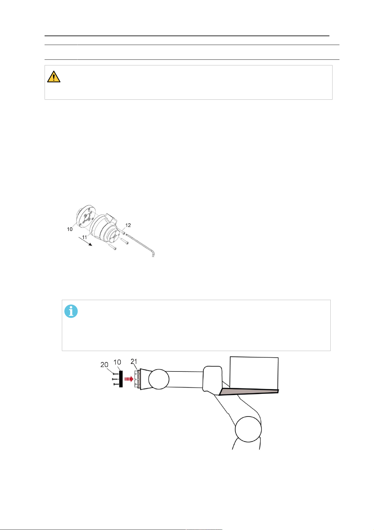
1. Dismount the insulation flange (10) from the RTKS-2 (11) by removing the screws
(12).
2. Position the insulation flange (10) with the index pin on the robot arm and fix it with the
screws (20) included.
The insulation flange (10) is directly compatible with robots with tool flange according
to DIN ISO 9409-1-A40 (diameter 40mm, 4×M6). If the insulation flange (10) does
not fit, use an adapter flange (21).
NOT!
Ensure that the index pin is located correctly. The maximum torque of 1.2Nm
(10.5in.lb) must be observed for the fastening of the adapter flange screws.
Prevent self-loosening of the screws by using suitable thread locking
measures.
3. Mount the RTKS-2 the back on the insulation flange (10).
0463 373 101
- 22 -
© ESAB AB 2018
5 INSTALLATION
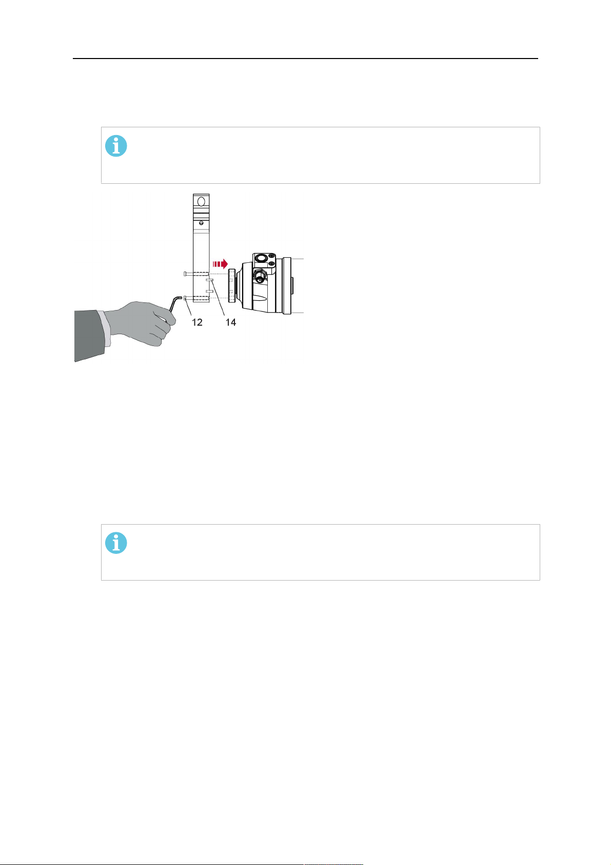
4. Position the mount on the RTKS-2 and carefully insert the cylindrical pins (14) into the
holes provided. Take the position of the torch into account. Two mounting positions
may be potentially possible.
5. Screw the mount evenly using the enclosed cylinder screws with hexagon socket (12).
NOT!
The maximum tightening torque for the cylinder screw (5) is 6Nm (53in.lb)
and the property class category is 8.8.
12 - Cylinder screw with hexagon socket
M6DIN912 (length of the screw depending
on the torch mount)
14 - Cylindrical pins Ø4×20
5.1.1.1 Torch installation with adjustable mount
Torch mounts with a central clamping assembly can only be fastened on the journal of the
mounting flange. For this, the mounting flange must be fastened first.
1. If applicable, carefully press the cylindrical pins (1) into the corresponding holes in the
mounting flange. The pins should protrude by approximately 5 mm (0.2 in.).
2. Position the mount on the safety-off mechanism RTKS-2 and carefully insert the
cylindrical pins (1) into the holes provided. In doing so, take the later position of the
torch into account. Two mounting positions may be potentially possible.
3. Then screw down the mounting flange evenly using the enclosed cylinder screws with
hexagon socket (2).
NOT!
The maximum tightening torque for the cylinder screw (2) is 7.1 Nm (62.8
in.lb) and the property class category is 8.8.
0463 373 101
- 23 -
© ESAB AB 2018

5 INSTALLATION
4. Unscrew the axial cylinder screw with hexagon socket (4) out of the mounting flange
together with the washer (3).
1 - Cylindrical pins Ø4×14 3 - Washer Ø9 mm
2 - Cylinder screw with hexagon socket
M6×16
4 - Axial cylinder screw with hexagon
socket M8×16
5. Place the torch mount (5) onto the journal (6) of the mounting flange, paying attention
while doing so to the exact alignment of the feather key (7) and the corresponding
groove (7a).
6. Insert the clamping mandrel (8) into the lateral hole (see illustration) and position it so
that the mating surfaces (9a) of the clamping mandrel rest on the mating surface (9) of
the journal.
0463 373 101
- 24 -
© ESAB AB 2018

5 INSTALLATION
7. Fix the clamping mandrel from the opposite side using the M6 cylinder screw with
hexagon socket (10) and the Ø22 mm washer (11).
8. Screw the axial cylinder screw (4) with the Ø9 mm washer (3) into the mounting flange
and tighten firmly.
3 - Washer Ø9 mm 8 - Clamping mandrel
4 - Axial cylinder screw with hexagon
9 - Mating surface of mounting flange
socket M8×16
5 - Torch mount 9a - Mating surfaces of clamping mandrel
6 - Mounting flange journal 10 - Cylinder screw with hexagon socket
M6×30
7 Feather key 11 - Washer Ø22×6.4 mm
7a - Groove for feather key
5.1.2 Standard arm cable assembly for KS-2 and FL-2
The cable assembly must be aligned to the intended use in length and design. The type of
cooling for the torch and the cable assembly must be the same (either gas or water cooled
respectively). In order to prevent damage to the torch system and other components, it is
imperative to observe the following instructions.
0463 373 101
- 25 -
© ESAB AB 2018

5 INSTALLATION
DİKKAT!
• Coordinate the length and design of the cable assembly to suit the range of
action of the robot.
• Do not bend, compress or overstretch the cable assembly.
• Fix the cable assembly such that is can be moved freely and cannot become
entangled.
• Any additional holding devices possibly installed, for example a balancer,
must not crush or bend the cable assembly.
• Extreme turning movements must be avoided in which the cable assembly
may become twisted.
• Chafing on the robot or other objects must be excluded.
1. Unscrew the cylinder screws (1) and lift off the top section (2) of the torch mount.
2. Insert the feather key (4) into the recess of the neck support flange (3) from below.
3. Align the neck support flange (3) including the feather key (4) to the groove (5) of the
torch mount and push into the groove right up to the stop of the flange.
4. Hold the cable assembly in this position and simultaneously place the top section (2)
back onto the torch mount. First screw both cylinder screws (1) loosely in to about the
same length, then tighten alternately. The top section (2) of the mount should have an
even gap to the bottom section.
The front part of the cable assembly is directly clamped into the torch mount (see
illustration below).
1 - Cylinder screws 4 - Feather key
2 - Torch mount top section 5 - Groove for feather key
3 - Neck support flange
5.1.3 RTKS-2 wire feeder connection
In order to be able to create the connection, the cable assembly must be mounted as
described in the "Installing the cable assembly" section and equipped following "Installing the
wire guide" section. Only then can the central and media connection take place. Proceed as
described below:
0463 373 101
- 26 -
© ESAB AB 2018

5 INSTALLATION
1. Connect the central connector of the cable assembly (2) to the wire feeder cabinet
socket. Tighten the central connector sleeve nut fingertight. Do not use tools.
1 - Burndy Connector 4 - Return of heated water (red cap)
2 - EURO central connector 5 - Return of heated water (red cap)
3 - Air blow-out 6 - Main Wire feeder
2. For water cooled systems. Connect the water hoses to the cooling circuit. The end of
the hose marked blue (4) is connected to the water outlet, and the end marked red (5)
is connected to the water return.
3. Connect the blow-out line (3) to the corresponding connection of the feeder.
4. Connect the Burndy Connector to the wire feeder. (1) to the feeder. See section
"Electrical connections".
NOT!
All hoses and the control line must be installed so they can not bend or get
damaged!
5.1.4 RTKS-2 electrical connections
5.1.4.1 RTKS-2 safety-off mechanism connection
The switch for the safety-off functionality RTKS-2 is connected through the control cable,
see (3) in the illustration below. This connects to the RTKS-2 unit via the 4-pole plug (4) that
contains circuits for the push-button (6) and the safety-off signal (7).
If a collision is detected, the control circuit for the safety-off signal (7), which is normally
closed, will be interrupted.
Rating of the control circuit: max. 48 V / 1 A
0463 373 101
- 27 -
© ESAB AB 2018

5 INSTALLATION
2 - Burndy connector 5 - RTKS-2 connector for control cable plug
4 - Control cable plug
Burndy konnektör pimleri
A. Dokunmayı Algılayan Gaz
Nozülü
C. Çarpışma sensörü
F. 0V
G. + Motor voltajı
H. - Motor voltajı
D. Çarpışma sensörü
E. Yavaş hareket
If the robot control provides a control circuit for nozzle sense functionality, the connection is
accomplished with a 1-wire connection.
Rating of the control circuit: max 50 V / 5 A.
TEHLİKE!
If the nozzle sense function is not being used, the open end of the control cable on
the power source connection side must be properly isolated in order to avoid short
circuits. During certain problems on the torch head, the full welding potential may be
present on this cable.
DİKKAT!
After detection of contact (gas nozzle on work piece), quickly reduce or cut off the
maximum current in the nozzle sense circuit in order to avoid overloading of the
system.
Allowed load max. 1 minute at the rated nominal current.
5.1.5 RTKS-2 Torch installation
Continue according to section "Torch installation".
0463 373 101
- 28 -
© ESAB AB 2018

5 INSTALLATION
5.2 RTFL-2 standard arm installation
5.2.1 RTFL-2 rigid mount
1. Position the RT FL-2 (2) with the index pin on the robot arm and fix it with the hexagon
socket screw included.
The FL-2 is directly compatible with robots with tool flange according to DIN ISO
9409-1-A40 (diameter 40mm, 4×M6). If the rigid mount does not fit, use an adapter
flange (3).
NOT!
Ensure that the index pin is located correctly. The maximum torque of 1.2Nm
(10.5in.lb) must be observed for the fastening of the adapter flange screws.
Prevent self-loosening of the screws by using suitable thread locking
measures.
2. Install torch mount (1). Only torch mounts having a hole pattern equivalent with the
mounting surface may be attached. If necessary, carefully press the cylindrical pins (4)
into the corresponding holes in the bracket. The pins should protrude by
approximately 5mm (0.2in.). Position the torch mount on the RTFL-2 (2) and
carefully insert the cylindrical pins (4) into the holes provided. Take the position of the
torch into account. Two mounting positions may be potentially possible.
3. Screw the mount evenly using the enclosed cylinder screws with hexagon socket (5).
NOT!
The maximum tightening torque for the cylinder screw (5) is 6Nm (53in.lb)
and the property class category is 8.8.
0463 373 101
- 29 -
© ESAB AB 2018

5 INSTALLATION
4 - Cylindrical pins Ø4×20
5 - Cylinder screw with hexagon socket M6
DIN 912 (length of the screw depending on
the torch mount)
Side view
Torch installation with adjustable mount
Torch mounts with a central clamping assembly can only be fastened on the journal of the
mounting flange. For this, the mounting flange must be fastened first.
1. If applicable, carefully press the cylindrical pins (1) into the corresponding holes in the
mounting flange. Avoid the formation of burrs. The pins should protrude by
approximately 5 mm (0.2 in.).
2. Position the mount on the RTFL-2 and carefully insert the cylindrical pins (1) into the
holes provided. In doing so, take the later position of the torch into account. Two
mounting positions may be potentially possible.
3. Then screw down the mounting flange evenly using the enclosed cylinder screws with
hexagon socket (2).
NOT!
The maximum tightening torque for the cylinder screw (2) is 7.1 Nm (62.8
in.lb) and the property class category is 8.8.
4. Unscrew the axial cylinder screw with hexagon socket (4) out of the mounting flange
together with the washer (3).
1 - Cylindrical pins Ø4×14 3 - Washer Ø9 mm
2 - Cylinder screw with hexagon socket
M6×16
4 - Axial cylinder screw with hexagon
socket M8×16
5. Place the torch mount (5) onto the journal (6) of the mounting flange, paying attention
while doing so to the exact alignment of the feather key (7) and the corresponding
groove (7a).
0463 373 101
- 30 -
© ESAB AB 2018

5 INSTALLATION
6. Insert the clamping mandrel (8) into the lateral hole (see illustration) and position it so
that the mating surfaces (9a) of the clamping mandrel rest on the mating surface (9) of
the journal.
7. Fix the clamping mandrel from the opposite side using the M6 cylinder screw with
hexagon socket (10) and the Ø22 mm washer (11).
8. Screw the axial cylinder screw (4) with the Ø9 mm washer (3) into the mounting flange
and tighten firmly.
3 - Washer Ø9 mm 8 - Clamping mandrel
4 - Axial cylinder screw with hexagon
9 - Mating surface of mounting flange
socket M8×16
5 - Torch mount 9a - Mating surfaces of clamping mandrel
6 - Mounting flange journal 10 - Cylinder screw with hexagon socket
M6×30
7 - Feather key 11 - Washer Ø22×6.4 mm
7a - Groove for feather key
5.2.2 RTFL-2 torch installation
Continue according to section "Torch installation".
5.3 RTKSC-2 hollow wrist system installation
5.3.1 RTKSC-2 mount with safety off mechanism
DİKKAT!
For hollow wrist systems make sure that the clear space around the robot is at least
Ø45 mm (1.8 in.) around the wrist and 50 mm (2.0 in.) near the wire feeder.
0463 373 101
- 31 -
© ESAB AB 2018

5 INSTALLATION
1. Remove the three screws (2) from the front cover (3) of the torch mount and carefully
pull the cover off the RTKSC-2 main body (5). Take care not to damage the micro
switches installed inside the assembly.
1 - Hexagon wrench 4 mm 4 - Rubber boot
2 - 3× M5×12 screws 5 - RT KSC-2 main body
3 - RT KSC-2 front cover
1. Pull off the rubber boot (4) from the RTKSC-2 main body (5) to the front.
2. Now position the RTKSC-2 main body (5) on the adapter flange (7) so that the index
pin is correctly seated. Attach with the screws (6) enclosed.
3. Reinstall the rubber boot (4) on the RTKSC-2 main body (5) and make sure it is
correctly located in the grooves on the front and back flange.
4. Istall the adapter flange (7) on the robot.
Fastening torque max. 2.2 Nm (19.5 in.lb).
1 - Hexagon wrench 4 mm 3 - 3× M5×12 hexagon socket screws
2 - Rubber boot 4 - Adapter flange
5.3.2 Mounting the cable assembly
NOT!
In order to adjust the wire feeder position to the cable assembly length, it must be
mounted on an adjustable support with a possible movement of ±2-3cm (±1in.) to
the back and to the front. The length of the cable assembly must be determined
from the centred mounting position of the wire feeder.
1. Move the robot arm into a completely straight position, see illustration below. Make
sure that (1) axis 6 (rotation around the torch axis) is in 0° position.
2. Move the feeder (3) completely to the back in order to create space for inserting the
cable assembly. If it is not possible to move the feeder sufficiently, it should be
removed from the robot.
0463 373 101
- 32 -
© ESAB AB 2018

5 INSTALLATION
3. Insert the cable assembly with the coupling (2) first into the robot arm and feed it
through the robot wrist.
4. The feeder should only be installed again after the correct mounting position with
respect to the cable length has been determined. (See section "Installing the cable
assembly").
DİKKAT!
Axis 6 must be in 0° position.
5.3.2.1 RTKSC-2 feeder cabinet connections
When installed for the first time, the position of the wire feeder cabinet must be adjusted to
the length of the cable assembly. First, the robot arm must be fully extended (straight).
DİKKAT!
As long as the correct position of the feeder corresponding to the length of the cable
assembly has not been determined, be careful when moving the robot arm and
avoid overstretching the cable. It is helpful to loosen the positioning screws of the
feeder before moving the robot arm to allow the feeder to follow the cable assembly.
0463 373 101
- 33 -
© ESAB AB 2018

5 INSTALLATION
1. Loosen the sliding mechanism of the wire feeder and connect the cable assembly.
2. Now adjust the position of the wire feeder to suit the length of the Infiniturn or Helix
cable, as indicated with "A" in the illustration below.
DİKKAT!
When adjusting the position of the feeder cabinet, make sure that the cable
assembly is not under stress when the robot arm is in stretched-out position.
It is normal for the cable assembly to sag slightly, it should never be taut.
3. Before securing the wire feeder in its permanent position, ensure that the Euro
connectors are tightly connected. Then turn the torch mount down and up again
(rotating on the axis 5), in order not to tighten the cable assembly too much against
the feeder (see illustration above). Once this is done, tighten the feeder in that
position.
4. For water cooled systems, connect the water lines to the cooling circuit. See section
"Cable assemblies for hollow wrist systems" in the TECHNICAL DATA chapter for
indications.
The hose with the blue rubber cap is for cooling water to the torch, the hose with the
red rubber cap returns the heated water. Make sure the hoses will not kink or get
otherwise blocked.
NOT!
A Helix cable assembly used for a gas cooled system must not be connected
to a cooling circuit. As the water connections are not needed, they may be cut
off.
5. Connect the blow-out hose (black rubber cap) to the corresponding outlet of the wire
feeder.
NOT!
If the blow-out function is not used, the blow-out hose must be sealed with the
rubber cap enclosed. With Infiniturn systems, the blow-out air must be
supplied to the corresponding connection hose, if it is not permitted to connect
blow-out air to the shield gas connection!
6. Install the necessary plug on the control cable and connect it to the safety off circuit
interface of the wire feeder (see section "Electrical connections").
0463 373 101
- 34 -
© ESAB AB 2018

5 INSTALLATION
5.3.3 RTKSC-2 cable assembly
The cable assembly must be aligned to the intended use in length and design. The type of
cooling for the torch and the cable assembly must be the same (either gas or water cooled
respectively). In order to prevent damage to the torch system and other components, it is
imperative to observe the following instructions.
DİKKAT!
• Coordinate the length and design of the cable assembly to suit the range of
action of the robot.
• Do not bend, compress or overstretch the cable assembly.
• Fix the cable assembly such that is can be moved freely and cannot become
entangled.
• Any additional holding devices possibly installed, for example a balancer,
must not crush or bend the cable assembly.
• Extreme turning movements must be avoided in which the cable assembly
may become twisted.
• Chafing on the robot or other objects must be excluded.
5.3.3.1 RTKSC-2 cable assembly installation
NOT!
For some robots, it may be possible to deviate from this order, and first connect the
cable assembly to the RTKSC-2, then thread the cable from the front through the
robot arm. If in doubt, follow the suggested order.
1. Loosen the three screws (7) with the associated washers and remove them from the
RTKSC-2 cover (1). See illustration below.
2. Install the supplied O-rings (4) into the grooves in the cover (1).
3. Pull the cable assembly approximately 15 cm (6 in.) from the main body (3).
0463 373 101
- 35 -
© ESAB AB 2018

5 INSTALLATION
4. Insert the coupling (2) into the socket of the cover (1) as shown. Align the index pin (6)
with the index hole (5) in the main body and insert completely.
NOT!
Make sure that the position of the O-rings are not shifted by the index pin
during the assembly.
1 - RTKSC-2 cover 5 - Index hole
2 - Coupling 6 - Index pin
3 - RTKSC-2 main body 7 - 3× M5×35 screws
4 - 3× O-ring for water cooled systems 11 - Control cable connector
5. Insert the three screws (7) with the associated washers (8) and tighten gently with the
enclosed hexagonal wrench, see below illustration.
Fastening torque approximately 2 Nm (18 in.lb).
0463 373 101
- 36 -
© ESAB AB 2018

5 INSTALLATION
6. If present, insert the control cable plug (10) into the connector (11) and make sure it is
firmly seated.
7 - 3× M5×35 screw 11 - Control cable connector
8 - Washer 12 - 2× Micro switch
10 - Control cable plug 13 - Index pin
7. Gently push back the cable assembly into the robot arm and carefully seat the
RTKSC-2 cover (1) in place. Observe the index pin (13) to be in the correct position.
Make sure the two micro switches (12) are not damaged if present.
8. Insert the three M5 screws (14) and tighten without excessive force.
13. Index pin
14. 3× M5×12 screws
0463 373 101
- 37 -
© ESAB AB 2018

5 INSTALLATION
5.3.3.2 RTKSC-2 electrical connections
NOT!
After connecting the control cable, secure the cable in order to protect it from getting
caught while the robot is moving.
Usually, the control cable will be directly connected to the wire feeder. See the
manufacturer's documentation for details. The link to the robot control is then
implemented via the power source controller.
RTKSC-2 safety-off mechanism connection
The switch for the safety-off functionality RTKSC-2 is connected through the control cable,
see (3) in the illustration below. This connects to the RTKSC-2 unit via the control cable plug
(1).
The safety-off signal requires a 2-wire connection (black/black) to the safety-off circuit in the
robot control (5).
If a collision is detected, the control circuit (normally closed) will be interrupted (4).
Rating of the control circuit: max. 48 V / 1 A.
1 - Control cable plug 3 - Burndy connector VVV
2 - EURO central connector
Burndy konnektör pimleri
A. Dokunmayı Algılayan Gaz
Nozülü
C. Çarpışma sensörü
F. 0V
G. + Motor voltajı
H. - Motor voltajı
D. Çarpışma sensörü
E. Yavaş hareket
RTKSC-2 nozzle sense function connection
If the robot control provides a control circuit for nozzle sense functionality.
The connection is accomplished with a 2-wire connection (black/black) to the nozzle sense
circuit in the robot control (5), see illustration below.
0463 373 101
- 38 -
© ESAB AB 2018

5 INSTALLATION
Usually, the control cable will be directly connected to the wire feeder. See the
manufacturer's documentation for details. The link to the robot control is then implemented
via the power source robot interface.
Rating of the control circuit: max. 50 V / 5 A.
TEHLİKE!
If the nozzle sense function is not being used, the open end of the control cable on
the power source connection side must be properly isolated in order to avoid short
circuits. During certain problems on the torch head, the full welding potential may be
present on this cable.
DİKKAT!
After detection of contact (gas nozzle on work piece), quickly reduce or cut off the
maximum current in the nozzle sense circuit in order to avoid overloading of the
system.
Allowed load max. 1 minute at the rated nominal current.
1 - Control cable plug 3 - Control cable
2 - EURO central connector
5.3.4 RTKSC-2 torch installation
Continue according to section "Torch installation".
0463 373 101
- 39 -
© ESAB AB 2018

5 INSTALLATION
5.4 RTFLC-2 installation
5.4.1 RTFLC-2 mount
1. Remove the three M5 screws (2) from the front cover (3) of the RT FLC-2 torch mount
and carefully pull the cover off the main body (4).
1 - Hexagon wrench 4 mm 3 - RT FLC-2 front cover
2 - 3× M5×12 screws 4 - RT FLC-2 main body
2. Now position the RT FLC-2 main body (4) on the adapter flange (6) so that the index
pin is correctly seated. Attach with the screws (5) enclosed
Fastening torque max. 2.2 Nm (19.5 in.lb).
1 - Hexagon wrench 4 mm 5 - 3× M5×12 hexagon socket screws
4 - RT FLC-2 main body 6 - Adapter flange
5.4.2 RTFLC-2 wire feeder connection
5.4.2.1 Feeding through the robot arm
NOT!
In order to adjust the wire feeder position to the cable assembly length, it must be
mounted on an adjustable support with a possible movement of ± 2-3 cm (± 1 in.) to
the back and to the front. The length of the cable assembly must be determined
from the centred mounting position of the wire feeder.
0463 373 101
- 40 -
© ESAB AB 2018

5 INSTALLATION
1. Move the robot arm into a completely straight position, see illustration below. Make
sure that (1) axis 6 (rotation around the torch axis) is in 0° position.
2. Move the feeder (3) completely to the back in order to create space for inserting the
cable assembly. If it is not possible to move the feeder sufficiently, it should be
removed from the robot.
3. Insert the cable assembly with the coupling (2) first into the robot arm and feed it
through the robot wrist.
4. The feeder should only be installed again after the correct mounting position with
respect to the cable length has been determined. (See section "Installing the cable
assembly").
DİKKAT!
Important! Axis 6 must be in 0° position.
5.4.2.2 RTFLC-2 feeder cabinet connections
When installed for the first time, the position of the wire feeder cabinet must be adjusted to
the length of the cable assembly. First, the robot arm must be fully extended (straight).
DİKKAT!
As long as the correct position of the feeder corresponding to the length of the cable
assembly has not been determined, be careful when moving the robot arm and
avoid overstretching the cable. It is helpful to loosen the positioning screws of the
feeder before moving the robot arm to allow the feeder to follow the cable assembly.
0463 373 101
- 41 -
© ESAB AB 2018

5 INSTALLATION
1. Loosen the sliding mechanism of the wire feeder and connect the cable assembly.
Refer to the instruction of the feeder manufacturer.
2. Now adjust the position of the wire feeder to suit the length of the Infiniturn or Helix
cable, as indicated with "A" in the illustration below.
DİKKAT!
When adjusting the position of the feeder cabinet, make sure that the cable
assembly is not under stress when the robot arm is in stretched-out position.
It is normal for the cable assembly to sag slightly, it should never be taut.
3. Before securing the wire feeder in its permanent position, ensure that the Euro
connections are tightly connected. Then turn the torch mount down and up again
(rotating on the axis 5), in order not to tighten the cable assembly too much against
the feeder (see illustration above). Once this is done, tighten the feeder in that
position.
4. For water cooled systems, connect the water lines to the cooling circuit. See section
"Cable assemblies for hollow wrist systems" in the TECHNICAL DATA chapter for
indications.
The hose with the blue rubber cap is for cooling water to the torch, the hose with the
red rubber cap returns the heated water. Make sure the hoses will not kink or get
otherwise blocked.
NOT!
A Helix cable assembly used for a gas cooled system must not be connected
to a cooling circuit. As the water connections are not needed, they may be cut
off.
5. Connect the blow-out hose (black rubber cap) to the corresponding outlet of the wire
feeder.
NOT!
If the blow-out function is not used, the blow-out hose must be sealed with the
rubber cap enclosed. With Infiniturn systems, the blow-out air must be
supplied to the corresponding connection hose, if it is not permitted to connect
blow-out air to the shield gas connection!
0463 373 101
- 42 -
© ESAB AB 2018

5 INSTALLATION
6. Install the necessary plug on the control cable and connect it to the safety off circuit
interface of the wire feeder (see section "Electrical connections").
5.4.3 RTFLC-2 cable assembly
The cable assembly must be aligned to the intended use in length and design. The type of
cooling for the torch and the cable assembly must be the same (either gas or water cooled
respectively). In order to prevent damage to the torch system and other components, it is
imperative to observe the following instructions.
DİKKAT!
• Coordinate the length and design of the cable assembly to suit the range of
action of the robot.
• Do not bend, compress or overstretch the cable assembly.
• Fix the cable assembly such that is can be moved freely and cannot become
entangled.
• Any additional holding devices possibly installed, for example a balancer,
must not crush or bend the cable assembly.
• Extreme turning movements must be avoided in which the cable assembly
may become twisted.
• Chafing on the robot or other objects must be excluded.
5.4.3.1 RTFLC-2 cable assembly installation
In a hollow wrist system the recommended order of installation is to feed the cable assembly
through the robot arm before connecting the cables to the torch mount.
When the cable assembly is correctly installed in the hollow wrist, continue the installation
according to the procedure described below.
NOT!
For some robots, it may be possible to deviate from this order, and first connect the
cable assembly to the RTKSC-2 and RTFLC-2, then thread the cable from the front
through the robot arm. If in doubt, follow the suggested order.
1. Loosen the three screws (7) with the associated washers and remove them from the
RTFLC-2 cover (1). See illustration below.
2. Install the supplied O-rings (4) into the grooves in the cover (1). For gas cooled
systems, only one O-ring (4a) is needed, for water cooled systems all three O-rings
are needed.
3. Pull the cable assembly approximately 15 cm (6 in.) from the main body (3).
0463 373 101
- 43 -
© ESAB AB 2018

5 INSTALLATION
4. Insert the coupling (2) into the socket of the cover (1) as shown. Align the index pin (6)
with the index hole (5) in the main body and insert completely.
NOT!
Take great care that the position of the O-rings is not shifted by the index pin
during the assembly.
1 - RT FLC-2 cover 5 - Index hole
2 - Coupling 6 - Index pin
3 - RT FLC-2 main body 7 - 3× M5×35 screws
4 - 3× O-ring for water cooled systems 11 - Control cable connector
5. Insert the three screws (7) with the associated washers (8) and tighten gently with the
enclosed hexagonal wrench, see below illustration.
Fastening torque approximately 2 Nm (18 in.lb).
0463 373 101
- 44 -
© ESAB AB 2018

5 INSTALLATION
6. If present insert the control cable plug (10) into the connector (11) and make sure it is
firmly seated.
7 - 3× M5×35 screw 11 - Control cable connector
8 - Washer 12 - 2× Micro switch
10 - Control cable plug 13 - Index pin
7. Gently push back the cable assembly into the robot arm and carefully seat the
RTFLC-2 cover (1) in place. Observe the index pin (13) to be in the correct position.
Make sure the two micro switches (12) are not damaged if present.
8. Insert the three M5 screws (14) and tighten without excessive force.
13 - Index pin 14 - 3x M5x12 screws
0463 373 101
- 45 -
© ESAB AB 2018

5 INSTALLATION
5.4.4 RTFLC-2 electrical connections
NOT!
After connecting the control cable, secure the cable in order to protect it from getting
caught while the robot is moving.
Usually, the control cable will be directly connected to the wire feeder. See the
documentation of the manufacturer for details. The link to the robot control is then
implemented via the power source controller.
5.4.4.1 RTFLC-2 hollow wrist system with Infiniturn cable assembly
Connecting the nozzle sense function
If the robot control provides a control circuit for nozzle sense functionality.
The connection is accomplished with a 2-wire connection (black/black) to the nozzle sense
circuit in the robot control (5), see illustration below.
Usually, the control cable will be directly connected to the wire feeder. See the
manufacturer's documentation for details. The link to the robot control is then implemented
via the power source robot interface.
Rating of the control circuit: max. 50 V / 5 A.
TEHLİKE!
If the nozzle sense function is not being used, the open end of the control cable on
the power source connection side must be properly isolated in order to avoid short
circuits. During certain problems on the torch head, the full welding potential may be
present on this cable.
DİKKAT!
After detection of contact (gas nozzle on work piece), quickly reduce or cut off the
maximum current in the nozzle sense circuit in order to avoid overloading of the
system.
Allowed load max. 1 minute at the rated nominal current.
1 - Control cable plug 3 - Control cable
2 - EURO central connector
0463 373 101
- 46 -
© ESAB AB 2018

5 INSTALLATION
5.4.4.2 RTFLC-2 hollow wrist system with Helix cable assembly
Connecting the nozzle sense function
If the robot control provides a control circuit for nozzle sense functionality.
The connection is accomplished with a 1-wire connection (green) to the nozzle sense circuit
in the robot control (5), see illustration below.
Usually, the control cable will be directly connected to the wire feeder. See the
manufacturer's documentation for details. The link to the robot control is then implemented
via the power source robot interface.
Rating of the control circuit: max. 50 V / 5 A.
TEHLİKE!
If the nozzle sense function is not being used, the open end of the control cable on
the power source connection side must be properly isolated in order to avoid short
circuits. During certain problems on the torch head, the full welding potential may be
present on this cable.
DİKKAT!
After detection of contact (gas nozzle on work piece), quickly reduce or cut off the
maximum current in the nozzle sense circuit in order to avoid overloading of the
system.
Allowed load max. 1 minute at the rated nominal current.
1 - Control cable plug 3 - EURO central connector
2 - Control cable 4 - Burndy connector
5.5 Torch installation
Be sure to use the correct version of the torch mount and cable assembly (water or gas
cooled).
5.5.1 Torch neck equipment
The torch neck, see (1) in the illustration below, must always be equipped to suit the wire
diameter and material.
0463 373 101
- 47 -
© ESAB AB 2018

5 INSTALLATION
1. Select the correct wire guide, contact tip (4), tip holder (2), gas nozzle (5), and gas
diffuser/spatter protection (3). You will find an exact overview and possible alternative
equipment elements for various torch models in the spare parts list. Only use original
ESAB parts; only then is the fitting accuracy ensured.
2. Firmly tighten the tip holder and the contact tip using a suitable tool for example the
enclosed monkey wrench.
3. When using a split wire guide, remove the installed guide nipple including the o-ring
from the torch flange upon delivery if necessary (see section "Installing the neck
liner").
DİKKAT!
The torch must be completely equipped before welding, especially the gas
diffuser and/or spatter protection and all necessary insulators have to be
installed according to the spare parts list. Welding without these items may
cause immediate destruction of the torch.
1 - Torch neck 4 - Contact tip
2 - Tip holder 5 - Contact tip
3 - Gas diffuser
5.5.2 Aristo RT torch neck installation
NOT!
Check the O-rings on the flange of the torch neck before mounting. Replace the
O-rings if damaged or lost. Missing or faulty O-rings will lead to leaks of shielding
gas and coolant.
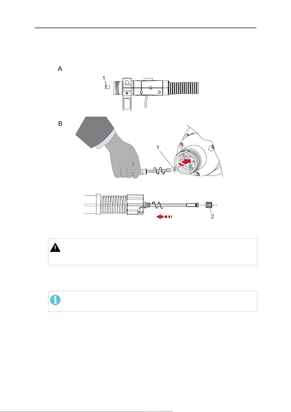
1. For hollow wrist systems, insert the torch into the torch mount in the correct
orientation, so that the locator pin fits into the slot of the RTKSC-2 or RTFLC-2
interface, see (A) in the illustration below. For standard systems, attach the torch to
the RT flange of the cable assembly, (B) in the illustration below.
Installation is only possible in the correct orientation.
2. Tighten the locking nut of the torch neck.
NOT!
Only tighten by hand, never use tools or excessive force.
0463 373 101
- 48 -
© ESAB AB 2018

5 INSTALLATION
3. The correct seating of the torch can be checked by means of the window (1). If the
torch has been correctly mounted, no gap should be seen through the window (1).
5.6 Installing the wire guide for standard and hollow Wrist arm
Installing the wire guide
Choose the wire guide or liner depending on the filler wire material and diameter to be used,
see the spare parts list. Accurate performance of the system can only be guaranteed when
using original ESAB wire guides.
The recommended wire guide is the split wire guide, which consists of the neck liner and a
separate guide in the cable assembly. The front part of the wire guide, which is most
stressed, can be exchanged easily and independently of the cable assembly wire guide.
For correct installation, the following steps must be followed (example for Euro central
connector).
5.6.1 Installing the neck liner
The neck liner must be selected to fit the material and diameter of the welding wire, see the
spare parts list.
0463 373 101
- 49 -
© ESAB AB 2018

5 INSTALLATION
1. If present, remove the central guide nipple (1), from the torch neck using a hexagon
wrench (size 6 mm) or a large flat-blade screwdriver.
NOT!
The guide nipple (1) can only be used with one-piece liners and must not be
used with the standard RT or hollow wrist system.
2. When replacing the neck liner:
Unfasten the sleeve nut and remove the torch neck.
Unfasten the liner nipple using a hexagon wrench (size 6 mm) and remove nipple and
liner from the torch neck.
3. Remove the gas nozzle and the contact tip.
4. Insert the new neck liner (2) into the torch. Carefully tighten the guide nipple using a
suitable tool, e.g. a hex-wrench (size 6 mm) or a large flat-blade screwdriver.
5. Cut the neck liner flush with the tip holder and remove the neck liner from the torch.
6. Install the contact tip.
7. Insert the neck liner again. It will be stopped by the contact tip. Measure the excess
liner sticking out of the neck.
8. Remove the liner again and shorten the front end by the measured length. Carefully
deburr the edge and make sure that the inner hole is not blocked.
9. Reinstall the neck liner and tighten the guide nipple in the neck.
5.6.2 Installing a split wire guide in the cable assembly
The correct liner must be inserted to suit the filler material and the wire diameter, see the
spare parts list.
The wire guide is inserted through the cable assembly from the rear, reaching the guide
nipple that is installed in the flange where the torch neck will be attached. The following
worksteps must be followed in order to correctly determine the wire guide length. (Example
for Euro central connector).
0463 373 101
- 50 -
© ESAB AB 2018
5 INSTALLATION
1. For standard RT system: Install the guide nipple (1) in the center hole of the neck
support flange, see illustration A below.
For hollow wrist system: Install the guide nipple (1) into the torch interface of the
RTKSC-2 / RTFLC-2 cover, see illustration B below.
2. Remove the sleeve nut (2) from the central connector, and remove the old wire guide.
3. Insert the wire guide through the central connection and push forwards as far as it will
go into the guide nipple (1), applying light pressure.
DİKKAT!
Ensure that the wire guide has advanced right up to the stop at the front,
rotating and pushing forward gently.
4. Measure the excess length that needs to be cut from the wire guide.
5. Remove the wire guide again and shorten the front end by the measured length.
Steel liner: grind down the burred edges if needed.
Plastic liner: make a clean cut and chamfer the edges (e.g. with a pencil sharpener)
NOT!
Make sure the inner opening of the liner is not obstructed by the cut wire end.
0463 373 101
- 51 -
© ESAB AB 2018

5 INSTALLATION
6. Reinstall the wire guide and attach the sleeve nut (2).
NOT!
For hollow wrist systems where Infiniturn and Helix cable assemblies are
used, wire guides should be installed without tension so that the ends of the
liners may rotate freely.
Important note when using a plastic liner:
The wire channel between the drive rolls of the feeder and the central
connector of the torch must be fitted with a plastic liner. Depending on the
design of the feeder, a piece of plastic liner inserted into a brass guide tube
can be used.
During wire run-in, make sure that the wire is fed correctly into the plastic liner
of the torch. If necessary, remove the cable assembly from the feeder and
insert the wire, then reattach.
5.6.3 Installing a continuous wire guide in the cable assembly
Installing a steel liner
The wire guide is inserted through the cable assembly from the rear and reaches to the
contact tip. The following worksteps must be followed for the correct calculation of the length
(example for Euro central connector):
1. Install the torch (see section "Torch neck equipment").
2. Remove the gas nozzle and contact tip from the torch.
3. Remove the sleeve nut (D) from the Euro connector.
4. Push in the liner through the central connector and fix with the sleeve nut.
5. Cut off the liner flush with the nozzle holder. To determine the thread projection of the
contact tip, pull the liner backwards and screw in the contact tip.
6. Push the liner forwards as far as it will go to the contact tip applying light pressure on
the liner and measure the length to be shortened at the rear.
7. Now remove the liner again and cut the excess length measured off it’s front end. If
needed, grind down the burred edges. Make sure the inner opening of the liner is not
obstructed by the cut wire end.
8. The insulation of the liner must be removed after cutting off in the front area, such that
the insulation protrudes out of the RM2 flange by approx. 5 cm. For this, briefly
remove the torch neck.
9. Push the liner back in again and fix with the sleeve nut (D), see above. Re-install the
gas nozzle.
0463 373 101
- 52 -
© ESAB AB 2018

5 INSTALLATION
Installing a plastic liner
1. Mount the torch neck (see section "Torch neck equipment") and equip it with a gas
nozzle and contact tip.
2. Remove the sleeve nut (D) from the Euro connector.
3. Cleanly cut off the liner, slightly break the outer edges, point slightly (e.g. with a pencil
sharpener).
4. Insert the liner through the central connector into the cable assembly with fitted torch.
If it gets stuck, rotate the liner to free it and facilitate installation.
NOT!
Make sure the liner is completely inserted by rotating it and slightly pushing it
forward, until you can feel it has reached its stop.
5. Mount the nipple (B) and the O-Ring (C), move it to the right position and fix it with the
sleeve nut (D) of the Euro central connector.
6. Measure the required overlap needed inside the wire feeder cabinet and cut the liner
accordingly.
5.7 Adjust the narrow gap contact tip
The adjusting tool RT42-NG is designed for the narrow gap torch necks RT42W-NG,
RT42G-NG and RT 82W-0°NG, torches with curved narrow gap contact tip. It facilitates the
precisely repeatable and fast changing of the curved contact tip.
NOT!
The adjusting tool must be securely fastened to a stable base, in order to prevent
the position of the device in relation to the robot cannot change unintentionally. If the
exact orientation of the device is lost, the alignment of the contact tip used for the
elaboration of the welding programs can no longer be reproduced with precision.
Select a position within the operating range of the robot for orientation (alignment) of the
contact tip to the torch. Fasten the adjusting tool firmly to a base using the fastening grooves
provided for this purpose. Fastening material is not included with the adjusting tool. Select
fastening material (screws) to suit the existing conditions.
Save all motion sequences and stop positions required to change or align the wearing parts
to a separate robot program.
Before programming the welding tasks: plan at which orientation the contact tip is to stand in
relation to the torch. The torch must then be positioned in the desired rotational position and
the contact tip aligned using the adjusting device. Only then may the welding task be
programmed. If different orientations of the contact tip are required for various welding tasks,
the contact tip has to be aligned to the new position when the welding task is changed.
UYARI!
The gas nozzle and the torch head become very hot during welding. Always allow
the torch to cool down before replacing wearing parts or adjusting the contact tip.
0463 373 101
- 53 -
© ESAB AB 2018

5 INSTALLATION
Adjust the contact tip
Move the robot torch to a position parallel to
the opening of the adjusting tool (2). Maintain
a sufficient distance to the work table to be
able to comfortably remove the gas nozzle.
Define this position in your robot program as
the wearing parts change position (stop
position 1).
Remove the gas nozzle by pulling it
downwards. Remove the welding wire in the
contact tip if necessary.
Loosen the counter nut (4) of the contact tip
while counter-holding the nozzle holder at the
wrench flat (3).
Unscrew the contact tip including the counter
nut from the nozzle holder and replace the
nozzle holder if necessary.
Completely screw the counter nut (4) onto the
new contact tip. Screw the contact tip
including the counter nut into the nozzle
holder.
Align the contact tip until it is parallel to the
opening of the adjusting tool. If necessary,
slightly unscrew the contact tip so that it can
be easily turned in both directions.
0463 373 101
- 54 -
© ESAB AB 2018

5 INSTALLATION
NOT!
The contact tip must be able to be
easily moved by hand in both
directions in order to enable the
threading of the adjusting tool.
Place the robot torch or contact tip directly in
front of the opening of the adjusting tool (2)
(stop position 2).
Insert it slowly from the front until it is
completely inserted into the device (stop
position 3).
The contact tip was aligned exactly in the
device during insertion. Now cautiously
tighten the counter nut (4) in this position,
while counter holding the nozzle holder at the
wrench flat.
Slowly move the robot torch out of the
adjusting gauge, return to stop position 1 and
push on the gas nozzle as far as it will go.
Allow the welding wire to run into the contact
tip and bring the robot arm into welding
position.
0463 373 101
- 55 -
© ESAB AB 2018

6 OPERATION
6 OPERATION
DİKKAT!
Before starting the system, check the whole installation according to the
manufacturer's instructions and applicable safety regulations.
Check the following to make sure that the system has been installed correctly:
1. Are all parts securely attached (torch, torch mount, flanges, safety-off device, cable
assembly, and wire feeder cabinet)?
2. Are all media hoses connected correctly and protected from damage?
3. Is the EURO central connector or direct connector fastened tightly?
4. Is the cable assembly length correct and suitable for the installation and can the cable
rotate freely? The cable must not be bent sharply. Any risk of the cable getting caught
on another object must be eliminated.
5. Is the control cable of the safety-off circuit connected and functioning? Move torch by
hand to test (RTKSC-2 and RTKS-2 only).
6. Is the torch firmly attached and is it completely equipped?
7. Is the wire guide installed according to the manual?
8. Are all lines and tubes arranged so that they cannot be damaged or bent?
The wire run-in can now be started, either via the wire run-in pushbutton or via the wire run-in
at the feeder.
6.1 Important information for programming (hollow wrist system only)
Fast rotation of axis 6 of the robot will significantly stress the cable assembly. In certain
cases, this can lead to damage or destruction of the cable. In order to maximize the lifetime
of the cable, we strongly suggest respecting the following limitations when programming the
robot.
Position of axis 5 Max. rotational speed of axis 6
0 – 60° 100 % (no limitations)
60° – 80° 300°/sec (approximately 50 % of max. robot speed)
> 80° 120°/sec (approximately 20 % of max. robot speed)
NOT!
The above values are only indications. For information on the exact rotational speed
limits, refer to the individual robot manual or contact the robot supplier.
To reposition the torch quickly, the robot arm may have to be slightly extended first to achieve
a bending angle of max. 60° of axis 5. In this position, the maximum available rotation speed
of axis 6 can be used.
When using the ESAB Helix cable assembly, the max. rotation of ±270° from the neutral
position must not be exceeded.
0463 373 101
- 56 -
© ESAB AB 2018

6 OPERATION
DİKKAT!
While axis 5 is bent more than 60°, the rotational speed of the torch around axis 6
must be limited, see table above.
Otherwise, the cable assembly may be damaged.
0463 373 101
- 57 -
© ESAB AB 2018

7 SERVİS VE BAKIM
7 SERVİS VE BAKIM
UYARI!
Sistemde bakım yapılmadan önce montaj ana güç kaynağı kapatılmalıdır. Bu
kılavuzun başındaki güvenlik düzenlemelerine dikkat edin.
Hasarlı üfleç veya kablo grupları kullanılmamalıdır! Bilinen arızalar, donanımların bir
sonraki kullanımından önce kalifiye personel tarafından onarılmalıdır.
UYARI!
Yanma ve yaralanma tehlikesi! Gaz nozülü ve üfleç kafası, kaynak sırasında çok
ısınır. Bakım işlemine başlamadan önce üflecin soğumasını bekleyin.
UYARI!
Yaralanmayı veya tesisinizin zarar görmesini engellemek için bu talimatlara uyun:
1. RTKSC-2 veya RTFLC-2 üfleç desteği, RTKS-2 güvenlik amaçlı kapatma
mekanizması, kablo grubu veya Infiniturn ortam bağlantısı yalnızca ESAB
servis destek bölümü tarafından onarılmalıdır.
2. Infiniturn ortam bağlantısı hiçbir zaman açılmamalıdır. Kullanıcı tarafından
servis işlemi yapılabilecek bir parçası yoktur ve parçalarına ayrıldığında
kullanılmaz hale gelecektir.
3. RTKSC-2 veya RTKS-2'yi hiçbir zaman parçalarına ayırmayın. Bu, yay
yüklü bir mekanizmadır. Üzerinde hatalı bir işlem yaparsanız ciddi şekilde
yaralanabilirsiniz.
7.1 Zorunlu kontrol ve işlemler
Her kullanımdan önce:
• Üfleç, temas ucu, gaz nozülü, muylu pulu, kablolar ve tüm donanımlarda genel bir
hasar olup olmadığını kontrol edin.
NOT!
Bekleme sürelerini en aza indirmek için iki üfleç muylusu arasında sırayla
çalışmanız ve her zaman kullanıma hazır yeni bir üfleç muylusu bulundurmanız
önerilir.
Her 8 saatlik kullanımda (uygulamaya bağlı olarak):
• Kontak ucunu değiştirin.
Günlük:
• Güvenlik amaçlı kapatma mekanizmasının işlevini elinizle kontrol edin.
• Gözle hasar kontrolü yapın (bükülme veya çatlama gibi).
• Tel besleyicinin konumunun doğru olduğunu kontrol edin. Kablo grubu çok gergin
olmamalı veya sarkmamalıdır.
• Ortam bağlantıları ve Infiniturn ortam bağlantısında kaçak olup olmadığını kontrol edin.
• Üfleç kılavuzuna uygun şekilde üflecin temizlik ve bakım işlemlerini yapın.
Her 40 saatlik kullanımda (uygulamaya bağlı olarak):
• Tel kılavuzlarını değiştirin.
• Muylu kılavuzlarını değiştirin.
Haftada bir veya kullanıma bağlı olarak ihtiyaç olduğunda:
0463 373 101
- 58 -
© ESAB AB 2018

7 SERVİS VE BAKIM
• Tel kılavuzunu çıkarın, aşınma ve kir birikintisi olup olmadığını kontrol edin. Gerekiyorsa
değiştirin.
Ayda bir veya yoğun kullanımda (örneğin günde 8 saatten fazla) daha sık:
• Kablo kılavuz kanalını basınçlı havayla temizleyin (kontak ucunu ve kablo kılavuzunu
sökün).
• Tüm vidaların sıkıldığından emin olun.
• Tüm bağlantılarda ve hortumlarda hasar olup olmadığını kontrol edin.
• 250 kg'lık telin tamamı kaynatıldığında değiştirin.
Sistemi güvenli bir şekilde çalıştırabilmek için elektrik yalıtımındaki hasarlar eğitimli personel
tarafından onarılmalıdır.
0463 373 101
- 59 -
© ESAB AB 2018

8 SORUN GİDERME
8 SORUN GİDERME
Arıza Olası neden Aksiyon
Tel
beslenemiyor
Kaynak teli, kablo grubuna
beslemeden önce
düzleştirilmemiştir
Üfleç ve kablo grubu, tel çapı ve
malzemesine uygun ve doğru
şekilde donatılmamıştır
Tel kılavuzu kablo grubuna doğru
şekilde yerleştirilmemiştir
Temas ucu, tel döküntüleri ile
engellenmektedir
Tel kılavuzu aşınmıştır
Tel besleyici, üfleçteki kir ve
döküntüler nedeniyle
engellenmektedir
Gerekirse kaynak kablosunu tekrar
dışları çekip çıkarın, ucu kesip
çapaklarını alın ve kablonun ilk 10
cm'lik kısmını düzleştirin. Ardından,
kablo grubuna geri takın.
Kablo kılavuzunu (kablo grubu ve
üfleç muylusu) ve kontak ucunu
kontrol edin.
Tel kılavuzunu Euro konnektörden
biraz dışarıya doğru çekin. Tel
kılavuzunu takarken, son birkaç
santimetrenin üfleç arabirimindeki
kılavuz nipele doğru hafifçe
kaydığını hissetmelisiniz. Aksi
takdirde, kablo kılavuzu çok kısa
olabilir ve tamamen takılmayabilir.
Kontak ucunu ve/veya kablo
kılavuzu değiştirin; üfleç muylusunu,
kablo kılavuzu kanalını ve kablo
kılavuzunu basınçlı havayla
temizleyin.
Üfleç aşırı
ısınıyor
Kablo besleme
sorunları
Temas ucu veya uç tutucusu doğru
sıkılmamıştır
Elle sıkma işlemi için uygun bir alet
kullanın.
Soğutma sistemi doğru çalışmıyor Su debisini, dolum seviyesini ve
temizliğini kontrol edin.
Soğutma sistemi doğru şekilde
bağlanmamıştır
Bağlantıları (su girişi ve dönüşü)
kontrol edin.
Üfleç çok fazla geriliyor Teknik verileri uygulayın ve
gerekirse farklı bir tip seçin.
Kablo grubu arızalı Kabloları, boruları ve bağlantıları
kontrol edin.
Temas ucu aşınmıştır Kontak ucunu değiştirin.
Koruma aşınmıştır/kirlidir Pulu kontrol edin, hava tutun.
Gerekiyorsa değiştirin.
Sarf malzemeleri, tel çapına veya
Yedek parça listesini kontrol edin.
malzemeye uygun değildir
Tel besleyici doğru şekilde
ayarlanmamıştır
Kablo beslemesi silindirlerini, temas
basıncını ve makara frenini kontrol
edin.
Kablo grubu bükülmüş veya çok
küçük yarıçaplı dönüşler olacak
şekilde yerleştirilmiştir
Kablo grubunda hasar olup
olmadığını kontrol edin. Pul kolayca
takılabiliyor mu? Talimatlara uygun
şekilde takın. "Kablo grubunun
takılması" bölümüne bakın.
0463 373 101
Tel kirlenmiştir Temizleme keçesi kullanın.
- 60 -
© ESAB AB 2018

8 SORUN GİDERME
Arıza Olası neden Aksiyon
Kablo
Kablo makarası boş Kablo beslemesinin makarası
beslemesi
kaynak
sırasında
Kablo grubunda kablo sıkışması var Kablo beslemesini (mümkün
duruyor
Kontak ucunda kablo yanığı veya
kontak ucu aşınmış
Kaynak işlemi
duruyor
Güvenlik amaçlı kapatma
mekanizması başlatılıyor.
Ek yerinde delik Sıçrayan kaynak parçalarının
yapışmasından kaynaklanan gaz
türbülansı
Üfleçteki gaz debisi çok düşük veya
aşırı yüksek
Gaz beslemesi sorunlu Akış oranını ve olası kaçak olup
üzerindeki kaynak kablosunun
miktarını kontrol edin.
olduğunca çabuk) kontrol edin,
kontak ucunda kirlenme/tıkanma
olup olmadığını kontrol edin, kontak
ucunu temizleyin ve gerekirse
değiştirin.
Kontak ucunu değiştirin.
Çarpışma noktalarını arayın ve
önleyin. Kontrol hattında gevşek
temas.
Üfleç kafasını temizleyin ve gaz
difüzörü/sıçrama koruması kullanın.
Ölçüm aletiyle akış oranını kontrol
edin.
olmadığını kontrol edin.
Tel veya iş parçası üzerinde nem
veya kirlenme
Teli ve iş parçasını kontrol edin,
daha az veya farklı bir sıçrama
önleyici sıvı kullanın.
Ark sabit değil Temas ucu aşınmıştır Kontak ucunu değiştirin.
Hatalı kaynak parametreleri Kaynak ekipmanlarının ayarlarını
kontrol edin.
Devrede yeterli elektrik bağlantısı
yok
Üfleç güç kaynağı ile iş parçası
arasındaki tüm elektrik
bağlantılarının (topraklama kablosu
dahil) sağlam takıldığını kontrol
edin.
0463 373 101
- 61 -
© ESAB AB 2018

9 YEDEK PARÇA SİPARİŞİ
9 YEDEK PARÇA SİPARİŞİ
DİKKAT!
Onarım ve elektrik işleri yetkili bir ESAB servis teknisyeni tarafından yapılmalıdır.
Sadece ESAB orijinal yedek ve aşınma parçalarını kullanın.
ESAB RT üfleci RTKS-2, RTFL-2, RT-KSC-2, RT-FLC-2, RT42, RT52, RT62, RT72,
RT82, RT42-NG ve RT82WNG, uluslararası standartlar ve Avrupa standardı IEC/EN
60974-7 uyarınca tasarlanmış ve test edilmiştir. Ürünün hala bahsedilen standarda uygun
olduğundan emin olmak servisi gerçekleştiren servis ya da onarım biriminin görevidir.
Yedek parçalar ve aşınma parçaları en yakın ESAB bayisinden sipariş edilebilir; bkz.
esab.com. Sipariş verirken, lütfen ürün tipini, seri numarasını, tanımı ve yedek parça listesine
uygun olarak yedek parça numarasını belirtin. Bu gönderiyi kolaylaştırır ve doğru teslimatı
güvenceye alır.
0463 373 101
- 62 -
© ESAB AB 2018

9 YEDEK PARÇA SİPARİŞİ
0463 373 101
- 63 -
© ESAB AB 2018

ESAB AB, Lindholmsallén 9, Box 8004, 402 77 Gothenburg, Sweden, Phone +46 (0) 31 50 90 00
http://manuals.esab.com
For contact information visit esab.com
 Loading...