

RT Robo Welding Torch System
RTKS-2, RTFL-2, KSC-2, FLC-2, RT42, RT52,
RT62, RT72, RT82, RT42-NG, RT82WNG
Kezelési utasítás
0463 373 101 HU 20181227


TARTALOMJEGYZÉK
1
BIZTONSÁG ................................................................................................ 5
1.1 Jelmagyarázat......................................................................................... 5
1.2 Biztonsági óvintézkedések.................................................................... 5
2
GARANCIA .................................................................................................. 9
2.1 A kívánt felhasználás körülményei....................................................... 9
3
BEVEZETÉS ................................................................................................ 10
3.1 A hegesztőpisztoly-rendszerek áttekintése......................................... 11
4
MŰSZAKI ADATOK ..................................................................................... 13
4.1 Hegesztőpisztoly-nyak........................................................................... 13
4.2 Feszültségi osztály................................................................................. 14
4.2.1 Hűtőkörök határértékei......................................................................... 15
4.3 Hegesztőpisztoly-tartó........................................................................... 15
4.3.1 Hegesztőpisztoly-tartók hagyományos RT rendszerhez ...................... 15
4.3.1.1 RT KS-2 biztonsági leállító mechanizmus......................................... 16
4.3.1.2 RTFL-2 közbetét............................................................................... 16
4.3.2 Hegesztőpisztoly-tartók üreges csuklójú rendszerhez ......................... 17
4.3.2.1 RTKSC-2 G/W hegesztőpisztoly-tartó biztonsági leállító
mechanizmussal................................................................................
4.3.2.2 RTFLC-2 G/W merev hegesztőpisztoly-tartó.................................... 19
4.4 Adapterközbetétek ................................................................................. 20
4.5 Kábelszerelvények ................................................................................. 20
4.5.1 Kábelszerelvények hagyományos RT rendszerhez ............................. 20
4.5.2 Kábelszerelvények üreges csuklójú rendszerekhez............................. 21
5
INSTALLATION............................................................................................ 23
5.1 RTKS-2 standard arm installation........................................................ 23
5.1.1 RTKS-2 safety-off mechanism............................................................. 23
5.1.1.1 Torch installation with adjustable mount............................................ 24
5.1.2 Standard arm cable assembly for KS-2 and FL-2 ................................ 26
5.1.3 RTKS-2 wire feeder connection........................................................... 27
5.1.4 RTKS-2 electrical connections ............................................................ 28
5.1.4.1 RTKS-2 safety-off mechanism connection ....................................... 28
5.1.5 RTKS-2 Torch installation.................................................................... 29
5.2 RTFL-2 standard arm installation ........................................................ 30
18
5.2.1 RTFL-2 rigid mount.............................................................................. 30
5.2.2 RTFL-2 torch installation ..................................................................... 32
5.3 RTKSC-2 hollow wrist system installation.......................................... 32
5.3.1 RTKSC-2 mount with safety off mechanism........................................ 32
5.3.2 Mounting the cable assembly............................................................... 33
5.3.2.1 RTKSC-2 feeder cabinet connections .............................................. 34
5.3.3 RTKSC-2 cable assembly ................................................................... 36
5.3.3.1 RTKSC-2 cable assembly installation .............................................. 36
0463 373 101 © ESAB AB 2018

TARTALOMJEGYZÉK
5.3.3.2 RTKSC-2 electrical connections....................................................... 39
5.3.4 RTKSC-2 torch installation .................................................................. 40
5.4 RTFLC-2 installation.............................................................................. 41
5.4.1 RTFLC-2 mount................................................................................... 41
5.4.2 RTFLC-2 wire feeder connection......................................................... 41
5.4.2.1 Feeding through the robot arm.......................................................... 41
5.4.2.2 RTFLC-2 feeder cabinet connections............................................... 42
5.4.3 RTFLC-2 cable assembly.................................................................... 44
5.4.3.1 RTFLC-2 cable assembly installation ............................................... 44
5.4.4 RTFLC-2 electrical connections .......................................................... 47
5.4.4.1 RTFLC-2 hollow wrist system with Infiniturn cable assembly........... 47
5.4.4.2 RTFLC-2 hollow wrist system with Helix cable assembly................. 48
5.5 Torch installation.................................................................................... 48
5.5.1 Torch neck equipment .......................................................................... 48
5.5.2 Aristo RT torch neck installation........................................................... 49
5.6 Installing the wire guide for standard and hollow Wrist arm ............. 50
5.6.1 Installing the neck liner......................................................................... 50
5.6.2 Installing a split wire guide in the cable assembly................................ 51
5.6.3 Installing a continuous wire guide in the cable assembly..................... 53
5.7 Adjust the narrow gap contact tip ........................................................ 54
6
OPERATION ................................................................................................ 57
6.1 Important information for programming (hollow wrist system only) 57
7
SZERVIZELÉS ÉS KARBANTARTÁS ........................................................ 59
7.1 Kötelezően elvégzendő ellenőrzések és teendők ............................... 59
8
HIBAELHÁRÍTÁS ........................................................................................ 61
9
PÓTALKATRÉSZEK RENDELÉSE............................................................. 64
A műszaki adatok külön értesítés nélküli módosításának joga fenntartva.
0463 373 101 © ESAB AB 2018

1 BIZTONSÁG
1 BIZTONSÁG
1.1 Jelmagyarázat
A kézikönyvben mindenütt: Veszélyre hívja fel a figyelmet! Legyen óvatos!
VESZÉLY!
Közvetlen veszélyt jelent, mely azonnali, súlyos személyi sérülést és
életvesztést okoz, ha nem kerülik el.
FIGYELMEZTETÉS!
Potenciális veszélyt jelent, mely azonnali, súlyos személyi sérülést és
életvesztést okozhat.
VIGYÁZAT!
Olyan veszélyt jelez, ami kisebb személyi sérülést eredményezhet.
FIGYELMEZTETÉS!
Használat előtt olvassa el és ismerje meg a használati
útmutatót, valamint kövesse a címkéken szereplő
utasításokat, munkáltatója biztonsági előírásait és a
biztonsági adatlapokat (SDSs).
1.2 Biztonsági óvintézkedések
Az ESAB készülék használói maguk felelnek azért, hogy bárki, aki a berendezést használja,
vagy annak közelében dolgozik, minden vonatkozó biztonsági óvintézkedést betartson. A
biztonsági óvintézkedéseknek meg kell felelniük az adott típusú készülékre vonatkozó
követelményeknek. A munkahelyen alkalmazandó szokásos előírások mellett a következő
ajánlásoknak is eleget kell tenni.
Minden munkát szakképzett személynek kell végeznie, aki jól ismeri a készülék működését.
A készülék szabálytalan üzemeltetése veszélyhelyzetet teremthet, és a készüléket
üzemeltető sérülését, vagy a készülék meghibásodását eredményezheti.
1. Mindenkinek, aki a készüléket üzemelteti, tisztában kell lennie a következőkkel:
○ a hegesztőkészülék működése,
○ a vészkapcsolók helye,
○ funkciója,
○ a vonatkozó biztonsági óvintézkedések,
○ hegesztés és vágás vagy a készülék egyéb működése.
2. A készülék üzemeltetőjének biztosítania kell, hogy
○ illetéktelen személy ne tartózkodjon a készülék hatósugarában, amikor azt
beindítják,
○ senki se maradjon védőeszköz nélkül ívhúzáskor vagy a készülékkel történő
munkavégzés megkezdésekor
3. A munkahelynek
○ munkavégzésre alkalmasnak és
○ huzatmentesnek kell lennie.
0463 373 101
- 5 -
© ESAB AB 2018
1 BIZTONSÁG
4. Egyéni védőeszközök:
○ Mindig használja az ajánlott egyéni védőeszközöket, azaz a védőszemüveget, a
lángálló védőruhát és a védőkesztyűket.
○ Ne viseljen laza ruházatot, például sálat, vagy karkötőt, gyűrűt, stb., ami
beakadhat vagy égési sérülést okozhat.
5. Általános óvintézkedések:
○ Ellenőrizze, hogy a testkábel csatlakozása rendben van-e.
○ Nagyfeszültségű berendezésen csak szakképzett villanyszerelő végezhet
munkát.
○ Legyen kéznél jól látható jelöléssel ellátott, megfelelő tűzoltó készülék
○ Üzemeltetés közben a készüléken nem végezhető olajozás és karbantartás.
FIGYELMEZTETÉS!
Az ívhegesztés és vágás sérülést okozhat. Hegesztés és vágás esetén tegyen
óvintézkedéseket.
AZ ÁRAMÜTÉS – halálos lehet!
• A hegesztőkészüléket a használati útmutatóban leírtaknak megfelelően
telepítse és földelje.
• Ne érjen puszta kézzel, illetve nedves kesztyűvel vagy ruhával az áram
alatt álló elektromos alkatrészekhez vagy elektródákhoz.
• Szigetelje magát a munkadarabtól és a földtől.
• Gondoskodjon róla, hogy a munkavégzés helye biztonságos legyen
AZ ELEKTROMOS ÉS A MÁGNESES MEZŐK (EMF) – veszélyeztethetik az
egészséget
• A szívritmus-szabályozóval rendelkező hegesztő hegesztés előtt
konzultáljon orvosával. Az EMF és egyes szívritmus-szabályozók között
interferencia jöhet létre.
• Az EMF-nek más, eddig ismeretlen egészségügyi hatásai is lehetnek.
• A hegesztő az alábbi eljárások alkalmazásával minimalizálhatja az EMF
hatásainak való kitettségét:
○ Vezesse az elektródát és a munkakábeleket együtt, teste azonos
oldalán. Ha lehetséges, rögzítse ragasztószalaggal azokat. Ne
helyezkedjen a hegesztőpisztoly és a munkakábelek közé. Figyeljen
arra, hogy a hegesztőpisztoly kábele vagy a munkakábelek ne
tekeredjenek a teste köré. Tartsa a hegesztőpisztoly áramforrását és
a kábeleket olyan távol a testétől, amennyire csak lehetséges.
○ Csatlakoztassa a munkakábelt a munkadarabhoz minél közelebb a
hegesztendő felülethez.
A GŐZÖK ÉS GÁZOK – veszélyeztethetik az egészséget.
• Tartsa a fejét a füsttől távol.
• Alkalmazzon szellőztetést, elszívást az ívnél vagy egyszerre mindkét
megoldást, hogy eltávolítsa a füstöket és gázokat a belélegzés helyéről és
a környezetből.
0463 373 101
AZ ÍV FÉNYE – szemsérülést és bőrégést okozhat.
• Védje szemét és testét. Használjon megfelelő védőpajzsot és
védőszemüveget, valamint viseljen védőruházatot.
• Védje a közelben tartózkodókat megfelelő paravánnal vagy függönnyel.
- 6 -
© ESAB AB 2018

1 BIZTONSÁG
ZAJ – a túl nagy zaj halláskárosodást okozhat.
Védje hallását. Használjon fülvédőt vagy más hallásvédelmet.
MOZGÓ ALKATRÉSZEK - sérülést okozhatnak
• Valamennyi ajtó, panel és fedőlap legyen zárva és biztonságos helyzetben.
Karbantartás és hibaelhárítás esetén kizárólag szakképzett személy
távolíthatja el a fedőlapokat. A szervizelés végeztével, a motor elindítása
előtt helyezze vissza a paneleket vagy fedőlapokat, és zárja be az ajtókat.
• Az egység üzembe helyezése vagy csatlakoztatása előtt állítsa le a motort.
• Kezét, haját, laza ruhadarabjait és a szerszámokat tartsa a mozgó
alkatrészektől távol.
TŰZVESZÉLY!
• A szikra (a szétfröccsenő anyag) tüzet okozhat. Győződjön meg arról,
hogy nincs a közelben gyúlékony anyag.
• Ne használja zárt tartályok közelében.
MEGHIBÁSODÁS – meghibásodás esetén kérje szakértő segítségét.
VÉDJE SAJÁT MAGÁT ÉS MÁSOKAT!
VIGYÁZAT!
A termék kizárólag ívhegesztésre szolgál.
FIGYELMEZTETÉS!
Ne használja a hegesztőkészüléket befagyott csövek kiolvasztására!
VIGYÁZAT!
Az A osztályú berendezés nem használható
lakókörnyezetben, ahol az áramellátás a kisfeszültségű
hálózaton keresztül biztosított. A vezetett, valamint a
sugárzott zavarás következtében ezeken a helyeken
esetleg nehézséget okozhat az A osztályú berendezés
elektromágneses kompatibilitásának biztosítása.
MEGJEGYZÉS!
Az elektromos berendezéseket újrahasznosító
létesítményben helyezze el!
Az elektromos és elektronikus berendezések
hulladékairól szóló 2012/19/EK irányelvre és annak a
nemzeti jogszabályok szerinti végrehajtására tekintettel
az elektromos és/vagy elektronikus berendezéseket
hasznos élettartamuk leteltével újrahasznosító
létesítményben kell elhelyezni.
Miután ön felel a berendezésért, az ön feladata, hogy
tájékozódjon a jóváhagyott begyűjtőhelyekről.
További tájékoztatásért forduljon a legközelebbi ESAB
forgalmazóhoz.
0463 373 101
- 7 -
© ESAB AB 2018

1 BIZTONSÁG
Az ESAB-nál hegesztési tartozékok és személyi védőfelszerelések széles választéka
kapható. Rendeléssel kapcsolatos információkért forduljon a helyi ESAB
forgalmazóhoz, vagy látogasson el weboldalunkra.
0463 373 101
- 8 -
© ESAB AB 2018

2 GARANCIA
2 GARANCIA
A szállítás előtt termékeink gondos átvizsgáláson esnek át. Az ESAB igazolja, hogy a
szállításkor mindegyik termék anyag- és megmunkálási hibától mentes, és a használati
céljának megfelelően működik.
Az ESAB az anyag- és megmunkálási hibákkal kapcsolatos garanciát a jogi
követelményeknek megfelelően vállalja. A fogyóeszközök kivételt képeznek a garancia alól.
A jelen garancia nem vonatkozik a következő okokból bekövetkező sérülésekre és működési
hibákra:
• túlterhelés, helytelen kezelés vagy a használati céltól eltérő használat;
• ütközések és balesetek;
• a jelen használati útmutatóban foglalt utasításoktól való eltérés;
• helytelen beszerelés vagy összeszerelés;
• elégtelen karbantartás;
• a termék eredeti állapottól eltérővé alakítása;
• kémiai behatások;
• normál elhasználódás.
Az ESAB a hibás alkatrészek cseréjén vagy javításán kívül nem vállal felelősséget.
2.1 A kívánt felhasználás körülményei
1. A termék ipari és kereskedelmi felhasználásra szolgál, és kizárólag képzett
személyzet használhatja. A gyártó semmilyen, a helytelen felhasználásból eredő
káresemény vagy baleset esetén nem vállal felelősséget.
2. Az Aristo® RT robotikus hegesztőrendszert a legmodernebb technológiák
felhasználásával tervezték meg és gyártották le, és ha a berendezés kezelését,
telepítését és karbantartását szakképzet személy végzi, akkor biztonságosan és
megbízhatóan működtethető. A jelen dokumentumban szereplő telepítési,
üzemeltetési és karbantartási utasításokat mindenképpen követni kell.
3. Az Aristo® RT robotikus hegesztőrendszert csak szakképzett személy telepítheti,
kezelheti és szervizelheti. A jelen útmutatóban leírt telepítési, kezelési és
karbantartási szabályokat mindenképpen követni kell.
4. Az Aristo® RT robotikus hegesztőrendszert csak a gyártó által feltüntetett célra
szabad felhasználni, annak műszaki jellemzői szerint, automatizált kezelőrendszerrel.
A hegesztőpisztolyt a hegesztési munkához megfelelően kell kiválasztani.
5. Az Aristo® RT robotikus hegesztőrendszert teljes rendszerként történő felhasználásra
tervezték. A más gyártók által gyártott részek rendszerbe való beillesztése nem
engedélyezett.
6. Az RT KS-2 és RT KSC-2 eszközök műszaki specifikációikon belül, kizárólag
vészleállító mechanizmusként használhatók RT hagyományos karhoz használatos
kábelszerelvényhez (KS-2), Infiniturn vagy Helix (KSC-2) kábelszerelvényekhez,
ESAB adapterközbetéthez, RT hegesztőpisztoly-tartókhoz (KS-2) és Aristo RT
hegesztőpisztolyhoz.
7. A lefúvatógázhoz semmilyen olajat vagy fröccsenésgátló folyadékot nem szabad
hozzáadni. Az ESAB nem garantálja az ezen anyagokkal szembeni ellenállóságot. Az
ESAB azt javasolja, hogy annak érdekében, hogy a hegesztőpisztolyra csak minimális
mennyiségű fröccsenésgátló folyadékot vigyen fel, valamint a környezet védelme
érdekében ESAB permetezőegységet használjon.
8. A terméket szállításkor és tároláskor nedvességtől elzárva, szárazon kell tartani.
9. A rendszert 5–40 °C (41–104 °F) közötti környezeti hőmérsékleteken történő
használatra tervezték. Ha ezeket az értékeket átlépik, meghatározott lépésekre van
szükség. Fagyásveszély esetén használjon megfelelő hűtőfolyadékot.
0463 373 101
- 9 -
© ESAB AB 2018

3 BEVEZETÉS
3 BEVEZETÉS
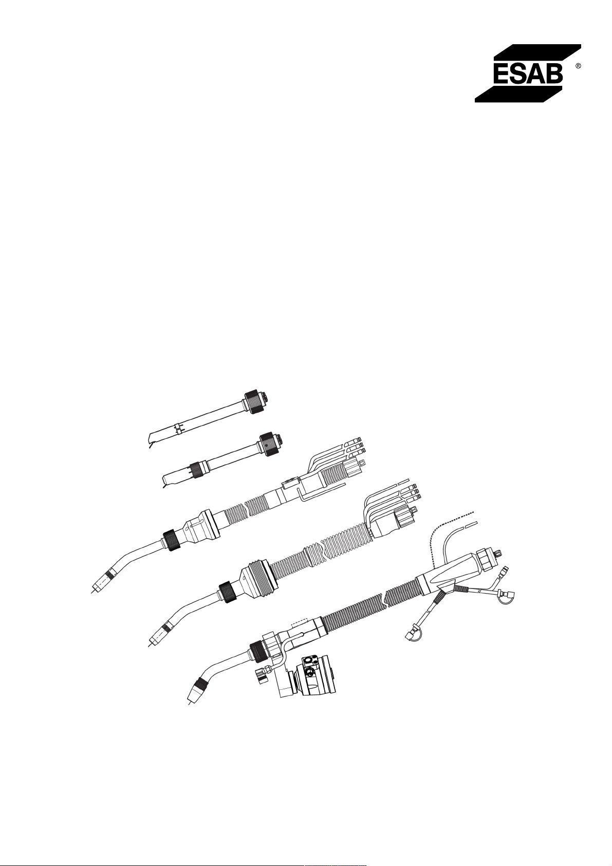
Az RT hegesztőpisztoly-rendszereket a teljes mértékben automatizált, hegesztőrobotokkal
végzett MIG/MAG hegesztéshez fejlesztették ki. A rendszer különböző, robotokhoz
használatos Aristo RT hegesztőpisztoly-nyakakat, hegesztőpisztoly-tartókat, robotokhoz
kialakított kábelszerelvényeket és olyan biztonsági leállító funkciókat tartalmaz, amelyek
megakadályozzák, hogy a rendszer összeütközzön valamivel és kár keletkezzen benne.
A hagyományos RT hegesztőrendszer egy RTKS-2 mechanikus, rugó működtetésű
biztonsági leállító mechanizmus révén ütközésvédelemmel van ellátva. Ez opcionálisan
lecserélhető egy RTFL-2 eszközre, amely kihasználja a robotvezérlő rendszer
ütközésérzékelő funkcióját. A hagyományos RT hegesztőrendszer számos különböző típusú
kábelszerelvénnyel használható.
Az Infiniturn vagy Helix kábelszerelvényekkel ellátott RTKSC-2 és RTFLC-2
hegesztőpisztoly-tartók az összetett hegesztési alkalmazásoknál alkalmazott üreges csuklójú
robotikus hegesztőrendszereknél használatosak. Az RTKSC-2 hegesztőpisztoly-tartónál
alkalmazott biztonsági leállító mechanizmus ütközés esetén lehetővé teszi a
hegesztőpisztoly nagyfokú elhajlását. Az Infiniturn és Helix kábelszerelvényeket egyszerű
beszerelni, és pontos manőverezési képességű, rendkívül megbízható rendszert
biztosítanak.
A népszerű és már bizonyított Aristo RT robotikus hegesztőpisztolyokkal ezek az összetevők
egy rendkívül megbízható, hosszan tartó és minimális karbantartást igénylő rendszert
alkotnak.
A hegesztőpisztoly-tartók és kábelszerelvények kiszállításakor azokhoz használati útmutatót
is mellékelünk.
Az ESAB rendelési számok és az elérhető tartozékok, pótalkatrészek és kopó
alkatrészek a Pótalkatrészjegyzékben találhatók.
0463 373 101
- 10 -
© ESAB AB 2018

3 BEVEZETÉS
3.1 A hegesztőpisztoly-rendszerek áttekintése
Hagyományos RT rendszer
Részletes leírásért tekintse meg a MŰSZAKI
ADATOK című rész megfelelő szakaszát:
1. Hegesztőpisztoly-nyak
Lásd: Hegesztőpisztoly.
2. Kábelszerelvény
Lásd: Kábelszerelvények
hagyományos RT rendszerhez.
3. Hegesztőpisztoly-tartó
Lásd: Hegesztőpisztoly-tartók
hagyományos RT rendszerhez.
4. RT KS-2 biztonsági leállító
mechanizmus
Lásd: RT KS-2 biztonsági leállító
mechanizmus.
5. RTFL-2 közbetét
Lásd: RTFL-2 közbetét.
6. Adapterközbetét (ha szükséges)
Lásd: Adapterközbetétek.
0463 373 101
- 11 -
© ESAB AB 2018

3 BEVEZETÉS
Üreges csuklójú rendszer
Részletes leírásért tekintse meg a MŰSZAKI
ADATOK című rész megfelelő szakaszát:
1. Hegesztőpisztoly-nyak
Lásd: Hegesztőpisztoly.
2. RTKSC-2 hegesztőpisztoly-tartó
Lásd: RT KSC-2
hegesztőpisztoly-tartó biztonsági
leállító mechanizmussal.
3. RTFLC-2 hegesztőpisztoly-tartó
Lásd: RTFLC-2 merev
hegesztőpisztoly-tartó.
4. Adapterközbetét
Lásd: Adapterközbetétek.
5. Helix vagy Infiniturn
kábelszerelvény
Lásd: Kábelszerelvények üreges
csuklójú rendszerekhez.
0463 373 101
- 12 -
© ESAB AB 2018

4 MŰSZAKI ADATOK
4 MŰSZAKI ADATOK
4.1 Hegesztőpisztoly-nyak
A hegesztőpisztoly típusát a hegesztési művelet alapján kell kiválasztani. Figyelembe kell
venni a működési ciklust és a teljesítményt, a hűtési módot és a huzal átmérőjét is. Ha
fokozott követelmények állnak fenn, például előre felhevült munkadarabok vagy nagy
hővisszaverődés a sarkokban, akkor ezeket figyelembe véve kell olyan hegesztőpisztolyt
választani, amelynek teljesítményjellemzői meghaladják a fokozott követelményeket.
Az RT hegesztőpisztolyokat a CE szabvány szerinti hegesztő-áramforrásokkal való
használatra tervezték, argon védőgázas fogyóelektródos ívhegesztéshez (MIG) és
szén-dioxid védőgázas fogyóelektródos ívhegesztéshez (MAG), valamint a
kereskedelemben kapható hengerelt forraszanyagokkal történő argon védőgázas
ívhegesztéshez. Ne használja a hegesztőpisztolyt más folyamathoz.
Acél és alumínium impulzusos ívhegesztéshez RT82W vízhűtéses hegesztőpisztolyt kell
használni.
Az elérhető hegesztőpisztoly-modellek lentebb láthatók.
Hegesztőpisztoly-
Hűtési mód Védőgáz Teljesítmény
modell
RT42G Gázhűtéses CO
Gázhűtéses 300A / 100%
Gázhűtéses Vegyes gáz 350A / 60%
Gázhűtéses 250A / 100%
RT42W Vízhűtéses CO
Vízhűtéses 420A / 100%
Vízhűtéses Vegyes gáz 350A / 60%
Vízhűtéses 350A / 100%
RT52G Gázhűtéses CO
Gázhűtéses 300A / 100%
Gázhűtéses Vegyes gáz 350A / 60%
Gázhűtéses 250A / 100%
RT52W Vízhűtéses CO
Vízhűtéses 470A / 100%
Vízhűtéses Vegyes gáz 400A / 60%
2
2
2
2
420A / 60%
420A / 60%
420A / 60%
470A / 60%
Vízhűtéses 400A / 100%
RT62G Gázhűtéses CO
Gázhűtéses 340A / 100%
Gázhűtéses Vegyes gáz 420A / 60%
Gázhűtéses 290A / 100%
RT62W Vízhűtéses CO
Vízhűtéses 530A / 100%
Vízhűtéses Vegyes gáz 450A / 60%
Vízhűtéses 450A / 100%
0463 373 101
- 13 -
2
2
500A / 60%
530A / 60%
© ESAB AB 2018

4 MŰSZAKI ADATOK
Hegesztőpisztoly-
Hűtési mód Védőgáz Teljesítmény
modell
RT72G Gázhűtéses CO
2
480A / 60%
Gázhűtéses 320A / 100%
Gázhűtéses Vegyes gáz 400A / 60%
Gázhűtéses 270A / 100%
RT72W Vízhűtéses CO
2
480A / 60%
Vízhűtéses 430A / 100%
Vízhűtéses Vegyes gáz 480A / 60%
Vízhűtéses 430A / 100%
RT82W Vízhűtéses CO
2
600A / 60%
Vízhűtéses 600A / 100%
Vízhűtéses Vegyes gáz 550A / 60%
Vízhűtéses 550A / 100%
A hegesztőpisztoly teljesítménye és működési ciklusa 10 perces ciklusra vonatkozik.
A műszaki adatok szabványos kopó-/pótalkatrészeket használó szabványos alkalmazásra
vonatkoznak. A hegesztőpisztoly teljesítménye fémátvitelű impulzusos ívhegesztés esetén
csökkentve lett.
Hőmérséklet-tartományok Tárolás: -15-50°C (5-122°F)
Üzemeltetés: 5–40°C (41–104°F)
Lefúvatógáz Max. 10 bar, külön gázcső
Össztömeg (hegesztőpisztoly-nyak,
Kb. 5kg
biztonsági leállító mechanizmus,
hegesztőpisztoly-tartó és 1 m
kábelszerelvény)
4.2 Feszültségi osztály
Max. megengedett
feszültség/áramerősség
Teljes hegesztőpisztoly-rendszer 141 V (csúcsérték hegesztéshez)
RTKS-2 biztonsági leállító vezérlőáramkör
RTKS-2 nyomógomb
RTKSC-2 biztonsági leállító vezérlőáramkör 48 V
Fúvókaérzékelő funkció használata esetén
hagyományos kábelszerelvénnyel
24 V / 1 A
48 V / 0,1 A
50 V / 5 A
(Megengedett terhelés max. 1 perc névleges
áramerősség mellett)
Fúvókaérzékelő funkció használata esetén
Helix vagy Infiniturn kábelszerelvénnyel
50 V / 5 A
(Megengedett terhelés max. 1 perc névleges
áramerősség mellett)
A feltüntetett besorolások szabványos felhasználás esetére vonatkoznak.
A kábelszerelvények besorolását lásd a „Kábelszerelvények” című részben.
0463 373 101
- 14 -
© ESAB AB 2018

4 MŰSZAKI ADATOK
4.2.1 Hűtőkörök határértékei
Csak vízhűtéses változat esetében.
Minimális vízátfolyás: 1,0 l/perc (1,1 quart/perc)
Min. víznyomás: 2,5 bar (36,3 psi)
Max. víznyomás: 3,5 bar (50,8 psi)
Bemenő hőmérséklet: max. 40 °C (104 °F)
Visszatérő hőmérséklet: max. 60 °C (140 °F)
Hűtőkapacitás: min. 1000 W, felhasználástól függően
VIGYÁZAT!
A 60 °C-nál (140 °F) magasabb visszatérő hőmérséklet károsíthatja vagy
tönkreteheti a kábelszerelvényt.
4.3 Hegesztőpisztoly-tartó
A szükséges hegesztőpisztoly-tartó az RT hegesztőpisztoly-rendszer kialakításától és az
alkalmazott biztonsági leállító eszközöktől függ (lásd „A hegesztőpisztoly-rendszerek
áttekintése” című fejezetet).
Alkatrész Körülbelüli tömeg
Hegesztőpisztoly-tartó (hagyományos
0,43 kg
rendszerhez)
RTKS-2 biztonsági leállító mechanizmus
0,85 kg
(hagyományos rendszerhez)
RTFL-2 közbetét (hagyományos
0,35 kg
rendszerhez)
RTKSC-2 hegesztőpisztoly-tartó (üreges
1,90 kg
csuklójú rendszerhez)
RTFLC-2 merev hegesztőpisztoly-tartó
1,22 kg
(üreges csuklójú rendszerhez)
Robotikus hegesztőpisztoly 0,66 kg
4.3.1 Hegesztőpisztoly-tartók hagyományos RT rendszerhez
Hagyományos RT rendszerek esetében a hegesztőpisztoly-tartó az RTKS-2 biztonsági
leállító mechanizmusra (vagy az RTFL-2 közbetétre) kerül felszerelése, összekötve a
kábelszerelvényt és a csatlakoztatott hegesztőpisztoly-nyakat.
A hegesztőpisztoly-tartót a hegesztőpisztoly típusa és annak geometriája alapján kell
kiválasztani. Különböző tartók használhatók. A hagyományos RT rendszerhez elérhető
hegesztőpisztoly-tartókat lásd a pótalkatrészjegyzékben.
0463 373 101
- 15 -
© ESAB AB 2018

4 MŰSZAKI ADATOK
Hegesztőpisztoly-tartó hagyományos karú robotokhoz
4.3.1.1 RT KS-2 biztonsági leállító mechanizmus
Az RT KS-2 biztonsági leállító mechanizmus egy rugó működtetésű eszköz, amely ütközés
esetén védi a robotot és a hegesztőrendszert.
MEGJEGYZÉS!
Az RT KS-2 eszközt ne szerelje szét.
4.3.1.2 RTFL-2 közbetét
Ha a robot rendelkezik elektronikus ütközésészlelő rendszerrel, akkor az RTKS-2 helyett
RTFL-2 merev közbetét is használható.
0463 373 101
- 16 -
© ESAB AB 2018

4 MŰSZAKI ADATOK
4.3.2 Hegesztőpisztoly-tartók üreges csuklójú rendszerhez
Üreges csuklójú rendszer esetében az Aristo RT hegesztőpisztoly-nyakat KSC-2 vagy FLC-2
hegesztőpisztoly-tartóhoz kell csatlakoztatni.
A RTKSC-2 hegesztőpisztoly-tartó ütközés esetén lehetővé teszi a hegesztőpisztoly
elhajlását. Ugyanakkor egy elektromos érintkező nyitása jelzi a robotvezérlő számára, hogy
álljon meg. A hiba elhárítása után a vezérlő a kiindulási geometriát és a hegesztőpisztoly
eszközközéppontját (TCP – Tool Center Point) nagy pontossággal állítja be. A rendszer
tisztán mechanikus elven működik és rugó működtetésű.
Az RTFLC-2 hegesztőpisztoly-tartó nem rendelkezik beépített biztonsági leállító funkcióval.
Üreges csuklójú rendszerek esetében ajánlott az RTKSC-2 G/W (alternatív megoldásként
RTFLC-2 G/W) hegesztőpisztoly-tartót alkalmazni. Ez a hegesztőpisztoly-tartó az Aristo RT
sorozat gázhűtéses és vízhűtéses hegesztőpisztolyaival is használható.
RTKSC-2 G/W RTFLC-2 G/W
A biztonsági leállító
Mechanikus n.a. (merev tartó)
mechanizmus működési
alapelve
Tengelyirányú bontási erő
650 N n.a. (merev tartó)
(Fz)
Keresztirányú bontási erő
24 Nm n.a. (merev tartó)
(Mx)
Visszaállás bontás után Automatikus n.a. (merev tartó)
Megismételhetőség Hagyományos Aristo RT
n.a. (merev tartó)
hegesztőpisztoly TCP-je ± 0,1
mm oldalirányba
Max. elhajlás Kb. ± 8° n.a. (merev tartó)
Biztonsági kapcsoló Alapállapotban zárt
n.a. (merev tartó)
Elektromos terhelés: max. 48
V / 1A
0463 373 101
- 17 -
© ESAB AB 2018
4 MŰSZAKI ADATOK
Fúvókaérzékelő funkció
elektromos vezérlőáramköre
Besorolás:
• Helix kábelszerelvények
esetén: max. 50 V DC /
5 A, max. 1 perc
Érintkezés érzékelése
esetén gyorsan
megszünteti az
érzékelési feszültséget.
• Infiniturn
kábelszerelvények
esetén a fúvókaérzékelő
funkció korlátozott. Az
alkalmazásához
elérhető lehetséges
megoldásokkal
kapcsolatban vegye fel
a kapcsolatot az ESAB
vállalattal.
Feszültségi osztály A biztonsági leállító áramkör
maximálisan megengedett
feszültsége: 48 V.
Besorolás:
• Helix kábelszerelvények
esetén: max. 50 V DC /
5 A, max. 1 perc
• Infiniturn
kábelszerelvények
esetén: max. 50 V DC /
1 A, max. 1 perc
Érintkezés érzékelése esetén
gyorsan megszünteti az
érzékelési feszültséget.
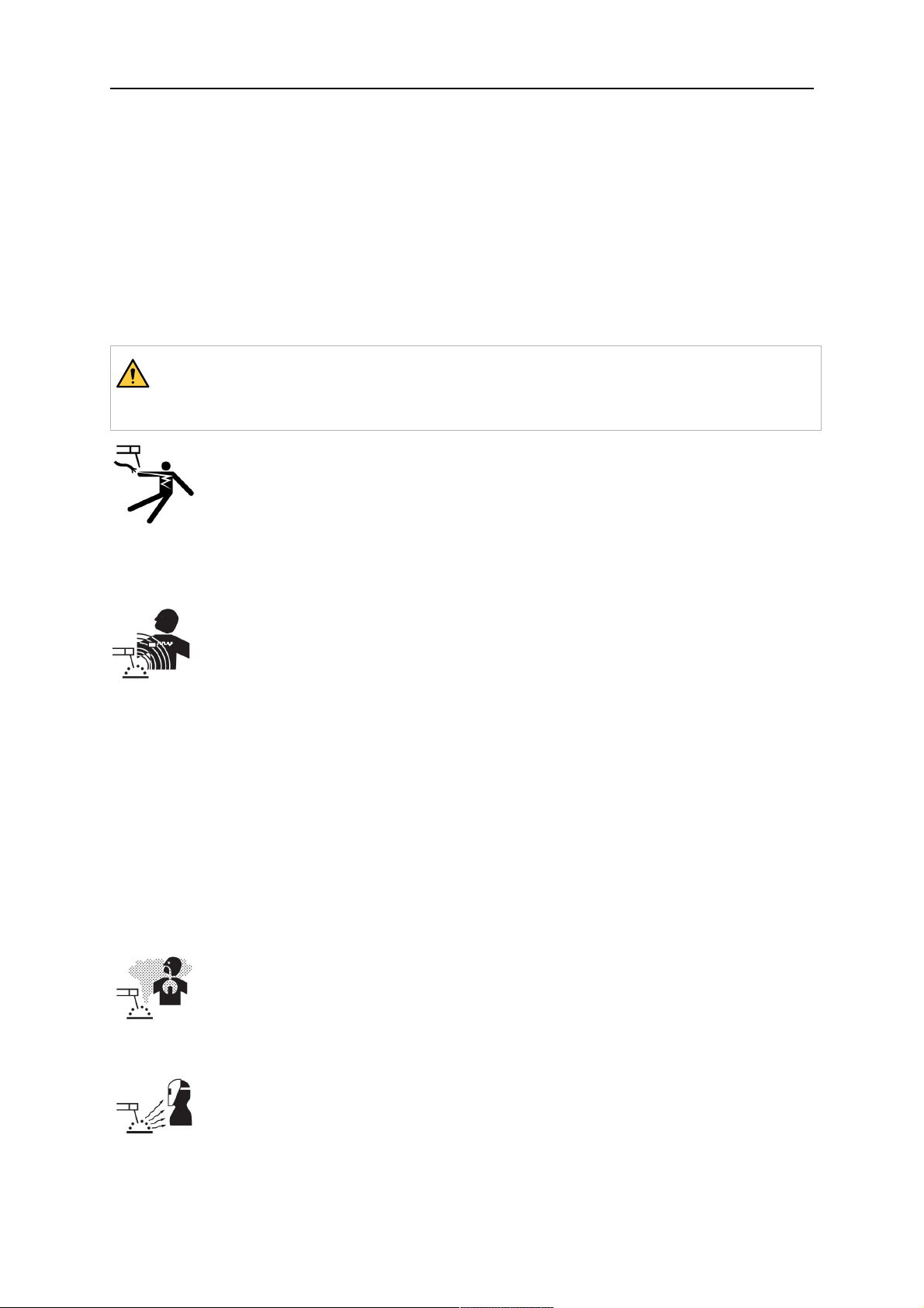
4.3.2.1 RTKSC-2 G/W hegesztőpisztoly-tartó biztonsági leállító mechanizmussal
Tétel Leírás Funkció
1 Hegesztőpisztoly-nyak
Aristo RT hegesztőpisztoly interfész
támaszték
2 RTKSC-2 burkolata Szerelvény kábel- és hegesztőpisztoly interfésszel
0463 373 101
- 18 -
© ESAB AB 2018

4 MŰSZAKI ADATOK
Tétel Leírás Funkció
3 Gumiütköző Biztonsági leállító mechanizmus védelme
4 RTKSC-2 főrésze Ütközés esetén lehetővé teszi a pisztoly elhajlását
5 Adapterközbetét Elválasztóinterfész a robotcsuklóhoz (az adott
robottípushoz illeszkedik)
6 Jelzőcsap Az adapterközbetét pontos beállításához
7 Vezérlőkábel-csatlakozó Az ütközésjelet és a fúvókaérzékelő funkció jelét
továbbító elektromos csatlakozás
8 Mikrokapcsoló Ütközésérzékelő
4.3.2.2 RTFLC-2 G/W merev hegesztőpisztoly-tartó
Tétel Leírás Funkció
1 Hegesztőpisztoly-nyak
Aristo RT hegesztőpisztoly interfész
támaszték
2 RTFLC-2 burkolata Szerelvény kábel- és hegesztőpisztoly interfésszel
3 RTFLC-2 főrésze Ütközés esetén lehetővé teszi a pisztoly elhajlását
4 Jelzőcsap Az adapterközbetét pontos beállításához
5 Adapterközbetét Elválasztóinterfész a robotcsuklóhoz (az adott
robottípushoz illeszkedik)
6 Vezérlőkábel-csatlakozó (3
pólusú)
0463 373 101
A fúvókaérzékelő funkció jelét (ha van) továbbító
elektromos csatlakozás
- 19 -
© ESAB AB 2018
4 MŰSZAKI ADATOK
4.4 Adapterközbetétek
A robot típusától függően válassza ki a robotkarra felszerelendő adapterközbetétet.
Adapterközbetétek a hagyományos és üreges csuklójú rendszerekhez is elérhetők (lásd a
pótalkatrészjegyzéket).
4.5 Kábelszerelvények
A huzalelőtoló csatlakozását a kábelszerelvény típusa határozza meg. Az alkalmazható
változatok a rendszer kialakításától és a hűtőközegtől (gáz- vagy vízhűtés) függnek (lásd a
pótalkatrészjegyzéket).
A teljesítmények 1 m-től 5 m-ig terjedő kábelhossz esetén érvényesek.
Hagyományos
Infiniturn Helix
kábelszerelvény
Teljesítmény (10
perces ciklus)
Gázhűtéses (vegyes
gáz)
Teljesítmény (10
perces ciklus)
Max. 500 A / 60 %-os
működési ciklus
Max. 350 A / 100
%-os működési ciklus
Max. 600 A / 100
%-os működési ciklus
Max. 400 A / 60 %-os
működési ciklus
Max. 320 A / 100
%-os működési ciklus
Max. 550 A / 100
%-os működési ciklus
Max. 400 A / 60 %-os
működési ciklus
Max. 320 A / 100
%-os működési ciklus
Max. 550 A / 100
%-os működési ciklus
Vízhűtéses
Forgási tartomány Korlátozott Korlátlan A kiindulási
helyzethez képest ±
270°
Tömeg
Gázhűtéses
Tömeg
Vízhűtéses
1,2 m-es hosszúság:
2,35 kg
1,2 m-es hosszúság:
2,35 kg
1,0 m-es hosszúság:
2,0 kg
1,0 m-es hosszúság:
2,0 kg
1,0 m-es hosszúság:
2,0 kg
1,0 m-es hosszúság:
2,0 kg
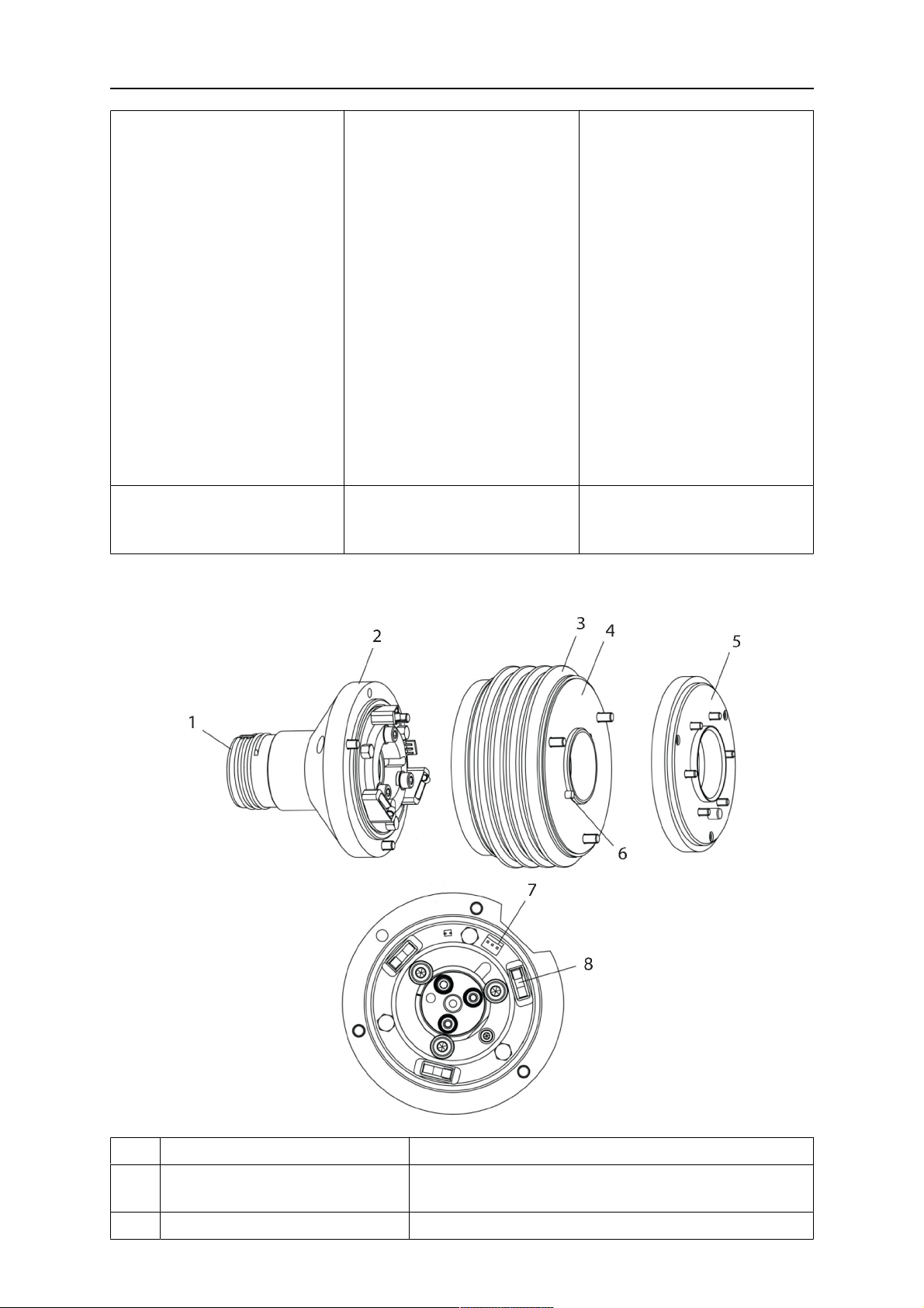
4.5.1 Kábelszerelvények hagyományos RT rendszerhez
0463 373 101
- 20 -
© ESAB AB 2018

4 MŰSZAKI ADATOK
Burndy csatlakozótűk
A. Gázfúvóka
érintésérzékelője
C. Ütközésérzékelő
F. 0V
G. + motorfeszültség
H. - motorfeszültség
D. Ütközésérzékelő
E. Befűzés
Tétel Leírás Funkció
1 Nyaktámasztó közbetét Hegesztőpisztoly-interfész
2 Védőburkolat Megvédi a kábelszerelvényt a sérülésektől
3 Burndy csatlakozó, 12 pólusú A biztonsági leállító eszköz és a huzalelőtoló közötti
elektromos csatlakozás
4 Vezérlőkábel KS-2 esetén (biztonsági leállító funkció és
nyomógomb)
5 EURO csatlakozó Huzalelőtoló csatlakozása
6 Lefúvatócső (fekete kupak) A hegesztőpisztoly sűrített levegővel történő
tisztításához a tisztítási ciklus után
7 Vízbement (kék kupak)
Vízbement a hegesztőpisztoly hűtéséhez
1)
8 Vízvisszaáramlás (piros kupak) A felmelegedett víznek a hegesztőpisztolytól való
elvezetésére szolgál
9 A biztonsági leállító
mechanizmus vezérlőkábelének
csatlakozója
1)
Csak vízhűtéses hegesztőpisztolyok esetében
Elektromos csatlakozó az RTKS-2 eszközhöz a
biztonsági leállítás jelének és a fúvókaérzékelő
funkció jelének a továbbításához
1)
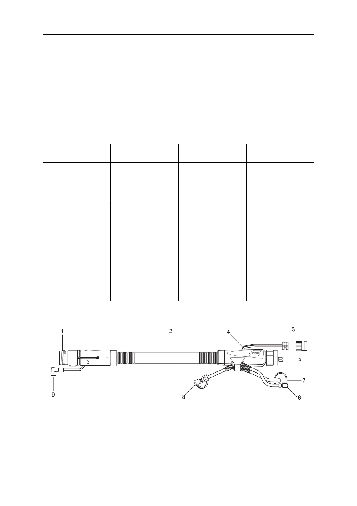
4.5.2 Kábelszerelvények üreges csuklójú rendszerekhez
Az Infiniturn kábelszerelvény használata esetén a hegesztőpisztoly mindkét irányba
akadálymentesen körbeforoghat. Ugyanakkor továbbítja a hűtőfolyadékot, a védőgázt, a
lefúvatógázt, a hegesztőáramot és a biztonsági leállító mechanizmus jelét.
A Helix kábelszerelvény használata esetén a hegesztőpisztoly a kiindulási helyzethez képest
mindkét irányba 270°-ban tud elfordulni. Olyan hegesztési feladatokhoz használható,
amelyek nem igényelnek akadálymentes körbeforgást.
Az Infiniturn kábelszerelvény gáz- vagy vízhűtés változatban is elérhető. A Helix
kábelszerelvény gáz- vagy vízhűtés alkalmazásokhoz is használható.
MEGJEGYZÉS!
A gázhűtéses hegesztőpisztoly-nyakkal működő Helix kábelt ne csatlakoztassa
vízhűtéses rendszerhez.
0463 373 101
- 21 -
© ESAB AB 2018

4 MŰSZAKI ADATOK
Tétel Leírás Funkció
1 Közbetét RTKSC-2 / RTFLC-2 hegesztőpisztoly-tartó
interfész
2 Jelzőcsap Biztosítja a megfelelő csatlakoztatási irányt
3 Vezérlőkábel csatlakozója Elektromos csatlakozó az RTKSC-2 eszközhöz a
biztonsági leállítás jelének és a fúvókaérzékelő
funkció (ha van) jelének a továbbításához
4 EURO csatlakozó Huzalelőtoló csatlakozása
5 Vezérlőkábel Elektromos csatlakozó a biztonsági leállítás jelének
(az RTKSC-2 eszköztől) és a fúvókaérzékelő
funkció jelének a továbbításához (a fúvókaérzékelés
a Helix kábelszerelvényen alapfelszereltség, de az
Infiniturn kábelszerelvényen nem)
6 Vízvisszaáramlás (piros kupak) A felmelegedett víznek a hegesztőpisztolytól való
elvezetésére szolgál
7 Vízbement (kék kupak) Vízbement a hegesztőpisztoly hűtéséhez
8 Lefúvatócső (fekete kupak) Hegesztés utáni magas nyomású levegővel való
tisztításhoz
9 Közegcsatlakozó Akadálymentesen körbeforduló csatlakozás
közegtovábbítással
10 Védőburkolat Megvédi a kábelszerelvényt a sérülésektől
0463 373 101
- 22 -
© ESAB AB 2018

5 INSTALLATION
5 INSTALLATION
FIGYELMEZTETÉS!
For your own safety, make sure that the robot is either in standby or power-less
state before doing maintenance work in the moving radius of the robot.
Follow the assembly instructions exactly. Pay attention during assembly that the cables are
not damaged. Damaged cables can lead to a short circuit, which may damage the electronics
of the robot or the welding torch.
Use only original ESAB components that have been specially developed for this purpose.
Only then the correct functioning of the whole welding torch system can be guaranteed.
5.1 RTKS-2 standard arm installation
5.1.1 RTKS-2 safety-off mechanism
1. Dismount the insulation flange (10) from the RTKS-2 (11) by removing the screws
(12).
2. Position the insulation flange (10) with the index pin on the robot arm and fix it with the
screws (20) included.
The insulation flange (10) is directly compatible with robots with tool flange according
to DIN ISO 9409-1-A40 (diameter 40mm, 4×M6). If the insulation flange (10) does
not fit, use an adapter flange (21).
MEGJEGYZÉS!
Ensure that the index pin is located correctly. The maximum torque of 1.2Nm
(10.5in.lb) must be observed for the fastening of the adapter flange screws.
Prevent self-loosening of the screws by using suitable thread locking
measures.
3. Mount the RTKS-2 the back on the insulation flange (10).
0463 373 101
- 23 -
© ESAB AB 2018

5 INSTALLATION
4. Position the mount on the RTKS-2 and carefully insert the cylindrical pins (14) into the
holes provided. Take the position of the torch into account. Two mounting positions
may be potentially possible.
5. Screw the mount evenly using the enclosed cylinder screws with hexagon socket (12).
MEGJEGYZÉS!
The maximum tightening torque for the cylinder screw (5) is 6Nm (53in.lb)
and the property class category is 8.8.
12 - Cylinder screw with hexagon socket
M6DIN912 (length of the screw depending
on the torch mount)
14 - Cylindrical pins Ø4×20
5.1.1.1 Torch installation with adjustable mount
Torch mounts with a central clamping assembly can only be fastened on the journal of the
mounting flange. For this, the mounting flange must be fastened first.
1. If applicable, carefully press the cylindrical pins (1) into the corresponding holes in the
mounting flange. The pins should protrude by approximately 5 mm (0.2 in.).
2. Position the mount on the safety-off mechanism RTKS-2 and carefully insert the
cylindrical pins (1) into the holes provided. In doing so, take the later position of the
torch into account. Two mounting positions may be potentially possible.
3. Then screw down the mounting flange evenly using the enclosed cylinder screws with
hexagon socket (2).
MEGJEGYZÉS!
The maximum tightening torque for the cylinder screw (2) is 7.1 Nm (62.8
in.lb) and the property class category is 8.8.
0463 373 101
- 24 -
© ESAB AB 2018

5 INSTALLATION
4. Unscrew the axial cylinder screw with hexagon socket (4) out of the mounting flange
together with the washer (3).
1 - Cylindrical pins Ø4×14 3 - Washer Ø9 mm
2 - Cylinder screw with hexagon socket
M6×16
4 - Axial cylinder screw with hexagon
socket M8×16
5. Place the torch mount (5) onto the journal (6) of the mounting flange, paying attention
while doing so to the exact alignment of the feather key (7) and the corresponding
groove (7a).
6. Insert the clamping mandrel (8) into the lateral hole (see illustration) and position it so
that the mating surfaces (9a) of the clamping mandrel rest on the mating surface (9) of
the journal.
0463 373 101
- 25 -
© ESAB AB 2018

5 INSTALLATION
7. Fix the clamping mandrel from the opposite side using the M6 cylinder screw with
hexagon socket (10) and the Ø22 mm washer (11).
8. Screw the axial cylinder screw (4) with the Ø9 mm washer (3) into the mounting flange
and tighten firmly.
3 - Washer Ø9 mm 8 - Clamping mandrel
4 - Axial cylinder screw with hexagon
9 - Mating surface of mounting flange
socket M8×16
5 - Torch mount 9a - Mating surfaces of clamping mandrel
6 - Mounting flange journal 10 - Cylinder screw with hexagon socket
M6×30
7 Feather key 11 - Washer Ø22×6.4 mm
7a - Groove for feather key
5.1.2 Standard arm cable assembly for KS-2 and FL-2
The cable assembly must be aligned to the intended use in length and design. The type of
cooling for the torch and the cable assembly must be the same (either gas or water cooled
respectively). In order to prevent damage to the torch system and other components, it is
imperative to observe the following instructions.
0463 373 101
- 26 -
© ESAB AB 2018

5 INSTALLATION
VIGYÁZAT!
• Coordinate the length and design of the cable assembly to suit the range of
action of the robot.
• Do not bend, compress or overstretch the cable assembly.
• Fix the cable assembly such that is can be moved freely and cannot become
entangled.
• Any additional holding devices possibly installed, for example a balancer,
must not crush or bend the cable assembly.
• Extreme turning movements must be avoided in which the cable assembly
may become twisted.
• Chafing on the robot or other objects must be excluded.
1. Unscrew the cylinder screws (1) and lift off the top section (2) of the torch mount.
2. Insert the feather key (4) into the recess of the neck support flange (3) from below.
3. Align the neck support flange (3) including the feather key (4) to the groove (5) of the
torch mount and push into the groove right up to the stop of the flange.
4. Hold the cable assembly in this position and simultaneously place the top section (2)
back onto the torch mount. First screw both cylinder screws (1) loosely in to about the
same length, then tighten alternately. The top section (2) of the mount should have an
even gap to the bottom section.
The front part of the cable assembly is directly clamped into the torch mount (see
illustration below).
1 - Cylinder screws 4 - Feather key
2 - Torch mount top section 5 - Groove for feather key
3 - Neck support flange
5.1.3 RTKS-2 wire feeder connection
In order to be able to create the connection, the cable assembly must be mounted as
described in the "Installing the cable assembly" section and equipped following "Installing the
wire guide" section. Only then can the central and media connection take place. Proceed as
described below:
0463 373 101
- 27 -
© ESAB AB 2018

5 INSTALLATION
1. Connect the central connector of the cable assembly (2) to the wire feeder cabinet
socket. Tighten the central connector sleeve nut fingertight. Do not use tools.
1 - Burndy Connector 4 - Return of heated water (red cap)
2 - EURO central connector 5 - Return of heated water (red cap)
3 - Air blow-out 6 - Main Wire feeder
2. For water cooled systems. Connect the water hoses to the cooling circuit. The end of
the hose marked blue (4) is connected to the water outlet, and the end marked red (5)
is connected to the water return.
3. Connect the blow-out line (3) to the corresponding connection of the feeder.
4. Connect the Burndy Connector to the wire feeder. (1) to the feeder. See section
"Electrical connections".
MEGJEGYZÉS!
All hoses and the control line must be installed so they can not bend or get
damaged!
5.1.4 RTKS-2 electrical connections
5.1.4.1 RTKS-2 safety-off mechanism connection
The switch for the safety-off functionality RTKS-2 is connected through the control cable,
see (3) in the illustration below. This connects to the RTKS-2 unit via the 4-pole plug (4) that
contains circuits for the push-button (6) and the safety-off signal (7).
If a collision is detected, the control circuit for the safety-off signal (7), which is normally
closed, will be interrupted.
Rating of the control circuit: max. 48 V / 1 A
0463 373 101
- 28 -
© ESAB AB 2018

5 INSTALLATION
2 - Burndy connector 5 - RTKS-2 connector for control cable plug
4 - Control cable plug
Burndy csatlakozótűk
A. Gázfúvóka
érintésérzékelője
C. Ütközésérzékelő
F. 0V
G. + motorfeszültség
H. - motorfeszültség
D. Ütközésérzékelő
E. Befűzés
If the robot control provides a control circuit for nozzle sense functionality, the connection is
accomplished with a 1-wire connection.
Rating of the control circuit: max 50 V / 5 A.
VESZÉLY!
If the nozzle sense function is not being used, the open end of the control cable on
the power source connection side must be properly isolated in order to avoid short
circuits. During certain problems on the torch head, the full welding potential may be
present on this cable.
VIGYÁZAT!
After detection of contact (gas nozzle on work piece), quickly reduce or cut off the
maximum current in the nozzle sense circuit in order to avoid overloading of the
system.
Allowed load max. 1 minute at the rated nominal current.
5.1.5 RTKS-2 Torch installation
Continue according to section "Torch installation".
0463 373 101
- 29 -
© ESAB AB 2018

5 INSTALLATION
5.2 RTFL-2 standard arm installation
5.2.1 RTFL-2 rigid mount
1. Position the RT FL-2 (2) with the index pin on the robot arm and fix it with the hexagon
socket screw included.
The FL-2 is directly compatible with robots with tool flange according to DIN ISO
9409-1-A40 (diameter 40mm, 4×M6). If the rigid mount does not fit, use an adapter
flange (3).
MEGJEGYZÉS!
Ensure that the index pin is located correctly. The maximum torque of 1.2Nm
(10.5in.lb) must be observed for the fastening of the adapter flange screws.
Prevent self-loosening of the screws by using suitable thread locking
measures.
2. Install torch mount (1). Only torch mounts having a hole pattern equivalent with the
mounting surface may be attached. If necessary, carefully press the cylindrical pins (4)
into the corresponding holes in the bracket. The pins should protrude by
approximately 5mm (0.2in.). Position the torch mount on the RTFL-2 (2) and
carefully insert the cylindrical pins (4) into the holes provided. Take the position of the
torch into account. Two mounting positions may be potentially possible.
3. Screw the mount evenly using the enclosed cylinder screws with hexagon socket (5).
MEGJEGYZÉS!
The maximum tightening torque for the cylinder screw (5) is 6Nm (53in.lb)
and the property class category is 8.8.
0463 373 101
- 30 -
© ESAB AB 2018

5 INSTALLATION
4 - Cylindrical pins Ø4×20
5 - Cylinder screw with hexagon socket M6
DIN 912 (length of the screw depending on
the torch mount)
Side view
Torch installation with adjustable mount
Torch mounts with a central clamping assembly can only be fastened on the journal of the
mounting flange. For this, the mounting flange must be fastened first.
1. If applicable, carefully press the cylindrical pins (1) into the corresponding holes in the
mounting flange. Avoid the formation of burrs. The pins should protrude by
approximately 5 mm (0.2 in.).
2. Position the mount on the RTFL-2 and carefully insert the cylindrical pins (1) into the
holes provided. In doing so, take the later position of the torch into account. Two
mounting positions may be potentially possible.
3. Then screw down the mounting flange evenly using the enclosed cylinder screws with
hexagon socket (2).
MEGJEGYZÉS!
The maximum tightening torque for the cylinder screw (2) is 7.1 Nm (62.8
in.lb) and the property class category is 8.8.
4. Unscrew the axial cylinder screw with hexagon socket (4) out of the mounting flange
together with the washer (3).
1 - Cylindrical pins Ø4×14 3 - Washer Ø9 mm
2 - Cylinder screw with hexagon socket
M6×16
4 - Axial cylinder screw with hexagon
socket M8×16
5. Place the torch mount (5) onto the journal (6) of the mounting flange, paying attention
while doing so to the exact alignment of the feather key (7) and the corresponding
groove (7a).
0463 373 101
- 31 -
© ESAB AB 2018

5 INSTALLATION
6. Insert the clamping mandrel (8) into the lateral hole (see illustration) and position it so
that the mating surfaces (9a) of the clamping mandrel rest on the mating surface (9) of
the journal.
7. Fix the clamping mandrel from the opposite side using the M6 cylinder screw with
hexagon socket (10) and the Ø22 mm washer (11).
8. Screw the axial cylinder screw (4) with the Ø9 mm washer (3) into the mounting flange
and tighten firmly.
3 - Washer Ø9 mm 8 - Clamping mandrel
4 - Axial cylinder screw with hexagon
9 - Mating surface of mounting flange
socket M8×16
5 - Torch mount 9a - Mating surfaces of clamping mandrel
6 - Mounting flange journal 10 - Cylinder screw with hexagon socket
M6×30
7 - Feather key 11 - Washer Ø22×6.4 mm
7a - Groove for feather key
5.2.2 RTFL-2 torch installation
Continue according to section "Torch installation".
5.3 RTKSC-2 hollow wrist system installation
5.3.1 RTKSC-2 mount with safety off mechanism
VIGYÁZAT!
For hollow wrist systems make sure that the clear space around the robot is at least
Ø45 mm (1.8 in.) around the wrist and 50 mm (2.0 in.) near the wire feeder.
0463 373 101
- 32 -
© ESAB AB 2018

5 INSTALLATION
1. Remove the three screws (2) from the front cover (3) of the torch mount and carefully
pull the cover off the RTKSC-2 main body (5). Take care not to damage the micro
switches installed inside the assembly.
1 - Hexagon wrench 4 mm 4 - Rubber boot
2 - 3× M5×12 screws 5 - RT KSC-2 main body
3 - RT KSC-2 front cover
1. Pull off the rubber boot (4) from the RTKSC-2 main body (5) to the front.
2. Now position the RTKSC-2 main body (5) on the adapter flange (7) so that the index
pin is correctly seated. Attach with the screws (6) enclosed.
3. Reinstall the rubber boot (4) on the RTKSC-2 main body (5) and make sure it is
correctly located in the grooves on the front and back flange.
4. Istall the adapter flange (7) on the robot.
Fastening torque max. 2.2 Nm (19.5 in.lb).
1 - Hexagon wrench 4 mm 3 - 3× M5×12 hexagon socket screws
2 - Rubber boot 4 - Adapter flange
5.3.2 Mounting the cable assembly
MEGJEGYZÉS!
In order to adjust the wire feeder position to the cable assembly length, it must be
mounted on an adjustable support with a possible movement of ±2-3cm (±1in.) to
the back and to the front. The length of the cable assembly must be determined
from the centred mounting position of the wire feeder.
1. Move the robot arm into a completely straight position, see illustration below. Make
sure that (1) axis 6 (rotation around the torch axis) is in 0° position.
2. Move the feeder (3) completely to the back in order to create space for inserting the
cable assembly. If it is not possible to move the feeder sufficiently, it should be
removed from the robot.
0463 373 101
- 33 -
© ESAB AB 2018

5 INSTALLATION
3. Insert the cable assembly with the coupling (2) first into the robot arm and feed it
through the robot wrist.
4. The feeder should only be installed again after the correct mounting position with
respect to the cable length has been determined. (See section "Installing the cable
assembly").
VIGYÁZAT!
Axis 6 must be in 0° position.
5.3.2.1 RTKSC-2 feeder cabinet connections
When installed for the first time, the position of the wire feeder cabinet must be adjusted to
the length of the cable assembly. First, the robot arm must be fully extended (straight).
VIGYÁZAT!
As long as the correct position of the feeder corresponding to the length of the cable
assembly has not been determined, be careful when moving the robot arm and
avoid overstretching the cable. It is helpful to loosen the positioning screws of the
feeder before moving the robot arm to allow the feeder to follow the cable assembly.
0463 373 101
- 34 -
© ESAB AB 2018

5 INSTALLATION
1. Loosen the sliding mechanism of the wire feeder and connect the cable assembly.
2. Now adjust the position of the wire feeder to suit the length of the Infiniturn or Helix
cable, as indicated with "A" in the illustration below.
VIGYÁZAT!
When adjusting the position of the feeder cabinet, make sure that the cable
assembly is not under stress when the robot arm is in stretched-out position.
It is normal for the cable assembly to sag slightly, it should never be taut.
3. Before securing the wire feeder in its permanent position, ensure that the Euro
connectors are tightly connected. Then turn the torch mount down and up again
(rotating on the axis 5), in order not to tighten the cable assembly too much against
the feeder (see illustration above). Once this is done, tighten the feeder in that
position.
4. For water cooled systems, connect the water lines to the cooling circuit. See section
"Cable assemblies for hollow wrist systems" in the TECHNICAL DATA chapter for
indications.
The hose with the blue rubber cap is for cooling water to the torch, the hose with the
red rubber cap returns the heated water. Make sure the hoses will not kink or get
otherwise blocked.
MEGJEGYZÉS!
A Helix cable assembly used for a gas cooled system must not be connected
to a cooling circuit. As the water connections are not needed, they may be cut
off.
5. Connect the blow-out hose (black rubber cap) to the corresponding outlet of the wire
feeder.
MEGJEGYZÉS!
If the blow-out function is not used, the blow-out hose must be sealed with the
rubber cap enclosed. With Infiniturn systems, the blow-out air must be
supplied to the corresponding connection hose, if it is not permitted to connect
blow-out air to the shield gas connection!
6. Install the necessary plug on the control cable and connect it to the safety off circuit
interface of the wire feeder (see section "Electrical connections").
0463 373 101
- 35 -
© ESAB AB 2018

5 INSTALLATION
5.3.3 RTKSC-2 cable assembly
The cable assembly must be aligned to the intended use in length and design. The type of
cooling for the torch and the cable assembly must be the same (either gas or water cooled
respectively). In order to prevent damage to the torch system and other components, it is
imperative to observe the following instructions.
VIGYÁZAT!
• Coordinate the length and design of the cable assembly to suit the range of
action of the robot.
• Do not bend, compress or overstretch the cable assembly.
• Fix the cable assembly such that is can be moved freely and cannot become
entangled.
• Any additional holding devices possibly installed, for example a balancer,
must not crush or bend the cable assembly.
• Extreme turning movements must be avoided in which the cable assembly
may become twisted.
• Chafing on the robot or other objects must be excluded.
5.3.3.1 RTKSC-2 cable assembly installation
MEGJEGYZÉS!
For some robots, it may be possible to deviate from this order, and first connect the
cable assembly to the RTKSC-2, then thread the cable from the front through the
robot arm. If in doubt, follow the suggested order.
1. Loosen the three screws (7) with the associated washers and remove them from the
RTKSC-2 cover (1). See illustration below.
2. Install the supplied O-rings (4) into the grooves in the cover (1).
3. Pull the cable assembly approximately 15 cm (6 in.) from the main body (3).
0463 373 101
- 36 -
© ESAB AB 2018

5 INSTALLATION
4. Insert the coupling (2) into the socket of the cover (1) as shown. Align the index pin (6)
with the index hole (5) in the main body and insert completely.
MEGJEGYZÉS!
Make sure that the position of the O-rings are not shifted by the index pin
during the assembly.
1 - RTKSC-2 cover 5 - Index hole
2 - Coupling 6 - Index pin
3 - RTKSC-2 main body 7 - 3× M5×35 screws
4 - 3× O-ring for water cooled systems 11 - Control cable connector
5. Insert the three screws (7) with the associated washers (8) and tighten gently with the
enclosed hexagonal wrench, see below illustration.
Fastening torque approximately 2 Nm (18 in.lb).
0463 373 101
- 37 -
© ESAB AB 2018

5 INSTALLATION
6. If present, insert the control cable plug (10) into the connector (11) and make sure it is
firmly seated.
7 - 3× M5×35 screw 11 - Control cable connector
8 - Washer 12 - 2× Micro switch
10 - Control cable plug 13 - Index pin
7. Gently push back the cable assembly into the robot arm and carefully seat the
RTKSC-2 cover (1) in place. Observe the index pin (13) to be in the correct position.
Make sure the two micro switches (12) are not damaged if present.
8. Insert the three M5 screws (14) and tighten without excessive force.
13. Index pin
14. 3× M5×12 screws
0463 373 101
- 38 -
© ESAB AB 2018

5 INSTALLATION
5.3.3.2 RTKSC-2 electrical connections
MEGJEGYZÉS!
After connecting the control cable, secure the cable in order to protect it from getting
caught while the robot is moving.
Usually, the control cable will be directly connected to the wire feeder. See the
manufacturer's documentation for details. The link to the robot control is then
implemented via the power source controller.
RTKSC-2 safety-off mechanism connection
The switch for the safety-off functionality RTKSC-2 is connected through the control cable,
see (3) in the illustration below. This connects to the RTKSC-2 unit via the control cable plug
(1).
The safety-off signal requires a 2-wire connection (black/black) to the safety-off circuit in the
robot control (5).
If a collision is detected, the control circuit (normally closed) will be interrupted (4).
Rating of the control circuit: max. 48 V / 1 A.
1 - Control cable plug 3 - Burndy connector VVV
2 - EURO central connector
Burndy csatlakozótűk
A. Gázfúvóka
érintésérzékelője
C. Ütközésérzékelő
F. 0V
G. + motorfeszültség
H. - motorfeszültség
D. Ütközésérzékelő
E. Befűzés
RTKSC-2 nozzle sense function connection
If the robot control provides a control circuit for nozzle sense functionality.
The connection is accomplished with a 2-wire connection (black/black) to the nozzle sense
circuit in the robot control (5), see illustration below.
0463 373 101
- 39 -
© ESAB AB 2018

5 INSTALLATION
Usually, the control cable will be directly connected to the wire feeder. See the
manufacturer's documentation for details. The link to the robot control is then implemented
via the power source robot interface.
Rating of the control circuit: max. 50 V / 5 A.
VESZÉLY!
If the nozzle sense function is not being used, the open end of the control cable on
the power source connection side must be properly isolated in order to avoid short
circuits. During certain problems on the torch head, the full welding potential may be
present on this cable.
VIGYÁZAT!
After detection of contact (gas nozzle on work piece), quickly reduce or cut off the
maximum current in the nozzle sense circuit in order to avoid overloading of the
system.
Allowed load max. 1 minute at the rated nominal current.
1 - Control cable plug 3 - Control cable
2 - EURO central connector
5.3.4 RTKSC-2 torch installation
Continue according to section "Torch installation".
0463 373 101
- 40 -
© ESAB AB 2018

5 INSTALLATION
5.4 RTFLC-2 installation
5.4.1 RTFLC-2 mount
1. Remove the three M5 screws (2) from the front cover (3) of the RT FLC-2 torch mount
and carefully pull the cover off the main body (4).
1 - Hexagon wrench 4 mm 3 - RT FLC-2 front cover
2 - 3× M5×12 screws 4 - RT FLC-2 main body
2. Now position the RT FLC-2 main body (4) on the adapter flange (6) so that the index
pin is correctly seated. Attach with the screws (5) enclosed
Fastening torque max. 2.2 Nm (19.5 in.lb).
1 - Hexagon wrench 4 mm 5 - 3× M5×12 hexagon socket screws
4 - RT FLC-2 main body 6 - Adapter flange
5.4.2 RTFLC-2 wire feeder connection
5.4.2.1 Feeding through the robot arm
MEGJEGYZÉS!
In order to adjust the wire feeder position to the cable assembly length, it must be
mounted on an adjustable support with a possible movement of ± 2-3 cm (± 1 in.) to
the back and to the front. The length of the cable assembly must be determined
from the centred mounting position of the wire feeder.
0463 373 101
- 41 -
© ESAB AB 2018

5 INSTALLATION
1. Move the robot arm into a completely straight position, see illustration below. Make
sure that (1) axis 6 (rotation around the torch axis) is in 0° position.
2. Move the feeder (3) completely to the back in order to create space for inserting the
cable assembly. If it is not possible to move the feeder sufficiently, it should be
removed from the robot.
3. Insert the cable assembly with the coupling (2) first into the robot arm and feed it
through the robot wrist.
4. The feeder should only be installed again after the correct mounting position with
respect to the cable length has been determined. (See section "Installing the cable
assembly").
VIGYÁZAT!
Important! Axis 6 must be in 0° position.
5.4.2.2 RTFLC-2 feeder cabinet connections
When installed for the first time, the position of the wire feeder cabinet must be adjusted to
the length of the cable assembly. First, the robot arm must be fully extended (straight).
VIGYÁZAT!
As long as the correct position of the feeder corresponding to the length of the cable
assembly has not been determined, be careful when moving the robot arm and
avoid overstretching the cable. It is helpful to loosen the positioning screws of the
feeder before moving the robot arm to allow the feeder to follow the cable assembly.
0463 373 101
- 42 -
© ESAB AB 2018

5 INSTALLATION
1. Loosen the sliding mechanism of the wire feeder and connect the cable assembly.
Refer to the instruction of the feeder manufacturer.
2. Now adjust the position of the wire feeder to suit the length of the Infiniturn or Helix
cable, as indicated with "A" in the illustration below.
VIGYÁZAT!
When adjusting the position of the feeder cabinet, make sure that the cable
assembly is not under stress when the robot arm is in stretched-out position.
It is normal for the cable assembly to sag slightly, it should never be taut.
3. Before securing the wire feeder in its permanent position, ensure that the Euro
connections are tightly connected. Then turn the torch mount down and up again
(rotating on the axis 5), in order not to tighten the cable assembly too much against
the feeder (see illustration above). Once this is done, tighten the feeder in that
position.
4. For water cooled systems, connect the water lines to the cooling circuit. See section
"Cable assemblies for hollow wrist systems" in the TECHNICAL DATA chapter for
indications.
The hose with the blue rubber cap is for cooling water to the torch, the hose with the
red rubber cap returns the heated water. Make sure the hoses will not kink or get
otherwise blocked.
MEGJEGYZÉS!
A Helix cable assembly used for a gas cooled system must not be connected
to a cooling circuit. As the water connections are not needed, they may be cut
off.
5. Connect the blow-out hose (black rubber cap) to the corresponding outlet of the wire
feeder.
MEGJEGYZÉS!
If the blow-out function is not used, the blow-out hose must be sealed with the
rubber cap enclosed. With Infiniturn systems, the blow-out air must be
supplied to the corresponding connection hose, if it is not permitted to connect
blow-out air to the shield gas connection!
0463 373 101
- 43 -
© ESAB AB 2018

5 INSTALLATION
6. Install the necessary plug on the control cable and connect it to the safety off circuit
interface of the wire feeder (see section "Electrical connections").
5.4.3 RTFLC-2 cable assembly
The cable assembly must be aligned to the intended use in length and design. The type of
cooling for the torch and the cable assembly must be the same (either gas or water cooled
respectively). In order to prevent damage to the torch system and other components, it is
imperative to observe the following instructions.
VIGYÁZAT!
• Coordinate the length and design of the cable assembly to suit the range of
action of the robot.
• Do not bend, compress or overstretch the cable assembly.
• Fix the cable assembly such that is can be moved freely and cannot become
entangled.
• Any additional holding devices possibly installed, for example a balancer,
must not crush or bend the cable assembly.
• Extreme turning movements must be avoided in which the cable assembly
may become twisted.
• Chafing on the robot or other objects must be excluded.
5.4.3.1 RTFLC-2 cable assembly installation
In a hollow wrist system the recommended order of installation is to feed the cable assembly
through the robot arm before connecting the cables to the torch mount.
When the cable assembly is correctly installed in the hollow wrist, continue the installation
according to the procedure described below.
MEGJEGYZÉS!
For some robots, it may be possible to deviate from this order, and first connect the
cable assembly to the RTKSC-2 and RTFLC-2, then thread the cable from the front
through the robot arm. If in doubt, follow the suggested order.
1. Loosen the three screws (7) with the associated washers and remove them from the
RTFLC-2 cover (1). See illustration below.
2. Install the supplied O-rings (4) into the grooves in the cover (1). For gas cooled
systems, only one O-ring (4a) is needed, for water cooled systems all three O-rings
are needed.
3. Pull the cable assembly approximately 15 cm (6 in.) from the main body (3).
0463 373 101
- 44 -
© ESAB AB 2018

5 INSTALLATION
4. Insert the coupling (2) into the socket of the cover (1) as shown. Align the index pin (6)
with the index hole (5) in the main body and insert completely.
MEGJEGYZÉS!
Take great care that the position of the O-rings is not shifted by the index pin
during the assembly.
1 - RT FLC-2 cover 5 - Index hole
2 - Coupling 6 - Index pin
3 - RT FLC-2 main body 7 - 3× M5×35 screws
4 - 3× O-ring for water cooled systems 11 - Control cable connector
5. Insert the three screws (7) with the associated washers (8) and tighten gently with the
enclosed hexagonal wrench, see below illustration.
Fastening torque approximately 2 Nm (18 in.lb).
0463 373 101
- 45 -
© ESAB AB 2018

5 INSTALLATION
6. If present insert the control cable plug (10) into the connector (11) and make sure it is
firmly seated.
7 - 3× M5×35 screw 11 - Control cable connector
8 - Washer 12 - 2× Micro switch
10 - Control cable plug 13 - Index pin
7. Gently push back the cable assembly into the robot arm and carefully seat the
RTFLC-2 cover (1) in place. Observe the index pin (13) to be in the correct position.
Make sure the two micro switches (12) are not damaged if present.
8. Insert the three M5 screws (14) and tighten without excessive force.
13 - Index pin 14 - 3x M5x12 screws
0463 373 101
- 46 -
© ESAB AB 2018

5 INSTALLATION
5.4.4 RTFLC-2 electrical connections
MEGJEGYZÉS!
After connecting the control cable, secure the cable in order to protect it from getting
caught while the robot is moving.
Usually, the control cable will be directly connected to the wire feeder. See the
documentation of the manufacturer for details. The link to the robot control is then
implemented via the power source controller.
5.4.4.1 RTFLC-2 hollow wrist system with Infiniturn cable assembly
Connecting the nozzle sense function
If the robot control provides a control circuit for nozzle sense functionality.
The connection is accomplished with a 2-wire connection (black/black) to the nozzle sense
circuit in the robot control (5), see illustration below.
Usually, the control cable will be directly connected to the wire feeder. See the
manufacturer's documentation for details. The link to the robot control is then implemented
via the power source robot interface.
Rating of the control circuit: max. 50 V / 5 A.
VESZÉLY!
If the nozzle sense function is not being used, the open end of the control cable on
the power source connection side must be properly isolated in order to avoid short
circuits. During certain problems on the torch head, the full welding potential may be
present on this cable.
VIGYÁZAT!
After detection of contact (gas nozzle on work piece), quickly reduce or cut off the
maximum current in the nozzle sense circuit in order to avoid overloading of the
system.
Allowed load max. 1 minute at the rated nominal current.
1 - Control cable plug 3 - Control cable
2 - EURO central connector
0463 373 101
- 47 -
© ESAB AB 2018

5 INSTALLATION
5.4.4.2 RTFLC-2 hollow wrist system with Helix cable assembly
Connecting the nozzle sense function
If the robot control provides a control circuit for nozzle sense functionality.
The connection is accomplished with a 1-wire connection (green) to the nozzle sense circuit
in the robot control (5), see illustration below.
Usually, the control cable will be directly connected to the wire feeder. See the
manufacturer's documentation for details. The link to the robot control is then implemented
via the power source robot interface.
Rating of the control circuit: max. 50 V / 5 A.
VESZÉLY!
If the nozzle sense function is not being used, the open end of the control cable on
the power source connection side must be properly isolated in order to avoid short
circuits. During certain problems on the torch head, the full welding potential may be
present on this cable.
VIGYÁZAT!
After detection of contact (gas nozzle on work piece), quickly reduce or cut off the
maximum current in the nozzle sense circuit in order to avoid overloading of the
system.
Allowed load max. 1 minute at the rated nominal current.
1 - Control cable plug 3 - EURO central connector
2 - Control cable 4 - Burndy connector
5.5 Torch installation
Be sure to use the correct version of the torch mount and cable assembly (water or gas
cooled).
5.5.1 Torch neck equipment
The torch neck, see (1) in the illustration below, must always be equipped to suit the wire
diameter and material.
0463 373 101
- 48 -
© ESAB AB 2018

5 INSTALLATION
1. Select the correct wire guide, contact tip (4), tip holder (2), gas nozzle (5), and gas
diffuser/spatter protection (3). You will find an exact overview and possible alternative
equipment elements for various torch models in the spare parts list. Only use original
ESAB parts; only then is the fitting accuracy ensured.
2. Firmly tighten the tip holder and the contact tip using a suitable tool for example the
enclosed monkey wrench.
3. When using a split wire guide, remove the installed guide nipple including the o-ring
from the torch flange upon delivery if necessary (see section "Installing the neck
liner").
VIGYÁZAT!
The torch must be completely equipped before welding, especially the gas
diffuser and/or spatter protection and all necessary insulators have to be
installed according to the spare parts list. Welding without these items may
cause immediate destruction of the torch.
1 - Torch neck 4 - Contact tip
2 - Tip holder 5 - Contact tip
3 - Gas diffuser
5.5.2 Aristo RT torch neck installation
MEGJEGYZÉS!
Check the O-rings on the flange of the torch neck before mounting. Replace the
O-rings if damaged or lost. Missing or faulty O-rings will lead to leaks of shielding
gas and coolant.
1. For hollow wrist systems, insert the torch into the torch mount in the correct
orientation, so that the locator pin fits into the slot of the RTKSC-2 or RTFLC-2
interface, see (A) in the illustration below. For standard systems, attach the torch to
the RT flange of the cable assembly, (B) in the illustration below.
Installation is only possible in the correct orientation.
2. Tighten the locking nut of the torch neck.
MEGJEGYZÉS!
Only tighten by hand, never use tools or excessive force.
0463 373 101
- 49 -
© ESAB AB 2018

5 INSTALLATION
3. The correct seating of the torch can be checked by means of the window (1). If the
torch has been correctly mounted, no gap should be seen through the window (1).
5.6 Installing the wire guide for standard and hollow Wrist arm
Installing the wire guide
Choose the wire guide or liner depending on the filler wire material and diameter to be used,
see the spare parts list. Accurate performance of the system can only be guaranteed when
using original ESAB wire guides.
The recommended wire guide is the split wire guide, which consists of the neck liner and a
separate guide in the cable assembly. The front part of the wire guide, which is most
stressed, can be exchanged easily and independently of the cable assembly wire guide.
For correct installation, the following steps must be followed (example for Euro central
connector).
5.6.1 Installing the neck liner
The neck liner must be selected to fit the material and diameter of the welding wire, see the
spare parts list.
0463 373 101
- 50 -
© ESAB AB 2018

5 INSTALLATION
1. If present, remove the central guide nipple (1), from the torch neck using a hexagon
wrench (size 6 mm) or a large flat-blade screwdriver.
MEGJEGYZÉS!
The guide nipple (1) can only be used with one-piece liners and must not be
used with the standard RT or hollow wrist system.
2. When replacing the neck liner:
Unfasten the sleeve nut and remove the torch neck.
Unfasten the liner nipple using a hexagon wrench (size 6 mm) and remove nipple and
liner from the torch neck.
3. Remove the gas nozzle and the contact tip.
4. Insert the new neck liner (2) into the torch. Carefully tighten the guide nipple using a
suitable tool, e.g. a hex-wrench (size 6 mm) or a large flat-blade screwdriver.
5. Cut the neck liner flush with the tip holder and remove the neck liner from the torch.
6. Install the contact tip.
7. Insert the neck liner again. It will be stopped by the contact tip. Measure the excess
liner sticking out of the neck.
8. Remove the liner again and shorten the front end by the measured length. Carefully
deburr the edge and make sure that the inner hole is not blocked.
9. Reinstall the neck liner and tighten the guide nipple in the neck.
5.6.2 Installing a split wire guide in the cable assembly
The correct liner must be inserted to suit the filler material and the wire diameter, see the
spare parts list.
The wire guide is inserted through the cable assembly from the rear, reaching the guide
nipple that is installed in the flange where the torch neck will be attached. The following
worksteps must be followed in order to correctly determine the wire guide length. (Example
for Euro central connector).
0463 373 101
- 51 -
© ESAB AB 2018

5 INSTALLATION
1. For standard RT system: Install the guide nipple (1) in the center hole of the neck
support flange, see illustration A below.
For hollow wrist system: Install the guide nipple (1) into the torch interface of the
RTKSC-2 / RTFLC-2 cover, see illustration B below.
2. Remove the sleeve nut (2) from the central connector, and remove the old wire guide.
3. Insert the wire guide through the central connection and push forwards as far as it will
go into the guide nipple (1), applying light pressure.
VIGYÁZAT!
Ensure that the wire guide has advanced right up to the stop at the front,
rotating and pushing forward gently.
4. Measure the excess length that needs to be cut from the wire guide.
5. Remove the wire guide again and shorten the front end by the measured length.
Steel liner: grind down the burred edges if needed.
Plastic liner: make a clean cut and chamfer the edges (e.g. with a pencil sharpener)
MEGJEGYZÉS!
Make sure the inner opening of the liner is not obstructed by the cut wire end.
0463 373 101
- 52 -
© ESAB AB 2018

5 INSTALLATION
6. Reinstall the wire guide and attach the sleeve nut (2).
MEGJEGYZÉS!
For hollow wrist systems where Infiniturn and Helix cable assemblies are
used, wire guides should be installed without tension so that the ends of the
liners may rotate freely.
Important note when using a plastic liner:
The wire channel between the drive rolls of the feeder and the central
connector of the torch must be fitted with a plastic liner. Depending on the
design of the feeder, a piece of plastic liner inserted into a brass guide tube
can be used.
During wire run-in, make sure that the wire is fed correctly into the plastic liner
of the torch. If necessary, remove the cable assembly from the feeder and
insert the wire, then reattach.
5.6.3 Installing a continuous wire guide in the cable assembly
Installing a steel liner
The wire guide is inserted through the cable assembly from the rear and reaches to the
contact tip. The following worksteps must be followed for the correct calculation of the length
(example for Euro central connector):
1. Install the torch (see section "Torch neck equipment").
2. Remove the gas nozzle and contact tip from the torch.
3. Remove the sleeve nut (D) from the Euro connector.
4. Push in the liner through the central connector and fix with the sleeve nut.
5. Cut off the liner flush with the nozzle holder. To determine the thread projection of the
contact tip, pull the liner backwards and screw in the contact tip.
6. Push the liner forwards as far as it will go to the contact tip applying light pressure on
the liner and measure the length to be shortened at the rear.
7. Now remove the liner again and cut the excess length measured off it’s front end. If
needed, grind down the burred edges. Make sure the inner opening of the liner is not
obstructed by the cut wire end.
8. The insulation of the liner must be removed after cutting off in the front area, such that
the insulation protrudes out of the RM2 flange by approx. 5 cm. For this, briefly
remove the torch neck.
9. Push the liner back in again and fix with the sleeve nut (D), see above. Re-install the
gas nozzle.
0463 373 101
- 53 -
© ESAB AB 2018

5 INSTALLATION
Installing a plastic liner
1. Mount the torch neck (see section "Torch neck equipment") and equip it with a gas
nozzle and contact tip.
2. Remove the sleeve nut (D) from the Euro connector.
3. Cleanly cut off the liner, slightly break the outer edges, point slightly (e.g. with a pencil
sharpener).
4. Insert the liner through the central connector into the cable assembly with fitted torch.
If it gets stuck, rotate the liner to free it and facilitate installation.
MEGJEGYZÉS!
Make sure the liner is completely inserted by rotating it and slightly pushing it
forward, until you can feel it has reached its stop.
5. Mount the nipple (B) and the O-Ring (C), move it to the right position and fix it with the
sleeve nut (D) of the Euro central connector.
6. Measure the required overlap needed inside the wire feeder cabinet and cut the liner
accordingly.
5.7 Adjust the narrow gap contact tip
The adjusting tool RT42-NG is designed for the narrow gap torch necks RT42W-NG,
RT42G-NG and RT 82W-0°NG, torches with curved narrow gap contact tip. It facilitates the
precisely repeatable and fast changing of the curved contact tip.
MEGJEGYZÉS!
The adjusting tool must be securely fastened to a stable base, in order to prevent
the position of the device in relation to the robot cannot change unintentionally. If the
exact orientation of the device is lost, the alignment of the contact tip used for the
elaboration of the welding programs can no longer be reproduced with precision.
Select a position within the operating range of the robot for orientation (alignment) of the
contact tip to the torch. Fasten the adjusting tool firmly to a base using the fastening grooves
provided for this purpose. Fastening material is not included with the adjusting tool. Select
fastening material (screws) to suit the existing conditions.
Save all motion sequences and stop positions required to change or align the wearing parts
to a separate robot program.
Before programming the welding tasks: plan at which orientation the contact tip is to stand in
relation to the torch. The torch must then be positioned in the desired rotational position and
the contact tip aligned using the adjusting device. Only then may the welding task be
programmed. If different orientations of the contact tip are required for various welding tasks,
the contact tip has to be aligned to the new position when the welding task is changed.
FIGYELMEZTETÉS!
The gas nozzle and the torch head become very hot during welding. Always allow
the torch to cool down before replacing wearing parts or adjusting the contact tip.
0463 373 101
- 54 -
© ESAB AB 2018

5 INSTALLATION
Adjust the contact tip
Move the robot torch to a position parallel to
the opening of the adjusting tool (2). Maintain
a sufficient distance to the work table to be
able to comfortably remove the gas nozzle.
Define this position in your robot program as
the wearing parts change position (stop
position 1).
Remove the gas nozzle by pulling it
downwards. Remove the welding wire in the
contact tip if necessary.
Loosen the counter nut (4) of the contact tip
while counter-holding the nozzle holder at the
wrench flat (3).
Unscrew the contact tip including the counter
nut from the nozzle holder and replace the
nozzle holder if necessary.
Completely screw the counter nut (4) onto the
new contact tip. Screw the contact tip
including the counter nut into the nozzle
holder.
Align the contact tip until it is parallel to the
opening of the adjusting tool. If necessary,
slightly unscrew the contact tip so that it can
be easily turned in both directions.
0463 373 101
- 55 -
© ESAB AB 2018

5 INSTALLATION
MEGJEGYZÉS!
The contact tip must be able to be
easily moved by hand in both
directions in order to enable the
threading of the adjusting tool.
Place the robot torch or contact tip directly in
front of the opening of the adjusting tool (2)
(stop position 2).
Insert it slowly from the front until it is
completely inserted into the device (stop
position 3).
The contact tip was aligned exactly in the
device during insertion. Now cautiously
tighten the counter nut (4) in this position,
while counter holding the nozzle holder at the
wrench flat.
Slowly move the robot torch out of the
adjusting gauge, return to stop position 1 and
push on the gas nozzle as far as it will go.
Allow the welding wire to run into the contact
tip and bring the robot arm into welding
position.
0463 373 101
- 56 -
© ESAB AB 2018

6 OPERATION
6 OPERATION
VIGYÁZAT!
Before starting the system, check the whole installation according to the
manufacturer's instructions and applicable safety regulations.
Check the following to make sure that the system has been installed correctly:
1. Are all parts securely attached (torch, torch mount, flanges, safety-off device, cable
assembly, and wire feeder cabinet)?
2. Are all media hoses connected correctly and protected from damage?
3. Is the EURO central connector or direct connector fastened tightly?
4. Is the cable assembly length correct and suitable for the installation and can the cable
rotate freely? The cable must not be bent sharply. Any risk of the cable getting caught
on another object must be eliminated.
5. Is the control cable of the safety-off circuit connected and functioning? Move torch by
hand to test (RTKSC-2 and RTKS-2 only).
6. Is the torch firmly attached and is it completely equipped?
7. Is the wire guide installed according to the manual?
8. Are all lines and tubes arranged so that they cannot be damaged or bent?
The wire run-in can now be started, either via the wire run-in pushbutton or via the wire run-in
at the feeder.
6.1 Important information for programming (hollow wrist system only)
Fast rotation of axis 6 of the robot will significantly stress the cable assembly. In certain
cases, this can lead to damage or destruction of the cable. In order to maximize the lifetime
of the cable, we strongly suggest respecting the following limitations when programming the
robot.
Position of axis 5 Max. rotational speed of axis 6
0 – 60° 100 % (no limitations)
60° – 80° 300°/sec (approximately 50 % of max. robot speed)
> 80° 120°/sec (approximately 20 % of max. robot speed)
MEGJEGYZÉS!
The above values are only indications. For information on the exact rotational speed
limits, refer to the individual robot manual or contact the robot supplier.
To reposition the torch quickly, the robot arm may have to be slightly extended first to achieve
a bending angle of max. 60° of axis 5. In this position, the maximum available rotation speed
of axis 6 can be used.
When using the ESAB Helix cable assembly, the max. rotation of ±270° from the neutral
position must not be exceeded.
0463 373 101
- 57 -
© ESAB AB 2018

6 OPERATION
VIGYÁZAT!
While axis 5 is bent more than 60°, the rotational speed of the torch around axis 6
must be limited, see table above.
Otherwise, the cable assembly may be damaged.
0463 373 101
- 58 -
© ESAB AB 2018

7 SZERVIZELÉS ÉS KARBANTARTÁS
7 SZERVIZELÉS ÉS KARBANTARTÁS
FIGYELMEZTETÉS!
A rendszer karbantartása előtt le kell kapcsolni annak fő áramellátását. Olvassa el a
használati útmutató elején található biztonsági előírásokat.
A sérült hegesztőpisztolyokat és kábelszerelvényeket tilos használni! Az ismert
hibákat a következő használat előtt a szakképzett személyzet köteles kijavítani.
FIGYELMEZTETÉS!
Égési sérülés veszélye! A gázfúvóka és a hegesztőpisztoly-fej hegesztés alatt igen
átmelegszik. A karbantartási munkálatok megkezdése előtt hagyja a
hegesztőpisztolyt lehűlni.
FIGYELMEZTETÉS!
A személyi sérülések elkerülése érdekében, illetve hogy nehogy kárt tegyen a
berendezésben, kövesse az alábbi utasításokat:
1. Az RTKSC-2 és RTFLC-2 hegesztőpisztoly-tartók, az RTKS-2 biztonsági
leállító mechanizmus, a kábelszerelvény és az Infiniturn közegcsatlakozó
javítását kizárólag az ESAB szervizszolgálata végezheti el.
2. Az Infiniturn közegcsatlakozót tilos felnyitni. A felhasználó által nem
szervizelhető alkatrészeket tartalmaz. Szétszerelése használhatatlanná
teszi az eszközt.
3. Az RTKSC-2 és az RTKS-2 eszközt soha ne szerelje szét. Ez egy rugó
működtetésű eszköz. A nem megfelelő módosítása súlyos sérüléseket
okozhat.
7.1 Kötelezően elvégzendő ellenőrzések és teendők
Minden használat előtt:
• Ellenőrizze a hegesztőpisztoly, az érintkezőcsúcs, a gázfúvóka, a nyakbetét, a kábelek
és a teljes berendezés épségét.
MEGJEGYZÉS!
Az állásidők minimalizálása érdekében ajánlott két hegesztőpisztoly-nyakat raktáron
tartani, és váltogatni őket, hogy mindig kéznél legyen egy használtra kész darab.
8 üzemóránként (alkalmazástól függően):
• Cserélje le az érintkezőcsúcsot.
Naponta:
• Manuálisan ellenőrizze a biztonsági leállító mechanizmus működését.
• Szemrevételezéssel ellenőrizze, hogy nincsenek sérülések, például elhajlások vagy
repedések a berendezésen.
• Győződjön meg arról, hogy a huzalelőtoló a megfelelő pozícióban áll-e. A
kábelszerelvény nem lehet sem túl feszes, sem túl laza.
• Ellenőrizze, hogy nem szivárognak-e a közegcsatlakozások és az Infiniturn
közegcsatlakozója.
• A hegesztőpisztoly használati útmutatója alapján tisztítsa meg a hegesztőpisztolyt és
végezze el a karbantartását.
40 üzemóránként (alkalmazástól függően):
0463 373 101
- 59 -
© ESAB AB 2018

7 SZERVIZELÉS ÉS KARBANTARTÁS
• Cserélje ki a huzalvezetőket.
• Cserélje ki a nyakbetétet.
Hetente vagy a használat módjától függően szükség szerint:
• Távolítsa a huzalvezetőt és vizsgálja meg, hogy nem koszos-e. Szükség esetén
cserélje ki.
Havonta vagy nagy igénybevételnek kitett használat esetén gyakrabban (azaz napi 8
üzemóránál hosszabb használat esetén):
• Sűrített levegővel fújja ki a huzalvezető csatornát (vegye le az érintkezőcsúcsot és a
huzalvezetőt).
• Győződjön meg arról, hogy minden csavar meg van-e húzva.
• Minden csatlakozást és tömlőt ellenőrizzen, hogy nincs-e rajtuk sérülés.
• 250 kg hegesztőhuzal felhasználása után cserélje ki őket.
A sérült elektromos szigeteléseket szakképzet személlyel ki kell cseréltetni, hogy rendszert
ismét biztonságos működtethesse.
0463 373 101
- 60 -
© ESAB AB 2018

8 HIBAELHÁRÍTÁS
8 HIBAELHÁRÍTÁS
Hiba Lehetséges ok Intézkedés
A huzal
előtolása nem
működik
A hegesztőhuzal a
kábelszerelvénybe történő
bevezetés előtt nem lett
kiegyenesítve
A hegesztőpisztoly és a
kábelszerelvény nem megfelelő a
huzal anyagához és átmérőjéhez
A huzalvezető nem lett megfelelően
bevezetve a kábelszerelvénybe
Az érintkezőcsúcsot némi
huzalhulladék eltömítette
A huzalvezető elhasználódott
A huzal előtolását a
hegesztőpisztolyban lévő
szennyeződések akadályozzák
Szükség esetén húzza ki ismét a
huzalt, vágja le és sorjátlanítsa le,
majd egyenesítse ki a huzal első 10
cm-ét. Ezután fűzze vissza a
kábelszerelvénybe.
Ellenőrizze a huzalvezetőt
(kábelszerelvény és
hegesztőpisztoly-nyak), valamint az
érintkezőcsúcsot.
Kis mértékben húzza ki a
huzalvezetőt az Euro csatlakozóból.
A huzalvezető bevezetésekor
éreznie kellene, hogy az utolsó
centiméterek becsúsznak a
hegesztőpisztoly csatolófelületében
található vezető hollandi anyába.
Ellenkező esetben a huzalvezető túl
rövid, vagy nincs megfelelően
illesztve.
Cserélje ki az érintkezőcsúcsot
és/vagy a huzalvezetőt, tisztítsa ki
sűrített levegővel a
hegesztőpisztoly-nyakat, a
huzalvezető csatornát és a
huzalvezetőt.
A
hegesztőpisztol
y túlmelegszik
Az érintkezőcsúcs vagy a
csúcstartó nincs megfelelően
Megfelelő szerszámmal húzza meg
őket.
meghúzva
A hűtőrendszer nem működik
megfelelően
A hűtőrendszer nincs megfelelően
csatlakoztatva
Ellenőrizze a vízátfolyást, a
feltöltöttségi szintet és a tisztaságot.
Ellenőrizze a csatlakozásokat (a
vízbemenet és a visszatérő
ágakban).
A hegesztőpisztoly túlterhelt Ellenőrizze a műszaki jellemzőket,
és ha szükséges, válasszon egy
másik típust.
A kábelszerelvény hibás Ellenőrizze a kábeleket, tömlőket és
csatlakozásokat.
0463 373 101
- 61 -
© ESAB AB 2018

8 HIBAELHÁRÍTÁS
Hiba Lehetséges ok Intézkedés
Huzalvezetési
problémák
Hegesztés alatt
megáll a huzal
adagolása.
Az érintkezőcsúcs elkopott Cserélje ki az érintkezőcsúcsot.
A betét elkopott/elkoszolódott Ellenőrizze a betétet. Szükség
esetén fújja ki. Szükség esetén
cserélje ki.
A használt fogyóeszközök nem
felelnek meg a huzal átmérőjének
Ellenőrizze a
pótalkatrészjegyzékben.
vagy anyagának
A huzalelőtoló nincs megfelelően
összeszerelve
Ellenőrizze a huzaladagoló
tekercseket, az érintkezési nyomást
és a görgő fékjét.
A kábelszerelvény meghajlott vagy
túl kis átmérőjű körben van letéve
Ellenőrizze a kábelszerelvény
épségét. Könnyen beilleszthető a
betét? Az útmutató szerint szerelje
be. Lásd a „Kábelszerelvény
beszerelése” című részt.
A huzal szennyezett Használjon tisztítófilcet.
Elfogyott a huzaltekercs Ellenőrizze a huzalelőtolóban
található tekercs huzalmennyiségét.
Huzalelakadás a
kábelszerelvényben
Ellenőrizze a huzaladagolást
(lehetséges, hogy túl gyors),
ellenőrizze, hogy nincs-e
beszennyeződve vagy eltömődve
az érintkezőcsúcs, és tisztítsa meg,
vagy cserélje szükség szerint.
A hegesztési
folyamat leáll
Pórusos a
varrat
A huzal visszafelé égett az
Cserélje ki az érintkezőcsúcsot.
érintkezőcsúcsba, vagy kopott az
érintkezőcsúcs
Bekapcsolt a biztonsági kikapcsoló
mechanizmus.
Ellenőrizze az ütközési pontokat, és
előzze meg az ütközéseket.
Ellenőrizze, hogy nincs-e a
vezérlővezetéken laza csatlakozás.
A fröccsenések lerakódása miatt
gázörvény keletkezett
Tisztítsa meg a
hegesztőpisztoly-fejet, használjon
gázporlasztót/fröccsenésgátlót.
Túl kicsi vagy szélsőségesen
magas gázáram a
Ellenőrizze az átfolyást ellenőrző
készülékkel.
hegesztőpisztolyban
Hibás gázadagoló Ellenőrizze az átfolyást és a
lehetséges szivárgásokat.
Nedvesség vagy szennyeződés a
huzalon vagy a munkadarabon
Ellenőrizze a huzalt és a
munkadarabot, használjon
kevesebb vagy más fajta
fröccsenésgátló folyadékot.
0463 373 101
- 62 -
© ESAB AB 2018

8 HIBAELHÁRÍTÁS
Hiba Lehetséges ok Intézkedés
Az ív nem stabil Az érintkezőcsúcs elkopott Cserélje ki az érintkezőcsúcsot.
Rossz hegesztési paraméterek Ellenőrizze a hegesztőberendezés
beállítását.
Nem megfelelő elektromos
kapcsolat az áramkörben
Ellenőrizze, hogy a
hegesztőpisztoly áramforrása és a
munkadarab közötti elektromos
csatlakozások (a földelés is)
megfelelőek-e.
0463 373 101
- 63 -
© ESAB AB 2018

9 PÓTALKATRÉSZEK RENDELÉSE
9 PÓTALKATRÉSZEK RENDELÉSE
VIGYÁZAT!
Javítást és elektromos munkákat csak engedéllyel rendelkező ESAB szerviztechnikus
végezhet. Csak eredeti ESAB cserealkatrészeket használjon.
Az RTKS-2, RTFL-2, RT-KSC-2, RT-FLC-2, RT42, RT52, RT62, RT72, RT82, RT42-NG
és RT82WNG ESAB RT hegesztőpisztolyok kialakítása és tesztelése az IEC/EN 60974-7
nemzetközi és európai szabványoknak megfelelően történik. A szervizelést vagy javítást
végző szervizcsapat feladata annak ellenőrzése, hogy a termék továbbra is megfeleljen az
említett szabványnak.
Pót- és kopó alkatrészek a legközelebbi ESAB forgalmazótól rendelhetőek. Lásd: esab.com.
Rendeléskor adja meg a termék típusát, sorozatszámát, megnevezését és a pótalkatrész
listának megfelelően a pótalkatrész számát. Ez lehetővé teszi a rendelés összeállítását és a
pontos szállítást.
0463 373 101
- 64 -
© ESAB AB 2018

9 PÓTALKATRÉSZEK RENDELÉSE
0463 373 101
- 65 -
© ESAB AB 2018

ESAB AB, Lindholmsallén 9, Box 8004, 402 77 Gothenburg, Sweden, Phone +46 (0) 31 50 90 00
http://manuals.esab.com
For contact information visit esab.com
 Loading...