


RT Robo Welding Torch System
RTKS-2, RTFL-2, KSC-2, FLC-2, RT42, RT52,
RT62, RT72, RT82, RT42-NG, RT82WNG
Ръководство за експлоатация
0463 373 101 BG 20181227


СЪДЪРЖАНИЕ
1
БЕЗОПАСНОСТ ......................................................................................... 5
1.1 Значение на символите ....................................................................... 5
1.2 Безопасност предпазни мерки ........................................................... 5
2
ГАРАНЦИЯ ................................................................................................. 9
2.1 Условия на използване по предназначение.................................... 9
3
ВЪВЕДЕНИЕ .............................................................................................. 11
3.1 Преглед на системите заваръчни горелки ...................................... 12
4
ТЕХНИЧЕСКИ ДАННИ ............................................................................... 14
4.1 Накрайник за заваръчна горелка....................................................... 14
4.2 Номинално напрежение....................................................................... 15
4.2.1 Ограничения на охлаждащата система............................................ 16
4.3 Държач на горелката............................................................................ 16
4.3.1 Държачи за горелка за стандартна RT система............................... 16
4.3.1.1 Защитен механизъм RTKS-2 ......................................................... 17
4.3.1.2 Междинен фланец RTFL-2............................................................. 17
4.3.2 Държачи за горелка за система с куха китка.................................... 18
4.3.2.1 Държач за горелка RTKSC-2 G/W със защитен механизъм........ 19
4.3.2.2 Твърд държач за горелка RTFLC-2 G/W ....................................... 20
4.4 Адаптерни фланци ............................................................................... 21
4.5 Кабелни комплекти............................................................................... 21
4.5.1 Кабелни комплекти за стандартна RT система................................ 21
4.5.2 Кабелни комплекти за системи с куха китка..................................... 22
5
INSTALLATION............................................................................................ 24
5.1 RTKS-2 standard arm installation........................................................ 24
5.1.1 RTKS-2 safety-off mechanism............................................................. 24
5.1.1.1 Torch installation with adjustable mount............................................ 25
5.1.2 Standard arm cable assembly for KS-2 and FL-2 ................................ 27
5.1.3 RTKS-2 wire feeder connection........................................................... 28
5.1.4 RTKS-2 electrical connections ............................................................ 29
5.1.4.1 RTKS-2 safety-off mechanism connection ....................................... 29
5.1.5 RTKS-2 Torch installation .................................................................... 30
5.2 RTFL-2 standard arm installation ........................................................ 31
5.2.1 RTFL-2 rigid mount.............................................................................. 31
5.2.2 RTFL-2 torch installation ..................................................................... 33
5.3 RTKSC-2 hollow wrist system installation.......................................... 33
5.3.1 RTKSC-2 mount with safety off mechanism........................................ 33
5.3.2 Mounting the cable assembly............................................................... 34
5.3.2.1 RTKSC-2 feeder cabinet connections .............................................. 35
5.3.3 RTKSC-2 cable assembly ................................................................... 37
5.3.3.1 RTKSC-2 cable assembly installation .............................................. 37
5.3.3.2 RTKSC-2 electrical connections....................................................... 40
0463 373 101 © ESAB AB 2018

СЪДЪРЖАНИЕ
5.3.4 RTKSC-2 torch installation .................................................................. 41
5.4 RTFLC-2 installation.............................................................................. 42
5.4.1 RTFLC-2 mount................................................................................... 42
5.4.2 RTFLC-2 wire feeder connection......................................................... 42
5.4.2.1 Feeding through the robot arm .......................................................... 42
5.4.2.2 RTFLC-2 feeder cabinet connections ............................................... 43
5.4.3 RTFLC-2 cable assembly .................................................................... 45
5.4.3.1 RTFLC-2 cable assembly installation ............................................... 45
5.4.4 RTFLC-2 electrical connections .......................................................... 48
5.4.4.1 RTFLC-2 hollow wrist system with Infiniturn cable assembly........... 48
5.4.4.2 RTFLC-2 hollow wrist system with Helix cable assembly................. 49
5.5 Torch installation .................................................................................... 49
5.5.1 Torch neck equipment .......................................................................... 49
5.5.2 Aristo RT torch neck installation ........................................................... 50
5.6 Installing the wire guide for standard and hollow Wrist arm ............. 51
5.6.1 Installing the neck liner......................................................................... 51
5.6.2 Installing a split wire guide in the cable assembly ................................ 52
5.6.3 Installing a continuous wire guide in the cable assembly ..................... 54
5.7 Adjust the narrow gap contact tip ........................................................ 55
6
OPERATION ................................................................................................ 58
6.1 Important information for programming (hollow wrist system only) 58
7
СЕРВИЗ И ТЕХНИЧЕСКО ОБСЛУЖВАНЕ .............................................. 60
7.1 Задължителни проверки и дейности................................................ 60
8
ОТСТРАНЯВАНЕ НА НЕИЗПРАВНОСТИ ............................................... 62
9
ПОРЪЧВАНЕ НА РЕЗЕРВНИ ЧАСТИ ..................................................... 65
Запазени права за промяна на спецификациите без предварително известие.
0463 373 101 © ESAB AB 2018

1 БЕЗОПАСНОСТ
1 БЕЗОПАСНОСТ
1.1 Значение на символите
Както са използвани в ръководството: Означава внимание! Бъдете внимателни!
ОПАСНОСТ!
Означава непосредствена опасност, която, ако не бъде избегната, ще
доведе до незабавно, сериозно нараняване или смърт.
ПРЕДУПРЕЖДЕНИЕ!
Означава потенциална опасност, която може да доведе до телесно
нараняване или смърт.
ВНИМАНИЕ!
Означава опасност, която може да доведе до леки телесни
наранявания.
ПРЕДУПРЕЖДЕНИЕ!
Преди употреба прочетете и разберете
ръководството за работа и спазвайте всички етикети,
практики за безопасност на служителите и
информационни листове за безопасност (SDS).
1.2 Безопасност предпазни мерки
Потребителите на оборудване ESAB носят пълната отговорност за осигуряване на
спазването на всички приложими мерки за безопасност на всеки, който работи с
оборудването или в близост до него. Мерките за безопасност трябва да отговарят на
всички изисквания, приложими за типа оборудване. В допълнение към стандартните
нормативни разпоредби, които са валидни за работното място, трябва да се спазват
следните препоръки.
Всички дейности трябва да се извършват от обучен персонал, добре запознат с
работата с оборудването. Неправилната работа на оборудването може да доведе до
опасни ситуации, които да предизвикат нараняване на оператора и повреда на
оборудването.
1. Всеки, който работи с оборудването, трябва да бъде запознат с:
○ неговата работа
○ местоположението на аварийните спирачки
○ неговата функция
○ приложимите мерки за безопасност
○ заваряването и рязането и останалите приложими функции на
оборудването
2. Операторът трябва да осигури следното:
○ при включването на оборудването в работната му зона няма
неупълномощени лица
○ няма незащитени лица при запалването на дъгата или започването на
работата с оборудването
0463 373 101
- 5 -
© ESAB AB 2018

1 БЕЗОПАСНОСТ
3. Работното място трябва:
○ да бъде подходящо за целта
○ да няма въздушни течения
4. Лични предпазни средства:
○ Винаги носете препоръчителните лични предпазни средства, като
например предпазни очила, огнезащитно облекло, предпазни ръкавици
○ Не носете свободно прилягащи дрехи и аксесоари, като шалове, гривни,
пръстени и др., които могат да бъдат захванати или да предизвикат
изгаряния
5. Общи мерки за безопасност:
○ Уверете се, че обратният кабел е здраво закрепен
○ Работи по оборудване под високо напрежение могат да се извършват
само от квалифициран електротехник
○ Съответното пожарогасително оборудване трябва да бъде ясно
обозначено и поставено наблизо
○ Смазването и поддръжката не трябва да се извършват по време на работа
с оборудването
ПРЕДУПРЕЖДЕНИЕ!
Електродъговото заваряване и рязане може да доведе до нараняване на вас и
други лица. Взимайте предпазни мерки, когато заварявате и режете.
ЕЛЕКТРИЧЕСКИЯТ УДАР – може да е смъртоносен
• Монтирайте и заземете оборудването в съответствие с ръководството
за работа.
• Не докосвайте електрическите части и електродите, намиращи се под
напрежение, с голи ръце, влажни ръкавици или мокро облекло.
• Изолирайте себе си от работното място и земята.
• Заемете безопасна работна поза
ЕЛЕКТРОМАГНИТНО ПОЛЕ – може да представлява опасност за
здравето
• Заварчиците с поставен сърдечен стимулатор трябва да се
консултират с лекаря си, преди да заваряват. Електромагнитното
поле може да предизвика смущения в сърдечния стимулатор.
• Излагането на електромагнитно поле може да има други въздействия
върху здравето, които не са известни.
• Заварчиците трябва да прилагат следните процедури, за да
минимизират излагането на електромагнитно поле:
○ Прекарвайте електрода и работните кабели заедно от една и
съща страна на тялото ви. Фиксирайте ги със залепваща лента,
когато това е възможно. Не заставайте между пистолета и
работните кабели. Никога не увивайте кабелите на пистолета
или работния кабел около тялото си. Дръжте източника на
захранване и кабелите възможно най-далеч от тялото си.
○ Свържете работния кабел към детайла възможно най-близо до
зоната, в която ще заварявате.
0463 373 101
ГАЗОВЕ И ДИМ – могат да представляват опасност за здравето
• Дръжте главата си далеч от димните газове.
• Използвайте вентилация, аспирация в участъка на дъгата или и двете,
за да отведете газовете и дима от зоната ви на дишане и работното
пространство.
- 6 -
© ESAB AB 2018

1 БЕЗОПАСНОСТ
ЕЛЕКТРОДЪГОВО ИЗЛЪЧВАНЕ – може да нарани очите и да
предизвика изгаряния върху кожата
• Защитете очите и тялото си. Използвайте подходяща маска за
• Защитете стоящите в близост лица с подходящи екрани или завеси.
ШУМ – прекомерният шум може да увреди слуха
Защитете ушите си. Използвайте антифони или други средства за защита
на слуха.
ДВИЖЕЩИ СЕ ЧАСТИ – могат да причинят нараняване
• Дръжте всички врати, панели и капаци затворени и фиксирани на
• Изключете двигателя, преди да монтирате или свързвате модул.
• Дръжте ръцете, косата, свободните дрехи и инструментите далеч от
заваряване и филтърни лещи и носете защитно облекло.
мястото им. Позволявайте само на квалифицирали лица да свалят
капаците с цел поддръжка и отстраняване на неизправности, когато
това е необходимо. Поставете обратно панелите или капаците и
затворете вратите, след като сервизното обслужване е приключено и
преди да стартирате двигателя.
движещите се части.
ОПАСНОСТ ОТ ПОЖАР
• Искрите (пръските) могат да предизвикат пожар. Уверете се, че в
близост няма никакви запалими материали.
• Не използвайте затворени контейнери.
НЕИЗПРАВНОСТ – в случай на неизправност потърсете експертна помощ.
ЗАЩИТЕТЕ СЕБЕ СИ И ДРУГИТЕ!
ВНИМАНИЕ!
Настоящият продукт е изцяло предназначен за електродъгово заваряване.
ПРЕДУПРЕЖДЕНИЕ!
Не използвайте захранващия източник за размразяване на замръзнали части.
ВНИМАНИЕ!
Оборудването от клас А не е предназначено за
употреба в жилищни помещения, в които
електрозахранването се осъществява от
обществената мрежа под ниско напрежение. В
такива помещения е възможно възникване на
потенциални затруднения, свързани с
електромагнитната съвместимост на оборудване от
клас А, вследствие на проводими или излъчващи
повърхности.
0463 373 101
- 7 -
© ESAB AB 2018

1 БЕЗОПАСНОСТ
ЗАБЕЛЕЖКА!
Унищожавайте електронното оборудване чрез
предаване в пункт за рециклиране!
В съответствие с европейската Директива
2012/19/EО относно отпадъци от електрическо и
електронно оборудване и нейното прилагане
съгласно националното законодателство,
електрическото и/или електронното оборудване,
което е достигнало до края на цикъла си на
експлоатация, трябва да бъде унищожено чрез
предаване в пункт за рециклиране.
Тъй като Вие сте лицето, което отговаря за
оборудването, Вие трябва да потърсите
информация за одобрените пунктове за събиране на
подобно оборудване.
За допълнителна информация се свържете с
най-близкия дилър на ESAB.
ESAB разполага с асортимент от аксесоари за заваряване и лични предпазни
средства за закупуване. За информация за изготвяне на поръчка се свържете с
местния търговски представител на ESAB или посетете нашия уебсайт.
0463 373 101
- 8 -
© ESAB AB 2018

2 ГАРАНЦИЯ
2 ГАРАНЦИЯ
Преди да бъдат доставени, нашите продукти са внимателно проверени. В момента на
доставката ESAB извършва проверка за липсата на дефекти на материала или в
изработката и дали функционира съгласно своето предназначение.
ESAB осигурява гаранция по отношение на дефекти на материала или изработката
съгласно законовите изисквания. Гаранцията не се отнася за консумативите.
Гаранцията не покрива никакви повреди или функционални дефекти, получени в
следствие на:
• претоварване, злоупотреба или употреба на продукта не по предназначение
• удари или инциденти
• неспазване на настоящите инструкциите за работа
• неправилен монтаж или сглобяване
• недостатъчно техническо обслужване
• промяна на оригиналното състояние на продукта
• химически въздействия
• нормално износване
ESAB не поема друга отговорност освен за смяна или ремонт на повредени части.
2.1 Условия на използване по предназначение
1. Продуктът е предназначен за промишлена и търговска употреба и трябва да се
използва само от обучен персонал. Производителят не носи отговорност за
щети или злополуки в резултат на неправилна употреба.
2. Роботизираната система за заваряване Aristo® RT е проектирана и произведена
по най-съвременни технологии и е безопасна и надеждна при работа, монтаж и
техническо обслужване от обучен персонал. Инструкциите за монтаж,
експлоатация и техническо обслужване, описани в настоящия документ, трябва
да се спазват.
3. Роботизираната система за заваряване Aristo® RT може да бъде монтирана,
експлоатирана и обслужвана само от обучен персонал. Правилата за монтаж,
експлоатация и техническо обслужване, подробно описани в настоящото
ръководство, трябва да се спазват.
4. Роботизираната система за заваряване Aristo® RT може да се използва
единствено за целта, определена от производителя в рамките на нейните
технически данни, и с автоматизирани системи за работа. Типът на горелката
трябва да бъде избран така, че да отговаря на задачата за заваряване.
5. Роботизираната система за заваряване Aristo® RT е предназначена за употреба
като завършена система. Включването на компоненти от други производители в
системата не е допустимо.
6. RT KS-2 и RT KSC-2 трябва да се използват само като механизми за аварийно
спиране в рамките на техническите им спецификации и в комбинация с комплект
кабели за стандартно рамо RT (KS-2), Infiniturn или Helix (KSC-2), адаптерен
фланец ESAB, включително държачи за горелка RT (KS-2) и заваръчна горелка
Aristo RT.
7. В издухващия газ не трябва да се добавят масло или течност против пръски.
ESAB не гарантира химическа устойчивост към тези вещества. ESAB
препоръчва да се използва разпръскващото устройство на ESAB, за да се
приложи минималното количество течност против пръски върху горелката и по
този начин да се защити околната среда.
0463 373 101
- 9 -
© ESAB AB 2018

2 ГАРАНЦИЯ
8. Продуктът трябва да се съхранява сух и защитен от влага при транспортиране,
съхранение или употреба.
9. Системата е предназначена за температури на околната среда от 5 °C до 40 °C
(от 41 °F до 104 °F). В случай че тези граници са надвишени, са необходими
специални действия. В случай на опасност от замръзване използвайте
подходяща охлаждаща течност.
0463 373 101
- 10 -
© ESAB AB 2018

3 ВЪВЕДЕНИЕ
3 ВЪВЕДЕНИЕ
Системите заваръчни горелки RT са разработени за напълно автоматично MIG/MAG
заваряване с помощта на роботи. Системите се състоят от различни накрайници на
заваръчни горелки Aristo RT, предназначени за роботизирана употреба, държачи за
горелки, кабелни комплекти, оптимизирани за роботизирана употреба, и защитни
средства, за да се предотврати увреждане на системата в случай на сблъсък.
Стандартната система за заваряване на RT осигурява защита срещу сблъсък чрез
защитния пружинен механизъм RT KS-2. Той може да бъде заменен с RT FL-2, за да се
възползвате от функцията за откриване на възможен сблъсък на системата за
управление на робота. Стандартната система за заваряване RT може да се използва с
различни видове кабелни комплекти.
Държачите за горелка RTKSC-2 и RTFLC-2 и кабелните комплекти Infiniturn или Helix
са предназначени за употреба в заваръчни системи с робот с куха китка за по-сложни
заваръчни приложения. Защитният механизъм в държача на горелката RTKSC-2
позволява голямо еластично отклонение на горелката при сблъсък. Кабелните
комплекти Infiniturn и Helix са с лесен монтаж, като осигуряват високонадеждна
система с прецизни възможности за маневриране.
В комбинация с утвърдените роботизирани заваръчни горелки Aristo RT тези
компоненти създават много надеждна и издръжлива система, която се нуждае само от
минимално техническо обслужване.
В доставката на държачи за горелки и кабелни комплекти е включено ръководство за
експлоатация.
Номерата за поръчка на ESAB, наличните принадлежности, резервни части и
консумативи се намират в списъка с резервни части.
0463 373 101
- 11 -
© ESAB AB 2018

3 ВЪВЕДЕНИЕ
3.1 Преглед на системите заваръчни горелки
Стандартна RT система
За подробно описание вижте съответния
раздел в глава „ТЕХНИЧЕСКИ ДАННИ“:
1. Накрайник за заваръчна
горелка
Вижте „Заваръчна горелка“.
2. Комплект кабели
Вижте „Кабелни комплекти за
стандартна RT система“.
3. Държач на горелката
Вижте „Държачи за горелки за
стандартна RT система“.
4. Защитен механизъм RTKS-2
Вижте „Защитен механизъм
RTKS-2“.
5. Междинен фланец RTFL-2
Вижте „Междинен фланец
RTFL-2“.
6. Адаптерен фланец (ако е
необходим)
Вижте „Адаптерни фланци“.
0463 373 101
- 12 -
© ESAB AB 2018

3 ВЪВЕДЕНИЕ
Система с куха китка
За подробно описание вижте съответния
раздел в глава „ТЕХНИЧЕСКИ ДАННИ“:
1. Накрайник за заваръчна
горелка
Вижте „Заваръчна горелка“.
2. Държач за горелка RTKSC-2
Вижте „Държач за горелка
RTKSC-2 със защитен
механизъм“.
3. Държач за горелка RTFLC-2
Вижте „Твърд държач за горелка
RTFLC-2“.
4. Адаптерен фланец
Вижте „Адаптерни фланци“.
5. Кабелен комплект Helix или
Infiniturn
Вижте „Кабелни комплекти за
системи с куха китка“.
0463 373 101
- 13 -
© ESAB AB 2018

4 ТЕХНИЧЕСКИ ДАННИ
4 ТЕХНИЧЕСКИ ДАННИ
4.1 Накрайник за заваръчна горелка
Изберете модела на горелката според приложението за заваряване. Трябва да се
вземат под внимание работният цикъл и капацитет, методът на охлаждане и
диаметърът на заваръчния тел. Ако съществуват повишени изисквания, например в
резултат на предварително нагрети работни детайли или голямо отразяване на
топлината в ъглите, те трябва да бъдат отчетени при избора на заваръчна горелка с
достатъчен резерв на номинална мощност.
Заваръчните горелки RT са предназначени за употреба със захранващи източници за
заваряване със CE съответствие за процесите на заваряване в среда на инертен газ
(MIG), заваряване в среда на активен газ (MAG) и MIG запояване с кръгъл тел от
търговската мрежа. Не използвайте горелката за други процеси.
За импулсно дъгово заваряване на стомана или алуминий трябва да се използва
горелка RT 82W с водно охлаждане.
Вижте наличните модели горелки по-долу.
Модел на
горелката
Метод на
охлаждане
Защитен газ Номинал
RT42G С газово охлаждане CO
С газово охлаждане 300A/100%
С газово охлаждане Смес 350A/60%
С газово охлаждане 250A/100%
RT42W С водно охлаждане CO
С водно охлаждане 420A/100%
С водно охлаждане Смес 350A/60%
С водно охлаждане 350A/100%
RT52G С газово охлаждане CO
С газово охлаждане 300A/100%
С газово охлаждане Смес 350A/60%
С газово охлаждане 250A/100%
RT52W С водно охлаждане CO
С водно охлаждане 470A/100%
С водно охлаждане Смес 400A/60%
2
2
2
2
420A/60%
420A/60%
420A/60%
470A/60%
С водно охлаждане 400A/100%
RT62G С газово охлаждане CO
С газово охлаждане 340A/100%
С газово охлаждане Смес 420A/60%
С газово охлаждане 290A/100%
RT62W С водно охлаждане CO
С водно охлаждане 530A/100%
С водно охлаждане Смес 450A/60%
С водно охлаждане 450A/100%
0463 373 101
- 14 -
2
2
500A/60%
530A/60%
© ESAB AB 2018

4 ТЕХНИЧЕСКИ ДАННИ
Модел на
горелката
RT72G С газово охлаждане CO
Метод на
охлаждане
Защитен газ Номинал
2
480A/60%
С газово охлаждане 320A/100%
С газово охлаждане Смес 400A/60%
С газово охлаждане 270A/100%
RT72W С водно охлаждане CO
2
480A/60%
С водно охлаждане 430A/100%
С водно охлаждане Смес 480A/60%
С водно охлаждане 430A/100%
RT82W С водно охлаждане CO
2
600A/60%
С водно охлаждане 600A/100%
С водно охлаждане Смес 550A/60%
С водно охлаждане 550A/100%
Стойностите за номинален режим на горелката и работен цикъл са валидни за
10-минутен цикъл.
Техническите данни са валидни за стандартизирано приложение при използване на
стандартните консумативи/резервни части. Номиналният режим на горелката се
намалява, когато се използва режим на импулсно дъгово заваряване с метален
електрод.
Температурни диапазони Съхранение: –15 – 50°C (5 – 122°F)
Работа: 5 – 40°C (41 – 104°F)
Издухващ газ Максимум 10 bar, отделен маркуч за газ
Общо тегло (накрайник на горелката,
Приблизително 5 kg
защитен механизъм, държач на горелката
и кабелен комплект 1 m)
4.2 Номинално напрежение
Максимално допустимо напрежение/ток
Пълна система на заваръчна горелка 141 V (пикова стойност за заваряване)
Управляваща верига на защитен
механизъм RTKS-2
Бутон на RTKS-2
Управляваща верига на защитен
механизъм RTKSC-2
Използване на сензорна функция на
дюзата със стандартен комплект кабели
24 V/1 A
48 V/0,1 A
48 V
50 V/5 A
(Допустимо натоварване максимум 1
минута при номинален ток)
Използване на сензорна функция на
дюзата с кабел Helix или Infiniturn
50 V/5 A
(Допустимо натоварване максимум 1
минута при номинален ток)
Посочените номинални стойности се отнасят за стандартна употреба.
0463 373 101
- 15 -
© ESAB AB 2018

4 ТЕХНИЧЕСКИ ДАННИ
За номиналните стойности на кабелните комплекти вижте раздел „Кабелни комплекти“.
4.2.1 Ограничения на охлаждащата система
Валидни само за варианти с водно охлаждане.
Минимален дебит на
водата:
Минимално налягане на
водата:
Максимално налягане на
водата:
1,0 l/min (1,1 кварти/мин.)
2,5 bar (36,3psi)
3,5 bar (50,8psi)
Температура на входа: Макс. 40 °C (104 °F)
Температура на изхода: Макс. 60 °C (140 °F)
Охлаждащ капацитет: Минимум 1000 W в зависимост от приложението
ВНИМАНИЕ!
Температури на изхода над 60° C (140° F) е възможно да причинят повреда
или да унищожат кабелния комплект.
4.3 Държач на горелката
Видът на необходимия държач на горелката зависи от конструкцията на системата на
заваръчната горелка RT и от избора на защитни устройства, вижте раздел „Преглед на
системите заваръчни горелки“.
Компонент Приблизително тегло
Държач за горелка (за стандартна система) 0,43 kg
Защитен механизъм RTKS-2 (за
0,85 kg
стандартна система)
Междинен фланец RTFL-2 (за стандартна
0,35 kg
система)
Държач за горелка RTKSC-2 (за система с
1,90 kg
куха китка)
Твърд държач за горелка RTFLC-2 (за
1,22 kg
система с куха китка)
Роботизирана заваръчна горелка 0,66 kg
4.3.1 Държачи за горелка за стандартна RT система
При стандартните RT системи държачът на горелката се монтира на защитния
механизъм RTKS-2 (или на междинния фланец RTFL-2), като закрепва кабелния
комплект и свързания накрайник на горелката.
Изберете държача на горелката в съответствие с вида на горелката и нейната
геометрия. Могат да се използват различни видове държачи. Вижте списъка с
резервни части за наличните държачи за горелки за стандартна RT система.
0463 373 101
- 16 -
© ESAB AB 2018

4 ТЕХНИЧЕСКИ ДАННИ
Държач за горелка за роботи със стандартно рамо
4.3.1.1 Защитен механизъм RTKS-2
Защитният механизъм RTKS-2 е пружинно устройство, което предпазва робота и
системата на горелката от сблъсък.
ЗАБЕЛЕЖКА!
Не демонтирайте RTKS-2.
4.3.1.2 Междинен фланец RTFL-2
Твърдият междинен фланец RT FL-2 може да се използва вместо RT KS-2, ако
роботът има електронна система за откриване на възможен сблъсък.
0463 373 101
- 17 -
© ESAB AB 2018

4 ТЕХНИЧЕСКИ ДАННИ
4.3.2 Държачи за горелка за система с куха китка
В системата с куха китка накрайниците на заваръчната горелка Aristo RT са свързани
към държача за горелка KSC-2 или FLC-2.
Държачът за горелка RTKSC-2 позволява еластично отклонение на горелката при
сблъсък. В същото време се отваря електрически контакт, който дава сигнал на
управлението на робота да спре. След нулиране на грешката първоначалната
геометрия и централната точка на инструмента (TCP) на горелката ще бъдат
достигнати с висока точност. Системата функционира чисто механично чрез пружина.
Държачът за горелка RTFLC-2 няма вградено средство за защита.
За системите с куха китка се препоръчва RTKSC-2 G/W (или RTFLC-2 G/W). Този
държач за горелка може да се използва за горелки от серията Aristo RT както с газово,
така и с водно охлаждане.
RTKSC-2 G/W RTFLC-2 G/W
Принцип на действие на
защитния механизъм
Аксиална сила на
освобождаване (Fz)
Момент на освобождаване
по напречната ос (Mx)
Нулиране след
освобождаване
Механичен Неприложимо (твърд
държач)
650 N Неприложимо (твърд
държач)
24 Nm Неприложимо (твърд
държач)
Automatic Неприложимо (твърд
държач)
Повтаряемост Странично ± 0,1 mm при
TCP на стандартна горелка
Неприложимо (твърд
държач)
Aristo RT
Максимално отклонение Приблизително ± 8° Неприложимо (твърд
държач)
Предпазен изключвател Нормално затворен
Електрически товар
Неприложимо (твърд
държач)
максимум 48 V/1 A
0463 373 101
- 18 -
© ESAB AB 2018

4 ТЕХНИЧЕСКИ ДАННИ
Управляваща електрическа
верига за сензорна функция
на дюзата
Номинал:
• За кабелни комплекти
Helix: макс. 50 V DC/5
A, макс. 1 мин
След откриване на
контакт бързо
изключете сензорното
напрежение.
• При кабелните
комплекти Infiniturn
сензорната функция на
дюзата има
ограничено действие.
Свържете се с ESAB
за подробно проучване
на възможните
решения във Вашето
приложение.
Номинално напрежение Максимално допустимо
напрежение за
управляващата верига на
защитата: 48 V.
Номинал:
• За кабелни комплекти
Helix: макс. 50 V DC/5
A, макс. 1 мин
• За кабелни комплекти
Infiniturn: макс. 50 V
DC/1 A, макс. 1 мин
След откриване на контакт
бързо изключете
сензорното напрежение.
4.3.2.1 Държач за горелка RTKSC-2 G/W със защитен механизъм
0463 373 101
- 19 -
© ESAB AB 2018

4 ТЕХНИЧЕСКИ ДАННИ
Поз. Описание Функция
1 Свързващ елемент на
Закрепване на горелка Aristo RT
накрайника за заваръчна
горелка
2 Капак RTKSC-2 Сглобяване със свързващите елементи на
кабела и горелката
3 Гумен маншон Предпазване на защитния механизъм
4 Основен корпус на RTKSC-2 Позволява механично отклонение при сблъсък
5 Адаптерен фланец Изолиращ свързващ елемент към китката на
робота (трябва да отговаря на конкретния робот)
6 Установъчен щифт За точно центроване на адаптерния фланец
7 Конектор за управляващ
кабел
Електрическа връзка за сигнала за сблъсък и
сензорната функция на дюзата
8 Микро превключвател Датчик за откриване на сблъсък
4.3.2.2 Твърд държач за горелка RTFLC-2 G/W
Поз. Описание Функция
1 Свързващ елемент на
Закрепване на горелка Aristo RT
накрайника за заваръчна
горелка
2 Капак RTFLC-2 Сглобяване със свързващите елементи на
кабела и горелката
3 Основен корпус на RTFLC-2 Позволява механично отклонение при сблъсък
4 Установъчен щифт За точно центроване на адаптерния фланец
0463 373 101
- 20 -
© ESAB AB 2018

4 ТЕХНИЧЕСКИ ДАННИ
Поз. Описание Функция
5 Адаптерен фланец Изолиращ свързващ елемент към китката на
робота (трябва да отговаря на конкретния робот)
6 Конектор за управляващ
кабел (3-полюсен)
Електрическа връзка за сензорната функция на
дюзата (ако е приложимо)
4.4 Адаптерни фланци
Изберете адаптерния фланец, необходим за монтаж на рамото на робота, в
зависимост от вида на робота. Предлагат се адаптерни фланци за всички подходящи
стандартни системи и системи с куха китка, вижте списъка с резервни части.
4.5 Кабелни комплекти
Връзката с телоподаващото устройство се осъществява чрез кабелни комплекти, като
предлаганите варианти зависят главно от конструкцията на системата и охлаждащата
среда (газ или вода), вижте списъка с резервни части.
Посочените параметри са валидни за дължини на кабелите от 1 до 5 m.
Номинални
параметри
(10-минутен цикъл)
С газово охлаждане
(смесен газ)
Стандартен
кабелен комплект
Макс. 500 A/60 %
работен цикъл
Макс. 350 A/100 %
работен цикъл
Infiniturn Helix
Макс. 400 A/60 %
работен цикъл
Макс. 320 A/100 %
работен цикъл
Макс. 400 A/60 %
работен цикъл
Макс. 320 A/100 %
работен цикъл
Номинални
параметри
Макс. 600 A/100 %
работен цикъл
Макс. 550 A/100 %
работен цикъл
(10-минутен цикъл)
С водно охлаждане
Диапазон на
въртене
Тегло
С газово охлаждане
Тегло
С водно охлаждане
Ограничено въртене Неограничено
въртене
Дължина 1,2 m:
2,35 kg
Дължина 1,2 m:
2,35 kg
Дължина 1,0 m:
2,0 kg
Дължина 1,0 m:
2,0 kg
4.5.1 Кабелни комплекти за стандартна RT система
Макс. 550 A/100 %
работен цикъл
± 270° от неутрално
положение
Дължина 1,0 m:
2,0 kg
Дължина 1,0 m:
2,0 kg
0463 373 101
- 21 -
© ESAB AB 2018

4 ТЕХНИЧЕСКИ ДАННИ
Изводи на конектор Burndy
A. Контактно възприятие,
газова дюза
C. Датчик за сблъсък
D. Датчик за сблъсък
E. Бавно движение
F. 0V
G. + напрежение на
двигателя
Н. – напрежение на
двигателя
Поз. Описание Функция
1 Опорен фланец за
Свързващ елемент на горелката
накрайника
2 Предпазен капак Предпазва кабелния комплект от повреда
3 12-полюсен конектор Burndy Електрическа връзка между защитата и
телоподаващото устройство
4 Кабел за управление За KS-2 (защита и бутон)
5 Конектор EURO Връзка на телоподаващото устройство
6 Маркуч за издухващ газ
(черна капачка)
7 Вход за вода (синя капачка)
За почистване на горелката със сгъстен въздух
след цикъла на почистване
Вход за вода за охлаждане на горелката
1)
8 Възвратна линия за вода
(червена капачка)
9 Щепсел на управляващ кабел
за защитния механизъм
1)
Само за охлаждани с вода системи на горелки
Възвратна линия за нагрятата от горелката
1)
вода
Електрическа връзка с RTKS-2 за защитния
сигнал и сензорната функция на дюзата
4.5.2 Кабелни комплекти за системи с куха китка
Кабелният комплект Infiniturn позволява неограничено въртене на горелката в двете
посоки. В същото време се пренасят охлаждаща течност, екраниращ газ, продухващ
въздух, заваръчната мощност и сигналът на защитния механизъм.
Кабелният комплект Helix е предназначен за диапазон на въртене ±270° от
неутралното положение. Може да се използва за заваряване, при което не се изисква
неограничено въртене.
Кабелните комплекти Infiniturn се предлагат във варианти за газово и водно охлаждане.
Кабелните комплекти Helix могат да се използват както за газово, така и за водно
охлаждане.
ЗАБЕЛЕЖКА!
Не свързвайте кабелен комплект Helix, който работи с накрайник на горелка с
газово охлаждане, към система за водно охлаждане.
0463 373 101
- 22 -
© ESAB AB 2018

4 ТЕХНИЧЕСКИ ДАННИ
Поз. Описание Функция
1 Фланец Държач на горелка RTKSC-2/свързващ елемент
RTFLC-2
2 Установъчен щифт Осигурява правилна ориентация при свързване
3 Щепсел на управляващ кабел Електрическа връзка с RTKSC-2 за защитния
сигнал и сензорната функция на дюзата (ако е
приложимо)
4 Конектор EURO Връзка на телоподаващото устройство
5 Кабел за управление Електрическа връзка за защитния сигнал (от
RTKSC-2) и сензорната функция на дюзата
(сензорната функция на дюзата е стандартна за
Helix, но не и за Infiniturn)
6 Възвратна линия за вода
Възвратна линия за нагрятата от горелката вода
(червена капачка)
7 Вход за вода (синя капачка) Вход за вода за охлаждане на горелката
8 Маркуч за издухващ газ
(черна капачка)
9 Свързване на охлаждащата
среда
За почистване на горелката със сгъстен въздух
след заваряване
Съединение с неограничено въртене и пренос на
среда
10 Предпазен капак Предпазва кабелния комплект от повреда
0463 373 101
- 23 -
© ESAB AB 2018

5 INSTALLATION
5 INSTALLATION
ПРЕДУПРЕЖДЕНИЕ!
For your own safety, make sure that the robot is either in standby or power-less
state before doing maintenance work in the moving radius of the robot.
Follow the assembly instructions exactly. Pay attention during assembly that the cables are
not damaged. Damaged cables can lead to a short circuit, which may damage the electronics
of the robot or the welding torch.
Use only original ESAB components that have been specially developed for this purpose.
Only then the correct functioning of the whole welding torch system can be guaranteed.
5.1 RTKS-2 standard arm installation
5.1.1 RTKS-2 safety-off mechanism
1. Dismount the insulation flange (10) from the RTKS-2 (11) by removing the screws
(12).
2. Position the insulation flange (10) with the index pin on the robot arm and fix it with the
screws (20) included.
The insulation flange (10) is directly compatible with robots with tool flange according
to DIN ISO 9409-1-A40 (diameter 40mm, 4×M6). If the insulation flange (10) does
not fit, use an adapter flange (21).
ЗАБЕЛЕЖКА!
Ensure that the index pin is located correctly. The maximum torque of 1.2Nm
(10.5in.lb) must be observed for the fastening of the adapter flange screws.
Prevent self-loosening of the screws by using suitable thread locking
measures.
3. Mount the RTKS-2 the back on the insulation flange (10).
0463 373 101
- 24 -
© ESAB AB 2018

5 INSTALLATION
4. Position the mount on the RTKS-2 and carefully insert the cylindrical pins (14) into the
holes provided. Take the position of the torch into account. Two mounting positions
may be potentially possible.
5. Screw the mount evenly using the enclosed cylinder screws with hexagon socket (12).
ЗАБЕЛЕЖКА!
The maximum tightening torque for the cylinder screw (5) is 6Nm (53in.lb)
and the property class category is 8.8.
12 - Cylinder screw with hexagon socket
M6DIN912 (length of the screw depending
on the torch mount)
14 - Cylindrical pins Ø4×20
5.1.1.1 Torch installation with adjustable mount
Torch mounts with a central clamping assembly can only be fastened on the journal of the
mounting flange. For this, the mounting flange must be fastened first.
1. If applicable, carefully press the cylindrical pins (1) into the corresponding holes in the
mounting flange. The pins should protrude by approximately 5 mm (0.2 in.).
2. Position the mount on the safety-off mechanism RTKS-2 and carefully insert the
cylindrical pins (1) into the holes provided. In doing so, take the later position of the
torch into account. Two mounting positions may be potentially possible.
3. Then screw down the mounting flange evenly using the enclosed cylinder screws with
hexagon socket (2).
ЗАБЕЛЕЖКА!
The maximum tightening torque for the cylinder screw (2) is 7.1 Nm (62.8
in.lb) and the property class category is 8.8.
0463 373 101
- 25 -
© ESAB AB 2018

5 INSTALLATION
4. Unscrew the axial cylinder screw with hexagon socket (4) out of the mounting flange
together with the washer (3).
1 - Cylindrical pins Ø4×14 3 - Washer Ø9 mm
2 - Cylinder screw with hexagon socket
M6×16
4 - Axial cylinder screw with hexagon
socket M8×16
5. Place the torch mount (5) onto the journal (6) of the mounting flange, paying attention
while doing so to the exact alignment of the feather key (7) and the corresponding
groove (7a).
6. Insert the clamping mandrel (8) into the lateral hole (see illustration) and position it so
that the mating surfaces (9a) of the clamping mandrel rest on the mating surface (9) of
the journal.
0463 373 101
- 26 -
© ESAB AB 2018

5 INSTALLATION
7. Fix the clamping mandrel from the opposite side using the M6 cylinder screw with
hexagon socket (10) and the Ø22 mm washer (11).
8. Screw the axial cylinder screw (4) with the Ø9 mm washer (3) into the mounting flange
and tighten firmly.
3 - Washer Ø9 mm 8 - Clamping mandrel
4 - Axial cylinder screw with hexagon
9 - Mating surface of mounting flange
socket M8×16
5 - Torch mount 9a - Mating surfaces of clamping mandrel
6 - Mounting flange journal 10 - Cylinder screw with hexagon socket
M6×30
7 Feather key 11 - Washer Ø22×6.4 mm
7a - Groove for feather key
5.1.2 Standard arm cable assembly for KS-2 and FL-2
The cable assembly must be aligned to the intended use in length and design. The type of
cooling for the torch and the cable assembly must be the same (either gas or water cooled
respectively). In order to prevent damage to the torch system and other components, it is
imperative to observe the following instructions.
0463 373 101
- 27 -
© ESAB AB 2018

5 INSTALLATION
ВНИМАНИЕ!
• Coordinate the length and design of the cable assembly to suit the range of
action of the robot.
• Do not bend, compress or overstretch the cable assembly.
• Fix the cable assembly such that is can be moved freely and cannot become
entangled.
• Any additional holding devices possibly installed, for example a balancer,
must not crush or bend the cable assembly.
• Extreme turning movements must be avoided in which the cable assembly
may become twisted.
• Chafing on the robot or other objects must be excluded.
1. Unscrew the cylinder screws (1) and lift off the top section (2) of the torch mount.
2. Insert the feather key (4) into the recess of the neck support flange (3) from below.
3. Align the neck support flange (3) including the feather key (4) to the groove (5) of the
torch mount and push into the groove right up to the stop of the flange.
4. Hold the cable assembly in this position and simultaneously place the top section (2)
back onto the torch mount. First screw both cylinder screws (1) loosely in to about the
same length, then tighten alternately. The top section (2) of the mount should have an
even gap to the bottom section.
The front part of the cable assembly is directly clamped into the torch mount (see
illustration below).
1 - Cylinder screws 4 - Feather key
2 - Torch mount top section 5 - Groove for feather key
3 - Neck support flange
5.1.3 RTKS-2 wire feeder connection
In order to be able to create the connection, the cable assembly must be mounted as
described in the "Installing the cable assembly" section and equipped following "Installing the
wire guide" section. Only then can the central and media connection take place. Proceed as
described below:
0463 373 101
- 28 -
© ESAB AB 2018

5 INSTALLATION
1. Connect the central connector of the cable assembly (2) to the wire feeder cabinet
socket. Tighten the central connector sleeve nut fingertight. Do not use tools.
1 - Burndy Connector 4 - Return of heated water (red cap)
2 - EURO central connector 5 - Return of heated water (red cap)
3 - Air blow-out 6 - Main Wire feeder
2. For water cooled systems. Connect the water hoses to the cooling circuit. The end of
the hose marked blue (4) is connected to the water outlet, and the end marked red (5)
is connected to the water return.
3. Connect the blow-out line (3) to the corresponding connection of the feeder.
4. Connect the Burndy Connector to the wire feeder. (1) to the feeder. See section
"Electrical connections".
ЗАБЕЛЕЖКА!
All hoses and the control line must be installed so they can not bend or get
damaged!
5.1.4 RTKS-2 electrical connections
5.1.4.1 RTKS-2 safety-off mechanism connection
The switch for the safety-off functionality RTKS-2 is connected through the control cable,
see (3) in the illustration below. This connects to the RTKS-2 unit via the 4-pole plug (4) that
contains circuits for the push-button (6) and the safety-off signal (7).
If a collision is detected, the control circuit for the safety-off signal (7), which is normally
closed, will be interrupted.
Rating of the control circuit: max. 48 V / 1 A
0463 373 101
- 29 -
© ESAB AB 2018

5 INSTALLATION
2 - Burndy connector 5 - RTKS-2 connector for control cable plug
4 - Control cable plug
Изводи на конектор Burndy
A. Контактно възприятие,
газова дюза
C. Датчик за сблъсък
D. Датчик за сблъсък
E. Бавно движение
F. 0V
G. + напрежение на
двигателя
Н. – напрежение на
двигателя
If the robot control provides a control circuit for nozzle sense functionality, the connection is
accomplished with a 1-wire connection.
Rating of the control circuit: max 50 V / 5 A.
ОПАСНОСТ!
If the nozzle sense function is not being used, the open end of the control cable on
the power source connection side must be properly isolated in order to avoid short
circuits. During certain problems on the torch head, the full welding potential may be
present on this cable.
ВНИМАНИЕ!
After detection of contact (gas nozzle on work piece), quickly reduce or cut off the
maximum current in the nozzle sense circuit in order to avoid overloading of the
system.
Allowed load max. 1 minute at the rated nominal current.
5.1.5 RTKS-2 Torch installation
Continue according to section "Torch installation".
0463 373 101
- 30 -
© ESAB AB 2018

5 INSTALLATION
5.2 RTFL-2 standard arm installation
5.2.1 RTFL-2 rigid mount
1. Position the RT FL-2 (2) with the index pin on the robot arm and fix it with the hexagon
socket screw included.
The FL-2 is directly compatible with robots with tool flange according to DIN ISO
9409-1-A40 (diameter 40mm, 4×M6). If the rigid mount does not fit, use an adapter
flange (3).
ЗАБЕЛЕЖКА!
Ensure that the index pin is located correctly. The maximum torque of 1.2Nm
(10.5in.lb) must be observed for the fastening of the adapter flange screws.
Prevent self-loosening of the screws by using suitable thread locking
measures.
2. Install torch mount (1). Only torch mounts having a hole pattern equivalent with the
mounting surface may be attached. If necessary, carefully press the cylindrical pins (4)
into the corresponding holes in the bracket. The pins should protrude by
approximately 5mm (0.2in.). Position the torch mount on the RTFL-2 (2) and
carefully insert the cylindrical pins (4) into the holes provided. Take the position of the
torch into account. Two mounting positions may be potentially possible.
3. Screw the mount evenly using the enclosed cylinder screws with hexagon socket (5).
ЗАБЕЛЕЖКА!
The maximum tightening torque for the cylinder screw (5) is 6Nm (53in.lb)
and the property class category is 8.8.
0463 373 101
- 31 -
© ESAB AB 2018

5 INSTALLATION
4 - Cylindrical pins Ø4×20
5 - Cylinder screw with hexagon socket M6
DIN 912 (length of the screw depending on
the torch mount)
Side view
Torch installation with adjustable mount
Torch mounts with a central clamping assembly can only be fastened on the journal of the
mounting flange. For this, the mounting flange must be fastened first.
1. If applicable, carefully press the cylindrical pins (1) into the corresponding holes in the
mounting flange. Avoid the formation of burrs. The pins should protrude by
approximately 5 mm (0.2 in.).
2. Position the mount on the RTFL-2 and carefully insert the cylindrical pins (1) into the
holes provided. In doing so, take the later position of the torch into account. Two
mounting positions may be potentially possible.
3. Then screw down the mounting flange evenly using the enclosed cylinder screws with
hexagon socket (2).
ЗАБЕЛЕЖКА!
The maximum tightening torque for the cylinder screw (2) is 7.1 Nm (62.8
in.lb) and the property class category is 8.8.
4. Unscrew the axial cylinder screw with hexagon socket (4) out of the mounting flange
together with the washer (3).
1 - Cylindrical pins Ø4×14 3 - Washer Ø9 mm
2 - Cylinder screw with hexagon socket
M6×16
4 - Axial cylinder screw with hexagon
socket M8×16
5. Place the torch mount (5) onto the journal (6) of the mounting flange, paying attention
while doing so to the exact alignment of the feather key (7) and the corresponding
groove (7a).
0463 373 101
- 32 -
© ESAB AB 2018

5 INSTALLATION
6. Insert the clamping mandrel (8) into the lateral hole (see illustration) and position it so
that the mating surfaces (9a) of the clamping mandrel rest on the mating surface (9) of
the journal.
7. Fix the clamping mandrel from the opposite side using the M6 cylinder screw with
hexagon socket (10) and the Ø22 mm washer (11).
8. Screw the axial cylinder screw (4) with the Ø9 mm washer (3) into the mounting flange
and tighten firmly.
3 - Washer Ø9 mm 8 - Clamping mandrel
4 - Axial cylinder screw with hexagon
9 - Mating surface of mounting flange
socket M8×16
5 - Torch mount 9a - Mating surfaces of clamping mandrel
6 - Mounting flange journal 10 - Cylinder screw with hexagon socket
M6×30
7 - Feather key 11 - Washer Ø22×6.4 mm
7a - Groove for feather key
5.2.2 RTFL-2 torch installation
Continue according to section "Torch installation".
5.3 RTKSC-2 hollow wrist system installation
5.3.1 RTKSC-2 mount with safety off mechanism
ВНИМАНИЕ!
For hollow wrist systems make sure that the clear space around the robot is at least
Ø45 mm (1.8 in.) around the wrist and 50 mm (2.0 in.) near the wire feeder.
0463 373 101
- 33 -
© ESAB AB 2018

5 INSTALLATION
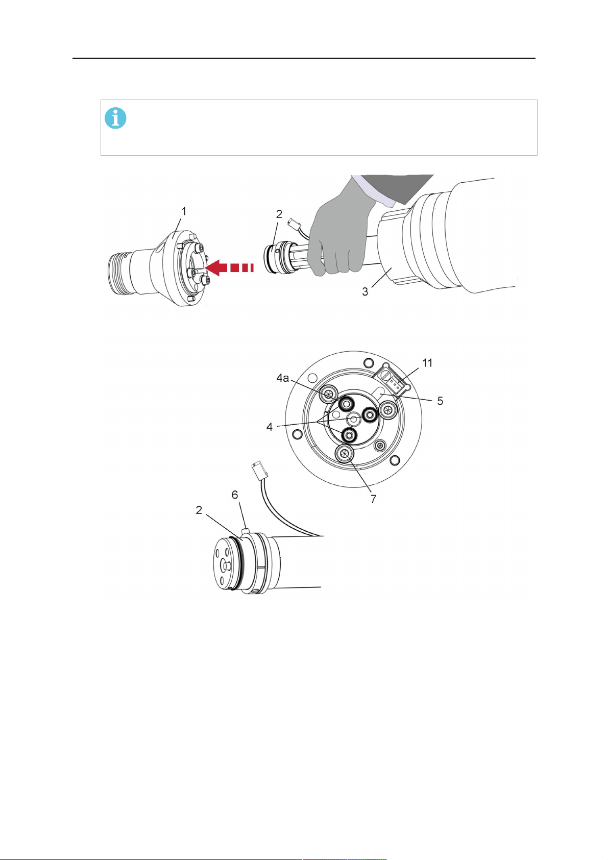
1. Remove the three screws (2) from the front cover (3) of the torch mount and carefully
pull the cover off the RTKSC-2 main body (5). Take care not to damage the micro
switches installed inside the assembly.
1 - Hexagon wrench 4 mm 4 - Rubber boot
2 - 3× M5×12 screws 5 - RT KSC-2 main body
3 - RT KSC-2 front cover
1. Pull off the rubber boot (4) from the RTKSC-2 main body (5) to the front.
2. Now position the RTKSC-2 main body (5) on the adapter flange (7) so that the index
pin is correctly seated. Attach with the screws (6) enclosed.
3. Reinstall the rubber boot (4) on the RTKSC-2 main body (5) and make sure it is
correctly located in the grooves on the front and back flange.
4. Istall the adapter flange (7) on the robot.
Fastening torque max. 2.2 Nm (19.5 in.lb).
1 - Hexagon wrench 4 mm 3 - 3× M5×12 hexagon socket screws
2 - Rubber boot 4 - Adapter flange
5.3.2 Mounting the cable assembly
ЗАБЕЛЕЖКА!
In order to adjust the wire feeder position to the cable assembly length, it must be
mounted on an adjustable support with a possible movement of ±2-3cm (±1in.) to
the back and to the front. The length of the cable assembly must be determined
from the centred mounting position of the wire feeder.
1. Move the robot arm into a completely straight position, see illustration below. Make
sure that (1) axis 6 (rotation around the torch axis) is in 0° position.
2. Move the feeder (3) completely to the back in order to create space for inserting the
cable assembly. If it is not possible to move the feeder sufficiently, it should be
removed from the robot.
0463 373 101
- 34 -
© ESAB AB 2018

5 INSTALLATION
3. Insert the cable assembly with the coupling (2) first into the robot arm and feed it
through the robot wrist.
4. The feeder should only be installed again after the correct mounting position with
respect to the cable length has been determined. (See section "Installing the cable
assembly").
ВНИМАНИЕ!
Axis 6 must be in 0° position.
5.3.2.1 RTKSC-2 feeder cabinet connections
When installed for the first time, the position of the wire feeder cabinet must be adjusted to
the length of the cable assembly. First, the robot arm must be fully extended (straight).
ВНИМАНИЕ!
As long as the correct position of the feeder corresponding to the length of the cable
assembly has not been determined, be careful when moving the robot arm and
avoid overstretching the cable. It is helpful to loosen the positioning screws of the
feeder before moving the robot arm to allow the feeder to follow the cable assembly.
0463 373 101
- 35 -
© ESAB AB 2018

5 INSTALLATION
1. Loosen the sliding mechanism of the wire feeder and connect the cable assembly.
2. Now adjust the position of the wire feeder to suit the length of the Infiniturn or Helix
cable, as indicated with "A" in the illustration below.
ВНИМАНИЕ!
When adjusting the position of the feeder cabinet, make sure that the cable
assembly is not under stress when the robot arm is in stretched-out position.
It is normal for the cable assembly to sag slightly, it should never be taut.
3. Before securing the wire feeder in its permanent position, ensure that the Euro
connectors are tightly connected. Then turn the torch mount down and up again
(rotating on the axis 5), in order not to tighten the cable assembly too much against
the feeder (see illustration above). Once this is done, tighten the feeder in that
position.
4. For water cooled systems, connect the water lines to the cooling circuit. See section
"Cable assemblies for hollow wrist systems" in the TECHNICAL DATA chapter for
indications.
The hose with the blue rubber cap is for cooling water to the torch, the hose with the
red rubber cap returns the heated water. Make sure the hoses will not kink or get
otherwise blocked.
ЗАБЕЛЕЖКА!
A Helix cable assembly used for a gas cooled system must not be connected
to a cooling circuit. As the water connections are not needed, they may be cut
off.
5. Connect the blow-out hose (black rubber cap) to the corresponding outlet of the wire
feeder.
ЗАБЕЛЕЖКА!
If the blow-out function is not used, the blow-out hose must be sealed with the
rubber cap enclosed. With Infiniturn systems, the blow-out air must be
supplied to the corresponding connection hose, if it is not permitted to connect
blow-out air to the shield gas connection!
6. Install the necessary plug on the control cable and connect it to the safety off circuit
interface of the wire feeder (see section "Electrical connections").
0463 373 101
- 36 -
© ESAB AB 2018

5 INSTALLATION
5.3.3 RTKSC-2 cable assembly
The cable assembly must be aligned to the intended use in length and design. The type of
cooling for the torch and the cable assembly must be the same (either gas or water cooled
respectively). In order to prevent damage to the torch system and other components, it is
imperative to observe the following instructions.
ВНИМАНИЕ!
• Coordinate the length and design of the cable assembly to suit the range of
action of the robot.
• Do not bend, compress or overstretch the cable assembly.
• Fix the cable assembly such that is can be moved freely and cannot become
entangled.
• Any additional holding devices possibly installed, for example a balancer,
must not crush or bend the cable assembly.
• Extreme turning movements must be avoided in which the cable assembly
may become twisted.
• Chafing on the robot or other objects must be excluded.
5.3.3.1 RTKSC-2 cable assembly installation
ЗАБЕЛЕЖКА!
For some robots, it may be possible to deviate from this order, and first connect the
cable assembly to the RTKSC-2, then thread the cable from the front through the
robot arm. If in doubt, follow the suggested order.
1. Loosen the three screws (7) with the associated washers and remove them from the
RTKSC-2 cover (1). See illustration below.
2. Install the supplied O-rings (4) into the grooves in the cover (1).
3. Pull the cable assembly approximately 15 cm (6 in.) from the main body (3).
0463 373 101
- 37 -
© ESAB AB 2018

5 INSTALLATION
4. Insert the coupling (2) into the socket of the cover (1) as shown. Align the index pin (6)
with the index hole (5) in the main body and insert completely.
ЗАБЕЛЕЖКА!
Make sure that the position of the O-rings are not shifted by the index pin
during the assembly.
1 - RTKSC-2 cover 5 - Index hole
2 - Coupling 6 - Index pin
3 - RTKSC-2 main body 7 - 3× M5×35 screws
4 - 3× O-ring for water cooled systems 11 - Control cable connector
5. Insert the three screws (7) with the associated washers (8) and tighten gently with the
enclosed hexagonal wrench, see below illustration.
Fastening torque approximately 2 Nm (18 in.lb).
0463 373 101
- 38 -
© ESAB AB 2018

5 INSTALLATION
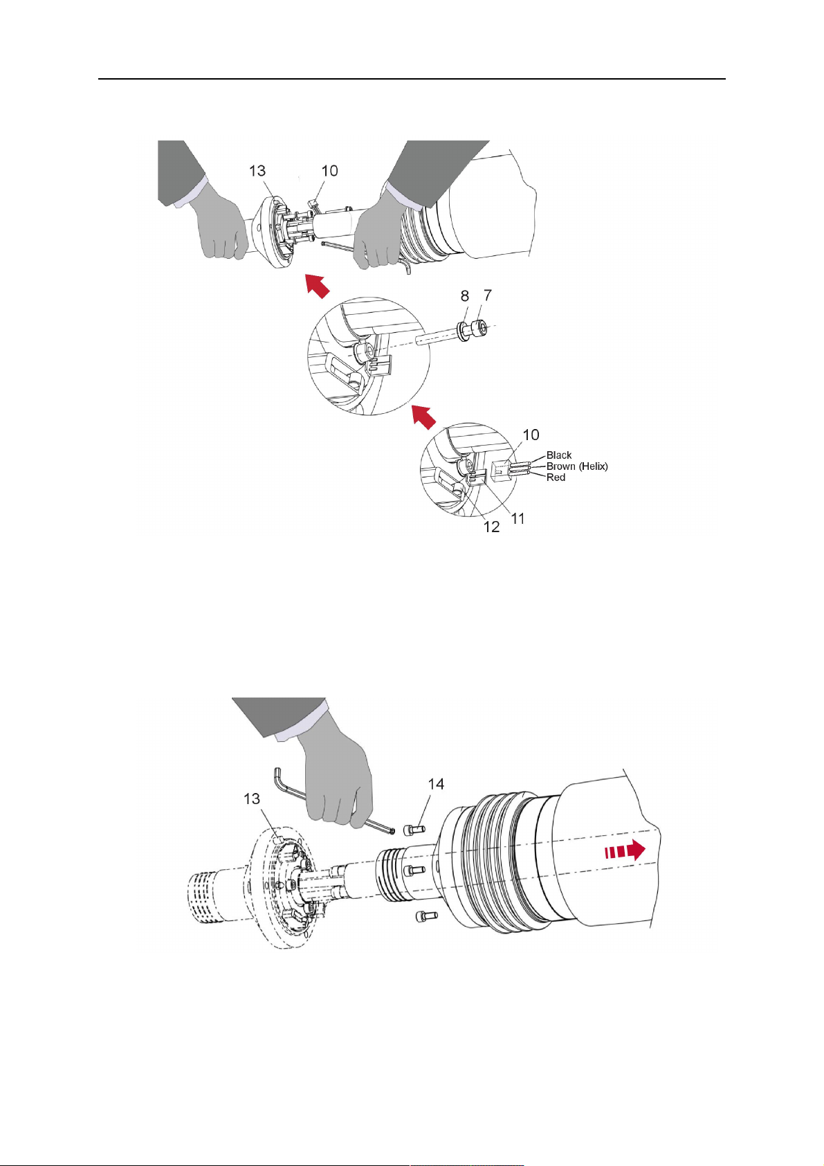
6. If present, insert the control cable plug (10) into the connector (11) and make sure it is
firmly seated.
7 - 3× M5×35 screw 11 - Control cable connector
8 - Washer 12 - 2× Micro switch
10 - Control cable plug 13 - Index pin
7. Gently push back the cable assembly into the robot arm and carefully seat the
RTKSC-2 cover (1) in place. Observe the index pin (13) to be in the correct position.
Make sure the two micro switches (12) are not damaged if present.
8. Insert the three M5 screws (14) and tighten without excessive force.
13. Index pin
14. 3× M5×12 screws
0463 373 101
- 39 -
© ESAB AB 2018

5 INSTALLATION
5.3.3.2 RTKSC-2 electrical connections
ЗАБЕЛЕЖКА!
After connecting the control cable, secure the cable in order to protect it from getting
caught while the robot is moving.
Usually, the control cable will be directly connected to the wire feeder. See the
manufacturer's documentation for details. The link to the robot control is then
implemented via the power source controller.
RTKSC-2 safety-off mechanism connection
The switch for the safety-off functionality RTKSC-2 is connected through the control cable,
see (3) in the illustration below. This connects to the RTKSC-2 unit via the control cable plug
(1).
The safety-off signal requires a 2-wire connection (black/black) to the safety-off circuit in the
robot control (5).
If a collision is detected, the control circuit (normally closed) will be interrupted (4).
Rating of the control circuit: max. 48 V / 1 A.
1 - Control cable plug 3 - Burndy connector VVV
2 - EURO central connector
Изводи на конектор Burndy
A. Контактно възприятие,
газова дюза
C. Датчик за сблъсък
D. Датчик за сблъсък
E. Бавно движение
F. 0V
G. + напрежение на
двигателя
Н. – напрежение на
двигателя
RTKSC-2 nozzle sense function connection
If the robot control provides a control circuit for nozzle sense functionality.
The connection is accomplished with a 2-wire connection (black/black) to the nozzle sense
circuit in the robot control (5), see illustration below.
0463 373 101
- 40 -
© ESAB AB 2018

5 INSTALLATION
Usually, the control cable will be directly connected to the wire feeder. See the
manufacturer's documentation for details. The link to the robot control is then implemented
via the power source robot interface.
Rating of the control circuit: max. 50 V / 5 A.
ОПАСНОСТ!
If the nozzle sense function is not being used, the open end of the control cable on
the power source connection side must be properly isolated in order to avoid short
circuits. During certain problems on the torch head, the full welding potential may be
present on this cable.
ВНИМАНИЕ!
After detection of contact (gas nozzle on work piece), quickly reduce or cut off the
maximum current in the nozzle sense circuit in order to avoid overloading of the
system.
Allowed load max. 1 minute at the rated nominal current.
1 - Control cable plug 3 - Control cable
2 - EURO central connector
5.3.4 RTKSC-2 torch installation
Continue according to section "Torch installation".
0463 373 101
- 41 -
© ESAB AB 2018

5 INSTALLATION
5.4 RTFLC-2 installation
5.4.1 RTFLC-2 mount
1. Remove the three M5 screws (2) from the front cover (3) of the RT FLC-2 torch mount
and carefully pull the cover off the main body (4).
1 - Hexagon wrench 4 mm 3 - RT FLC-2 front cover
2 - 3× M5×12 screws 4 - RT FLC-2 main body
2. Now position the RT FLC-2 main body (4) on the adapter flange (6) so that the index
pin is correctly seated. Attach with the screws (5) enclosed
Fastening torque max. 2.2 Nm (19.5 in.lb).
1 - Hexagon wrench 4 mm 5 - 3× M5×12 hexagon socket screws
4 - RT FLC-2 main body 6 - Adapter flange
5.4.2 RTFLC-2 wire feeder connection
5.4.2.1 Feeding through the robot arm
ЗАБЕЛЕЖКА!
In order to adjust the wire feeder position to the cable assembly length, it must be
mounted on an adjustable support with a possible movement of ± 2-3 cm (± 1 in.) to
the back and to the front. The length of the cable assembly must be determined
from the centred mounting position of the wire feeder.
0463 373 101
- 42 -
© ESAB AB 2018

5 INSTALLATION
1. Move the robot arm into a completely straight position, see illustration below. Make
sure that (1) axis 6 (rotation around the torch axis) is in 0° position.
2. Move the feeder (3) completely to the back in order to create space for inserting the
cable assembly. If it is not possible to move the feeder sufficiently, it should be
removed from the robot.
3. Insert the cable assembly with the coupling (2) first into the robot arm and feed it
through the robot wrist.
4. The feeder should only be installed again after the correct mounting position with
respect to the cable length has been determined. (See section "Installing the cable
assembly").
ВНИМАНИЕ!
Important! Axis 6 must be in 0° position.
5.4.2.2 RTFLC-2 feeder cabinet connections
When installed for the first time, the position of the wire feeder cabinet must be adjusted to
the length of the cable assembly. First, the robot arm must be fully extended (straight).
ВНИМАНИЕ!
As long as the correct position of the feeder corresponding to the length of the cable
assembly has not been determined, be careful when moving the robot arm and
avoid overstretching the cable. It is helpful to loosen the positioning screws of the
feeder before moving the robot arm to allow the feeder to follow the cable assembly.
0463 373 101
- 43 -
© ESAB AB 2018

5 INSTALLATION
1. Loosen the sliding mechanism of the wire feeder and connect the cable assembly.
Refer to the instruction of the feeder manufacturer.
2. Now adjust the position of the wire feeder to suit the length of the Infiniturn or Helix
cable, as indicated with "A" in the illustration below.
ВНИМАНИЕ!
When adjusting the position of the feeder cabinet, make sure that the cable
assembly is not under stress when the robot arm is in stretched-out position.
It is normal for the cable assembly to sag slightly, it should never be taut.
3. Before securing the wire feeder in its permanent position, ensure that the Euro
connections are tightly connected. Then turn the torch mount down and up again
(rotating on the axis 5), in order not to tighten the cable assembly too much against
the feeder (see illustration above). Once this is done, tighten the feeder in that
position.
4. For water cooled systems, connect the water lines to the cooling circuit. See section
"Cable assemblies for hollow wrist systems" in the TECHNICAL DATA chapter for
indications.
The hose with the blue rubber cap is for cooling water to the torch, the hose with the
red rubber cap returns the heated water. Make sure the hoses will not kink or get
otherwise blocked.
ЗАБЕЛЕЖКА!
A Helix cable assembly used for a gas cooled system must not be connected
to a cooling circuit. As the water connections are not needed, they may be cut
off.
5. Connect the blow-out hose (black rubber cap) to the corresponding outlet of the wire
feeder.
ЗАБЕЛЕЖКА!
If the blow-out function is not used, the blow-out hose must be sealed with the
rubber cap enclosed. With Infiniturn systems, the blow-out air must be
supplied to the corresponding connection hose, if it is not permitted to connect
blow-out air to the shield gas connection!
0463 373 101
- 44 -
© ESAB AB 2018

5 INSTALLATION
6. Install the necessary plug on the control cable and connect it to the safety off circuit
interface of the wire feeder (see section "Electrical connections").
5.4.3 RTFLC-2 cable assembly
The cable assembly must be aligned to the intended use in length and design. The type of
cooling for the torch and the cable assembly must be the same (either gas or water cooled
respectively). In order to prevent damage to the torch system and other components, it is
imperative to observe the following instructions.
ВНИМАНИЕ!
• Coordinate the length and design of the cable assembly to suit the range of
action of the robot.
• Do not bend, compress or overstretch the cable assembly.
• Fix the cable assembly such that is can be moved freely and cannot become
entangled.
• Any additional holding devices possibly installed, for example a balancer,
must not crush or bend the cable assembly.
• Extreme turning movements must be avoided in which the cable assembly
may become twisted.
• Chafing on the robot or other objects must be excluded.
5.4.3.1 RTFLC-2 cable assembly installation
In a hollow wrist system the recommended order of installation is to feed the cable assembly
through the robot arm before connecting the cables to the torch mount.
When the cable assembly is correctly installed in the hollow wrist, continue the installation
according to the procedure described below.
ЗАБЕЛЕЖКА!
For some robots, it may be possible to deviate from this order, and first connect the
cable assembly to the RTKSC-2 and RTFLC-2, then thread the cable from the front
through the robot arm. If in doubt, follow the suggested order.
1. Loosen the three screws (7) with the associated washers and remove them from the
RTFLC-2 cover (1). See illustration below.
2. Install the supplied O-rings (4) into the grooves in the cover (1). For gas cooled
systems, only one O-ring (4a) is needed, for water cooled systems all three O-rings
are needed.
3. Pull the cable assembly approximately 15 cm (6 in.) from the main body (3).
0463 373 101
- 45 -
© ESAB AB 2018
5 INSTALLATION
4. Insert the coupling (2) into the socket of the cover (1) as shown. Align the index pin (6)
with the index hole (5) in the main body and insert completely.
ЗАБЕЛЕЖКА!
Take great care that the position of the O-rings is not shifted by the index pin
during the assembly.
1 - RT FLC-2 cover 5 - Index hole
2 - Coupling 6 - Index pin
3 - RT FLC-2 main body 7 - 3× M5×35 screws
4 - 3× O-ring for water cooled systems 11 - Control cable connector
5. Insert the three screws (7) with the associated washers (8) and tighten gently with the
enclosed hexagonal wrench, see below illustration.
Fastening torque approximately 2 Nm (18 in.lb).
0463 373 101
- 46 -
© ESAB AB 2018
5 INSTALLATION
6. If present insert the control cable plug (10) into the connector (11) and make sure it is
firmly seated.
7 - 3× M5×35 screw 11 - Control cable connector
8 - Washer 12 - 2× Micro switch
10 - Control cable plug 13 - Index pin
7. Gently push back the cable assembly into the robot arm and carefully seat the
RTFLC-2 cover (1) in place. Observe the index pin (13) to be in the correct position.
Make sure the two micro switches (12) are not damaged if present.
8. Insert the three M5 screws (14) and tighten without excessive force.
13 - Index pin 14 - 3x M5x12 screws
0463 373 101
- 47 -
© ESAB AB 2018

5 INSTALLATION
5.4.4 RTFLC-2 electrical connections
ЗАБЕЛЕЖКА!
After connecting the control cable, secure the cable in order to protect it from getting
caught while the robot is moving.
Usually, the control cable will be directly connected to the wire feeder. See the
documentation of the manufacturer for details. The link to the robot control is then
implemented via the power source controller.
5.4.4.1 RTFLC-2 hollow wrist system with Infiniturn cable assembly
Connecting the nozzle sense function
If the robot control provides a control circuit for nozzle sense functionality.
The connection is accomplished with a 2-wire connection (black/black) to the nozzle sense
circuit in the robot control (5), see illustration below.
Usually, the control cable will be directly connected to the wire feeder. See the
manufacturer's documentation for details. The link to the robot control is then implemented
via the power source robot interface.
Rating of the control circuit: max. 50 V / 5 A.
ОПАСНОСТ!
If the nozzle sense function is not being used, the open end of the control cable on
the power source connection side must be properly isolated in order to avoid short
circuits. During certain problems on the torch head, the full welding potential may be
present on this cable.
ВНИМАНИЕ!
After detection of contact (gas nozzle on work piece), quickly reduce or cut off the
maximum current in the nozzle sense circuit in order to avoid overloading of the
system.
Allowed load max. 1 minute at the rated nominal current.
1 - Control cable plug 3 - Control cable
2 - EURO central connector
0463 373 101
- 48 -
© ESAB AB 2018

5 INSTALLATION
5.4.4.2 RTFLC-2 hollow wrist system with Helix cable assembly
Connecting the nozzle sense function
If the robot control provides a control circuit for nozzle sense functionality.
The connection is accomplished with a 1-wire connection (green) to the nozzle sense circuit
in the robot control (5), see illustration below.
Usually, the control cable will be directly connected to the wire feeder. See the
manufacturer's documentation for details. The link to the robot control is then implemented
via the power source robot interface.
Rating of the control circuit: max. 50 V / 5 A.
ОПАСНОСТ!
If the nozzle sense function is not being used, the open end of the control cable on
the power source connection side must be properly isolated in order to avoid short
circuits. During certain problems on the torch head, the full welding potential may be
present on this cable.
ВНИМАНИЕ!
After detection of contact (gas nozzle on work piece), quickly reduce or cut off the
maximum current in the nozzle sense circuit in order to avoid overloading of the
system.
Allowed load max. 1 minute at the rated nominal current.
1 - Control cable plug 3 - EURO central connector
2 - Control cable 4 - Burndy connector
5.5 Torch installation
Be sure to use the correct version of the torch mount and cable assembly (water or gas
cooled).
5.5.1 Torch neck equipment
The torch neck, see (1) in the illustration below, must always be equipped to suit the wire
diameter and material.
0463 373 101
- 49 -
© ESAB AB 2018

5 INSTALLATION
1. Select the correct wire guide, contact tip (4), tip holder (2), gas nozzle (5), and gas
diffuser/spatter protection (3). You will find an exact overview and possible alternative
equipment elements for various torch models in the spare parts list. Only use original
ESAB parts; only then is the fitting accuracy ensured.
2. Firmly tighten the tip holder and the contact tip using a suitable tool for example the
enclosed monkey wrench.
3. When using a split wire guide, remove the installed guide nipple including the o-ring
from the torch flange upon delivery if necessary (see section "Installing the neck
liner").
ВНИМАНИЕ!
The torch must be completely equipped before welding, especially the gas
diffuser and/or spatter protection and all necessary insulators have to be
installed according to the spare parts list. Welding without these items may
cause immediate destruction of the torch.
1 - Torch neck 4 - Contact tip
2 - Tip holder 5 - Contact tip
3 - Gas diffuser
5.5.2 Aristo RT torch neck installation
ЗАБЕЛЕЖКА!
Check the O-rings on the flange of the torch neck before mounting. Replace the
O-rings if damaged or lost. Missing or faulty O-rings will lead to leaks of shielding
gas and coolant.
1. For hollow wrist systems, insert the torch into the torch mount in the correct
orientation, so that the locator pin fits into the slot of the RTKSC-2 or RTFLC-2
interface, see (A) in the illustration below. For standard systems, attach the torch to
the RT flange of the cable assembly, (B) in the illustration below.
Installation is only possible in the correct orientation.
2. Tighten the locking nut of the torch neck.
ЗАБЕЛЕЖКА!
Only tighten by hand, never use tools or excessive force.
0463 373 101
- 50 -
© ESAB AB 2018

5 INSTALLATION
3. The correct seating of the torch can be checked by means of the window (1). If the
torch has been correctly mounted, no gap should be seen through the window (1).
5.6 Installing the wire guide for standard and hollow Wrist arm
Installing the wire guide
Choose the wire guide or liner depending on the filler wire material and diameter to be used,
see the spare parts list. Accurate performance of the system can only be guaranteed when
using original ESAB wire guides.
The recommended wire guide is the split wire guide, which consists of the neck liner and a
separate guide in the cable assembly. The front part of the wire guide, which is most
stressed, can be exchanged easily and independently of the cable assembly wire guide.
For correct installation, the following steps must be followed (example for Euro central
connector).
5.6.1 Installing the neck liner
The neck liner must be selected to fit the material and diameter of the welding wire, see the
spare parts list.
0463 373 101
- 51 -
© ESAB AB 2018

5 INSTALLATION
1. If present, remove the central guide nipple (1), from the torch neck using a hexagon
wrench (size 6 mm) or a large flat-blade screwdriver.
ЗАБЕЛЕЖКА!
The guide nipple (1) can only be used with one-piece liners and must not be
used with the standard RT or hollow wrist system.
2. When replacing the neck liner:
Unfasten the sleeve nut and remove the torch neck.
Unfasten the liner nipple using a hexagon wrench (size 6 mm) and remove nipple and
liner from the torch neck.
3. Remove the gas nozzle and the contact tip.
4. Insert the new neck liner (2) into the torch. Carefully tighten the guide nipple using a
suitable tool, e.g. a hex-wrench (size 6 mm) or a large flat-blade screwdriver.
5. Cut the neck liner flush with the tip holder and remove the neck liner from the torch.
6. Install the contact tip.
7. Insert the neck liner again. It will be stopped by the contact tip. Measure the excess
liner sticking out of the neck.
8. Remove the liner again and shorten the front end by the measured length. Carefully
deburr the edge and make sure that the inner hole is not blocked.
9. Reinstall the neck liner and tighten the guide nipple in the neck.
5.6.2 Installing a split wire guide in the cable assembly
The correct liner must be inserted to suit the filler material and the wire diameter, see the
spare parts list.
The wire guide is inserted through the cable assembly from the rear, reaching the guide
nipple that is installed in the flange where the torch neck will be attached. The following
worksteps must be followed in order to correctly determine the wire guide length. (Example
for Euro central connector).
0463 373 101
- 52 -
© ESAB AB 2018

5 INSTALLATION
1. For standard RT system: Install the guide nipple (1) in the center hole of the neck
support flange, see illustration A below.
For hollow wrist system: Install the guide nipple (1) into the torch interface of the
RTKSC-2 / RTFLC-2 cover, see illustration B below.
2. Remove the sleeve nut (2) from the central connector, and remove the old wire guide.
3. Insert the wire guide through the central connection and push forwards as far as it will
go into the guide nipple (1), applying light pressure.
ВНИМАНИЕ!
Ensure that the wire guide has advanced right up to the stop at the front,
rotating and pushing forward gently.
4. Measure the excess length that needs to be cut from the wire guide.
5. Remove the wire guide again and shorten the front end by the measured length.
Steel liner: grind down the burred edges if needed.
Plastic liner: make a clean cut and chamfer the edges (e.g. with a pencil sharpener)
ЗАБЕЛЕЖКА!
Make sure the inner opening of the liner is not obstructed by the cut wire end.
0463 373 101
- 53 -
© ESAB AB 2018

5 INSTALLATION
6. Reinstall the wire guide and attach the sleeve nut (2).
ЗАБЕЛЕЖКА!
For hollow wrist systems where Infiniturn and Helix cable assemblies are
used, wire guides should be installed without tension so that the ends of the
liners may rotate freely.
Important note when using a plastic liner:
The wire channel between the drive rolls of the feeder and the central
connector of the torch must be fitted with a plastic liner. Depending on the
design of the feeder, a piece of plastic liner inserted into a brass guide tube
can be used.
During wire run-in, make sure that the wire is fed correctly into the plastic liner
of the torch. If necessary, remove the cable assembly from the feeder and
insert the wire, then reattach.
5.6.3 Installing a continuous wire guide in the cable assembly
Installing a steel liner
The wire guide is inserted through the cable assembly from the rear and reaches to the
contact tip. The following worksteps must be followed for the correct calculation of the length
(example for Euro central connector):
1. Install the torch (see section "Torch neck equipment").
2. Remove the gas nozzle and contact tip from the torch.
3. Remove the sleeve nut (D) from the Euro connector.
4. Push in the liner through the central connector and fix with the sleeve nut.
5. Cut off the liner flush with the nozzle holder. To determine the thread projection of the
contact tip, pull the liner backwards and screw in the contact tip.
6. Push the liner forwards as far as it will go to the contact tip applying light pressure on
the liner and measure the length to be shortened at the rear.
7. Now remove the liner again and cut the excess length measured off it’s front end. If
needed, grind down the burred edges. Make sure the inner opening of the liner is not
obstructed by the cut wire end.
8. The insulation of the liner must be removed after cutting off in the front area, such that
the insulation protrudes out of the RM2 flange by approx. 5 cm. For this, briefly
remove the torch neck.
9. Push the liner back in again and fix with the sleeve nut (D), see above. Re-install the
gas nozzle.
0463 373 101
- 54 -
© ESAB AB 2018

5 INSTALLATION
Installing a plastic liner
1. Mount the torch neck (see section "Torch neck equipment") and equip it with a gas
nozzle and contact tip.
2. Remove the sleeve nut (D) from the Euro connector.
3. Cleanly cut off the liner, slightly break the outer edges, point slightly (e.g. with a pencil
sharpener).
4. Insert the liner through the central connector into the cable assembly with fitted torch.
If it gets stuck, rotate the liner to free it and facilitate installation.
ЗАБЕЛЕЖКА!
Make sure the liner is completely inserted by rotating it and slightly pushing it
forward, until you can feel it has reached its stop.
5. Mount the nipple (B) and the O-Ring (C), move it to the right position and fix it with the
sleeve nut (D) of the Euro central connector.
6. Measure the required overlap needed inside the wire feeder cabinet and cut the liner
accordingly.
5.7 Adjust the narrow gap contact tip
The adjusting tool RT42-NG is designed for the narrow gap torch necks RT42W-NG,
RT42G-NG and RT 82W-0°NG, torches with curved narrow gap contact tip. It facilitates the
precisely repeatable and fast changing of the curved contact tip.
ЗАБЕЛЕЖКА!
The adjusting tool must be securely fastened to a stable base, in order to prevent
the position of the device in relation to the robot cannot change unintentionally. If the
exact orientation of the device is lost, the alignment of the contact tip used for the
elaboration of the welding programs can no longer be reproduced with precision.
Select a position within the operating range of the robot for orientation (alignment) of the
contact tip to the torch. Fasten the adjusting tool firmly to a base using the fastening grooves
provided for this purpose. Fastening material is not included with the adjusting tool. Select
fastening material (screws) to suit the existing conditions.
Save all motion sequences and stop positions required to change or align the wearing parts
to a separate robot program.
Before programming the welding tasks: plan at which orientation the contact tip is to stand in
relation to the torch. The torch must then be positioned in the desired rotational position and
the contact tip aligned using the adjusting device. Only then may the welding task be
programmed. If different orientations of the contact tip are required for various welding tasks,
the contact tip has to be aligned to the new position when the welding task is changed.
ПРЕДУПРЕЖДЕНИЕ!
The gas nozzle and the torch head become very hot during welding. Always allow
the torch to cool down before replacing wearing parts or adjusting the contact tip.
0463 373 101
- 55 -
© ESAB AB 2018

5 INSTALLATION
Adjust the contact tip
Move the robot torch to a position parallel to
the opening of the adjusting tool (2). Maintain
a sufficient distance to the work table to be
able to comfortably remove the gas nozzle.
Define this position in your robot program as
the wearing parts change position (stop
position 1).
Remove the gas nozzle by pulling it
downwards. Remove the welding wire in the
contact tip if necessary.
Loosen the counter nut (4) of the contact tip
while counter-holding the nozzle holder at the
wrench flat (3).
Unscrew the contact tip including the counter
nut from the nozzle holder and replace the
nozzle holder if necessary.
Completely screw the counter nut (4) onto the
new contact tip. Screw the contact tip
including the counter nut into the nozzle
holder.
Align the contact tip until it is parallel to the
opening of the adjusting tool. If necessary,
slightly unscrew the contact tip so that it can
be easily turned in both directions.
0463 373 101
- 56 -
© ESAB AB 2018

5 INSTALLATION
ЗАБЕЛЕЖКА!
The contact tip must be able to be
easily moved by hand in both
directions in order to enable the
threading of the adjusting tool.
Place the robot torch or contact tip directly in
front of the opening of the adjusting tool (2)
(stop position 2).
Insert it slowly from the front until it is
completely inserted into the device (stop
position 3).
The contact tip was aligned exactly in the
device during insertion. Now cautiously
tighten the counter nut (4) in this position,
while counter holding the nozzle holder at the
wrench flat.
Slowly move the robot torch out of the
adjusting gauge, return to stop position 1 and
push on the gas nozzle as far as it will go.
Allow the welding wire to run into the contact
tip and bring the robot arm into welding
position.
0463 373 101
- 57 -
© ESAB AB 2018

6 OPERATION
6 OPERATION
ВНИМАНИЕ!
Before starting the system, check the whole installation according to the
manufacturer's instructions and applicable safety regulations.
Check the following to make sure that the system has been installed correctly:
1. Are all parts securely attached (torch, torch mount, flanges, safety-off device, cable
assembly, and wire feeder cabinet)?
2. Are all media hoses connected correctly and protected from damage?
3. Is the EURO central connector or direct connector fastened tightly?
4. Is the cable assembly length correct and suitable for the installation and can the cable
rotate freely? The cable must not be bent sharply. Any risk of the cable getting caught
on another object must be eliminated.
5. Is the control cable of the safety-off circuit connected and functioning? Move torch by
hand to test (RTKSC-2 and RTKS-2 only).
6. Is the torch firmly attached and is it completely equipped?
7. Is the wire guide installed according to the manual?
8. Are all lines and tubes arranged so that they cannot be damaged or bent?
The wire run-in can now be started, either via the wire run-in pushbutton or via the wire run-in
at the feeder.
6.1 Important information for programming (hollow wrist system only)
Fast rotation of axis 6 of the robot will significantly stress the cable assembly. In certain
cases, this can lead to damage or destruction of the cable. In order to maximize the lifetime
of the cable, we strongly suggest respecting the following limitations when programming the
robot.
Position of axis 5 Max. rotational speed of axis 6
0 – 60° 100 % (no limitations)
60° – 80° 300°/sec (approximately 50 % of max. robot speed)
> 80° 120°/sec (approximately 20 % of max. robot speed)
ЗАБЕЛЕЖКА!
The above values are only indications. For information on the exact rotational speed
limits, refer to the individual robot manual or contact the robot supplier.
To reposition the torch quickly, the robot arm may have to be slightly extended first to achieve
a bending angle of max. 60° of axis 5. In this position, the maximum available rotation speed
of axis 6 can be used.
When using the ESAB Helix cable assembly, the max. rotation of ±270° from the neutral
position must not be exceeded.
0463 373 101
- 58 -
© ESAB AB 2018

6 OPERATION
ВНИМАНИЕ!
While axis 5 is bent more than 60°, the rotational speed of the torch around axis 6
must be limited, see table above.
Otherwise, the cable assembly may be damaged.
0463 373 101
- 59 -
© ESAB AB 2018

7 СЕРВИЗ И ТЕХНИЧЕСКО ОБСЛУЖВАНЕ
7 СЕРВИЗ И ТЕХНИЧЕСКО ОБСЛУЖВАНЕ
ПРЕДУПРЕЖДЕНИЕ!
Преди извършване на техническо обслужване на системата основното
захранване на инсталацията трябва да бъде изключено. Обърнете внимание
на правилата за безопасност в началото на настоящото ръководство.
Повредени горелки или кабелни комплекти не трябва да се използват!
Известните дефекти трябва да бъдат отстранени от квалифициран персонал
преди следващата употреба на оборудването.
ПРЕДУПРЕЖДЕНИЕ!
Опасност от изгаряне! Газовата дюза и главата на горелката се нагряват много
по време на заваряване. Преди техническо обслужване оставете горелката да
се охлади.
ПРЕДУПРЕЖДЕНИЕ!
За да предотвратите телесни повреди или повреда на Вашата инсталация,
спазвайте следните инструкции:
1. Ремонтът на държача на горелката RT KSC-2 или RT FLC-2, защитния
механизъм RT KS-2, кабелния комплект или съединението за среда
Infiniturn трябва да се извършва само от сервиз на ESAB.
2. Съединението за среда Infiniturn никога не трябва да се отваря. Той
съдържа части, които не могат да се обслужват от потребителя, и при
разглобяване ще бъде разрушено.
3. Никога не разглобявайте RTKSC-2 или RTKS-2. Това е пружинен
механизъм. Неправилната манипулация може да доведе до сериозно
нараняване.
7.1 Задължителни проверки и дейности
Преди всяка употреба:
• Проверете горелката, контактния връх, газовата дюза, водещата втулка на
накрайника, кабелите и цялостното оборудване за общи повреди.
ЗАБЕЛЕЖКА!
За да се сведе до минимум времето за престой, се препоръчва да се редуват
два накрайника на горелката, като винаги имате под ръка новооборудван готов
за употреба накрайник за горелката.
На всеки 8 часа употреба (в зависимост от приложението):
• Сменете контактния връх.
Ежедневно:
• Направете проверка на функцията на защитния механизъм на ръка.
• Направете визуална проверка за повреди, например за огъвания или пукнатини.
• Проверете правилното положение на телоподаващото устройство. Кабелният
комплект не трябва да бъде прекалено обтегнат или провиснал.
• Проверете връзките за среда и съединението Infiniturn за изтичане.
• Извършете почистване и техническо обслужване на горелката в съответствие с
ръководството за горелката.
0463 373 101
- 60 -
© ESAB AB 2018

7 СЕРВИЗ И ТЕХНИЧЕСКО ОБСЛУЖВАНЕ
На всеки 40 часа употреба (в зависимост от приложението):
• Сменете водещите втулки на тела.
• Сменете водещите втулки на накрайника.
Ежеседмично или според нуждите в зависимост от употребата:
• Извадете водача на тела и проверете за износване и замърсяване. Смяна при
необходимост.
Месечно или по-често при усилена употреба (т.е. повече от 8 часа на ден):
• Продухайте канала на водача на тела със сгъстен въздух (отстранете контактния
връх и водача на тела).
• Проверете дали всички винтове са стегнати.
• Проверете всички връзки и маркучи за повреди.
• Сменете след всички 250 kg заварен тел.
Повредата в електрическата изолация трябва да бъде отстранена от обучен персонал,
преди системата да бъде пусната в безопасна експлоатация.
0463 373 101
- 61 -
© ESAB AB 2018

8 ОТСТРАНЯВАНЕ НА НЕИЗПРАВНОСТИ
8 ОТСТРАНЯВАНЕ НА НЕИЗПРАВНОСТИ
Неизправност Възможна причина Действие
Не може да се
подава тел
Заваръчният тел не е изправен
преди подаването му в кабелния
комплект
Горелката и кабелният комплект
не са оборудвани в съответствие
с диаметъра и материала на тела
Водачът на тела не е поставен
правилно в кабелния комплект
Контактният връх е блокиран с
остатъци от тел
Водачът на тела е износен
Подаването на тел е
възпрепятствано от
замърсявания и остатъци в
горелката
Ако е необходимо, издърпайте
отново заваръчния тел, отрежете
и почистете края и изправете
първите 10 cm от тела. След това
отново го поставете в кабелния
комплект.
Проверете водача на тела
(кабелен комплект и накрайник на
горелката) и контактния връх.
Издърпайте малко водача на
тела от Euro конектора. Когато
поставяте водача на тела, трябва
да усетите, че последните
сантиметри се плъзгат във
водещия нипел в свързващия
елемент на горелката. В противен
случай водачът на тела може да
е твърде къс и да не е поставен
напълно.
Сменете контактния връх и/или
водача на тела, продухайте
накрайника на горелката, канала
на водача на тела със сгъстен
въздух.
Горелката се
нагрява
прекалено
много
Контактният връх или държачът
на върха не са достатъчно
Използвайте подходящ
инструмент за стягане на ръка.
стегнати
Охладителната система не
работи добре
Охладителната система не е
правилно свързана
Пистолетът е подложен на
прекомерно натоварване
Проверете дебита, нивото на
напълване и чистотата.
Проверете връзките (вход за
вода и връщаща линия).
Съблюдавайте техническите
данни, сменете с друг тип при
необходимост.
Дефектен комплект кабели Проверете кабелите, тръбите и
връзките.
0463 373 101
- 62 -
© ESAB AB 2018

8 ОТСТРАНЯВАНЕ НА НЕИЗПРАВНОСТИ
Неизправност Възможна причина Действие
Проблеми с
подаването на
телта
Подаването на
тел спира по
време на
заваряване
Износен контактен връх Сменете контактния връх.
Водачът е износен/замърсен Проверете водещата втулка;
продухайте. Смяна при
необходимост.
Използваните сменяеми части не
са подходящи за диаметъра или
Проверете списъка с резервни
части.
материала на заваръчния тел
Устройството за подаване на
заваръчен тел не е регулирано
правилно
Кабелният комплект е огънат или
е поставен с малък радиус
Проверете ролките за подаване
на заваръчен тел, контактния
натиск и спирачката на макарата.
Проверете кабелния комплект за
повреди. Може ли водещата
втулка да се постави лесно?
Поставете според инструкциите.
Вижте раздел „Монтиране на
кабелния комплект“.
Заваръчният тел е замърсен Използвайте почистващ филц.
Макарата с тел е празна Проверете количеството на
заваръчния тел на макарата в
подаващото устройство.
Блокиране на тела в кабелния
комплект
Проверете подаването на тел
(възможно е да е твърде бързо),
проверете контактния връх за
замърсяване/запушване,
почистете или сменете
контактния връх, ако е
необходимо.
Заваръчният
процес спира
Пори в
заваръчния
шев
Телът изгаря обратно в
Сменете контактния връх.
контактния връх или износен
контактен връх
Задействан е защитният
механизъм.
Потърсете точки на сблъсък и ги
предотвратете. Проверете
управляващата линия за
разхлабен контакт.
Завихряне на газ, предизвикано
от залепване на заваръчни
пръски
Прекалено малък или прекалено
голям газов поток в пистолета
Почистете главата на горелката,
използвайте дифузьор за
газ/защита от пръски.
Проверете дебита с
измервателен инструмент.
Проблем с газоподаването Проверете дебита и евентуално
изтичане.
Наличие на влага или
замърсявания по заваръчния тел
или обработвания детайл
Проверете заваръчния тел и
обработвания детайл,
използвайте по-малко или
различна течност срещу пръски.
0463 373 101
- 63 -
© ESAB AB 2018

8 ОТСТРАНЯВАНЕ НА НЕИЗПРАВНОСТИ
Неизправност Възможна причина Действие
Дъгата не е
стабилна
Износен контактен връх Сменете контактния връх.
Неправилни параметри на
заваряването
Недостатъчни електрически
връзки във веригата
Проверете настройките на
заваръчното оборудване.
Проверете дали всички
електрически връзки (вкл.
заземяващия кабел) между
горелката на източника на
захранване или работния детайл
са стабилни.
0463 373 101
- 64 -
© ESAB AB 2018

9 ПОРЪЧВАНЕ НА РЕЗЕРВНИ ЧАСТИ
9 ПОРЪЧВАНЕ НА РЕЗЕРВНИ ЧАСТИ
ВНИМАНИЕ!
Ремонтните и електрически поправки се извършват от оторизирани сервизни
специалисти на ESAB. Използвайте само оригинални резервни и износващи се
части ESAB.
Горелките ESAB RT – RTKS-2, RTFL-2, RT-KSC-2, RT-FLC-2, RT42, RT52, RT62,
RT72, RT82, RT42-NG, и RT82WNG са проектирани и тествани в съответствие с
международните и европейските стандарти IEC/EN 60974-7. Сервизното звено,
извършило обслужването или ремонтната дейност, трябва да провери дали продуктът
продължава да отговаря на посочените стандарти.
Може да поръчате резервни части и консумативи от най-близкия дилър на ESAB,
вижте esab.com. При заявка, моля, посочете типа на продукта, серийния номер,
обозначение и номер на резервната част в съответствие със списъка на резервните
части. Това улеснява и гарантира правилна доставка.
0463 373 101
- 65 -
© ESAB AB 2018

ESAB AB, Lindholmsallén 9, Box 8004, 402 77 Gothenburg, Sweden, Phone +46 (0) 31 50 90 00
http://manuals.esab.com
For contact information visit esab.com
 Loading...