


RT Robo Welding Torch System
RTKS-2, RTFL-2, KSC-2, FLC-2, RT42, RT52,
RT62, RT72, RT82, RT42-NG, RT82WNG
Návod na použitie
0463 373 101 SK 20181227


OBSAH
1
BEZPEČNOSŤ............................................................................................. 5
1.1 Význam symbolov .................................................................................. 5
1.2 Bezpečnostné opatrenia ........................................................................ 5
2
ZÁRUKA ...................................................................................................... 8
2.1 Podmienky určeného použitia............................................................... 8
3
ÚVOD ........................................................................................................... 9
3.1 Prehľad systémov zváracích horákov.................................................. 10
4
TECHNICKÉ ÚDAJE ................................................................................... 12
4.1 Hrdlo zváracieho horáka........................................................................ 12
4.2 Menovité napätie .................................................................................... 13
4.2.1 Obmedzenia chladiacich okruhov ........................................................ 14
4.3 Držiak horáka.......................................................................................... 14
4.3.1 Držiaky horáka pre štandardný systém RT .......................................... 14
4.3.1.1 Bezpečnostný vypínací mechanizmus RTKS-2................................ 15
4.3.1.2 Priechodová obruba RTFL-2 ............................................................ 15
4.3.2 Držiaky horáka pre systém sdutým zápästím...................................... 16
4.3.2.1 Držiak horáka RTKSC-2 G/W sbezpečnostným vypínacím
mechanizmom ...................................................................................
4.3.2.2 Pevný držiak horáka RTFLC-2 G/W................................................. 18
4.4 Adaptérové obruby................................................................................. 19
4.5 Káblové zväzky....................................................................................... 19
4.5.1 Káblové zväzky pre štandardný systém RT ......................................... 19
4.5.2 Káblové zväzky pre systémy spriechodným zápästím ........................ 20
5
INSTALLATION............................................................................................ 22
5.1 RTKS-2 standard arm installation........................................................ 22
5.1.1 RTKS-2 safety-off mechanism............................................................. 22
5.1.1.1 Torch installation with adjustable mount............................................ 23
5.1.2 Standard arm cable assembly for KS-2 and FL-2 ................................ 25
5.1.3 RTKS-2 wire feeder connection........................................................... 26
5.1.4 RTKS-2 electrical connections ............................................................ 27
5.1.4.1 RTKS-2 safety-off mechanism connection ....................................... 27
5.1.5 RTKS-2 Torch installation .................................................................... 28
5.2 RTFL-2 standard arm installation ........................................................ 29
17
5.2.1 RTFL-2 rigid mount.............................................................................. 29
5.2.2 RTFL-2 torch installation ..................................................................... 31
5.3 RTKSC-2 hollow wrist system installation.......................................... 31
5.3.1 RTKSC-2 mount with safety off mechanism........................................ 31
5.3.2 Mounting the cable assembly............................................................... 32
5.3.2.1 RTKSC-2 feeder cabinet connections .............................................. 33
5.3.3 RTKSC-2 cable assembly ................................................................... 35
5.3.3.1 RTKSC-2 cable assembly installation .............................................. 35
0463 373 101 © ESAB AB 2018

OBSAH
5.3.3.2 RTKSC-2 electrical connections....................................................... 38
5.3.4 RTKSC-2 torch installation .................................................................. 39
5.4 RTFLC-2 installation.............................................................................. 40
5.4.1 RTFLC-2 mount................................................................................... 40
5.4.2 RTFLC-2 wire feeder connection......................................................... 40
5.4.2.1 Feeding through the robot arm.......................................................... 40
5.4.2.2 RTFLC-2 feeder cabinet connections............................................... 41
5.4.3 RTFLC-2 cable assembly .................................................................... 43
5.4.3.1 RTFLC-2 cable assembly installation ............................................... 43
5.4.4 RTFLC-2 electrical connections .......................................................... 46
5.4.4.1 RTFLC-2 hollow wrist system with Infiniturn cable assembly........... 46
5.4.4.2 RTFLC-2 hollow wrist system with Helix cable assembly................. 47
5.5 Torch installation.................................................................................... 47
5.5.1 Torch neck equipment .......................................................................... 47
5.5.2 Aristo RT torch neck installation........................................................... 48
5.6 Installing the wire guide for standard and hollow Wrist arm ............. 49
5.6.1 Installing the neck liner......................................................................... 49
5.6.2 Installing a split wire guide in the cable assembly ................................ 50
5.6.3 Installing a continuous wire guide in the cable assembly ..................... 52
5.7 Adjust the narrow gap contact tip ........................................................ 53
6
OPERATION ................................................................................................ 56
6.1 Important information for programming (hollow wrist system only) 56
7
SERVIS A ÚDRŽBA..................................................................................... 58
7.1 Povinné kontroly aopatrenia ................................................................ 58
8
RIEŠENIE PROBLÉMOV ............................................................................ 60
9
OBJEDNÁVANIE NÁHRADNÝCH DIELOV ................................................ 62
Práva na zmenu technických údajov bez upozornenia vyhradené.
0463 373 101 © ESAB AB 2018

1 BEZPEČNOSŤ
1 BEZPEČNOSŤ
1.1 Význam symbolov
Ako sa používajú v tomto manuáli: Buďte opatrní! Dávajte pozor!
NEBEZPEČENSTVO!
Znamená bezprostredné ohrozenie, ktoré, pokiaľ mu nepredídete, môže
spôsobiť bezprostredný vážny úraz alebo ohrozenie života.
VÝSTRAHA!
Znamená potenciálne riziko, ktoré môže spôsobiť poranenie alebo
ohrozenie života.
UPOZORNENIE!
Znamená riziko, ktoré môže spôsobiť ľahký úraz.
VÝSTRAHA!
Pred použitím si prečítajte aosvojte návod na obsluhu
asledujte všetky štítky, bezpečnostné predpisy
zamestnávateľa akarty bezpečnostných údajov (SDS).
1.2 Bezpečnostné opatrenia
Používatelia zariadení ESAB nesú konečnú zodpovednosť za to, že zaistia, aby každý, kto
pracuje s takýmto zariadením alebo v jeho blízkosti, dodržiaval všetky príslušné
bezpečnostné opatrenia. Bezpečnostné opatrenia musia spĺňať požiadavky vzťahujúce sa na
tento typ zariadení. Odporúčame dodržiavať okrem predpisov a noriem platných pre dané
pracovisko aj ďalej uvedené odporúčania.
Všetky práce musí vykonávať školený personál, ktorý je dobre oboznámení sobsluhou
zariadenia. Nesprávna obsluha zariadenia môže viesť ku vzniku nebezpečných situácií,
následkom ktorých môže dôjsť k úrazu obsluhy alebo k poškodeniu zariadenia.
1. Každý, kto používa toto zariadenie, musí byť dobre oboznámený s:
○ s jeho prevádzkou
○ umiestnením núdzových vypínačov
○ princípom jeho činnosti
○ platnými bezpečnostnými opatreniami
○ zváraním a rezaním alebo iným príslušným použitím vybavenia
2. Obsluha musí zabezpečiť, aby:
○ pri spustení zariadenia nebola v jeho pracovnom priestore žiadna neoprávnená
osoba
○ nikto nebol nechránený pri zapálení oblúka alebo začatí práce so zariadením
3. Pracovisko musí byť:
○ vhodné na daný účel
○ bez prievanov
0463 373 101
- 5 -
© ESAB AB 2018

1 BEZPEČNOSŤ
4. Osobné ochranné prostriedky:
○ Vždy používajte osobné ochranné prostriedky, ako sú ochranné okuliare, odev
odolný proti ohňu a ochranné rukavice
○ Nenoste voľné doplnky či ozdoby, ako sú šály, náramky, prstene atď., ktoré by sa
mohli zachytiť alebo spôsobiť popáleniny
5. Všeobecné bezpečnostné opatrenia:
○ Presvedčte sa, či je spätný vodič bezpečne pripojený
○ Prácu na vysokonapäťovom zariadení smie vykonávať len kvalifikovaný
elektrikár
○ K dispozícii musí byť vhodný ajasne označený hasiaci prístroj
○ Mazanie a údržba zariadení sa nesmie vykonávať pri prevádzke.
VÝSTRAHA!
Zváranie a rezanie oblúkom môže byť nebezpečné pre vás aj pre iné osoby. Pri
zváraní alebo rezaní dodržujte bezpečnostné opatrenia.
ZÁSAH ELEKTRICKÝM PRÚDOM – Dokáže usmrtiť.
• Vykonajte montáž auzemnenie zariadenia vsúlade snávodom na
použitie.
• Nedotýkajte sa častí alebo elektród pod napätím holou kožou, vlhkými
rukavicami alebo vlhkým odevom.
• Izolujte sa od pracovných auzemňovacích vodičov.
• Pri práci dbajte na bezpečný pracovný postoj.
ELEKTROMAGNETICKÉ POLIA – Môžu byť zdraviu škodlivé.
• Zvárači, ktorí používajú kardiostimulátor, by sa mali pred zváraním poradiť
so svojím lekárom. Elektromagnetické polia môžu mať na niektoré
kardiostimulátory rušivý vplyv.
• Vystavenie účinkom elektromagnetického poľa môže mať aj ďalšie účinky
na zdravie, ktoré sú zatiaľ neznáme.
• Zvárači by mali dodržiavať tieto postupy, aby čo najviac obmedzili
vystavenie účinkom elektromagnetických polí:
○ Vodiče kelektróde apracovné káble veďte spolu na rovnakej strane
tela. Ak je to možné, prichyťte ich páskou. Nestojte medzi horákom
apracovnými káblami. Nikdy si neovíjajte horák ani pracovné káble
okolo tela. Zvárací zdroj akáble držte čo najďalej od tela.
○ Pracovný kábel pripojte kzvarencu čo najbližšie kzváranej ploche.
DYM A PLYNY – Môžu byť zdraviu škodlivé.
• Nevystavujte tvár i hlavu pôsobeniu dymu.
• Používajte vetranie, odsávanie pri oblúku, alebo oboje, aby sa výpary a
plyny nedostali do vašej oblasti dýchania a okolitého priestoru.
OBLÚKOVÉ ŽIARENIE – Môže poraniť oči a spáliť kožu.
• Chráňte si oči aj telo. Používajte správny ochranný štít, okuliare s
filtračnými sklami a ochranný odev.
• Okoloidúcich chráňte vhodnými štítmi alebo závesmi.
0463 373 101
HLUK – Nadmerný hluk môže poškodiť sluch.
Chráňte si uši. Noste chrániče uší alebo iné prostriedky na ochranu sluchu.
- 6 -
© ESAB AB 2018

1 BEZPEČNOSŤ
POHYBLIVÉ ČASTI – Môžu spôsobiť zranenia.
• Dbajte na to, aby boli všetky dvierka, panely akryty zatvorené azaistené
proti pohybu. Vprípade potreby na účely údržby aodstraňovania porúch
môžu kryty odmontovať len kvalifikované osoby. Po skončení údržby ešte
pred naštartovaním motora namontujte späť panely alebo kryty azatvorte
dvierka.
• Pred montážou alebo pripojením jednotky vypnite motor.
• Dbajte na to, aby sa vaše ruky, vlasy, voľné oblečenie anástroje nedostali
do kontaktu spohyblivými časťami.
NEBEZPEČENSTVO POŽIARU
• Iskry (odstrekujúci kov) môžu spôsobiť požiar. Uistite sa, či sa v blízkosti
nenachádzajú žiadne horľavé materiály.
• Nepoužívajte na zatvorené nádoby.
FUNKČNÁ PORUCHA – Pri funkčnej poruche požiadajte o odbornú pomoc.
CHRÁŇTE SEBA AJ OSTATNÝCH!
UPOZORNENIE!
Tento výrobok je určený výhradne na zváranie oblúkom.
VÝSTRAHA!
Nepoužívajte tento zdroj energie na rozmrazovanie zamrznutého potrubia.
UPOZORNENIE!
Zariadenie triedy A nie je určené na používanie v
obytných oblastiach, v ktorých je elektrické napájanie
zaisťované verejnou, nízkonapäťovou rozvodnou
sieťou. Kvôli rušeniu šírenému vedením a vyžarovaním
sa môžu v takýchto oblastiach objaviť prípadné ťažkosti
so zaručením elektromagnetickej kompatibility pri
zariadení triedy A.
POZOR!
Elektronické zariadenie likvidujte v recyklačnom
zariadení!
V súlade s európskou smernicou 2012/19/ES o likvidácii
elektrických a elektronických zariadení a jej
implementácií podľa národných zákonov sa musí
elektrické zariadenie, ktoré dosiahlo koniec životnosti,
zlikvidovať v recyklačnom zariadení.
Ako osoba zodpovedná za zariadenie máte povinnosť
informovať sa o schválených zberných miestach.
Ak chcete ďalšie informácie, obráťte sa na najbližšieho
predajcu spoločnosti ESAB.
Spoločnosť ESAB ponúka na predaj sortiment zváracieho príslušenstva aosobných
ochranných prostriedkov. Pre informácie oobjednávaní kontaktuje miestneho
predajcu spoločnosti ESAB alebo navštívte našu webovú lokalitu.
0463 373 101
- 7 -
© ESAB AB 2018

2 ZÁRUKA
2 ZÁRUKA
Pred dodaním sú naše výrobky dôkladne skontrolované. Spoločnosť ESAB kontroluje každý
výrobok, či je včase dodávky bez chýb materiálu aspracovania ači funguje podľa určeného
použitia.
Spoločnosť ESAB poskytuje záruku na chyby materiálu a spracovania podľa požiadaviek
právnych predpisov. Na spotrebný materiál sa táto záruka nevzťahuje.
Záruka sa nevzťahuje na žiadne škody ani funkčné vady vyplývajúce z nasledujúcich
dôvodov:
• preťaženie, zneužitie alebo nedodržanie zamýšľaného použitia výrobku,
• kolízie a nehody,
• nedodržiavanie pokynov uvedených vtomto návode na obsluhu,
• nesprávna inštalácia alebo montáž,
• nedostatočná údržba,
• úprava produktu oproti pôvodnému stavu,
• chemické vplyvy,
• bežné opotrebovanie.
Spoločnosť ESAB nenesie žiadnu inú zodpovednosť okrem náhrady alebo opravy chybných
dielov.
2.1 Podmienky určeného použitia
1. Výrobok je určený na priemyselné akomerčné použitie asmie ho používať iba
vyškolený personál. Výrobca nezodpovedá za žiadne škody ani nehody spôsobené
nesprávnym použitím.
2. Robotický zvárací systém Aristo® RT je navrhnutý avyrobený vsúlade snajnovším
stavom techniky aje bezpečný aspoľahlivý počas prevádzky, ak sním manipuluje,
inštaluje ho aúdržbu vykonáva vyškolený personál. Musia sa dodržiavať pokyny na
inštaláciu, prevádzku aúdržbu uvedené vtomto dokumente.
3. Robotický zvárací systém Aristo® RT smie inštalovať, obsluhovať aúdržbu
zabezpečovať iba vyškolený personál. Dodržiavajte predpisy na inštaláciu, prevádzku
aúdržbu uvedené vtejto príručke.
4. Robotický zvárací systém Aristo® RT sa môže používať výlučne na účel, ktorý určil
výrobca vtechnických údajoch, as automatizovanými manipulačnými systémami. Typ
horáka sa musí vybrať tak, aby vyhovoval úlohe zvárania.
5. Robotický zvárací systém Aristo® RT bol navrhnutý na používanie ako kompletný
systém. Začlenenie komponentov od iných výrobcov do systému nie je povolené.
6. RTKS-2 aRTKSC-2 sa používajú iba ako mechanizmy núdzového zastavenia
vrámci svojich technických špecifikácií avkombinácii skáblovými zväzkami
štandardného ramena RT (KS-2), Infiniturn alebo Helix (KSC-2), adaptérovou obrubou
ESAB vrátane držiakov horákov RT (KS-2) azváracích horákov Aristo RT.
7. Do vyfukovacieho plynu sa nesmie pridávať žiaden olej ani tekutina proti
rozstrekovaniu. Spoločnosť ESAB nezaručuje chemickú odolnosť voči týmto látkam.
Spoločnosť ESAB odporúča používať striekaciu jednotku ESAB na nanášanie
minimálneho množstva kvapaliny proti rozstrekovaniu na horák, atak chrániť životné
prostredie.
8. Pri preprave, skladovaní apoužívaní musí byť výrobok udržiavaný vsuchu achránený
pred vlhkosťou.
9. Systém je navrhnutý pre teploty prostredia vrozmedzí od 5°C do 40°C (41°F až
104°F). Ak sa tieto hranice prekročia, sú potrebné osobitné opatrenia. Vprípade
nebezpečenstva mrazu použite vhodné chladivo.
0463 373 101
- 8 -
© ESAB AB 2018

3 ÚVOD
3 ÚVOD
Systémy zváracích horákov RT sú vyvinuté pre úplne automatické zváranie MIG/MAG
pomocou robotov. Systémy pozostávajú zrôznych hrdiel horákov Aristo RT určených na
robotické použitie, držiakov horákov, káblových zväzkov optimalizovaných na robotické
použitie abezpečnostných vypínacích prvkov, ktoré zabraňujú poškodeniu systému
vprípade kolízie.
Štandardný zvárací systém RT poskytuje ochranu pred kolíziou pomocou systému RTKS-2,
čo je mechanická pružinová bezpečnostná vypínacia funkcia. Môže byť prípadne nahradená
systémom RTFL-2, aby sa využila funkcia detekcie kolízie riadiaceho systému robota.
Štandardný zvárací systém RT je možné použiť srôznymi typmi káblových zväzkov.
Držiaky horákov RTKSC-2 aRTFLC-2 skáblovými zväzkami Infiniturn alebo Helix sú
určené na použitie vrobotických zváracích systémoch sdutým zápästím určených pre
aplikácie pokročilého zvárania. Bezpečnostný vypínací mechanizmus vdržiaku horáka
RTKSC-2 umožňuje veľké pružné odklonenie horáka vprípade kolízie. Káblové zväzky
Infiniturn aHelix sa jednoducho inštalujú aposkytujú vysoko spoľahlivý systém spresnými
manévrovacími schopnosťami.
Vkombinácii sosvedčenými robotickými zváracími horákmi Aristo RT tieto komponenty
vytvárajú vysoko spoľahlivý atrvanlivý systém, ktorý vyžaduje len minimálnu údržbu.
Návod na použitie je súčasťou dodávky horákov akáblových zväzkov.
Objednávacie čísla spoločnosti ESAB, dostupné príslušenstvo, náhradné diely
asúčasti podliehajúce opotrebovaniu nájdete vzozname Náhradné diely.
0463 373 101
- 9 -
© ESAB AB 2018

3 ÚVOD
3.1 Prehľad systémov zváracích horákov
Štandardný systém RT
Podrobný opis nájdete vpríslušnej časti
kapitoly TECHNICKÉ ÚDAJE:
1. Hrdlo horáka
Pozrite si časť „Zvárací horák“.
2. Káblový zväzok
Pozrite si časť „Káblové zväzky pre
štandardný systém RT“.
3. Držiak horáka
Pozrite si časť „Držiaky horáka pre
štandardný systém RT“.
4. Bezpečnostný vypínací
mechanizmus RTKS-2
Pozrite si časť „Bezpečnostný
vypínací mechanizmus RTKS-2“.
5. Priechodová obruba RTFL-2
Pozrite si časť „Priechodová obruba
RTFL-2“.
6. Adaptérová obruba (ak je
potrebná)
Pozrite si časť „Adaptérová obruba“.
0463 373 101
- 10 -
© ESAB AB 2018

3 ÚVOD
Systém sdutým zápästím
Podrobný opis nájdete vpríslušnej časti
kapitoly TECHNICKÉ ÚDAJE:
1. Hrdlo horáka
Pozrite si časť „Zvárací horák“.
2. Držiak horáka RTKSC-2
Pozrite si časť „Držiak horáka
RTKSC-2 sbezpečnostným
vypínacím mechanizmom“.
3. Držiak horáka RTFLC-2
Pozrite si časť „Pevný držiak horáka
RTFLC-2“.
4. Adaptérová obruba
Pozrite si časť „Adaptérová obruba“.
5. Káblový zväzok Helix alebo
Infiniturn
Pozrite si časť „Káblové zväzky pre
systémy sdutým zápästím“.
0463 373 101
- 11 -
© ESAB AB 2018

4 TECHNICKÉ ÚDAJE
4 TECHNICKÉ ÚDAJE
4.1 Hrdlo zváracieho horáka
Vyberte model horáka podľa zváracej aplikácie. Musí sa zvážiť požadovaný pracovný cyklus
akapacita, metóda chladenia apriemer drôtu. Prípadné zvýšené požiadavky spôsobené
napríklad predhriatymi obrobkami alebo vysokým odrazom tepla vrohoch zohľadnite
výberom zváracieho horáka sprimeranou rezervou výkonu.
Zváracie horáky RT sú určené na použitie so zváracími zdrojmi soznačením ozhode CE pre
procesy zvárania vochrannej atmosfére inertného plynu (MIG), zváranie taviacou sa
elektródou vaktívnom plyne (MAG) aspájkovania MIG skomerčnými okrúhlymi drôtmi.
Horák nepoužívajte viných procesoch.
Na impulzné oblúkové zváranie ocele alebo hliníka sa musí použiť vodou chladený horák
RT82W.
Dostupné modely horákov nájdete nižšie.
Model horáka Spôsob chladenia Ochranný plyn Menovité hodnoty
RT42G Chladenie plynom CO
Chladenie plynom 300A/100%
Chladenie plynom Zmes 350A/60%
Chladenie plynom 250A/100%
RT42W Chladenie vodou CO
Chladenie vodou 420A/100%
Chladenie vodou Zmes 350A/60%
Chladenie vodou 350A/100%
RT52G Chladenie plynom CO
Chladenie plynom 300A/100%
Chladenie plynom Zmes 350A/60%
Chladenie plynom 250A/100%
RT52W Chladenie vodou CO
Chladenie vodou 470A/100%
Chladenie vodou Zmes 400A/60%
Chladenie vodou 400A/100%
RT62G Chladenie plynom CO
Chladenie plynom 340A/100%
2
2
2
2
2
420A/60%
420A/60%
420A/60%
470A/60%
500A/60%
Chladenie plynom Zmes 420A/60%
Chladenie plynom 290A/100%
RT62W Chladenie vodou CO
Chladenie vodou 530A/100%
Chladenie vodou Zmes 450A/60%
Chladenie vodou 450A/100%
0463 373 101
- 12 -
2
530A/60%
© ESAB AB 2018

4 TECHNICKÉ ÚDAJE
Model horáka Spôsob chladenia Ochranný plyn Menovité hodnoty
RT72G Chladenie plynom CO
2
480A/60%
Chladenie plynom 320A/100%
Chladenie plynom Zmes 400A/60%
Chladenie plynom 270A/100%
RT72W Chladenie vodou CO
2
480A/60%
Chladenie vodou 430A/100%
Chladenie vodou Zmes 480A/60%
Chladenie vodou 430A/100%
RT82W Chladenie vodou CO
2
600A/60%
Chladenie vodou 600A/100%
Chladenie vodou Zmes 550A/60%
Chladenie vodou 550A/100%
Menovité hodnoty horáka aprevádzkového cyklu platia pre 10minútové cykly.
Technické údaje platia pre štandardizované aplikácie využívajúce štandardné spotrebné
anáhradné diely. Menovité hodnoty horáka sa znižujú, keď sa používa režim impulzového
oblúkového prenosu kovu.
Rozsah teplôt Uskladnenie: -15 – 50°C (5 – 122°F)
Prevádzka: 5 – 40°C (41 – 104°F)
Vyfukovací plyn Max. 10bar, samostatná plynová dýza
Celková hmotnosť (hrdlo horáka,
Približne 5kg
bezpečnostný vypínací mechanizmus, držiak
horáka a1m káblový zväzok)
4.2 Menovité napätie
Max. povolené napätie/prúd
Kompletný systém zváracieho horáka 141V(maximálna hodnota pre zváranie)
Regulačný obvod bezpečnostného
vypínacieho mechanizmu RTKS-2
Tlačidlo RTKS-2
Regulačný obvod bezpečnostného
vypínacieho mechanizmu RTKSC-2
Používanie funkcie snímača dýzy so
štandardným káblovým zväzkom
Používanie funkcie snímača dýzy
skáblovými zväzkami Helix alebo Infiniturn
24V/1A
48V/0,1A
48 V
50V/5A
(Povolené zaťaženie max. 1minúta pri
menovitom prúde)
50V/5A
(Povolené zaťaženie max. 1minúta pri
menovitom prúde)
Uvedené menovité hodnoty sa vzťahujú na štandardné používanie.
Menovité hodnoty káblových zväzkov nájdete včasti „Káblové zväzky“.
0463 373 101
- 13 -
© ESAB AB 2018
4 TECHNICKÉ ÚDAJE
4.2.1 Obmedzenia chladiacich okruhov
Len verzie chladené vodou.
Min. prietok vody: 1,0l/min (1,1kvartu/min)
Min. tlak vody: 2,5bar (36,3psi)
Max. tlak vody: 3,5bar (50,8psi)
Teplota prívodu: Max. 40°C (104°F)
Teplota spätného toku: Max. 60°C (140°F)
Kapacita chladenia: Min. 1000W, vzávislosti od aplikácie
UPOZORNENIE!
Teplota spätného toku nad 60°C (140°F) môže spôsobiť poškodenie alebo zničenie
káblového zväzku.
4.3 Držiak horáka
Požadovaný typ držiaka horáka závisí od konštrukcie systému zváracieho horáka RT aod
výberu bezpečnostných vypínacích zariadení, pozrite si časť „Prehľad systémov zváracích
horákov“.
Komponent Približná hmotnosť
Držiak horáka (pre štandardný systém) 0,43 kg
Bezpečnostný vypínací mechanizmus
0,85 kg
RTKS-2 (pre štandardný systém)
Priechodová obruba RTFL-2 (pre štandardný
0,35 kg
systém)
Držiak horáka RTKSC-2 (pre systém
1,90 kg
sdutým zápästím)
Pevný držiak horáka RTFLC-2 (pre systém
1,22 kg
sdutým zápästím)
Robotický zvárací horák 0,66 kg
4.3.1 Držiaky horáka pre štandardný systém RT
Vštandardných systémoch RT je držiak horáka nainštalovaný na bezpečnostnom vypínacom
mechanizme RTKS-2 (alternatívne na priechodovej obrube RTFL-2), ktorý upína káblový
zväzok apripojené hrdlo horáka.
Vyberte držiak horáka podľa typu ageometrie horáka. Môžu sa použiť rôzne typy držiakov.
Zoznam dostupných horákov pre štandardný systém RT nájdete vzozname náhradných
dielov.
0463 373 101
- 14 -
© ESAB AB 2018

4 TECHNICKÉ ÚDAJE
Držiak horáka pre štandardné robotické ramená
4.3.1.1 Bezpečnostný vypínací mechanizmus RTKS-2
Bezpečnostný mechanizmus RTKS-2 je pružinové zariadenie, ktoré chráni robota asystém
horáka vprípade kolízie.
POZOR!
Nerozoberajte RTKS-2.
4.3.1.2 Priechodová obruba RTFL-2
Namiesto mechanizmu RTKS-2 sa môže použiť pevná priechodová obruba RTFL-2, ak má
robot elektronický systém na detekciu kolízií.
0463 373 101
- 15 -
© ESAB AB 2018

4 TECHNICKÉ ÚDAJE
4.3.2 Držiaky horáka pre systém sdutým zápästím
Vsystéme sdutým zápästím sú hrdlá zváracích horákov Aristo RT spojené sdržiakom
horáka KSC-2 alebo FLC-2.
Držiak horáka RTKSC-2 umožňuje pružné odklonenie horáka vprípade kolízie. Súčasne sa
otvorí elektrický kontakt, ktorý signalizuje zastavenie riadeniu robota. Po resetovaní chyby sa
pôvodná geometria astredový bod nástroja (TCP) horáka dosiahnu svysokou presnosťou.
Tento pružinový systém funguje čisto mechanicky.
Držiak horáka RTFLC-2 nemá zabudovanú funkciu bezpečnostného vypnutia.
Odporúča sa pre systémy sdutým zápästím RTKSC-2 G/W (alternatívne RTFLC-2 G/W).
Tento držiak horáka sa dá použiť splynom aj vodou chladenými horákmi série Aristo RT.
RTKSC-2 G/W RTFLC-2 G/W
Funkčný princíp
Mechanický Nepoužiteľné (pevný držiak)
bezpečnostného vypínacieho
mechanizmu
Axiálna uvoľňovacia sila (Fz) 650 N Nepoužiteľné (pevný držiak)
Uvoľňovací moment na
24Nm Nepoužiteľné (pevný držiak)
priečnej osi (Mx)
Resetovanie po uvoľnení Automatická Nepoužiteľné (pevný držiak)
Opakovateľnosť Laterálne ±0,1mm vTCP
Nepoužiteľné (pevný držiak)
štandardného horáka Aristo
RT
Max. odklonenie Približne ±8° Nepoužiteľné (pevný držiak)
Bezpečnostný spínač Normálne zatvorený
Nepoužiteľné (pevný držiak)
Elektrické zaťaženie max.
48V/1A
0463 373 101
- 16 -
© ESAB AB 2018

4 TECHNICKÉ ÚDAJE
Elektrický regulačný obvod
pre funkciu snímača dýzy
Menovité hodnoty:
• Pre káblové zväzky
Helix: max.
50VDC/5A, max.
1minúta
Po zistení kontaktu sa
rýchlo odpojí napätie
snímania.
• Pre káblové zväzky
Infiniturn je funkcia
snímača dýzy
Menovité hodnoty:
• Pre káblové zväzky
Helix: max.
50VDC/5A, max.
1minúta
• Pre káblové zväzky
Infiniturn: max.
50VDC/1A, max.
1minúta
Po zistení kontaktu sa rýchlo
odpojí napätie snímania.
obmedzená. Ak chcete
získať podrobné
informácie omožných
riešeniach vo vašej
aplikácii, kontaktujte
spoločnosť ESAB.
Menovité napätie Maximálne povolené napätie
pre bezpečnostný vypínací
regulačný obvod: 48V.
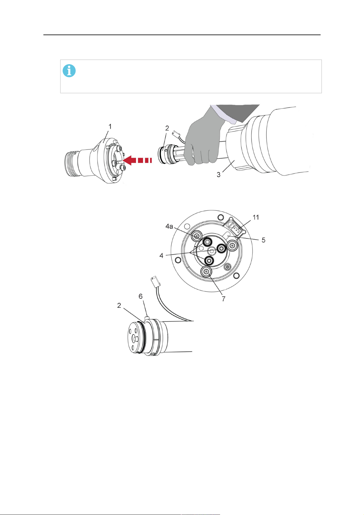
4.3.2.1 Držiak horáka RTKSC-2 G/W sbezpečnostným vypínacím mechanizmom
Polo
Popis Funkcia
žka
1 Podpera hrdla horáka Priechodka horáka Aristo RT
2 Kryt RTKSC-2 Zostava skáblom ahorákovými priechodkami
0463 373 101
- 17 -
© ESAB AB 2018

4 TECHNICKÉ ÚDAJE
Polo
Popis Funkcia
žka
3 Gumový chránič Ochrana bezpečnostného vypínacieho mechanizmu
4 Hlavné teleso RTKSC-2 Umožňuje mechanické odklonenie pri kolízii
5 Adaptérová obruba Oddeľovacia priechodka robotického zápästia (musí
byť vhodná pre konkrétneho robota)
6 Západkový kolík Na presné zarovnanie do adaptérovej obruby
7 Konektor pre kábel regulácie Elektrické pripojenie pre kolízny signál afunkciu
snímača dýzy
8 Mikrospínač Snímač detekcie kolízie
4.3.2.2 Pevný držiak horáka RTFLC-2 G/W
Polo
Popis Funkcia
žka
1 Podpera hrdla horáka Priechodka horáka Aristo RT
2 Kryt RTFLC-2 Zostava skáblom ahorákovými priechodkami
3 Hlavné teleso RTFLC-2 Umožňuje mechanické odklonenie pri kolízii
4 Západkový kolík Na presné zarovnanie do adaptérovej obruby
5 Adaptérová obruba Oddeľovacia priechodka robotického zápästia (musí
byť vhodná pre konkrétneho robota)
6 Konektor pre kábel regulácie
(3-pólový)
0463 373 101
Elektrické pripojenie funkcie snímača dýzy (v
prípade potreby)
- 18 -
© ESAB AB 2018

4 TECHNICKÉ ÚDAJE
4.4 Adaptérové obruby
Vyberte adaptérovú obrubu potrebnú pre inštaláciu na rameno robota vzávislosti od typu
robota. Kdispozícii sú adaptérové obruby pre všetky vhodné štandardné systémy asystémy
sdutým zápästím, pozrite si zoznam náhradných dielov.
4.5 Káblové zväzky
Pripojenie na podávač drôtu je ovplyvnené káblovým zväzkom, dostupnými verziami hlavne
vzávislosti od konštrukcie systému achladiacich médií (plyn alebo voda), pozrite si zoznam
náhradných dielov.
Menovité hodnoty platia pre dĺžky káblov od 1 do 5 m.
Štandardný káblový
Infiniturn Helix
zväzok
Menovité hodnoty
(10min. cyklus)
Chladenie plynom
(zmes plynov)
Menovité hodnoty
(10min. cyklus)
500A/60%
zaťažovací cyklus
350A/100%
zaťažovací cyklus
600A/100%
zaťažovací cyklus
400A/60%
zaťažovací cyklus
320A/100%
zaťažovací cyklus
550A/100%
zaťažovací cyklus
Chladenie vodou
Rozsah otáčania Obmedzená
otáčavosť
Hmotnosť
Chladenie plynom
Hmotnosť
Chladenie vodou
Dĺžka 1,2m:
2,35 kg
Dĺžka 1,2m:
2,35 kg
Neobmedzená
otáčavosť
Dĺžka 1,0m:
2,0 kg
Dĺžka 1,0m:
2,0 kg
4.5.1 Káblové zväzky pre štandardný systém RT
400A/60%
zaťažovací cyklus
320A/100%
zaťažovací cyklus
550A/100%
zaťažovací cyklus
±270° zneutrálne
polohy
Dĺžka 1,0m:
2,0 kg
Dĺžka 1,0m:
2,0 kg
0463 373 101
- 19 -
© ESAB AB 2018

4 TECHNICKÉ ÚDAJE
Kolíky konektora Burndy
A. Plynová dýza sdotykovým
snímačom
C. Kolízny snímač
F. 0V
G. + napätie motora
H. - napätie motora
D. Kolízny snímač
E. Posúvanie
Polo
Popis Funkcia
žka
1 Podperná obruba hrdla Priechodka horáka
2 Ochranný kryt Chráni káblový zväzok pred poškodením
3 Konektor Burndy, 12-pólový Elektrické prepojenie medzi bezpečnostným
vypínaním apodávačom drôtu
4 Kábel regulácie Pre KS-2 (bezpečnostné vypínanie atlačidlo)
5 Konektor EURO Pripojenie podávača drôtu
6 Vyfukovacia hadica (čierny
uzáver)
7 Prívod vody (modrý uzáver)
8 Spätný tok vody (červený
Na čistenie horáka stlačeným vzduchom po cykle
čistenia
Prívod vody na chladenie horáka
Spätný tok zohriatej vody od horáka
1
1
uzáver)
9 Zásuvka kábla regulácie
mechanizmu bezpečnostného
Elektrické prepojenie sRTKS-2 pre signál
bezpečnostného vypnutia afunkciu snímača dýzy
vypnutia
1
Len vodou chladené systémy horákov
4.5.2 Káblové zväzky pre systémy spriechodným zápästím
Káblový zväzok Infiniturn umožňuje otáčanie horáka voboch smeroch. Súčasne sa prenáša
chladiaca tekutina, ochranný plyn, vyfukovací vzduch, zvárací výkon asignál
bezpečnostného vypínacieho mechanizmu.
Káblový zväzok Helix je navrhnutý pre rozsah otáčania ±270° zneutrálnej polohy. Môže sa
používať na zváranie, ktoré nevyžaduje neobmedzené otáčanie.
Káblové zväzky Infiniturn sa dodávajú vo verziách schladením plynom achladením vodou.
Káblové zväzky Helix sa môžu univerzálne používať pre aplikácie schladením plynom alebo
chladením vodou.
POZOR!
Káblový zväzok Helix používaný pre hrdlo horáka schladením plynom nepripájajte
kvodnému chladiacemu systému.
0463 373 101
- 20 -
© ESAB AB 2018

4 TECHNICKÉ ÚDAJE
Polo
Popis Funkcia
žka
1 Obruba Držiak horáka RTKSC-2/priechodka RTFLC-2
2 Západkový kolík Zabezpečenie správnej orientácie pri spojení
3 Zásuvka kábla regulácie Elektrické prepojenie sRTKSC-2 pre signál
bezpečnostného vypnutia afunkciu snímača dýzy (v
prípade potreby)
4 Konektor EURO Pripojenie podávača drôtu
5 Kábel regulácie Elektrické prepojenie pre signál bezpečnostného
vypnutia (z RTKSC-2) afunkciu snímača dýzy
(snímač dýzy je štandardné vybavenie pre zväzky
Helix, nie pre zväzky Infiniturn)
6 Spätný tok vody (červený
Spätný tok zohriatej vody od horáka
uzáver)
7 Prívod vody (modrý uzáver) Prívod vody na chladenie horáka
8 Vyfukovacia hadica (čierny
Na čistenie horáka stlačeným vzduchom po zváraní
uzáver)
9 Spojka médií Neobmedzene otáčavá spojka na prenos médií
10 Ochranný kryt Chráni káblový zväzok pred poškodením
0463 373 101
- 21 -
© ESAB AB 2018

5 INSTALLATION
5 INSTALLATION
VÝSTRAHA!
For your own safety, make sure that the robot is either in standby or power-less
state before doing maintenance work in the moving radius of the robot.
Follow the assembly instructions exactly. Pay attention during assembly that the cables are
not damaged. Damaged cables can lead to a short circuit, which may damage the electronics
of the robot or the welding torch.
Use only original ESAB components that have been specially developed for this purpose.
Only then the correct functioning of the whole welding torch system can be guaranteed.
5.1 RTKS-2 standard arm installation
5.1.1 RTKS-2 safety-off mechanism
1. Dismount the insulation flange (10) from the RTKS-2 (11) by removing the screws
(12).
2. Position the insulation flange (10) with the index pin on the robot arm and fix it with the
screws (20) included.
The insulation flange (10) is directly compatible with robots with tool flange according
to DIN ISO 9409-1-A40 (diameter 40mm, 4×M6). If the insulation flange (10) does
not fit, use an adapter flange (21).
POZOR!
Ensure that the index pin is located correctly. The maximum torque of 1.2Nm
(10.5in.lb) must be observed for the fastening of the adapter flange screws.
Prevent self-loosening of the screws by using suitable thread locking
measures.
3. Mount the RTKS-2 the back on the insulation flange (10).
0463 373 101
- 22 -
© ESAB AB 2018

5 INSTALLATION
4. Position the mount on the RTKS-2 and carefully insert the cylindrical pins (14) into the
holes provided. Take the position of the torch into account. Two mounting positions
may be potentially possible.
5. Screw the mount evenly using the enclosed cylinder screws with hexagon socket (12).
POZOR!
The maximum tightening torque for the cylinder screw (5) is 6Nm (53in.lb)
and the property class category is 8.8.
12 - Cylinder screw with hexagon socket
M6DIN912 (length of the screw depending
on the torch mount)
14 - Cylindrical pins Ø4×20
5.1.1.1 Torch installation with adjustable mount
Torch mounts with a central clamping assembly can only be fastened on the journal of the
mounting flange. For this, the mounting flange must be fastened first.
1. If applicable, carefully press the cylindrical pins (1) into the corresponding holes in the
mounting flange. The pins should protrude by approximately 5 mm (0.2 in.).
2. Position the mount on the safety-off mechanism RTKS-2 and carefully insert the
cylindrical pins (1) into the holes provided. In doing so, take the later position of the
torch into account. Two mounting positions may be potentially possible.
3. Then screw down the mounting flange evenly using the enclosed cylinder screws with
hexagon socket (2).
POZOR!
The maximum tightening torque for the cylinder screw (2) is 7.1 Nm (62.8
in.lb) and the property class category is 8.8.
0463 373 101
- 23 -
© ESAB AB 2018

5 INSTALLATION
4. Unscrew the axial cylinder screw with hexagon socket (4) out of the mounting flange
together with the washer (3).
1 - Cylindrical pins Ø4×14 3 - Washer Ø9 mm
2 - Cylinder screw with hexagon socket
M6×16
4 - Axial cylinder screw with hexagon
socket M8×16
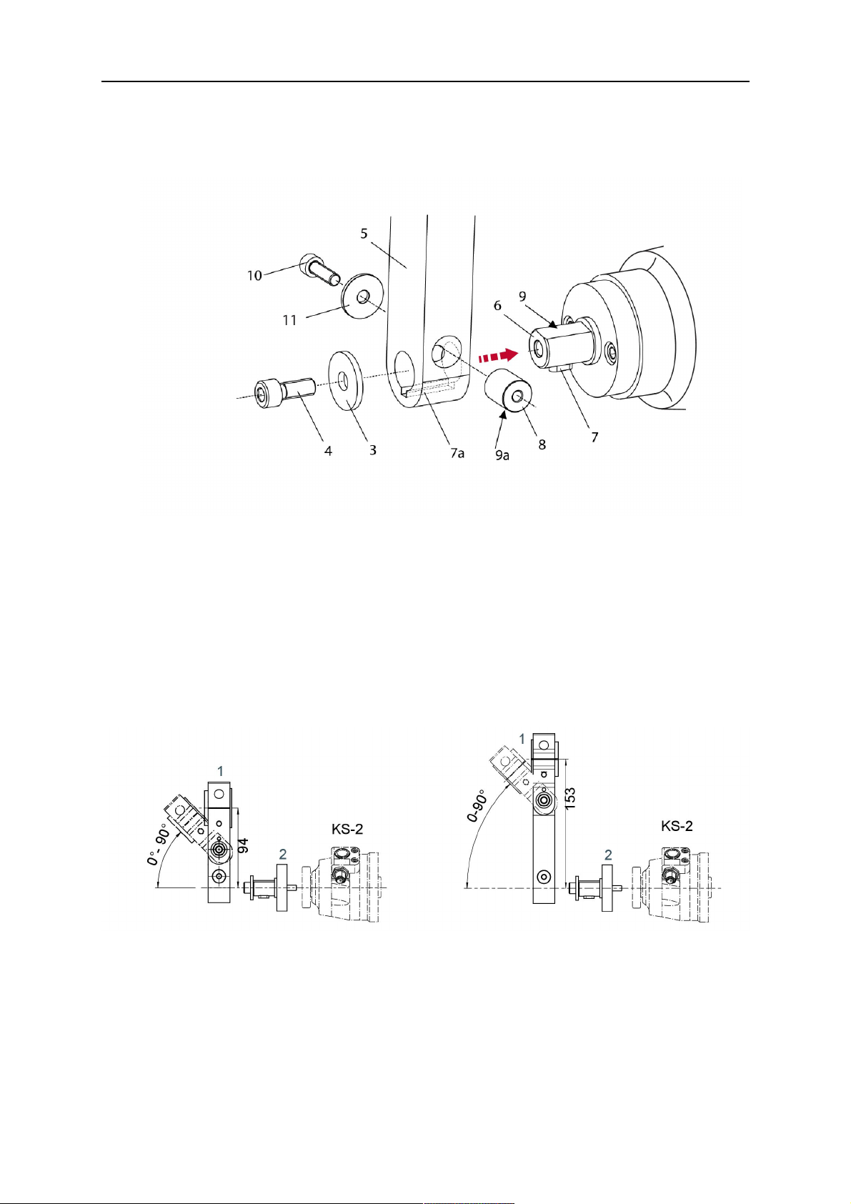
5. Place the torch mount (5) onto the journal (6) of the mounting flange, paying attention
while doing so to the exact alignment of the feather key (7) and the corresponding
groove (7a).
6. Insert the clamping mandrel (8) into the lateral hole (see illustration) and position it so
that the mating surfaces (9a) of the clamping mandrel rest on the mating surface (9) of
the journal.
0463 373 101
- 24 -
© ESAB AB 2018
5 INSTALLATION
7. Fix the clamping mandrel from the opposite side using the M6 cylinder screw with
hexagon socket (10) and the Ø22 mm washer (11).
8. Screw the axial cylinder screw (4) with the Ø9 mm washer (3) into the mounting flange
and tighten firmly.
3 - Washer Ø9 mm 8 - Clamping mandrel
4 - Axial cylinder screw with hexagon
9 - Mating surface of mounting flange
socket M8×16
5 - Torch mount 9a - Mating surfaces of clamping mandrel
6 - Mounting flange journal 10 - Cylinder screw with hexagon socket
M6×30
7 Feather key 11 - Washer Ø22×6.4 mm
7a - Groove for feather key
5.1.2 Standard arm cable assembly for KS-2 and FL-2
The cable assembly must be aligned to the intended use in length and design. The type of
cooling for the torch and the cable assembly must be the same (either gas or water cooled
respectively). In order to prevent damage to the torch system and other components, it is
imperative to observe the following instructions.
0463 373 101
- 25 -
© ESAB AB 2018
5 INSTALLATION
UPOZORNENIE!
• Coordinate the length and design of the cable assembly to suit the range of
action of the robot.
• Do not bend, compress or overstretch the cable assembly.
• Fix the cable assembly such that is can be moved freely and cannot become
entangled.
• Any additional holding devices possibly installed, for example a balancer,
must not crush or bend the cable assembly.
• Extreme turning movements must be avoided in which the cable assembly
may become twisted.
• Chafing on the robot or other objects must be excluded.
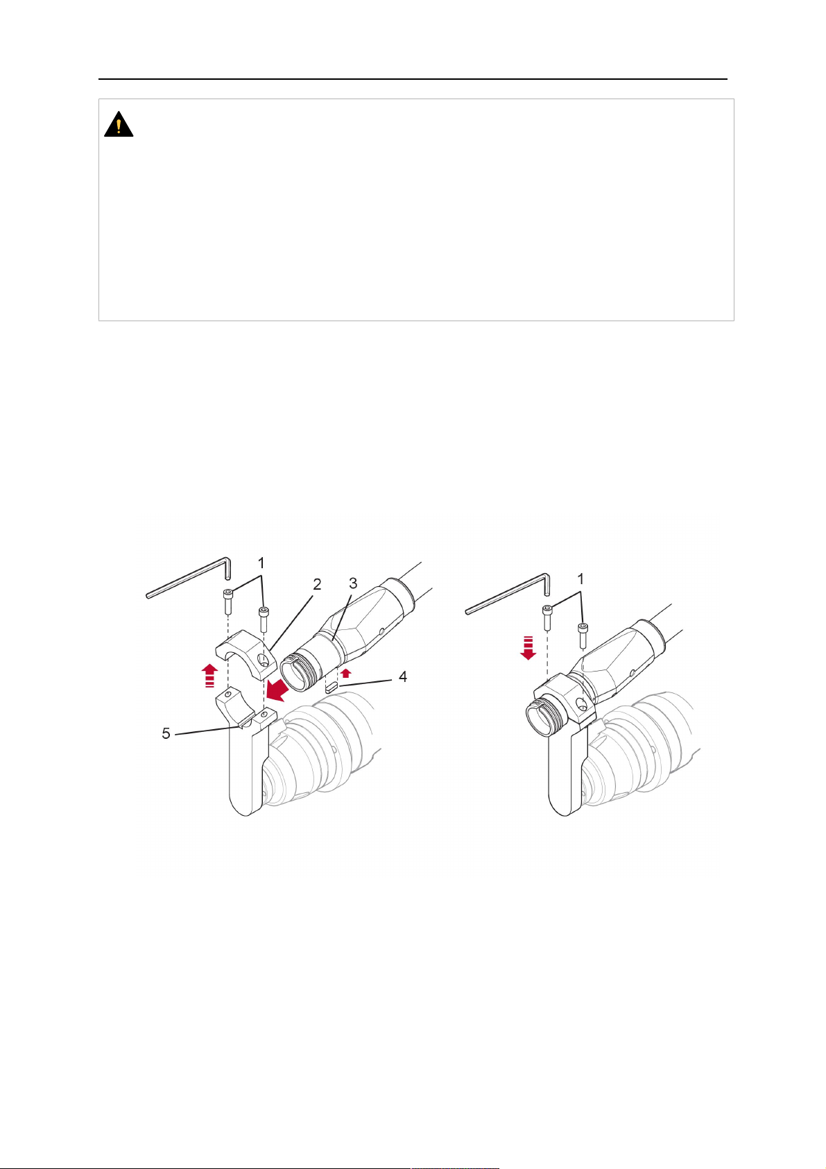
1. Unscrew the cylinder screws (1) and lift off the top section (2) of the torch mount.
2. Insert the feather key (4) into the recess of the neck support flange (3) from below.
3. Align the neck support flange (3) including the feather key (4) to the groove (5) of the
torch mount and push into the groove right up to the stop of the flange.
4. Hold the cable assembly in this position and simultaneously place the top section (2)
back onto the torch mount. First screw both cylinder screws (1) loosely in to about the
same length, then tighten alternately. The top section (2) of the mount should have an
even gap to the bottom section.
The front part of the cable assembly is directly clamped into the torch mount (see
illustration below).
1 - Cylinder screws 4 - Feather key
2 - Torch mount top section 5 - Groove for feather key
3 - Neck support flange
5.1.3 RTKS-2 wire feeder connection
In order to be able to create the connection, the cable assembly must be mounted as
described in the "Installing the cable assembly" section and equipped following "Installing the
wire guide" section. Only then can the central and media connection take place. Proceed as
described below:
0463 373 101
- 26 -
© ESAB AB 2018

5 INSTALLATION
1. Connect the central connector of the cable assembly (2) to the wire feeder cabinet
socket. Tighten the central connector sleeve nut fingertight. Do not use tools.
1 - Burndy Connector 4 - Return of heated water (red cap)
2 - EURO central connector 5 - Return of heated water (red cap)
3 - Air blow-out 6 - Main Wire feeder
2. For water cooled systems. Connect the water hoses to the cooling circuit. The end of
the hose marked blue (4) is connected to the water outlet, and the end marked red (5)
is connected to the water return.
3. Connect the blow-out line (3) to the corresponding connection of the feeder.
4. Connect the Burndy Connector to the wire feeder. (1) to the feeder. See section
"Electrical connections".
POZOR!
All hoses and the control line must be installed so they can not bend or get
damaged!
5.1.4 RTKS-2 electrical connections
5.1.4.1 RTKS-2 safety-off mechanism connection
The switch for the safety-off functionality RTKS-2 is connected through the control cable,
see (3) in the illustration below. This connects to the RTKS-2 unit via the 4-pole plug (4) that
contains circuits for the push-button (6) and the safety-off signal (7).
If a collision is detected, the control circuit for the safety-off signal (7), which is normally
closed, will be interrupted.
Rating of the control circuit: max. 48 V / 1 A
0463 373 101
- 27 -
© ESAB AB 2018

5 INSTALLATION
2 - Burndy connector 5 - RTKS-2 connector for control cable plug
4 - Control cable plug
Kolíky konektora Burndy
A. Plynová dýza sdotykovým
snímačom
C. Kolízny snímač
F. 0V
G. + napätie motora
H. - napätie motora
D. Kolízny snímač
E. Posúvanie
If the robot control provides a control circuit for nozzle sense functionality, the connection is
accomplished with a 1-wire connection.
Rating of the control circuit: max 50 V / 5 A.
NEBEZPEČENSTVO!
If the nozzle sense function is not being used, the open end of the control cable on
the power source connection side must be properly isolated in order to avoid short
circuits. During certain problems on the torch head, the full welding potential may be
present on this cable.
UPOZORNENIE!
After detection of contact (gas nozzle on work piece), quickly reduce or cut off the
maximum current in the nozzle sense circuit in order to avoid overloading of the
system.
Allowed load max. 1 minute at the rated nominal current.
5.1.5 RTKS-2 Torch installation
Continue according to section "Torch installation".
0463 373 101
- 28 -
© ESAB AB 2018
5 INSTALLATION
5.2 RTFL-2 standard arm installation
5.2.1 RTFL-2 rigid mount
1. Position the RT FL-2 (2) with the index pin on the robot arm and fix it with the hexagon
socket screw included.
The FL-2 is directly compatible with robots with tool flange according to DIN ISO
9409-1-A40 (diameter 40mm, 4×M6). If the rigid mount does not fit, use an adapter
flange (3).
POZOR!
Ensure that the index pin is located correctly. The maximum torque of 1.2Nm
(10.5in.lb) must be observed for the fastening of the adapter flange screws.
Prevent self-loosening of the screws by using suitable thread locking
measures.
2. Install torch mount (1). Only torch mounts having a hole pattern equivalent with the
mounting surface may be attached. If necessary, carefully press the cylindrical pins (4)
into the corresponding holes in the bracket. The pins should protrude by
approximately 5mm (0.2in.). Position the torch mount on the RTFL-2 (2) and
carefully insert the cylindrical pins (4) into the holes provided. Take the position of the
torch into account. Two mounting positions may be potentially possible.
3. Screw the mount evenly using the enclosed cylinder screws with hexagon socket (5).
POZOR!
The maximum tightening torque for the cylinder screw (5) is 6Nm (53in.lb)
and the property class category is 8.8.
0463 373 101
- 29 -
© ESAB AB 2018

5 INSTALLATION
4 - Cylindrical pins Ø4×20
5 - Cylinder screw with hexagon socket M6
DIN 912 (length of the screw depending on
the torch mount)
Side view
Torch installation with adjustable mount
Torch mounts with a central clamping assembly can only be fastened on the journal of the
mounting flange. For this, the mounting flange must be fastened first.
1. If applicable, carefully press the cylindrical pins (1) into the corresponding holes in the
mounting flange. Avoid the formation of burrs. The pins should protrude by
approximately 5 mm (0.2 in.).
2. Position the mount on the RTFL-2 and carefully insert the cylindrical pins (1) into the
holes provided. In doing so, take the later position of the torch into account. Two
mounting positions may be potentially possible.
3. Then screw down the mounting flange evenly using the enclosed cylinder screws with
hexagon socket (2).
POZOR!
The maximum tightening torque for the cylinder screw (2) is 7.1 Nm (62.8
in.lb) and the property class category is 8.8.
4. Unscrew the axial cylinder screw with hexagon socket (4) out of the mounting flange
together with the washer (3).
1 - Cylindrical pins Ø4×14 3 - Washer Ø9 mm
2 - Cylinder screw with hexagon socket
M6×16
4 - Axial cylinder screw with hexagon
socket M8×16
5. Place the torch mount (5) onto the journal (6) of the mounting flange, paying attention
while doing so to the exact alignment of the feather key (7) and the corresponding
groove (7a).
0463 373 101
- 30 -
© ESAB AB 2018

5 INSTALLATION
6. Insert the clamping mandrel (8) into the lateral hole (see illustration) and position it so
that the mating surfaces (9a) of the clamping mandrel rest on the mating surface (9) of
the journal.
7. Fix the clamping mandrel from the opposite side using the M6 cylinder screw with
hexagon socket (10) and the Ø22 mm washer (11).
8. Screw the axial cylinder screw (4) with the Ø9 mm washer (3) into the mounting flange
and tighten firmly.
3 - Washer Ø9 mm 8 - Clamping mandrel
4 - Axial cylinder screw with hexagon
9 - Mating surface of mounting flange
socket M8×16
5 - Torch mount 9a - Mating surfaces of clamping mandrel
6 - Mounting flange journal 10 - Cylinder screw with hexagon socket
M6×30
7 - Feather key 11 - Washer Ø22×6.4 mm
7a - Groove for feather key
5.2.2 RTFL-2 torch installation
Continue according to section "Torch installation".
5.3 RTKSC-2 hollow wrist system installation
5.3.1 RTKSC-2 mount with safety off mechanism
UPOZORNENIE!
For hollow wrist systems make sure that the clear space around the robot is at least
Ø45 mm (1.8 in.) around the wrist and 50 mm (2.0 in.) near the wire feeder.
0463 373 101
- 31 -
© ESAB AB 2018

5 INSTALLATION
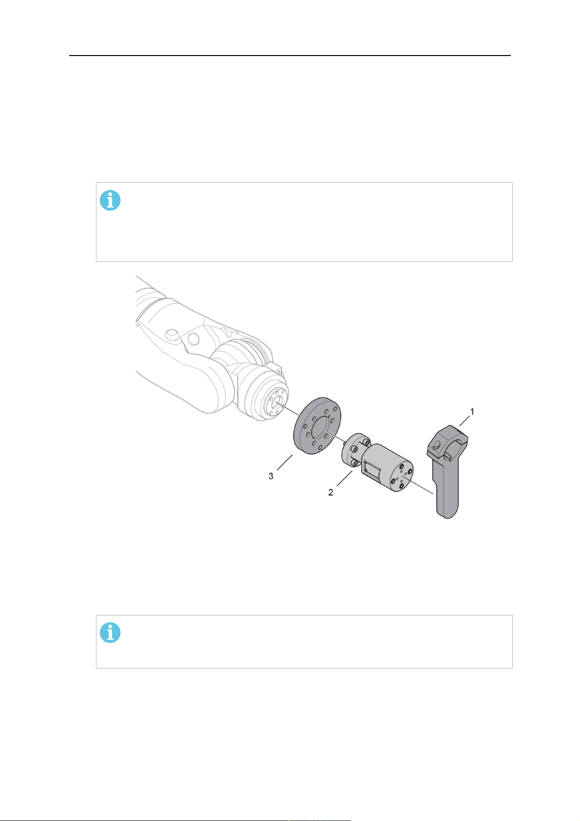
1. Remove the three screws (2) from the front cover (3) of the torch mount and carefully
pull the cover off the RTKSC-2 main body (5). Take care not to damage the micro
switches installed inside the assembly.
1 - Hexagon wrench 4 mm 4 - Rubber boot
2 - 3× M5×12 screws 5 - RT KSC-2 main body
3 - RT KSC-2 front cover
1. Pull off the rubber boot (4) from the RTKSC-2 main body (5) to the front.
2. Now position the RTKSC-2 main body (5) on the adapter flange (7) so that the index
pin is correctly seated. Attach with the screws (6) enclosed.
3. Reinstall the rubber boot (4) on the RTKSC-2 main body (5) and make sure it is
correctly located in the grooves on the front and back flange.
4. Istall the adapter flange (7) on the robot.
Fastening torque max. 2.2 Nm (19.5 in.lb).
1 - Hexagon wrench 4 mm 3 - 3× M5×12 hexagon socket screws
2 - Rubber boot 4 - Adapter flange
5.3.2 Mounting the cable assembly
POZOR!
In order to adjust the wire feeder position to the cable assembly length, it must be
mounted on an adjustable support with a possible movement of ±2-3cm (±1in.) to
the back and to the front. The length of the cable assembly must be determined
from the centred mounting position of the wire feeder.
1. Move the robot arm into a completely straight position, see illustration below. Make
sure that (1) axis 6 (rotation around the torch axis) is in 0° position.
2. Move the feeder (3) completely to the back in order to create space for inserting the
cable assembly. If it is not possible to move the feeder sufficiently, it should be
removed from the robot.
0463 373 101
- 32 -
© ESAB AB 2018

5 INSTALLATION
3. Insert the cable assembly with the coupling (2) first into the robot arm and feed it
through the robot wrist.
4. The feeder should only be installed again after the correct mounting position with
respect to the cable length has been determined. (See section "Installing the cable
assembly").
UPOZORNENIE!
Axis 6 must be in 0° position.
5.3.2.1 RTKSC-2 feeder cabinet connections
When installed for the first time, the position of the wire feeder cabinet must be adjusted to
the length of the cable assembly. First, the robot arm must be fully extended (straight).
UPOZORNENIE!
As long as the correct position of the feeder corresponding to the length of the cable
assembly has not been determined, be careful when moving the robot arm and
avoid overstretching the cable. It is helpful to loosen the positioning screws of the
feeder before moving the robot arm to allow the feeder to follow the cable assembly.
0463 373 101
- 33 -
© ESAB AB 2018

5 INSTALLATION
1. Loosen the sliding mechanism of the wire feeder and connect the cable assembly.
2. Now adjust the position of the wire feeder to suit the length of the Infiniturn or Helix
cable, as indicated with "A" in the illustration below.
UPOZORNENIE!
When adjusting the position of the feeder cabinet, make sure that the cable
assembly is not under stress when the robot arm is in stretched-out position.
It is normal for the cable assembly to sag slightly, it should never be taut.
3. Before securing the wire feeder in its permanent position, ensure that the Euro
connectors are tightly connected. Then turn the torch mount down and up again
(rotating on the axis 5), in order not to tighten the cable assembly too much against
the feeder (see illustration above). Once this is done, tighten the feeder in that
position.
4. For water cooled systems, connect the water lines to the cooling circuit. See section
"Cable assemblies for hollow wrist systems" in the TECHNICAL DATA chapter for
indications.
The hose with the blue rubber cap is for cooling water to the torch, the hose with the
red rubber cap returns the heated water. Make sure the hoses will not kink or get
otherwise blocked.
POZOR!
A Helix cable assembly used for a gas cooled system must not be connected
to a cooling circuit. As the water connections are not needed, they may be cut
off.
5. Connect the blow-out hose (black rubber cap) to the corresponding outlet of the wire
feeder.
POZOR!
If the blow-out function is not used, the blow-out hose must be sealed with the
rubber cap enclosed. With Infiniturn systems, the blow-out air must be
supplied to the corresponding connection hose, if it is not permitted to connect
blow-out air to the shield gas connection!
6. Install the necessary plug on the control cable and connect it to the safety off circuit
interface of the wire feeder (see section "Electrical connections").
0463 373 101
- 34 -
© ESAB AB 2018

5 INSTALLATION
5.3.3 RTKSC-2 cable assembly
The cable assembly must be aligned to the intended use in length and design. The type of
cooling for the torch and the cable assembly must be the same (either gas or water cooled
respectively). In order to prevent damage to the torch system and other components, it is
imperative to observe the following instructions.
UPOZORNENIE!
• Coordinate the length and design of the cable assembly to suit the range of
action of the robot.
• Do not bend, compress or overstretch the cable assembly.
• Fix the cable assembly such that is can be moved freely and cannot become
entangled.
• Any additional holding devices possibly installed, for example a balancer,
must not crush or bend the cable assembly.
• Extreme turning movements must be avoided in which the cable assembly
may become twisted.
• Chafing on the robot or other objects must be excluded.
5.3.3.1 RTKSC-2 cable assembly installation
POZOR!
For some robots, it may be possible to deviate from this order, and first connect the
cable assembly to the RTKSC-2, then thread the cable from the front through the
robot arm. If in doubt, follow the suggested order.
1. Loosen the three screws (7) with the associated washers and remove them from the
RTKSC-2 cover (1). See illustration below.
2. Install the supplied O-rings (4) into the grooves in the cover (1).
3. Pull the cable assembly approximately 15 cm (6 in.) from the main body (3).
0463 373 101
- 35 -
© ESAB AB 2018

5 INSTALLATION
4. Insert the coupling (2) into the socket of the cover (1) as shown. Align the index pin (6)
with the index hole (5) in the main body and insert completely.
POZOR!
Make sure that the position of the O-rings are not shifted by the index pin
during the assembly.
1 - RTKSC-2 cover 5 - Index hole
2 - Coupling 6 - Index pin
3 - RTKSC-2 main body 7 - 3× M5×35 screws
4 - 3× O-ring for water cooled systems 11 - Control cable connector
5. Insert the three screws (7) with the associated washers (8) and tighten gently with the
enclosed hexagonal wrench, see below illustration.
Fastening torque approximately 2 Nm (18 in.lb).
0463 373 101
- 36 -
© ESAB AB 2018

5 INSTALLATION
6. If present, insert the control cable plug (10) into the connector (11) and make sure it is
firmly seated.
7 - 3× M5×35 screw 11 - Control cable connector
8 - Washer 12 - 2× Micro switch
10 - Control cable plug 13 - Index pin
7. Gently push back the cable assembly into the robot arm and carefully seat the
RTKSC-2 cover (1) in place. Observe the index pin (13) to be in the correct position.
Make sure the two micro switches (12) are not damaged if present.
8. Insert the three M5 screws (14) and tighten without excessive force.
13. Index pin
14. 3× M5×12 screws
0463 373 101
- 37 -
© ESAB AB 2018

5 INSTALLATION
5.3.3.2 RTKSC-2 electrical connections
POZOR!
After connecting the control cable, secure the cable in order to protect it from getting
caught while the robot is moving.
Usually, the control cable will be directly connected to the wire feeder. See the
manufacturer's documentation for details. The link to the robot control is then
implemented via the power source controller.
RTKSC-2 safety-off mechanism connection
The switch for the safety-off functionality RTKSC-2 is connected through the control cable,
see (3) in the illustration below. This connects to the RTKSC-2 unit via the control cable plug
(1).
The safety-off signal requires a 2-wire connection (black/black) to the safety-off circuit in the
robot control (5).
If a collision is detected, the control circuit (normally closed) will be interrupted (4).
Rating of the control circuit: max. 48 V / 1 A.
1 - Control cable plug 3 - Burndy connector VVV
2 - EURO central connector
Kolíky konektora Burndy
A. Plynová dýza sdotykovým
snímačom
C. Kolízny snímač
F. 0V
G. + napätie motora
H. - napätie motora
D. Kolízny snímač
E. Posúvanie
RTKSC-2 nozzle sense function connection
If the robot control provides a control circuit for nozzle sense functionality.
The connection is accomplished with a 2-wire connection (black/black) to the nozzle sense
circuit in the robot control (5), see illustration below.
0463 373 101
- 38 -
© ESAB AB 2018

5 INSTALLATION
Usually, the control cable will be directly connected to the wire feeder. See the
manufacturer's documentation for details. The link to the robot control is then implemented
via the power source robot interface.
Rating of the control circuit: max. 50 V / 5 A.
NEBEZPEČENSTVO!
If the nozzle sense function is not being used, the open end of the control cable on
the power source connection side must be properly isolated in order to avoid short
circuits. During certain problems on the torch head, the full welding potential may be
present on this cable.
UPOZORNENIE!
After detection of contact (gas nozzle on work piece), quickly reduce or cut off the
maximum current in the nozzle sense circuit in order to avoid overloading of the
system.
Allowed load max. 1 minute at the rated nominal current.
1 - Control cable plug 3 - Control cable
2 - EURO central connector
5.3.4 RTKSC-2 torch installation
Continue according to section "Torch installation".
0463 373 101
- 39 -
© ESAB AB 2018

5 INSTALLATION
5.4 RTFLC-2 installation
5.4.1 RTFLC-2 mount
1. Remove the three M5 screws (2) from the front cover (3) of the RT FLC-2 torch mount
and carefully pull the cover off the main body (4).
1 - Hexagon wrench 4 mm 3 - RT FLC-2 front cover
2 - 3× M5×12 screws 4 - RT FLC-2 main body
2. Now position the RT FLC-2 main body (4) on the adapter flange (6) so that the index
pin is correctly seated. Attach with the screws (5) enclosed
Fastening torque max. 2.2 Nm (19.5 in.lb).
1 - Hexagon wrench 4 mm 5 - 3× M5×12 hexagon socket screws
4 - RT FLC-2 main body 6 - Adapter flange
5.4.2 RTFLC-2 wire feeder connection
5.4.2.1 Feeding through the robot arm
POZOR!
In order to adjust the wire feeder position to the cable assembly length, it must be
mounted on an adjustable support with a possible movement of ± 2-3 cm (± 1 in.) to
the back and to the front. The length of the cable assembly must be determined
from the centred mounting position of the wire feeder.
0463 373 101
- 40 -
© ESAB AB 2018

5 INSTALLATION
1. Move the robot arm into a completely straight position, see illustration below. Make
sure that (1) axis 6 (rotation around the torch axis) is in 0° position.
2. Move the feeder (3) completely to the back in order to create space for inserting the
cable assembly. If it is not possible to move the feeder sufficiently, it should be
removed from the robot.
3. Insert the cable assembly with the coupling (2) first into the robot arm and feed it
through the robot wrist.
4. The feeder should only be installed again after the correct mounting position with
respect to the cable length has been determined. (See section "Installing the cable
assembly").
UPOZORNENIE!
Important! Axis 6 must be in 0° position.
5.4.2.2 RTFLC-2 feeder cabinet connections
When installed for the first time, the position of the wire feeder cabinet must be adjusted to
the length of the cable assembly. First, the robot arm must be fully extended (straight).
UPOZORNENIE!
As long as the correct position of the feeder corresponding to the length of the cable
assembly has not been determined, be careful when moving the robot arm and
avoid overstretching the cable. It is helpful to loosen the positioning screws of the
feeder before moving the robot arm to allow the feeder to follow the cable assembly.
0463 373 101
- 41 -
© ESAB AB 2018

5 INSTALLATION
1. Loosen the sliding mechanism of the wire feeder and connect the cable assembly.
Refer to the instruction of the feeder manufacturer.
2. Now adjust the position of the wire feeder to suit the length of the Infiniturn or Helix
cable, as indicated with "A" in the illustration below.
UPOZORNENIE!
When adjusting the position of the feeder cabinet, make sure that the cable
assembly is not under stress when the robot arm is in stretched-out position.
It is normal for the cable assembly to sag slightly, it should never be taut.
3. Before securing the wire feeder in its permanent position, ensure that the Euro
connections are tightly connected. Then turn the torch mount down and up again
(rotating on the axis 5), in order not to tighten the cable assembly too much against
the feeder (see illustration above). Once this is done, tighten the feeder in that
position.
4. For water cooled systems, connect the water lines to the cooling circuit. See section
"Cable assemblies for hollow wrist systems" in the TECHNICAL DATA chapter for
indications.
The hose with the blue rubber cap is for cooling water to the torch, the hose with the
red rubber cap returns the heated water. Make sure the hoses will not kink or get
otherwise blocked.
POZOR!
A Helix cable assembly used for a gas cooled system must not be connected
to a cooling circuit. As the water connections are not needed, they may be cut
off.
5. Connect the blow-out hose (black rubber cap) to the corresponding outlet of the wire
feeder.
POZOR!
If the blow-out function is not used, the blow-out hose must be sealed with the
rubber cap enclosed. With Infiniturn systems, the blow-out air must be
supplied to the corresponding connection hose, if it is not permitted to connect
blow-out air to the shield gas connection!
0463 373 101
- 42 -
© ESAB AB 2018

5 INSTALLATION
6. Install the necessary plug on the control cable and connect it to the safety off circuit
interface of the wire feeder (see section "Electrical connections").
5.4.3 RTFLC-2 cable assembly
The cable assembly must be aligned to the intended use in length and design. The type of
cooling for the torch and the cable assembly must be the same (either gas or water cooled
respectively). In order to prevent damage to the torch system and other components, it is
imperative to observe the following instructions.
UPOZORNENIE!
• Coordinate the length and design of the cable assembly to suit the range of
action of the robot.
• Do not bend, compress or overstretch the cable assembly.
• Fix the cable assembly such that is can be moved freely and cannot become
entangled.
• Any additional holding devices possibly installed, for example a balancer,
must not crush or bend the cable assembly.
• Extreme turning movements must be avoided in which the cable assembly
may become twisted.
• Chafing on the robot or other objects must be excluded.
5.4.3.1 RTFLC-2 cable assembly installation
In a hollow wrist system the recommended order of installation is to feed the cable assembly
through the robot arm before connecting the cables to the torch mount.
When the cable assembly is correctly installed in the hollow wrist, continue the installation
according to the procedure described below.
POZOR!
For some robots, it may be possible to deviate from this order, and first connect the
cable assembly to the RTKSC-2 and RTFLC-2, then thread the cable from the front
through the robot arm. If in doubt, follow the suggested order.
1. Loosen the three screws (7) with the associated washers and remove them from the
RTFLC-2 cover (1). See illustration below.
2. Install the supplied O-rings (4) into the grooves in the cover (1). For gas cooled
systems, only one O-ring (4a) is needed, for water cooled systems all three O-rings
are needed.
3. Pull the cable assembly approximately 15 cm (6 in.) from the main body (3).
0463 373 101
- 43 -
© ESAB AB 2018
5 INSTALLATION
4. Insert the coupling (2) into the socket of the cover (1) as shown. Align the index pin (6)
with the index hole (5) in the main body and insert completely.
POZOR!
Take great care that the position of the O-rings is not shifted by the index pin
during the assembly.
1 - RT FLC-2 cover 5 - Index hole
2 - Coupling 6 - Index pin
3 - RT FLC-2 main body 7 - 3× M5×35 screws
4 - 3× O-ring for water cooled systems 11 - Control cable connector
5. Insert the three screws (7) with the associated washers (8) and tighten gently with the
enclosed hexagonal wrench, see below illustration.
Fastening torque approximately 2 Nm (18 in.lb).
0463 373 101
- 44 -
© ESAB AB 2018

5 INSTALLATION
6. If present insert the control cable plug (10) into the connector (11) and make sure it is
firmly seated.
7 - 3× M5×35 screw 11 - Control cable connector
8 - Washer 12 - 2× Micro switch
10 - Control cable plug 13 - Index pin
7. Gently push back the cable assembly into the robot arm and carefully seat the
RTFLC-2 cover (1) in place. Observe the index pin (13) to be in the correct position.
Make sure the two micro switches (12) are not damaged if present.
8. Insert the three M5 screws (14) and tighten without excessive force.
13 - Index pin 14 - 3x M5x12 screws
0463 373 101
- 45 -
© ESAB AB 2018

5 INSTALLATION
5.4.4 RTFLC-2 electrical connections
POZOR!
After connecting the control cable, secure the cable in order to protect it from getting
caught while the robot is moving.
Usually, the control cable will be directly connected to the wire feeder. See the
documentation of the manufacturer for details. The link to the robot control is then
implemented via the power source controller.
5.4.4.1 RTFLC-2 hollow wrist system with Infiniturn cable assembly
Connecting the nozzle sense function
If the robot control provides a control circuit for nozzle sense functionality.
The connection is accomplished with a 2-wire connection (black/black) to the nozzle sense
circuit in the robot control (5), see illustration below.
Usually, the control cable will be directly connected to the wire feeder. See the
manufacturer's documentation for details. The link to the robot control is then implemented
via the power source robot interface.
Rating of the control circuit: max. 50 V / 5 A.
NEBEZPEČENSTVO!
If the nozzle sense function is not being used, the open end of the control cable on
the power source connection side must be properly isolated in order to avoid short
circuits. During certain problems on the torch head, the full welding potential may be
present on this cable.
UPOZORNENIE!
After detection of contact (gas nozzle on work piece), quickly reduce or cut off the
maximum current in the nozzle sense circuit in order to avoid overloading of the
system.
Allowed load max. 1 minute at the rated nominal current.
1 - Control cable plug 3 - Control cable
2 - EURO central connector
0463 373 101
- 46 -
© ESAB AB 2018

5 INSTALLATION
5.4.4.2 RTFLC-2 hollow wrist system with Helix cable assembly
Connecting the nozzle sense function
If the robot control provides a control circuit for nozzle sense functionality.
The connection is accomplished with a 1-wire connection (green) to the nozzle sense circuit
in the robot control (5), see illustration below.
Usually, the control cable will be directly connected to the wire feeder. See the
manufacturer's documentation for details. The link to the robot control is then implemented
via the power source robot interface.
Rating of the control circuit: max. 50 V / 5 A.
NEBEZPEČENSTVO!
If the nozzle sense function is not being used, the open end of the control cable on
the power source connection side must be properly isolated in order to avoid short
circuits. During certain problems on the torch head, the full welding potential may be
present on this cable.
UPOZORNENIE!
After detection of contact (gas nozzle on work piece), quickly reduce or cut off the
maximum current in the nozzle sense circuit in order to avoid overloading of the
system.
Allowed load max. 1 minute at the rated nominal current.
1 - Control cable plug 3 - EURO central connector
2 - Control cable 4 - Burndy connector
5.5 Torch installation
Be sure to use the correct version of the torch mount and cable assembly (water or gas
cooled).
5.5.1 Torch neck equipment
The torch neck, see (1) in the illustration below, must always be equipped to suit the wire
diameter and material.
0463 373 101
- 47 -
© ESAB AB 2018

5 INSTALLATION
1. Select the correct wire guide, contact tip (4), tip holder (2), gas nozzle (5), and gas
diffuser/spatter protection (3). You will find an exact overview and possible alternative
equipment elements for various torch models in the spare parts list. Only use original
ESAB parts; only then is the fitting accuracy ensured.
2. Firmly tighten the tip holder and the contact tip using a suitable tool for example the
enclosed monkey wrench.
3. When using a split wire guide, remove the installed guide nipple including the o-ring
from the torch flange upon delivery if necessary (see section "Installing the neck
liner").
UPOZORNENIE!
The torch must be completely equipped before welding, especially the gas
diffuser and/or spatter protection and all necessary insulators have to be
installed according to the spare parts list. Welding without these items may
cause immediate destruction of the torch.
1 - Torch neck 4 - Contact tip
2 - Tip holder 5 - Contact tip
3 - Gas diffuser
5.5.2 Aristo RT torch neck installation
POZOR!
Check the O-rings on the flange of the torch neck before mounting. Replace the
O-rings if damaged or lost. Missing or faulty O-rings will lead to leaks of shielding
gas and coolant.
1. For hollow wrist systems, insert the torch into the torch mount in the correct
orientation, so that the locator pin fits into the slot of the RTKSC-2 or RTFLC-2
interface, see (A) in the illustration below. For standard systems, attach the torch to
the RT flange of the cable assembly, (B) in the illustration below.
Installation is only possible in the correct orientation.
2. Tighten the locking nut of the torch neck.
POZOR!
Only tighten by hand, never use tools or excessive force.
0463 373 101
- 48 -
© ESAB AB 2018

5 INSTALLATION
3. The correct seating of the torch can be checked by means of the window (1). If the
torch has been correctly mounted, no gap should be seen through the window (1).
5.6 Installing the wire guide for standard and hollow Wrist arm
Installing the wire guide
Choose the wire guide or liner depending on the filler wire material and diameter to be used,
see the spare parts list. Accurate performance of the system can only be guaranteed when
using original ESAB wire guides.
The recommended wire guide is the split wire guide, which consists of the neck liner and a
separate guide in the cable assembly. The front part of the wire guide, which is most
stressed, can be exchanged easily and independently of the cable assembly wire guide.
For correct installation, the following steps must be followed (example for Euro central
connector).
5.6.1 Installing the neck liner
The neck liner must be selected to fit the material and diameter of the welding wire, see the
spare parts list.
0463 373 101
- 49 -
© ESAB AB 2018

5 INSTALLATION
1. If present, remove the central guide nipple (1), from the torch neck using a hexagon
wrench (size 6 mm) or a large flat-blade screwdriver.
POZOR!
The guide nipple (1) can only be used with one-piece liners and must not be
used with the standard RT or hollow wrist system.
2. When replacing the neck liner:
Unfasten the sleeve nut and remove the torch neck.
Unfasten the liner nipple using a hexagon wrench (size 6 mm) and remove nipple and
liner from the torch neck.
3. Remove the gas nozzle and the contact tip.
4. Insert the new neck liner (2) into the torch. Carefully tighten the guide nipple using a
suitable tool, e.g. a hex-wrench (size 6 mm) or a large flat-blade screwdriver.
5. Cut the neck liner flush with the tip holder and remove the neck liner from the torch.
6. Install the contact tip.
7. Insert the neck liner again. It will be stopped by the contact tip. Measure the excess
liner sticking out of the neck.
8. Remove the liner again and shorten the front end by the measured length. Carefully
deburr the edge and make sure that the inner hole is not blocked.
9. Reinstall the neck liner and tighten the guide nipple in the neck.
5.6.2 Installing a split wire guide in the cable assembly
The correct liner must be inserted to suit the filler material and the wire diameter, see the
spare parts list.
The wire guide is inserted through the cable assembly from the rear, reaching the guide
nipple that is installed in the flange where the torch neck will be attached. The following
worksteps must be followed in order to correctly determine the wire guide length. (Example
for Euro central connector).
0463 373 101
- 50 -
© ESAB AB 2018

5 INSTALLATION
1. For standard RT system: Install the guide nipple (1) in the center hole of the neck
support flange, see illustration A below.
For hollow wrist system: Install the guide nipple (1) into the torch interface of the
RTKSC-2 / RTFLC-2 cover, see illustration B below.
2. Remove the sleeve nut (2) from the central connector, and remove the old wire guide.
3. Insert the wire guide through the central connection and push forwards as far as it will
go into the guide nipple (1), applying light pressure.
UPOZORNENIE!
Ensure that the wire guide has advanced right up to the stop at the front,
rotating and pushing forward gently.
4. Measure the excess length that needs to be cut from the wire guide.
5. Remove the wire guide again and shorten the front end by the measured length.
Steel liner: grind down the burred edges if needed.
Plastic liner: make a clean cut and chamfer the edges (e.g. with a pencil sharpener)
POZOR!
Make sure the inner opening of the liner is not obstructed by the cut wire end.
0463 373 101
- 51 -
© ESAB AB 2018

5 INSTALLATION
6. Reinstall the wire guide and attach the sleeve nut (2).
POZOR!
For hollow wrist systems where Infiniturn and Helix cable assemblies are
used, wire guides should be installed without tension so that the ends of the
liners may rotate freely.
Important note when using a plastic liner:
The wire channel between the drive rolls of the feeder and the central
connector of the torch must be fitted with a plastic liner. Depending on the
design of the feeder, a piece of plastic liner inserted into a brass guide tube
can be used.
During wire run-in, make sure that the wire is fed correctly into the plastic liner
of the torch. If necessary, remove the cable assembly from the feeder and
insert the wire, then reattach.
5.6.3 Installing a continuous wire guide in the cable assembly
Installing a steel liner
The wire guide is inserted through the cable assembly from the rear and reaches to the
contact tip. The following worksteps must be followed for the correct calculation of the length
(example for Euro central connector):
1. Install the torch (see section "Torch neck equipment").
2. Remove the gas nozzle and contact tip from the torch.
3. Remove the sleeve nut (D) from the Euro connector.
4. Push in the liner through the central connector and fix with the sleeve nut.
5. Cut off the liner flush with the nozzle holder. To determine the thread projection of the
contact tip, pull the liner backwards and screw in the contact tip.
6. Push the liner forwards as far as it will go to the contact tip applying light pressure on
the liner and measure the length to be shortened at the rear.
7. Now remove the liner again and cut the excess length measured off it’s front end. If
needed, grind down the burred edges. Make sure the inner opening of the liner is not
obstructed by the cut wire end.
8. The insulation of the liner must be removed after cutting off in the front area, such that
the insulation protrudes out of the RM2 flange by approx. 5 cm. For this, briefly
remove the torch neck.
9. Push the liner back in again and fix with the sleeve nut (D), see above. Re-install the
gas nozzle.
0463 373 101
- 52 -
© ESAB AB 2018

5 INSTALLATION
Installing a plastic liner
1. Mount the torch neck (see section "Torch neck equipment") and equip it with a gas
nozzle and contact tip.
2. Remove the sleeve nut (D) from the Euro connector.
3. Cleanly cut off the liner, slightly break the outer edges, point slightly (e.g. with a pencil
sharpener).
4. Insert the liner through the central connector into the cable assembly with fitted torch.
If it gets stuck, rotate the liner to free it and facilitate installation.
POZOR!
Make sure the liner is completely inserted by rotating it and slightly pushing it
forward, until you can feel it has reached its stop.
5. Mount the nipple (B) and the O-Ring (C), move it to the right position and fix it with the
sleeve nut (D) of the Euro central connector.
6. Measure the required overlap needed inside the wire feeder cabinet and cut the liner
accordingly.
5.7 Adjust the narrow gap contact tip
The adjusting tool RT42-NG is designed for the narrow gap torch necks RT42W-NG,
RT42G-NG and RT 82W-0°NG, torches with curved narrow gap contact tip. It facilitates the
precisely repeatable and fast changing of the curved contact tip.
POZOR!
The adjusting tool must be securely fastened to a stable base, in order to prevent
the position of the device in relation to the robot cannot change unintentionally. If the
exact orientation of the device is lost, the alignment of the contact tip used for the
elaboration of the welding programs can no longer be reproduced with precision.
Select a position within the operating range of the robot for orientation (alignment) of the
contact tip to the torch. Fasten the adjusting tool firmly to a base using the fastening grooves
provided for this purpose. Fastening material is not included with the adjusting tool. Select
fastening material (screws) to suit the existing conditions.
Save all motion sequences and stop positions required to change or align the wearing parts
to a separate robot program.
Before programming the welding tasks: plan at which orientation the contact tip is to stand in
relation to the torch. The torch must then be positioned in the desired rotational position and
the contact tip aligned using the adjusting device. Only then may the welding task be
programmed. If different orientations of the contact tip are required for various welding tasks,
the contact tip has to be aligned to the new position when the welding task is changed.
VÝSTRAHA!
The gas nozzle and the torch head become very hot during welding. Always allow
the torch to cool down before replacing wearing parts or adjusting the contact tip.
0463 373 101
- 53 -
© ESAB AB 2018

5 INSTALLATION
Adjust the contact tip
Move the robot torch to a position parallel to
the opening of the adjusting tool (2). Maintain
a sufficient distance to the work table to be
able to comfortably remove the gas nozzle.
Define this position in your robot program as
the wearing parts change position (stop
position 1).
Remove the gas nozzle by pulling it
downwards. Remove the welding wire in the
contact tip if necessary.
Loosen the counter nut (4) of the contact tip
while counter-holding the nozzle holder at the
wrench flat (3).
Unscrew the contact tip including the counter
nut from the nozzle holder and replace the
nozzle holder if necessary.
Completely screw the counter nut (4) onto the
new contact tip. Screw the contact tip
including the counter nut into the nozzle
holder.
Align the contact tip until it is parallel to the
opening of the adjusting tool. If necessary,
slightly unscrew the contact tip so that it can
be easily turned in both directions.
0463 373 101
- 54 -
© ESAB AB 2018

5 INSTALLATION
POZOR!
The contact tip must be able to be
easily moved by hand in both
directions in order to enable the
threading of the adjusting tool.
Place the robot torch or contact tip directly in
front of the opening of the adjusting tool (2)
(stop position 2).
Insert it slowly from the front until it is
completely inserted into the device (stop
position 3).
The contact tip was aligned exactly in the
device during insertion. Now cautiously
tighten the counter nut (4) in this position,
while counter holding the nozzle holder at the
wrench flat.
Slowly move the robot torch out of the
adjusting gauge, return to stop position 1 and
push on the gas nozzle as far as it will go.
Allow the welding wire to run into the contact
tip and bring the robot arm into welding
position.
0463 373 101
- 55 -
© ESAB AB 2018

6 OPERATION
6 OPERATION
UPOZORNENIE!
Before starting the system, check the whole installation according to the
manufacturer's instructions and applicable safety regulations.
Check the following to make sure that the system has been installed correctly:
1. Are all parts securely attached (torch, torch mount, flanges, safety-off device, cable
assembly, and wire feeder cabinet)?
2. Are all media hoses connected correctly and protected from damage?
3. Is the EURO central connector or direct connector fastened tightly?
4. Is the cable assembly length correct and suitable for the installation and can the cable
rotate freely? The cable must not be bent sharply. Any risk of the cable getting caught
on another object must be eliminated.
5. Is the control cable of the safety-off circuit connected and functioning? Move torch by
hand to test (RTKSC-2 and RTKS-2 only).
6. Is the torch firmly attached and is it completely equipped?
7. Is the wire guide installed according to the manual?
8. Are all lines and tubes arranged so that they cannot be damaged or bent?
The wire run-in can now be started, either via the wire run-in pushbutton or via the wire run-in
at the feeder.
6.1 Important information for programming (hollow wrist system only)
Fast rotation of axis 6 of the robot will significantly stress the cable assembly. In certain
cases, this can lead to damage or destruction of the cable. In order to maximize the lifetime
of the cable, we strongly suggest respecting the following limitations when programming the
robot.
Position of axis 5 Max. rotational speed of axis 6
0 – 60° 100 % (no limitations)
60° – 80° 300°/sec (approximately 50 % of max. robot speed)
> 80° 120°/sec (approximately 20 % of max. robot speed)
POZOR!
The above values are only indications. For information on the exact rotational speed
limits, refer to the individual robot manual or contact the robot supplier.
To reposition the torch quickly, the robot arm may have to be slightly extended first to achieve
a bending angle of max. 60° of axis 5. In this position, the maximum available rotation speed
of axis 6 can be used.
When using the ESAB Helix cable assembly, the max. rotation of ±270° from the neutral
position must not be exceeded.
0463 373 101
- 56 -
© ESAB AB 2018

6 OPERATION
UPOZORNENIE!
While axis 5 is bent more than 60°, the rotational speed of the torch around axis 6
must be limited, see table above.
Otherwise, the cable assembly may be damaged.
0463 373 101
- 57 -
© ESAB AB 2018

7 SERVIS A ÚDRŽBA
7 SERVIS A ÚDRŽBA
VÝSTRAHA!
Pred údržbou systému sa musí vypnúť hlavné napájanie zariadenia. Dodržiavajte
bezpečnostné predpisy uvedené na začiatku tejto príručky.
Poškodené horáky alebo káble sa nesmú používať! Známe chyby musí opraviť
kvalifikovaný personál pred ďalším používaním zariadenia.
VÝSTRAHA!
Riziko popálenia! Plynová dýza ahlava horáka sa počas zvárania veľmi zohrievajú.
Pred údržbovými prácami nechajte horák vychladnúť.
VÝSTRAHA!
Postupujte podľa nasledujúcich pokynov, aby sa predišlo zraneniam alebo
poškodeniu inštalácie:
1. Opravy držiaka horáka RTKSC-2 alebo RTFLC-2, bezpečnostného
vypínacieho mechanizmu RTKS-2, káblového zväzku aspojky médií
Infiniturn smie vykonávať iba servisná podpora spoločnosti ESAB.
2. Spojka médií Infiniturn sa nesmie nikdy otvoriť. Neobsahuje žiadne časti,
ktoré by mohol opravovať používateľ, ademontážou sa zničí.
3. Nikdy nedemontujte RTKSC-2 alebo RTKS-2. Je to pružinový
mechanizmus. Nesprávna manipulácia môže viesť kvážnemu zraneniu.
7.1 Povinné kontroly aopatrenia
Pred každým použitím:
• Skontrolujte horák, kontaktný hrot, plynovú dýzu, vložku do hrdla, káble acelkové
vybavenie, či nie sú všeobecne poškodené.
POZOR!
Scieľom minimalizovať prestoje sa odporúča striedať medzi dvoma hrdlami horáka
a vždy mať pripravené nové vybavené hrdlo horáka pripravené na použitie.
Každých 8hodín používania (v závislosti od aplikácie):
• Vymeňte kontaktný hrot.
Denne:
• Ručne vykonajte kontrolu funkcie bezpečnostného vypínacieho mechanizmu.
• Vykonajte vizuálnu kontrolu poškodenia – napríklad ohnutia alebo prasknutia.
• Skontrolujte správnu polohu podávača drôtu. Káblový zväzok nesmie byť veľmi
napnutý ani prehnutý.
• Skontrolujte tesnosť pripojenia médií aspojky médií Infiniturn.
• Vykonajte čistenie aúdržbu horáka podľa príručky pre horák.
Každých 40hodín používania (v závislosti od aplikácie):
• Vymeňte vložky vedenia drôtu.
• Vymeňte vložky do hrdla.
Týždenne alebo podľa potreby vzávislosti od používania:
0463 373 101
- 58 -
© ESAB AB 2018

7 SERVIS A ÚDRŽBA
• Vyberte vedenie drôtu askontrolujte, či nie je opotrebované aznečistené nánosmi. V
prípade potreby vymeňte.
Mesačne alebo častejšie vprípade náročného požívania (napríklad viac ako
8hodín/denne):
• Vyfúkajte kanál vedenia drôtu stlačeným vzduchom (vyberte kontaktný hrot avedenie
drôtu).
• Skontrolujte, či sú všetky skrutky utiahnuté.
• Skontrolujte všetky prepojenia ahadice, či nie sú poškodené.
• Po 250kg zváracieho drôtu vymeňte.
Vprípade poškodenia elektrickej izolácie musí opravu vykonať vyškolený personál. Systém
sa bude môcť bezpečne používať až po oprave.
0463 373 101
- 59 -
© ESAB AB 2018

8 RIEŠENIE PROBLÉMOV
8 RIEŠENIE PROBLÉMOV
Porucha Možná príčina Úkon
Nie je možné
privádzať drôt
Zvárací drôt nebol vyrovnaný pred
zavedením do káblového zväzku
Horák akáblový zväzok nie sú
správne vybavené pre priemer drôtu
amateriál drôtu
Vedenie drôtu nie je správne
vložené do káblového zväzku
Kontaktný hrot je zablokovaný
drôtenými úlomkami
Vedenie drôtu je opotrebované
Podávač drôtu je vhoráku
zablokovaný nečistotami
aúlomkami
Vprípade potreby zvárací drôt
znovu vytiahnite, koniec odrežte,
zbavte ostrín avyrovnajte prvých
10cm drôtu. Potom drôt navlečte
späť do káblového zväzku.
Skontrolujte vedenie drôtu (káblové
zväzky ahrdlo) akontaktný hrot.
Mierne vytiahnite vedenie drôtu
zkonektora Euro. Pri vkladaní
vedenia drôtu by ste mali pocítiť, že
posledné centimetre sa zasúvajú do
vodiacej vsuvky vpriechodke
horáka. Vopačnom prípade môže
byť vedenie drôtu príliš krátke anie
je úplne zasunuté.
Vymeňte kontaktný hrot a/alebo
vedenie drôtu, prefúkajte hrdlo
horáka, kanál vedenia drôtu
avedenie drôtu stlačeným
vzduchom.
Horák sa
nadmerne
zohrieva
Problémy
spodávaním
drôtu
Kontaktný hrot alebo držiak hrotu
nie sú správne utiahnuté
Použite vhodný nástroj na
utiahnutie rukou.
Chladiaci systém správne nefunguje Skontrolujte prietok vody, hladinu
naplnenia ačistotu vody.
Chladiaci systém nie je správne
pripojený
Skontrolujte pripojenie (prívod
aodvod vody).
Horák je priveľmi zaťažovaný Dodržiavajte technické parametre,
vyberte iný typ.
Chybný káblový zväzok Skontrolujte káble, potrubia
aspojenia.
Kontaktný hrot je opotrebovaný Vymeňte kontaktný hrot.
Vložka je opotrebovaná/špinavá Skontrolujte vložku, vyfúkajte ju. V
prípade potreby vymeňte.
Používaný spotrebný materiál nie je
vhodný vzhľadom na priemer alebo
Skontrolujte zoznam náhradných
dielov.
materiál drôtu
Podávač drôtu nie je správne
nastavený
Káblový zväzok je ohnutý alebo
rozložený vpríliš malých
polomeroch
Skontrolujte valce podávania drôtu,
prítlak abrzdu cievky.
Skontrolujte, či káblový zväzok nie
je poškodený. Dá sa vložka
jednoducho zasunúť? Nainštalujte
podľa pokynov. Pozrite si časť
„Inštalácia káblového zväzku“.
0463 373 101
Drôt je znečistený Použite čistiacu plsť.
- 60 -
© ESAB AB 2018

8 RIEŠENIE PROBLÉMOV
Porucha Možná príčina Úkon
Počas zvárania
Cievka sdrôtom je prázdna Skontrolujte množstvo zváracieho
sa posuv drôtu
zastaví
Zablokovanie drôtu vkáblovom
zväzku
Drôt horí do kontaktného hrotu
alebo opotrebovaný kontaktný hrot
Proces zvárania
sa zastaví
Spustil sa bezpečnostný vypínací
mechanizmus.
Trhliny vzvare Vírenie plynu spôsobené
zachytením rozstreku.
Príliš malý alebo extrémne veľký
prietok plynu horákom
Porucha prívodu plynu Skontrolujte prietok amožný únik.
Vlhkosť alebo znečistenie drôtu či
obrobku
drôtu na cievke vpodávači drôtu.
Skontrolujte prívod drôtu (možno je
príliš rýchly), skontrolujte
znečistenie/zanesenie kontaktného
hrotu, prípadne vyčistite alebo
vymeňte kontaktný hrot.
Vymeňte kontaktný hrot.
Vyhľadajte body kolízie aodstráňte
ich. Skontrolujte, či na ovládacom
vedení nie je uvoľnený kontakt.
Vyčistite hlavu horáka, použite
plynový difuzér/ochranu proti
rozstrekovaniu.
Skontrolujte prietok pomocou
meracieho nástroja.
Skontrolujte drôt aobrobok, použite
menej tekutiny alebo inú tekutinu
proti rozstrekovaniu.
Oblúk nie je
stabilný
Kontaktný hrot je opotrebovaný Vymeňte kontaktný hrot.
Nesprávne parametre zvárania Skontrolujte nastavenie zváracieho
zariadenia.
Nevyhovujúce elektrické prepojenia
vobvode
Skontrolujte, či sú všetky prepojenia
(vrátane uzemňovacieho kábla)
medzi zdrojom napájania, horákom
aobrobkom pevné.
0463 373 101
- 61 -
© ESAB AB 2018

9 OBJEDNÁVANIE NÁHRADNÝCH DIELOV
9 OBJEDNÁVANIE NÁHRADNÝCH DIELOV
UPOZORNENIE!
Opravy a elektrické práce musí vykonávať autorizovaný servisný technik ESAB.
Používajte len originálne náhradné diely ESAB.
Horáky ESAB RT RTKS-2, RTFL-2, RT-KSC-2, RT-FLC-2, RT42, RT52, RT62, RT72,
RT82, RT42-NG aRT82WNG sú skonštruované atestované vsúlade seurópskymi
normami IEC/EN 60974-7. Povinnosťou servisnej jednotky, ktorá vykonala servisné práce
alebo opravy, je presvedčiť sa, že výrobok aj naďalej zodpovedá uvedeným normám.
Náhradné diely adiely podliehajúce opotrebovaniu si môžete objednať od najbližšieho
predajcu spoločnosti ESAB, pozrite si webovú lokalitu esab.com. Pri objednávaní láskavo
uvádzajte typ výrobku, výrobné číslo, označenie a číslo náhradného dielu podľa zoznamu
náhradných dielov. To uľahčí expedíciu a zaistí správnosť dodávky.
0463 373 101
- 62 -
© ESAB AB 2018

9 OBJEDNÁVANIE NÁHRADNÝCH DIELOV
0463 373 101
- 63 -
© ESAB AB 2018

ESAB AB, Lindholmsallén 9, Box 8004, 402 77 Gothenburg, Sweden, Phone +46 (0) 31 50 90 00
http://manuals.esab.com
For contact information visit esab.com
 Loading...