


RT Robo Welding Torch System
RTKS-2, RTFL-2, KSC-2, FLC-2, RT42, RT52,
RT62, RT72, RT82, RT42-NG, RT82WNG
Käyttöohjeet
0463 373 101 FI 20181227


SISÄLLYSLUETTELO
1
TURVALLISUUS .......................................................................................... 5
1.1 Symbolien selitykset .............................................................................. 5
1.2 Varotoimenpiteet .................................................................................... 5
2
TAKUU ......................................................................................................... 8
2.1 Aiotun käyttötarkoituksen kuvaus........................................................ 8
3
JOHDANTO ................................................................................................. 9
3.1 Hitsauspoltinjärjestelmien yleiskatsaus .............................................. 10
4
TEKNISET TIEDOT ..................................................................................... 12
4.1 Hitsauspolttimen kaula .......................................................................... 12
4.2 Nimellisjännite ........................................................................................ 13
4.2.1 Jäähdytyspiirin rajat.............................................................................. 13
4.3 Polttimen kiinnike................................................................................... 14
4.3.1 Polttimen pidikkeet RT-vakiojärjestelmään........................................... 14
4.3.1.1 RT KS-2 -turvamekanismi ................................................................. 15
4.3.1.2 RT FL-2 -välilaippa ............................................................................ 15
4.3.2 Polttimen pidikkeet onttorannejärjestelmään........................................ 15
4.3.2.1 RT KSC-2 G/W -polttimen pidike turvamekanismilla......................... 17
4.3.2.2 Jäykkä RT FLC-2 G/W -polttimen pidike ........................................... 18
4.4 Sovitinlaipat ............................................................................................ 18
4.5 Kaapelikokoonpanot .............................................................................. 19
4.5.1 RT-vakiojärjestelmän kaapelikokoonpanot ........................................... 19
4.5.2 Kaapelikokoonpanot onttorannejärjestelmiin........................................ 20
5
INSTALLATION............................................................................................ 22
5.1 RTKS-2 standard arm installation........................................................ 22
5.1.1 RTKS-2 safety-off mechanism............................................................. 22
5.1.1.1 Torch installation with adjustable mount............................................ 23
5.1.2 Standard arm cable assembly for KS-2 and FL-2 ................................ 25
5.1.3 RTKS-2 wire feeder connection........................................................... 26
5.1.4 RTKS-2 electrical connections ............................................................ 27
5.1.4.1 RTKS-2 safety-off mechanism connection ....................................... 27
5.1.5 RTKS-2 Torch installation .................................................................... 28
5.2 RTFL-2 standard arm installation ........................................................ 29
5.2.1 RTFL-2 rigid mount.............................................................................. 29
5.2.2 RTFL-2 torch installation ..................................................................... 31
5.3 RTKSC-2 hollow wrist system installation.......................................... 31
5.3.1 RTKSC-2 mount with safety off mechanism ........................................ 31
5.3.2 Mounting the cable assembly............................................................... 32
5.3.2.1 RTKSC-2 feeder cabinet connections .............................................. 33
5.3.3 RTKSC-2 cable assembly ................................................................... 35
5.3.3.1 RTKSC-2 cable assembly installation .............................................. 35
5.3.3.2 RTKSC-2 electrical connections....................................................... 38
0463 373 101 © ESAB AB 2018

SISÄLLYSLUETTELO
5.3.4 RTKSC-2 torch installation .................................................................. 39
5.4 RTFLC-2 installation.............................................................................. 40
5.4.1 RTFLC-2 mount................................................................................... 40
5.4.2 RTFLC-2 wire feeder connection......................................................... 40
5.4.2.1 Feeding through the robot arm.......................................................... 40
5.4.2.2 RTFLC-2 feeder cabinet connections............................................... 41
5.4.3 RTFLC-2 cable assembly .................................................................... 43
5.4.3.1 RTFLC-2 cable assembly installation ............................................... 43
5.4.4 RTFLC-2 electrical connections .......................................................... 46
5.4.4.1 RTFLC-2 hollow wrist system with Infiniturn cable assembly........... 46
5.4.4.2 RTFLC-2 hollow wrist system with Helix cable assembly................. 47
5.5 Torch installation.................................................................................... 47
5.5.1 Torch neck equipment .......................................................................... 47
5.5.2 Aristo RT torch neck installation........................................................... 48
5.6 Installing the wire guide for standard and hollow Wrist arm ............. 49
5.6.1 Installing the neck liner......................................................................... 49
5.6.2 Installing a split wire guide in the cable assembly................................ 50
5.6.3 Installing a continuous wire guide in the cable assembly..................... 52
5.7 Adjust the narrow gap contact tip ........................................................ 53
6
OPERATION ................................................................................................ 56
6.1 Important information for programming (hollow wrist system only) 56
7
HUOLTO JA KUNNOSSAPITO ................................................................... 58
7.1 Pakolliset tarkistukset ja toimet............................................................ 58
8
VIANMÄÄRITYS .......................................................................................... 60
9
VARAOSIEN TILAAMINEN ......................................................................... 62
Pidätämme oikeudet muuttaa erittelyjä ilman eri ilmoitusta.
0463 373 101 © ESAB AB 2018

1 TURVALLISUUS
1 TURVALLISUUS
1.1 Symbolien selitykset
Tässä oppaassa käytetyt symbolit on esitelty seuraavassa. Kun näet symbolin,
kiinnitä erityishuomiota ohjeisiin ja toimi huolellisesti.
VAARA!
Viittaa välittömiin vaaroihin, jotka voivat aiheuttaa välittömän vakavan
henkilövahingon tai kuoleman.
VAROITUS!
Viittaa mahdollisiin vaaroihin, jotka voivat aiheuttaa henkilövahingon tai
kuoleman.
VARO!
Viittaa vaaroihin, jotka voivat aiheuttaa lievän henkilövahingon.
VAROITUS!
Ennen kuin käytät laitetta, lue käyttöohjeet ja noudata
niitä. Noudata myös kaikissa laitteen merkinnöissä
annettuja ohjeita, työnantajan turvaohjeita sekä
käyttöturvallisuustiedotteita.
1.2 Varotoimenpiteet
ESAB-laitteiden käyttäjät ovat velvollisia huolehtimaan siitä, että kaikki laitteen käyttäjät ja
laitteen läheisyydessä työskentelevät noudattavat kaikkia asianmukaisia varotoimenpiteitä.
Varotoimenpiteiden täytyy täyttää tämäntyyppisiä laitteita koskevat vaatimukset. Seuraavia
suosituksia tulisi noudattaa työpaikkaa koskevien standardimääräysten lisäksi.
Kaikki työt on teetettävä koulutetulla henkilökunnalla, jotka ovat tutustuneet hyvin laitteen
toimintaan. Laitteen virheellinen käyttö voi aiheuttaa vaaratilanteen, joka voi vahingoittaa
käyttäjää ja laitteistoa.
1. Kaikkien laitetta käyttävien on tunnettava:
○ sen käyttö
○ hätäpysäytyspainikkeiden sijainnit
○ sen toiminta
○ oleelliset varotoimenpiteet
○ hitsaus ja leikkaus sekä muu laitteiston käyttö.
2. Käyttäjän on varmistettava:
○ että asiattomia henkilöitä ei ole laitteen työalueella, kun se käynnistetään
○ kukaan ei ole suojaamaton, kun kaari sytytetään tai hitsaus aloitetaan.
3. Työpaikan on oltava:
○ tarkoitukseen sopiva
○ vedoton.
0463 373 101
- 5 -
© ESAB AB 2018

1 TURVALLISUUS
4. Henkilökohtaiset suojavarusteet:
○ Käytä aina suositeltuja suojavarusteita, kuten suojalaseja, liekinkestäviä
suojavaatteita ja suojakäsineitä.
○ Älä käytä löysiä vaatteita, kuten huiveja, rannerenkaita tai sormuksia, jotka
voivat takertua tai aiheuttaa palovammoja.
5. Yleiset varotoimet:
○ Varmista, että maadoituskaapeli on kunnolla kytketty.
○ Suurjännitelaitteiden sähkötyöt saa suorittaa vain valtuutettu sähköasentaja.
○ Sammutusvälineiden täytyy olla selkeästi merkittyjä ja käden ulottuvilla.
○ Laitteen voitelua ja huoltoa ei saa suorittaa käytön aikana
VAROITUS!
Kaarihitsaus ja -leikkaus voivat aiheuttaa tapaturman sinulle ja muille. Ole
varovainen hitsatessasi ja leikatessasi.
SÄHKÖISKU – voi tappaa
• Asenna ja maadoita laite käyttöohjeen mukaisesti.
• Älä koske jännitteellisiin osiin tai elektrodiin paljain käsin tai kun
suojavarusteesi ovat kastuneet.
• Eristä itsesi työkappaleesta ja maasta.
• Varmista, että työasentosi on turvallinen.
SÄHKÖ- JA MAGNEETTIKENTÄT – voivat olla hengenvaarallisia
• Hitsaajien, joilla on sydämentahdistin, on keskusteltava lääkärin kanssa
ennen laitteen käyttöä. Sähkömagneettiset kentät voivat häiritä tahdistimen
toimintaa.
• Sähkömagneettisille kentille altistumisella voi olla myös muita vaikutuksia
terveyteen.
• Jotta sähkömagneettisille kentille altistuminen on mahdollisimman
vähäistä, noudata seuraavia ohjeita:
○ Sijoita elektrodi- ja työkaapelit yhdessä samalle puolelle vartaloosi
nähden. Kiinnitä ne teipillä, jos mahdollista. Älä asetu poltin- ja
työkaapeleiden väliin. Älä kierrä poltin- tai työkaapeleita vartalosi
ympärille. Pidä hitsausvirtalähde ja kaapelit mahdollisimman kaukana
vartalostasi.
○ Kiinnitä työkaapeli mahdollisimman lähelle työkappaleen hitsattavaa
kohtaa.
HUURUT JA KAASUT – voivat olla hengenvaarallisia
• Pidä kasvosi poissa hitsaussavusta.
• Huolehdi ilmanvaihdosta ja käytä tarvittaessa imujärjestelmää, jotta höyryt
ja kaasut on mahdollista poistaa sekä hengitysvyöhykkeeltäsi että yleiseltä
oleskelualueelta.
KAAREN SÄTEILY – voi polttaa silmiä ja ihoa
0463 373 101
• Suojaa silmäsi ja kehosi. Käytä asianmukaista hitsausmaskia ja
suodatuslinssiä ja käytä suojavaatteita.
• Suojaa sivulliset sermeillä tai verhoilla.
MELU – voimakas melu voi vahingoittaa kuuloa
Suojaa korvasi. Käytä kuulonsuojaimia tai muuta kuulonsuojausta.
- 6 -
© ESAB AB 2018

1 TURVALLISUUS
LIIKKUVAT OSAT – voivat aiheuttaa tapaturman
• Pidä kaikki luukut, paneelit ja suojukset kiinni ja kunnolla paikallaan. Vain
pätevät henkilöt saavat irrottaa suojukset tarvittaessa huoltoa ja
vianmääritystä varten. Kun huolto on valmis, asenna paneelit tai suojukset
paikalleen ja sulje luukut ennen moottorin käynnistämistä.
• Sammuta moottori ennen yksikön asennusta tai liittämistä.
• Pidä kädet, hiukset, löysät vaatteet ja työkalut liikkuvien osien
ulottumattomissa.
PALOVAARA
• Kipinät (roiskeet) voivat aiheuttaa tulipalon. Varmista, että työpisteen
läheisyydessä ei ole syttyviä materiaaleja.
• Älä käytä laitetta suljettuihin säiliöihin.
TOIMINTAHÄIRIÖ – kutsu asiantuntija-apua toimintahäiriön yhteydessä.
SUOJAA ITSESI JA MUUT!
VARO!
Tämä tuote on tarkoitettu yksinomaan kaarihitsaukseen.
VAROITUS!
Älä käytä virtalähdettä jäätyneiden putkien sulattamiseen.
VARO!
Luokan A laitetta ei ole tarkoitettu käytettäväksi
kotitaloustiloissa, joiden jännite syötetään julkisella
pienjänniteverkolla. Näissä tiloissa luokan A laitteiden
sähkömagneettista yhteensopivuutta ei ehkä voida taata
johtuneiden ja säteiltyjen häiriöiden vuoksi.
HUOM!
Toimita sähkölaitteet sähköromun
keräyspisteeseen!
Sähkö- ja elektroniikkalaiteromua koskevan
EU-direktiivin 2012/19/EY ja kansallisen lainsäädännön
mukaan vanhentuneet sähkö- ja/tai elektroniikkalaitteet
on toimitettava keräyspisteeseen.
Laitteesta vastaavana henkilönä olet velvollinen
selvittämään hyväksytyt keruupisteet.
Lisätietoa saat lähimmältä ESAB-jälleenmyyjältä.
ESAB tarjoaa asiakkaiden ostettavaksi valikoiman hitsaustarvikkeita ja
henkilönsuojaimia. Tilaustiedot saat paikalliselta ESAB-jälleenmyyjältä tai
sivustoltamme.
0463 373 101
- 7 -
© ESAB AB 2018

2 TAKUU
2 TAKUU
Tuotteemme tarkastetaan huolellisesti ennen niiden toimittamista asiakkaille. ESAB takaa,
että tuotteessa ei ole toimitushetkellä materiaali- tai valmistusvikoja ja että se toimii
asianmukaisesti aiotussa käyttötarkoituksessaan.
ESAB antaa tuotteelle säädösten edellyttämän materiaali- ja valmistusvikoja koskevan
takuun. Tämä takuu ei koske kulutustarvikkeita.
Takuu ei koske vaurioita tai toimintahäiriöitä, joiden syy on:
• tuotteen ylikuormitus, väärinkäyttö tai käyttö muuhun kuin sen aiottuun
käyttötarkoitukseen
• törmäykset tai onnettomuudet
• näissä käyttöohjeissa kerrottujen ohjeiden noudattamatta jättäminen
• virheellinen asennus tai kokoonpano
• riittämätön huolto
• tuotteeseen tehty muutos
• kemikaalin aiheuttama vaikutus
• normaali kuluminen.
ESABin vastuu rajoittuu viallisten osien korjaamiseen tai vaihtamiseen.
2.1 Aiotun käyttötarkoituksen kuvaus
1. Tuote on tarkoitettu teolliseen ja kaupalliseen käyttöön, ja sitä saa käyttää vain
koulutettu henkilöstö. Valmistaja ei ole vastuussa virheellisen käytön aiheuttamista
vahingoista tai onnettomuuksista.
2. Aristo® RT -robottihitsausjärjestelmä on suunniteltu ja valmistettu huipputason
tekniikkaa käyttäen. Se on turvallinen ja luotettava käyttää, kun sen käsittelystä,
asennuksesta ja huollosta vastaa koulutettu henkilökunta. Tässä asiakirjassa
annettuja asennus-, käyttö- ja huolto-ohjeita on noudatettava.
3. Vain koulutettu henkilöstö saa asentaa Aristo® RT -robottihitsausjärjestelmän ja
käyttää ja huoltaa sitä. Tässä käyttöoppaassa mainittuja asennus-, käyttö- ja
huolto-ohjeita on noudatettava.
4. Aristo® RT -robottihitsausjärjestelmää saa käyttää vain valmistajan tarkoittamaan
käyttötarkoitukseen automatisoiduissa materiaalinkäsittelyjärjestelmissä järjestelmän
teknisten tietojen puitteissa. Polttimen tyyppi on valittava hitsaustehtävän mukaan.
5. Aristo® RT -robottihitsausjärjestelmä on tarkoitettu käytettäväksi kokonaisena
järjestelmänä. Muiden valmistajien komponenttien lisääminen järjestelmään ei ole
sallittua.
6. RT KS-2- ja RT KSC-2-mekanismeja saa käyttää ainoastaan teknisten tietojen
mukaisina hätäpysäytysmekanismeina ja yhdessä RT-vakiovarsikaapelikokoonpanon
(KS-2), Infiniturnin tai Helixin (KSC-2) ja ESAB-sovitinlaipan kanssa, mukaan lukien
RT-polttimen pidikkeet (KS-2) ja Aristo RT -hitsauspoltin.
7. Puhalluskaasuun ei saa lisätä öljyä eikä roiskeita estävää nestettä. ESAB ei takaa
kyseisten aineiden kemiallista kestävyyttä. ESAB suosittelee, että polttimeen lisätään
mahdollisimman vähän roiskeita estävää nestettä ESAB-ruiskutusyksikköä
käyttämällä, mikä suojaa ympäristöä.
8. Tuote on pidettävä kuivana ja suojattava kosteudelta kuljetuksen, käytön ja
varastoinnin aikana.
9. Järjestelmä on tarkoitettu tiloihin, joiden lämpötila on 5–40 °C (41–104 °F). Jos nämä
rajat ylittyvät, on ryhdyttävä erityistoimiin. Jos laite on vaarassa jäätyä, käytä
asianmukaista jäähdytysnestettä.
0463 373 101
- 8 -
© ESAB AB 2018

3 JOHDANTO
3 JOHDANTO
RT-hitsauspoltinjärjestelmät on tarkoitettu täysin automaattiseen, roboteilla suoritettavaan
MIG/MAG-hitsaukseen. Järjestelmät koostuvat erilaisista Aristo RT -polttimen kauloista, jotka
on suunniteltu robottikäyttöä varten, polttimen pidikkeistä, robottikäyttöön optimoiduista
kaapelikokoonpanoista ja turvaominaisuuksista, jotka estävät järjestelmää vahingoittumasta
törmäystilanteissa.
RT-vakiohitsausjärjestelmä suojaa törmäyksiä käyttämällä RT KS-2:ta, joka on mekaanisesti
jousikuormitteinen turvamekanismi. Sen voi myös korvata RT FL-2:lla, jolloin voidaan
hyödyntää robottiohjausjärjestelmän törmäyksen havaitsemistoimintoa.
RT-vakiohitsausjärjestelmää voidaan käyttää monien erilaisten kaapelikokoonpanotyyppien
kanssa.
RT KSC-2- ja RT FLC-2 -polttimen pidikkeet Infiniturn- tai Helix-kaapelikokoonpanoilla on
tarkoitettu käytettäväksi onttorannerobottihitsausjärjestelmissä, jotka on suunniteltu
vaativaan hitsaukseen. RT KSC-2 -polttimen pidikkeen turvamekanismi mahdollistaa
polttimen suuren elastisuuden törmäyksen sattuessa. Infiniturn- ja Helix-kaapelikokoonpanot
ovat helppoja asentaa, ja ne tarjoavat erittäin luotettavan järjestelmän, jossa on tarkat
ohjausominaisuudet.
Nämä ominaisuudet muodostavat yhdessä tunnettujen Aristo RT -robottihitsauspolttimien
kanssa erittäin luotettavan ja pitkäikäisen järjestelmän, joka tarvitsee vain vähän huoltoa.
Käyttöopas sisältyy polttimen pidikkeiden ja kaapelikokoonpanojen toimitukseen.
ESAB-tilausnumerot, saatavilla olevat lisävarusteet, varaosat ja kulutusosat ovat
varaosaluettelossa.
0463 373 101
- 9 -
© ESAB AB 2018

3 JOHDANTO
3.1 Hitsauspoltinjärjestelmien yleiskatsaus
RT-vakiojärjestelmä
Katso yksityiskohtainen kuvaus luvusta
TEKNISET TIEDOT:
1. Polttimen kaula
Katso kohta Hitsauspoltin.
2. Kaapelikokoonpano
Katso kohta RT-vakiojärjestelmän
kaapelikokoonpanot.
3. Polttimen kiinnike
Katso kohta RT-vakiojärjestelmän
polttimen pidikkeet.
4. RT KS-2 -turvamekanismi
Katso kohta RT KS-2
-turvamekanismi.
5. RT FL-2 -välilaippa
Katso kohta RT FL-2 -välilaippa.
6. Sovitinlaippa (tarvittaessa)
Katso kohta Sovitinlaipat.
0463 373 101
- 10 -
© ESAB AB 2018

3 JOHDANTO
Onttorannejärjestelmä
Katso yksityiskohtainen kuvaus luvusta
TEKNISET TIEDOT:
1. Polttimen kaula
Katso kohta Hitsauspoltin.
2. Polttimen pidike RT KSC-2
Katso kohta RT KSC-2 -polttimen
pidike turvamekanismilla.
3. Polttimen pidike RT FLC-2
Katso kohta Jäykkä RT FLC-2
-polttimen pidike.
4. Sovitinlaippa
Katso kohta Sovitinlaipat.
5. Kaapelikokoonpano Helix tai
Infiniturn
Katso kohta Onttorannejärjestelmien
kaapelikokoonpanot.
0463 373 101
- 11 -
© ESAB AB 2018

4 TEKNISET TIEDOT
4 TEKNISET TIEDOT
4.1 Hitsauspolttimen kaula
Valitse polttimen malli hitsauskohteen mukaan. Huomioon otettavia seikkoja ovat
kuormitusaikasuhde ja kapasiteetti, jäähdytysmenetelmä ja langan halkaisija. Mahdolliset
lisävaatimukset, esimerkiksi työkappaleiden esilämmitys tai kulmien aiheuttama voimakas
lämmön heijastuminen, on otettava huomioon hitsauspolttimen nimellistehoa valittaessa.
RT-hitsauspolttimet on tarkoitettu MIG-hitsaukseen, MAG-hitsaukseen sekä MIG-juottoon
vapaasti myytävillä pyöreillä hitsauslangoilla CE-hyväksyttyjen hitsausvirtalähteiden kanssa.
Älä käytä poltinta muihin käyttötarkoituksiin.
Teräs- tai alumiinihitsauksessa käytettävässä pulssikaarihitsauksessa on käytettävä
vesijäähdytteistä RT 82W -poltinta.
Katso saatavilla olevat poltinmallit alla.
Poltinmalli
JäähdytysmenetelmäSuojakaasu Nimellisarvo
RT42G Kaasujäähdytteinen CO
Kaasujäähdytteinen 300A / 100%
Kaasujäähdytteinen Sekoitus 350A / 60%
Kaasujäähdytteinen 250A / 100%
RT42W Vesijäähdytteinen CO
Vesijäähdytteinen 420A / 100%
Vesijäähdytteinen Sekoitus 350A / 60%
Vesijäähdytteinen 350A / 100%
RT52G Kaasujäähdytteinen CO
Kaasujäähdytteinen 300A / 100%
Kaasujäähdytteinen Sekoitus 350A / 60%
Kaasujäähdytteinen 250A / 100%
RT52W Vesijäähdytteinen CO
Vesijäähdytteinen 470A / 100%
Vesijäähdytteinen Sekoitus 400A / 60%
2
2
2
2
420A / 60%
420A / 60%
420A / 60%
470A / 60%
Vesijäähdytteinen 400A / 100%
RT62G Kaasujäähdytteinen CO
Kaasujäähdytteinen 340A / 100%
Kaasujäähdytteinen Sekoitus 420A / 60%
Kaasujäähdytteinen 290A / 100%
RT62W Vesijäähdytteinen CO
Vesijäähdytteinen 530A / 100%
Vesijäähdytteinen Sekoitus 450A / 60%
Vesijäähdytteinen 450A / 100%
0463 373 101
- 12 -
2
2
500A / 60%
530A / 60%
© ESAB AB 2018

4 TEKNISET TIEDOT
Poltinmalli
RT72G Kaasujäähdytteinen CO
JäähdytysmenetelmäSuojakaasu Nimellisarvo
2
480A / 60%
Kaasujäähdytteinen 320A / 100%
Kaasujäähdytteinen Sekoitus 400A / 60%
Kaasujäähdytteinen 270A / 100%
RT72W Vesijäähdytteinen CO
2
480A / 60%
Vesijäähdytteinen 430A / 100%
Vesijäähdytteinen Sekoitus 480A / 60%
Vesijäähdytteinen 430A / 100%
RT82W Vesijäähdytteinen CO
2
600A / 60%
Vesijäähdytteinen 600A / 100%
Vesijäähdytteinen Sekoitus 550A / 60%
Vesijäähdytteinen 550A / 100%
Polttimen nimellisarvot ja kuormitusaikasuhdearvot koskevat 10 minuutin jaksoa.
Tekniset tiedot koskevat normaalia käyttöä tavallisilla kulutus-/varaosilla. Polttimen
nimellisarvo pienenee metallin pulssikaarisiirtotilaa käytettäessä.
Lämpötila-alueet Varastointi: -15–50°C (5–122°F)
Käyttö: 5-40°C (41-104°F)
Puhalluskaasu Enint. 10 bar, erillinen kaasuletku
Kokonaispaino (polttimen kaula,
Noin 5 kg
turvamekanismi, polttimen pidike ja 1 metrin
kaapelikokoonpano)
4.2 Nimellisjännite
Suurin sallittu jännite/ampeerimäärä
Kokonainen hitsauspoltinjärjestelmä 141 V (hitsauksen huippuarvo)
RT KS-2 -turvakatkaisupiiri
RT KS-2 -painike
RT KSC-2 -turvakatkaisupiiri 48 V
Suuttimen tunnistustoiminnon käyttäminen
vakiokaapelikokoonpanon kanssa
Suuttimen tunnistustoiminnon käyttäminen
Helix- tai Infiniturn-kaapelikokoonpanon
kanssa
24 V / 1 A
48 V / 0,1 A
50 V / 5 A
(Suurin sallittu kuorma 1 minuutti
nimellisvirralla)
50 V / 5 A
(Suurin sallittu kuorma 1 minuutti
nimellisvirralla)
Ilmoitetut nimellisarvot vastaavat normaalia käyttöä.
Katso kaapelikokoonpanojen nimellisarvot kohdasta Kaapelikokoonpanot.
4.2.1 Jäähdytyspiirin rajat
Koskee vain vesijäähdytteisiä malleja.
0463 373 101
- 13 -
© ESAB AB 2018
4 TEKNISET TIEDOT
Veden vähimmäisvirtaus: 1,0 l/min
Veden vähimmäispaine: 2,5 bar (36,3 psi)
Suurin vedenpaine: 3,5 bar (50,8 psi)
Syöttölämpötila: Enintään 40 °C (104 °F)
Paluulämpötila: Enintään 60 °C (140 °F)
Jäähdytyskapasiteetti: Vähintään 1 000 W käyttötarkoituksen mukaan
VARO!
Jos veden paluulämpötila on yli 60 °C (140 °F), kaapelikokoonpano voi vaurioitua.
4.3 Polttimen kiinnike
Vaadittava polttimen pidiketyyppi määräytyy RT-hitsauspoltinjärjestelmän rakenteen ja
turvalaitteiden mukaan. Katso kohta Hitsauspoltinjärjestelmien yleiskatsaus.
Komponentti Arvioitu paino
Polttimen pidike (vakiojärjestelmä) 0,43 kg
RT KS-2 -turvamekanismi (vakiojärjestelmä) 0,85 kg
RT FL-2 -välilaippa (vakiojärjestelmä) 0,35 kg
RT KSC-2 -polttimen pidike
1,90 kg
(onttorannejärjestelmä)
Jäykkä RT FLC-2 -polttimen pidike
1,22 kg
(onttorannejärjestelmä)
Robottihitsauspoltin 0,66 kg
4.3.1 Polttimen pidikkeet RT-vakiojärjestelmään
RT-vakiojärjestelmissä polttimen pidike on asennettu RT KS-2 -turvamekanismiin
(vaihtoehtoisesti RT FL-2 -välilaippaan), ja se kiinnittää kaapelikokoonpanoon ja polttimen
kaulan.
Valitse polttimen pidikkeet polttimen tyypin ja geometrian mukaan. Laitteessa voi käyttää
monentyyppisiä pidikkeitä. Tarkista RT-vakiojärjestelmään saatavilla olevat polttimen
pidikkeet varaosaluettelosta.
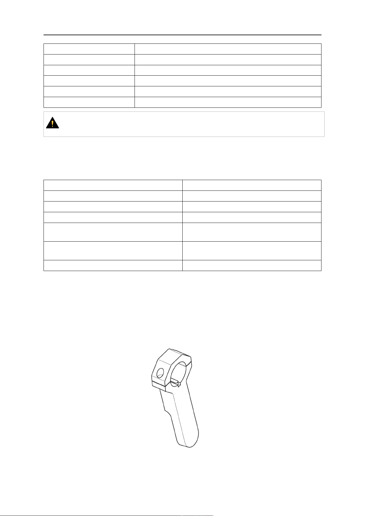
Polttimen pidike vakiovarsiroboteille
0463 373 101
- 14 -
© ESAB AB 2018

4 TEKNISET TIEDOT
4.3.1.1 RT KS-2 -turvamekanismi
RT KS-2 -turvamekanismi on jousiavusteinen laite, joka suojaa robottia ja poltinjärjestelmää
törmäystilanteissa.
HUOM!
Älä pura RT KS-2 -yksikköä.
4.3.1.2 RT FL-2 -välilaippa
Jäykkää välilaippaa RT FL-2 voi käyttää RT KS-2:n sijaan, jos robotissa on elektroninen
törmäyksen tunnistusjärjestelmä.
4.3.2 Polttimen pidikkeet onttorannejärjestelmään
Onttorannejärjestelmässä Aristo RT -hitsauspolttimen kaulat on liitetty polttimen
pidikkeeseen KSC-2 tai FLC-2.
Polttimen pidike RT KSC-2 mahdollistaa polttimen elastisen poikkeaman törmäyksen
sattuessa. Samaan aikaan avataan sähkökontakti, joka määrää robotin ohjauksen
pysähtymään. Kun virhe on korjattu, polttimen alkugeometria ja työkalukeskipiste (TCP)
saavutetaan erittäin tarkasti. Järjestelmä toimii täysin mekaanisesti ja on jousikuormitteinen.
Polttimen pidikkeessä RT FLC-2 ei ole sisäänrakennettua turvatoimintoa.
0463 373 101
- 15 -
© ESAB AB 2018

4 TEKNISET TIEDOT
Onttorannejärjestelmiin suositellaan pidikettä RT KSC-2 G/W (vaihtoehtoisesti RT FLC-2
G/W). Tätä polttimen pidikettä voi käyttää sekä kaasu- että vesijäähdytteisissä Aristo RT
-sarjan polttimissa.
RTKSC-2 G/W RTFLC-2 G/W
Turvamekanismin
toimintaperiaate
Aksiaalinen vapautusvoima
(Fz)
Irrotusmomentti
poikittaisakselilla (Mx)
Palautus alkutilaan
vapauttamisen jälkeen
Toistettavuus Lateraalinen ± 0,1 mm Aristo
Mekaaninen Ei sovellettavissa (jäykkä
pidike)
650 N Ei sovellettavissa (jäykkä
pidike)
24 Nm Ei sovellettavissa (jäykkä
pidike)
Automaattisesti tummuva Ei sovellettavissa (jäykkä
pidike)
Ei sovellettavissa (jäykkä
RT -vakiopolttimen TCP:ssä
pidike)
Enimmäispoikkeama Noin ±8° Ei sovellettavissa (jäykkä
pidike)
Turvakytkin Normaalisti suljettu
Sähkökuormitus enintään 48
V / 1 A
0463 373 101
- 16 -
Ei sovellettavissa (jäykkä
pidike)
© ESAB AB 2018

4 TEKNISET TIEDOT
Sähköinen ohjauspiiri
suuttimen tunnistustoimintoa
varten
Nimellisarvo:
• Helixkaapelikokoonpanot:
Nimellisarvo:
• Helix-
enint. 50 V DC / 5 A,
enint. 1 minuutti
Kun kosketus on
• Infiniturnhavaittu, kytke
tunnistusjännite
nopeasti irti.
• Infiniturnkaapelikokoonpanoissa
suuttimen
Kun kosketus on havaittu,
kytke tunnistusjännite
nopeasti irti.
tunnistustoiminto on
rajallinen. Ota yhteyttä
ESABiin, jos haluat
tutkia käyttökohteen
mahdollisia ratkaisuja
yksityiskohtaisesti.
Nimellisjännite Turvakatkaisupiirin suurin
sallittu jännite: 48 V.
4.3.2.1 RT KSC-2 G/W -polttimen pidike turvamekanismilla
kaapelikokoonpanot:
enint. 50 V DC / 5 A,
enint. 1 minuutti
kaapelikokoonpanot:
enint. 50 V DC / 1 A,
enint. 1 minuutti
Osa Kuvaus Toiminto
1 Polttimen kaulan tuki Aristo RT -polttimen liitäntä
2 RT KSC-2:n suojus Kokoonpano, jossa kaapeli- ja poltinliitännät
3 Kumisuojus Turvamekanismin suojaus
0463 373 101
- 17 -
© ESAB AB 2018

4 TEKNISET TIEDOT
Osa Kuvaus Toiminto
4 RT KSC-2 -päärunko Sallii mekaanisen poikkeaman törmäyksen aikana
5 Sovitinlaippa Eristävä liitäntä robottiranteeseen (on sovittava
tiettyyn robottiin)
6 Lukitustappi Sovitinlaipan tarkkaan kohdistukseen
7 Ohjauskaapelin liitin Sähköliitäntä törmäyssignaalia ja suuttimen
tunnistustoimintoa varten
8 Mikrokytkin Törmäystunnistimen anturi
4.3.2.2 Jäykkä RT FLC-2 G/W -polttimen pidike
Osa Kuvaus Toiminto
1 Polttimen kaulan tuki Aristo RT -polttimen liitäntä
2 RT FLC-2:n suojus Kokoonpano, jossa kaapeli- ja poltinliitännät
3 RT FLC-2 -päärunko Sallii mekaanisen poikkeaman törmäyksen aikana
4 Lukitustappi Sovitinlaipan tarkkaan kohdistukseen
5 Sovitinlaippa Eristävä liitäntä robottiranteeseen (on sovittava
tiettyyn robottiin)
6 Ohjauskaapelin liitin
(3-napainen)
Suuttimen tunnistustoiminnon sähköliitäntä (jos
käytössä)
4.4 Sovitinlaipat
Valitse robottivarsiasennukseen tarvittava sovitinlaippa robottityypin mukaan. Kaikkiin vakioja onttorannejärjestelmiin on saatavana sovitinlaippoja, katso varaosaluettelo.
0463 373 101
- 18 -
© ESAB AB 2018

4 TEKNISET TIEDOT
4.5 Kaapelikokoonpanot
Kaapelikokoonpano vaikuttaa langansyöttölaitteen liitäntään. Saatavilla olevat versiot
vaihtelevat pääasiassa järjestelmän mallin ja jäähdytysaineen (kaasu tai vesi) mukaan, katso
varaosaluettelo.
Ilmoitetut nimellisarvot pitävät paikkansa, kun kaapelin pituus on 1–5 m.
Vakiokaapelikokoon
Infiniturn Helix
pano
Nimellisarvo (10
minuutin jakso)
Kaasujäähdytys
(sekakaasu)
Nimellisarvo (10
minuutin jakso)
Enint. 500 A / 60 %
kuormitusaikasuhde
Enint. 350 A / 100 %
kuormitusaikasuhde
Enint. 600 A / 100 %
kuormitusaikasuhde
Enint. 400 A / 60 %
kuormitusaikasuhde
Enint. 320 A / 100 %
kuormitusaikasuhde
Enint. 550 A / 100 %
kuormitusaikasuhde
Enint. 400 A / 60 %
kuormitusaikasuhde
Enint. 320 A / 100 %
kuormitusaikasuhde
Enint. 550 A / 100 %
kuormitusaikasuhde
Vesijäähdytteinen
Pyörimisalue Rajoitettu pyörintä Jatkuva pyörintä ± 270°
vapaa-asennosta
Paino
Kaasujäähdytteinen
Paino
Vesijäähdytteinen
1,2 m pitkä:
2,35 kg
1,2 m pitkä:
2,35 kg
1,0 m pitkä:
2,0 kg
1,0 m pitkä:
2,0 kg
1,0 m pitkä:
2,0 kg
1,0 m pitkä:
2,0 kg
4.5.1 RT-vakiojärjestelmän kaapelikokoonpanot
Burndy-liitinnastat
A. Kosketusvirtakaasusuutin
C. Törmäystunnistin
D. Törmäystunnistin
E. Ryömintä
0463 373 101
F. 0V
G. + moottorin jännite
H. - moottorin jännite
- 19 -
© ESAB AB 2018

4 TEKNISET TIEDOT
Osa Kuvaus Toiminto
1 Kaulan tukilaippa Polttimen liitäntä
2 Suojakansi Suojaa kaapelikokoonpanoa vaurioilta
3 Burndy-liitin, 12-napainen Turvakatkaisun ja langansyöttölaitteen välinen
sähköliitäntä
4 Ohjauskaapeli KS-2:een (turvakatkaisu ja painike)
5 EURO-liitin Langansyöttölaitteen liitäntä
6 Puhallusletku (musta korkki) Paineilmalla suoritettavaa polttimen puhdistamista
varten
7 Vedensyöttöliitäntä (sininen
Vedensyöttö polttimen jäähdytystä varten
1)
tulppa)
8 Veden paluuliitäntä
Polttimesta palaavan lämmenneen veden paluu
1)
9 Ohjauskaapelin pistoke
turvamekanismiin
1)
Vain vesijäähdytteiset poltinjärjestelmät
RT KS-2:n sähköliitäntä turvakatkaisusignaalia ja
suuttimen tunnistustoimintoa varten
4.5.2 Kaapelikokoonpanot onttorannejärjestelmiin
Infiniturn-kaapelikokoonpano mahdollistaa polttimen jatkuvan pyörimisen molempiin suuntiin.
Samalla siirretään jäähdytysneste, suojakaasu, puhallusilma, hitsausvoima ja
turvamekanismin signaali.
Helix-kaapelikokoonpano on suunniteltu ± 270°:n kiertoalueelle vapaa-asennosta. Sitä
voidaan käyttää hitsaustöissä, joissa ei tarvita jatkuvaa pyörintää.
Infiniturn-kaapelikokoonpanoja on saatavilla kaasu- ja vesijäähdytteisinä malleina.
Helix-kaapelikokoonpanoja voidaan käyttää yleisesti kaasu- tai vesijäähdytteisissä
sovelluksissa.
HUOM!
Älä kytke Helix-kaapelikokoonpanoa, jota käytetään kaasujäähdytetyn polttimen
kaulan kanssa, vesijäähdytysjärjestelmään.
0463 373 101
- 20 -
© ESAB AB 2018

4 TEKNISET TIEDOT
Osa Kuvaus Toiminto
1 Laippa Polttimen pidikkeen RT KSC-2-/RT FLC-2 liitäntä
2 Lukitustappi Varmistaa liitännän oikean suunnan
3 Ohjauskaapelin pistoke RT KSC-2:n sähköliitäntä turvakatkaisusignaalia ja
suuttimen tunnistustoimintoa varten (jos käytössä)
4 EURO-liitin Langansyöttölaitteen liitäntä
5 Ohjauskaapeli Sähköliitäntä turvakatkaisusignaalille (RT
KSC-2:sta) ja suuttimen tunnistustoiminnolle
(suuttimen tunnistus on vakiona Helixissä, ei
Infiniturnissa)
6 Veden paluuliitäntä Polttimesta palaavan lämmenneen veden paluu
7 Vedensyöttöliitäntä (sininen
Vedensyöttö polttimen jäähdytystä varten
tulppa)
8 Puhallusletku (musta korkki) Hitsaamisen jälkeen paineilmalla suoritettavaa
polttimen puhdistamista varten
9 Vesi- ja kaasuliitäntä Jatkuvasti pyörivä liitäntä veden ja kaasun siirtoon
10 Suojakansi Suojaa kaapelikokoonpanoa vaurioilta
0463 373 101
- 21 -
© ESAB AB 2018

5 INSTALLATION
5 INSTALLATION
VAROITUS!
For your own safety, make sure that the robot is either in standby or power-less
state before doing maintenance work in the moving radius of the robot.
Follow the assembly instructions exactly. Pay attention during assembly that the cables are
not damaged. Damaged cables can lead to a short circuit, which may damage the electronics
of the robot or the welding torch.
Use only original ESAB components that have been specially developed for this purpose.
Only then the correct functioning of the whole welding torch system can be guaranteed.
5.1 RTKS-2 standard arm installation
5.1.1 RTKS-2 safety-off mechanism
1. Dismount the insulation flange (10) from the RTKS-2 (11) by removing the screws
(12).
2. Position the insulation flange (10) with the index pin on the robot arm and fix it with the
screws (20) included.
The insulation flange (10) is directly compatible with robots with tool flange according
to DIN ISO 9409-1-A40 (diameter 40mm, 4×M6). If the insulation flange (10) does
not fit, use an adapter flange (21).
HUOM!
Ensure that the index pin is located correctly. The maximum torque of 1.2Nm
(10.5in.lb) must be observed for the fastening of the adapter flange screws.
Prevent self-loosening of the screws by using suitable thread locking
measures.
3. Mount the RTKS-2 the back on the insulation flange (10).
0463 373 101
- 22 -
© ESAB AB 2018

5 INSTALLATION
4. Position the mount on the RTKS-2 and carefully insert the cylindrical pins (14) into the
holes provided. Take the position of the torch into account. Two mounting positions
may be potentially possible.
5. Screw the mount evenly using the enclosed cylinder screws with hexagon socket (12).
HUOM!
The maximum tightening torque for the cylinder screw (5) is 6Nm (53in.lb)
and the property class category is 8.8.
12 - Cylinder screw with hexagon socket
M6DIN912 (length of the screw depending
on the torch mount)
14 - Cylindrical pins Ø4×20
5.1.1.1 Torch installation with adjustable mount
Torch mounts with a central clamping assembly can only be fastened on the journal of the
mounting flange. For this, the mounting flange must be fastened first.
1. If applicable, carefully press the cylindrical pins (1) into the corresponding holes in the
mounting flange. The pins should protrude by approximately 5 mm (0.2 in.).
2. Position the mount on the safety-off mechanism RTKS-2 and carefully insert the
cylindrical pins (1) into the holes provided. In doing so, take the later position of the
torch into account. Two mounting positions may be potentially possible.
3. Then screw down the mounting flange evenly using the enclosed cylinder screws with
hexagon socket (2).
HUOM!
The maximum tightening torque for the cylinder screw (2) is 7.1 Nm (62.8
in.lb) and the property class category is 8.8.
0463 373 101
- 23 -
© ESAB AB 2018

5 INSTALLATION
4. Unscrew the axial cylinder screw with hexagon socket (4) out of the mounting flange
together with the washer (3).
1 - Cylindrical pins Ø4×14 3 - Washer Ø9 mm
2 - Cylinder screw with hexagon socket
M6×16
4 - Axial cylinder screw with hexagon
socket M8×16
5. Place the torch mount (5) onto the journal (6) of the mounting flange, paying attention
while doing so to the exact alignment of the feather key (7) and the corresponding
groove (7a).
6. Insert the clamping mandrel (8) into the lateral hole (see illustration) and position it so
that the mating surfaces (9a) of the clamping mandrel rest on the mating surface (9) of
the journal.
0463 373 101
- 24 -
© ESAB AB 2018

5 INSTALLATION
7. Fix the clamping mandrel from the opposite side using the M6 cylinder screw with
hexagon socket (10) and the Ø22 mm washer (11).
8. Screw the axial cylinder screw (4) with the Ø9 mm washer (3) into the mounting flange
and tighten firmly.
3 - Washer Ø9 mm 8 - Clamping mandrel
4 - Axial cylinder screw with hexagon
9 - Mating surface of mounting flange
socket M8×16
5 - Torch mount 9a - Mating surfaces of clamping mandrel
6 - Mounting flange journal 10 - Cylinder screw with hexagon socket
M6×30
7 Feather key 11 - Washer Ø22×6.4 mm
7a - Groove for feather key
5.1.2 Standard arm cable assembly for KS-2 and FL-2
The cable assembly must be aligned to the intended use in length and design. The type of
cooling for the torch and the cable assembly must be the same (either gas or water cooled
respectively). In order to prevent damage to the torch system and other components, it is
imperative to observe the following instructions.
0463 373 101
- 25 -
© ESAB AB 2018

5 INSTALLATION
VARO!
• Coordinate the length and design of the cable assembly to suit the range of
action of the robot.
• Do not bend, compress or overstretch the cable assembly.
• Fix the cable assembly such that is can be moved freely and cannot become
entangled.
• Any additional holding devices possibly installed, for example a balancer,
must not crush or bend the cable assembly.
• Extreme turning movements must be avoided in which the cable assembly
may become twisted.
• Chafing on the robot or other objects must be excluded.
1. Unscrew the cylinder screws (1) and lift off the top section (2) of the torch mount.
2. Insert the feather key (4) into the recess of the neck support flange (3) from below.
3. Align the neck support flange (3) including the feather key (4) to the groove (5) of the
torch mount and push into the groove right up to the stop of the flange.
4. Hold the cable assembly in this position and simultaneously place the top section (2)
back onto the torch mount. First screw both cylinder screws (1) loosely in to about the
same length, then tighten alternately. The top section (2) of the mount should have an
even gap to the bottom section.
The front part of the cable assembly is directly clamped into the torch mount (see
illustration below).
1 - Cylinder screws 4 - Feather key
2 - Torch mount top section 5 - Groove for feather key
3 - Neck support flange
5.1.3 RTKS-2 wire feeder connection
In order to be able to create the connection, the cable assembly must be mounted as
described in the "Installing the cable assembly" section and equipped following "Installing the
wire guide" section. Only then can the central and media connection take place. Proceed as
described below:
0463 373 101
- 26 -
© ESAB AB 2018

5 INSTALLATION
1. Connect the central connector of the cable assembly (2) to the wire feeder cabinet
socket. Tighten the central connector sleeve nut fingertight. Do not use tools.
1 - Burndy Connector 4 - Return of heated water (red cap)
2 - EURO central connector 5 - Return of heated water (red cap)
3 - Air blow-out 6 - Main Wire feeder
2. For water cooled systems. Connect the water hoses to the cooling circuit. The end of
the hose marked blue (4) is connected to the water outlet, and the end marked red (5)
is connected to the water return.
3. Connect the blow-out line (3) to the corresponding connection of the feeder.
4. Connect the Burndy Connector to the wire feeder. (1) to the feeder. See section
"Electrical connections".
HUOM!
All hoses and the control line must be installed so they can not bend or get
damaged!
5.1.4 RTKS-2 electrical connections
5.1.4.1 RTKS-2 safety-off mechanism connection
The switch for the safety-off functionality RTKS-2 is connected through the control cable,
see (3) in the illustration below. This connects to the RTKS-2 unit via the 4-pole plug (4) that
contains circuits for the push-button (6) and the safety-off signal (7).
If a collision is detected, the control circuit for the safety-off signal (7), which is normally
closed, will be interrupted.
Rating of the control circuit: max. 48 V / 1 A
0463 373 101
- 27 -
© ESAB AB 2018

5 INSTALLATION
2 - Burndy connector 5 - RTKS-2 connector for control cable plug
4 - Control cable plug
Burndy-liitinnastat
A. Kosketusvirtakaasusuutin
C. Törmäystunnistin
D. Törmäystunnistin
F. 0V
G. + moottorin jännite
H. - moottorin jännite
E. Ryömintä
If the robot control provides a control circuit for nozzle sense functionality, the connection is
accomplished with a 1-wire connection.
Rating of the control circuit: max 50 V / 5 A.
VAARA!
If the nozzle sense function is not being used, the open end of the control cable on
the power source connection side must be properly isolated in order to avoid short
circuits. During certain problems on the torch head, the full welding potential may be
present on this cable.
VARO!
After detection of contact (gas nozzle on work piece), quickly reduce or cut off the
maximum current in the nozzle sense circuit in order to avoid overloading of the
system.
Allowed load max. 1 minute at the rated nominal current.
5.1.5 RTKS-2 Torch installation
Continue according to section "Torch installation".
0463 373 101
- 28 -
© ESAB AB 2018

5 INSTALLATION
5.2 RTFL-2 standard arm installation
5.2.1 RTFL-2 rigid mount
1. Position the RT FL-2 (2) with the index pin on the robot arm and fix it with the hexagon
socket screw included.
The FL-2 is directly compatible with robots with tool flange according to DIN ISO
9409-1-A40 (diameter 40mm, 4×M6). If the rigid mount does not fit, use an adapter
flange (3).
HUOM!
Ensure that the index pin is located correctly. The maximum torque of 1.2Nm
(10.5in.lb) must be observed for the fastening of the adapter flange screws.
Prevent self-loosening of the screws by using suitable thread locking
measures.
2. Install torch mount (1). Only torch mounts having a hole pattern equivalent with the
mounting surface may be attached. If necessary, carefully press the cylindrical pins (4)
into the corresponding holes in the bracket. The pins should protrude by
approximately 5mm (0.2in.). Position the torch mount on the RTFL-2 (2) and
carefully insert the cylindrical pins (4) into the holes provided. Take the position of the
torch into account. Two mounting positions may be potentially possible.
3. Screw the mount evenly using the enclosed cylinder screws with hexagon socket (5).
HUOM!
The maximum tightening torque for the cylinder screw (5) is 6Nm (53in.lb)
and the property class category is 8.8.
0463 373 101
- 29 -
© ESAB AB 2018

5 INSTALLATION
4 - Cylindrical pins Ø4×20
5 - Cylinder screw with hexagon socket M6
DIN 912 (length of the screw depending on
the torch mount)
Side view
Torch installation with adjustable mount
Torch mounts with a central clamping assembly can only be fastened on the journal of the
mounting flange. For this, the mounting flange must be fastened first.
1. If applicable, carefully press the cylindrical pins (1) into the corresponding holes in the
mounting flange. Avoid the formation of burrs. The pins should protrude by
approximately 5 mm (0.2 in.).
2. Position the mount on the RTFL-2 and carefully insert the cylindrical pins (1) into the
holes provided. In doing so, take the later position of the torch into account. Two
mounting positions may be potentially possible.
3. Then screw down the mounting flange evenly using the enclosed cylinder screws with
hexagon socket (2).
HUOM!
The maximum tightening torque for the cylinder screw (2) is 7.1 Nm (62.8
in.lb) and the property class category is 8.8.
4. Unscrew the axial cylinder screw with hexagon socket (4) out of the mounting flange
together with the washer (3).
1 - Cylindrical pins Ø4×14 3 - Washer Ø9 mm
2 - Cylinder screw with hexagon socket
M6×16
4 - Axial cylinder screw with hexagon
socket M8×16
5. Place the torch mount (5) onto the journal (6) of the mounting flange, paying attention
while doing so to the exact alignment of the feather key (7) and the corresponding
groove (7a).
0463 373 101
- 30 -
© ESAB AB 2018

5 INSTALLATION
6. Insert the clamping mandrel (8) into the lateral hole (see illustration) and position it so
that the mating surfaces (9a) of the clamping mandrel rest on the mating surface (9) of
the journal.
7. Fix the clamping mandrel from the opposite side using the M6 cylinder screw with
hexagon socket (10) and the Ø22 mm washer (11).
8. Screw the axial cylinder screw (4) with the Ø9 mm washer (3) into the mounting flange
and tighten firmly.
3 - Washer Ø9 mm 8 - Clamping mandrel
4 - Axial cylinder screw with hexagon
9 - Mating surface of mounting flange
socket M8×16
5 - Torch mount 9a - Mating surfaces of clamping mandrel
6 - Mounting flange journal 10 - Cylinder screw with hexagon socket
M6×30
7 - Feather key 11 - Washer Ø22×6.4 mm
7a - Groove for feather key
5.2.2 RTFL-2 torch installation
Continue according to section "Torch installation".
5.3 RTKSC-2 hollow wrist system installation
5.3.1 RTKSC-2 mount with safety off mechanism
VARO!
For hollow wrist systems make sure that the clear space around the robot is at least
Ø45 mm (1.8 in.) around the wrist and 50 mm (2.0 in.) near the wire feeder.
0463 373 101
- 31 -
© ESAB AB 2018

5 INSTALLATION
1. Remove the three screws (2) from the front cover (3) of the torch mount and carefully
pull the cover off the RTKSC-2 main body (5). Take care not to damage the micro
switches installed inside the assembly.
1 - Hexagon wrench 4 mm 4 - Rubber boot
2 - 3× M5×12 screws 5 - RT KSC-2 main body
3 - RT KSC-2 front cover
1. Pull off the rubber boot (4) from the RTKSC-2 main body (5) to the front.
2. Now position the RTKSC-2 main body (5) on the adapter flange (7) so that the index
pin is correctly seated. Attach with the screws (6) enclosed.
3. Reinstall the rubber boot (4) on the RTKSC-2 main body (5) and make sure it is
correctly located in the grooves on the front and back flange.
4. Istall the adapter flange (7) on the robot.
Fastening torque max. 2.2 Nm (19.5 in.lb).
1 - Hexagon wrench 4 mm 3 - 3× M5×12 hexagon socket screws
2 - Rubber boot 4 - Adapter flange
5.3.2 Mounting the cable assembly
HUOM!
In order to adjust the wire feeder position to the cable assembly length, it must be
mounted on an adjustable support with a possible movement of ±2-3cm (±1in.) to
the back and to the front. The length of the cable assembly must be determined
from the centred mounting position of the wire feeder.
1. Move the robot arm into a completely straight position, see illustration below. Make
sure that (1) axis 6 (rotation around the torch axis) is in 0° position.
2. Move the feeder (3) completely to the back in order to create space for inserting the
cable assembly. If it is not possible to move the feeder sufficiently, it should be
removed from the robot.
0463 373 101
- 32 -
© ESAB AB 2018

5 INSTALLATION
3. Insert the cable assembly with the coupling (2) first into the robot arm and feed it
through the robot wrist.
4. The feeder should only be installed again after the correct mounting position with
respect to the cable length has been determined. (See section "Installing the cable
assembly").
VARO!
Axis 6 must be in 0° position.
5.3.2.1 RTKSC-2 feeder cabinet connections
When installed for the first time, the position of the wire feeder cabinet must be adjusted to
the length of the cable assembly. First, the robot arm must be fully extended (straight).
VARO!
As long as the correct position of the feeder corresponding to the length of the cable
assembly has not been determined, be careful when moving the robot arm and
avoid overstretching the cable. It is helpful to loosen the positioning screws of the
feeder before moving the robot arm to allow the feeder to follow the cable assembly.
0463 373 101
- 33 -
© ESAB AB 2018

5 INSTALLATION
1. Loosen the sliding mechanism of the wire feeder and connect the cable assembly.
2. Now adjust the position of the wire feeder to suit the length of the Infiniturn or Helix
cable, as indicated with "A" in the illustration below.
VARO!
When adjusting the position of the feeder cabinet, make sure that the cable
assembly is not under stress when the robot arm is in stretched-out position.
It is normal for the cable assembly to sag slightly, it should never be taut.
3. Before securing the wire feeder in its permanent position, ensure that the Euro
connectors are tightly connected. Then turn the torch mount down and up again
(rotating on the axis 5), in order not to tighten the cable assembly too much against
the feeder (see illustration above). Once this is done, tighten the feeder in that
position.
4. For water cooled systems, connect the water lines to the cooling circuit. See section
"Cable assemblies for hollow wrist systems" in the TECHNICAL DATA chapter for
indications.
The hose with the blue rubber cap is for cooling water to the torch, the hose with the
red rubber cap returns the heated water. Make sure the hoses will not kink or get
otherwise blocked.
HUOM!
A Helix cable assembly used for a gas cooled system must not be connected
to a cooling circuit. As the water connections are not needed, they may be cut
off.
5. Connect the blow-out hose (black rubber cap) to the corresponding outlet of the wire
feeder.
HUOM!
If the blow-out function is not used, the blow-out hose must be sealed with the
rubber cap enclosed. With Infiniturn systems, the blow-out air must be
supplied to the corresponding connection hose, if it is not permitted to connect
blow-out air to the shield gas connection!
6. Install the necessary plug on the control cable and connect it to the safety off circuit
interface of the wire feeder (see section "Electrical connections").
0463 373 101
- 34 -
© ESAB AB 2018

5 INSTALLATION
5.3.3 RTKSC-2 cable assembly
The cable assembly must be aligned to the intended use in length and design. The type of
cooling for the torch and the cable assembly must be the same (either gas or water cooled
respectively). In order to prevent damage to the torch system and other components, it is
imperative to observe the following instructions.
VARO!
• Coordinate the length and design of the cable assembly to suit the range of
action of the robot.
• Do not bend, compress or overstretch the cable assembly.
• Fix the cable assembly such that is can be moved freely and cannot become
entangled.
• Any additional holding devices possibly installed, for example a balancer,
must not crush or bend the cable assembly.
• Extreme turning movements must be avoided in which the cable assembly
may become twisted.
• Chafing on the robot or other objects must be excluded.
5.3.3.1 RTKSC-2 cable assembly installation
HUOM!
For some robots, it may be possible to deviate from this order, and first connect the
cable assembly to the RTKSC-2, then thread the cable from the front through the
robot arm. If in doubt, follow the suggested order.
1. Loosen the three screws (7) with the associated washers and remove them from the
RTKSC-2 cover (1). See illustration below.
2. Install the supplied O-rings (4) into the grooves in the cover (1).
3. Pull the cable assembly approximately 15 cm (6 in.) from the main body (3).
0463 373 101
- 35 -
© ESAB AB 2018

5 INSTALLATION
4. Insert the coupling (2) into the socket of the cover (1) as shown. Align the index pin (6)
with the index hole (5) in the main body and insert completely.
HUOM!
Make sure that the position of the O-rings are not shifted by the index pin
during the assembly.
1 - RTKSC-2 cover 5 - Index hole
2 - Coupling 6 - Index pin
3 - RTKSC-2 main body 7 - 3× M5×35 screws
4 - 3× O-ring for water cooled systems 11 - Control cable connector
5. Insert the three screws (7) with the associated washers (8) and tighten gently with the
enclosed hexagonal wrench, see below illustration.
Fastening torque approximately 2 Nm (18 in.lb).
0463 373 101
- 36 -
© ESAB AB 2018

5 INSTALLATION
6. If present, insert the control cable plug (10) into the connector (11) and make sure it is
firmly seated.
7 - 3× M5×35 screw 11 - Control cable connector
8 - Washer 12 - 2× Micro switch
10 - Control cable plug 13 - Index pin
7. Gently push back the cable assembly into the robot arm and carefully seat the
RTKSC-2 cover (1) in place. Observe the index pin (13) to be in the correct position.
Make sure the two micro switches (12) are not damaged if present.
8. Insert the three M5 screws (14) and tighten without excessive force.
13. Index pin
14. 3× M5×12 screws
0463 373 101
- 37 -
© ESAB AB 2018

5 INSTALLATION
5.3.3.2 RTKSC-2 electrical connections
HUOM!
After connecting the control cable, secure the cable in order to protect it from getting
caught while the robot is moving.
Usually, the control cable will be directly connected to the wire feeder. See the
manufacturer's documentation for details. The link to the robot control is then
implemented via the power source controller.
RTKSC-2 safety-off mechanism connection
The switch for the safety-off functionality RTKSC-2 is connected through the control cable,
see (3) in the illustration below. This connects to the RTKSC-2 unit via the control cable plug
(1).
The safety-off signal requires a 2-wire connection (black/black) to the safety-off circuit in the
robot control (5).
If a collision is detected, the control circuit (normally closed) will be interrupted (4).
Rating of the control circuit: max. 48 V / 1 A.
1 - Control cable plug 3 - Burndy connector VVV
2 - EURO central connector
Burndy-liitinnastat
A. Kosketusvirtakaasusuutin
C. Törmäystunnistin
D. Törmäystunnistin
F. 0V
G. + moottorin jännite
H. - moottorin jännite
E. Ryömintä
RTKSC-2 nozzle sense function connection
If the robot control provides a control circuit for nozzle sense functionality.
The connection is accomplished with a 2-wire connection (black/black) to the nozzle sense
circuit in the robot control (5), see illustration below.
0463 373 101
- 38 -
© ESAB AB 2018

5 INSTALLATION
Usually, the control cable will be directly connected to the wire feeder. See the
manufacturer's documentation for details. The link to the robot control is then implemented
via the power source robot interface.
Rating of the control circuit: max. 50 V / 5 A.
VAARA!
If the nozzle sense function is not being used, the open end of the control cable on
the power source connection side must be properly isolated in order to avoid short
circuits. During certain problems on the torch head, the full welding potential may be
present on this cable.
VARO!
After detection of contact (gas nozzle on work piece), quickly reduce or cut off the
maximum current in the nozzle sense circuit in order to avoid overloading of the
system.
Allowed load max. 1 minute at the rated nominal current.
1 - Control cable plug 3 - Control cable
2 - EURO central connector
5.3.4 RTKSC-2 torch installation
Continue according to section "Torch installation".
0463 373 101
- 39 -
© ESAB AB 2018

5 INSTALLATION
5.4 RTFLC-2 installation
5.4.1 RTFLC-2 mount
1. Remove the three M5 screws (2) from the front cover (3) of the RT FLC-2 torch mount
and carefully pull the cover off the main body (4).
1 - Hexagon wrench 4 mm 3 - RT FLC-2 front cover
2 - 3× M5×12 screws 4 - RT FLC-2 main body
2. Now position the RT FLC-2 main body (4) on the adapter flange (6) so that the index
pin is correctly seated. Attach with the screws (5) enclosed
Fastening torque max. 2.2 Nm (19.5 in.lb).
1 - Hexagon wrench 4 mm 5 - 3× M5×12 hexagon socket screws
4 - RT FLC-2 main body 6 - Adapter flange
5.4.2 RTFLC-2 wire feeder connection
5.4.2.1 Feeding through the robot arm
HUOM!
In order to adjust the wire feeder position to the cable assembly length, it must be
mounted on an adjustable support with a possible movement of ± 2-3 cm (± 1 in.) to
the back and to the front. The length of the cable assembly must be determined
from the centred mounting position of the wire feeder.
0463 373 101
- 40 -
© ESAB AB 2018

5 INSTALLATION
1. Move the robot arm into a completely straight position, see illustration below. Make
sure that (1) axis 6 (rotation around the torch axis) is in 0° position.
2. Move the feeder (3) completely to the back in order to create space for inserting the
cable assembly. If it is not possible to move the feeder sufficiently, it should be
removed from the robot.
3. Insert the cable assembly with the coupling (2) first into the robot arm and feed it
through the robot wrist.
4. The feeder should only be installed again after the correct mounting position with
respect to the cable length has been determined. (See section "Installing the cable
assembly").
VARO!
Important! Axis 6 must be in 0° position.
5.4.2.2 RTFLC-2 feeder cabinet connections
When installed for the first time, the position of the wire feeder cabinet must be adjusted to
the length of the cable assembly. First, the robot arm must be fully extended (straight).
VARO!
As long as the correct position of the feeder corresponding to the length of the cable
assembly has not been determined, be careful when moving the robot arm and
avoid overstretching the cable. It is helpful to loosen the positioning screws of the
feeder before moving the robot arm to allow the feeder to follow the cable assembly.
0463 373 101
- 41 -
© ESAB AB 2018

5 INSTALLATION
1. Loosen the sliding mechanism of the wire feeder and connect the cable assembly.
Refer to the instruction of the feeder manufacturer.
2. Now adjust the position of the wire feeder to suit the length of the Infiniturn or Helix
cable, as indicated with "A" in the illustration below.
VARO!
When adjusting the position of the feeder cabinet, make sure that the cable
assembly is not under stress when the robot arm is in stretched-out position.
It is normal for the cable assembly to sag slightly, it should never be taut.
3. Before securing the wire feeder in its permanent position, ensure that the Euro
connections are tightly connected. Then turn the torch mount down and up again
(rotating on the axis 5), in order not to tighten the cable assembly too much against
the feeder (see illustration above). Once this is done, tighten the feeder in that
position.
4. For water cooled systems, connect the water lines to the cooling circuit. See section
"Cable assemblies for hollow wrist systems" in the TECHNICAL DATA chapter for
indications.
The hose with the blue rubber cap is for cooling water to the torch, the hose with the
red rubber cap returns the heated water. Make sure the hoses will not kink or get
otherwise blocked.
HUOM!
A Helix cable assembly used for a gas cooled system must not be connected
to a cooling circuit. As the water connections are not needed, they may be cut
off.
5. Connect the blow-out hose (black rubber cap) to the corresponding outlet of the wire
feeder.
HUOM!
If the blow-out function is not used, the blow-out hose must be sealed with the
rubber cap enclosed. With Infiniturn systems, the blow-out air must be
supplied to the corresponding connection hose, if it is not permitted to connect
blow-out air to the shield gas connection!
0463 373 101
- 42 -
© ESAB AB 2018

5 INSTALLATION
6. Install the necessary plug on the control cable and connect it to the safety off circuit
interface of the wire feeder (see section "Electrical connections").
5.4.3 RTFLC-2 cable assembly
The cable assembly must be aligned to the intended use in length and design. The type of
cooling for the torch and the cable assembly must be the same (either gas or water cooled
respectively). In order to prevent damage to the torch system and other components, it is
imperative to observe the following instructions.
VARO!
• Coordinate the length and design of the cable assembly to suit the range of
action of the robot.
• Do not bend, compress or overstretch the cable assembly.
• Fix the cable assembly such that is can be moved freely and cannot become
entangled.
• Any additional holding devices possibly installed, for example a balancer,
must not crush or bend the cable assembly.
• Extreme turning movements must be avoided in which the cable assembly
may become twisted.
• Chafing on the robot or other objects must be excluded.
5.4.3.1 RTFLC-2 cable assembly installation
In a hollow wrist system the recommended order of installation is to feed the cable assembly
through the robot arm before connecting the cables to the torch mount.
When the cable assembly is correctly installed in the hollow wrist, continue the installation
according to the procedure described below.
HUOM!
For some robots, it may be possible to deviate from this order, and first connect the
cable assembly to the RTKSC-2 and RTFLC-2, then thread the cable from the front
through the robot arm. If in doubt, follow the suggested order.
1. Loosen the three screws (7) with the associated washers and remove them from the
RTFLC-2 cover (1). See illustration below.
2. Install the supplied O-rings (4) into the grooves in the cover (1). For gas cooled
systems, only one O-ring (4a) is needed, for water cooled systems all three O-rings
are needed.
3. Pull the cable assembly approximately 15 cm (6 in.) from the main body (3).
0463 373 101
- 43 -
© ESAB AB 2018

5 INSTALLATION
4. Insert the coupling (2) into the socket of the cover (1) as shown. Align the index pin (6)
with the index hole (5) in the main body and insert completely.
HUOM!
Take great care that the position of the O-rings is not shifted by the index pin
during the assembly.
1 - RT FLC-2 cover 5 - Index hole
2 - Coupling 6 - Index pin
3 - RT FLC-2 main body 7 - 3× M5×35 screws
4 - 3× O-ring for water cooled systems 11 - Control cable connector
5. Insert the three screws (7) with the associated washers (8) and tighten gently with the
enclosed hexagonal wrench, see below illustration.
Fastening torque approximately 2 Nm (18 in.lb).
0463 373 101
- 44 -
© ESAB AB 2018

5 INSTALLATION
6. If present insert the control cable plug (10) into the connector (11) and make sure it is
firmly seated.
7 - 3× M5×35 screw 11 - Control cable connector
8 - Washer 12 - 2× Micro switch
10 - Control cable plug 13 - Index pin
7. Gently push back the cable assembly into the robot arm and carefully seat the
RTFLC-2 cover (1) in place. Observe the index pin (13) to be in the correct position.
Make sure the two micro switches (12) are not damaged if present.
8. Insert the three M5 screws (14) and tighten without excessive force.
13 - Index pin 14 - 3x M5x12 screws
0463 373 101
- 45 -
© ESAB AB 2018

5 INSTALLATION
5.4.4 RTFLC-2 electrical connections
HUOM!
After connecting the control cable, secure the cable in order to protect it from getting
caught while the robot is moving.
Usually, the control cable will be directly connected to the wire feeder. See the
documentation of the manufacturer for details. The link to the robot control is then
implemented via the power source controller.
5.4.4.1 RTFLC-2 hollow wrist system with Infiniturn cable assembly
Connecting the nozzle sense function
If the robot control provides a control circuit for nozzle sense functionality.
The connection is accomplished with a 2-wire connection (black/black) to the nozzle sense
circuit in the robot control (5), see illustration below.
Usually, the control cable will be directly connected to the wire feeder. See the
manufacturer's documentation for details. The link to the robot control is then implemented
via the power source robot interface.
Rating of the control circuit: max. 50 V / 5 A.
VAARA!
If the nozzle sense function is not being used, the open end of the control cable on
the power source connection side must be properly isolated in order to avoid short
circuits. During certain problems on the torch head, the full welding potential may be
present on this cable.
VARO!
After detection of contact (gas nozzle on work piece), quickly reduce or cut off the
maximum current in the nozzle sense circuit in order to avoid overloading of the
system.
Allowed load max. 1 minute at the rated nominal current.
1 - Control cable plug 3 - Control cable
2 - EURO central connector
0463 373 101
- 46 -
© ESAB AB 2018

5 INSTALLATION
5.4.4.2 RTFLC-2 hollow wrist system with Helix cable assembly
Connecting the nozzle sense function
If the robot control provides a control circuit for nozzle sense functionality.
The connection is accomplished with a 1-wire connection (green) to the nozzle sense circuit
in the robot control (5), see illustration below.
Usually, the control cable will be directly connected to the wire feeder. See the
manufacturer's documentation for details. The link to the robot control is then implemented
via the power source robot interface.
Rating of the control circuit: max. 50 V / 5 A.
VAARA!
If the nozzle sense function is not being used, the open end of the control cable on
the power source connection side must be properly isolated in order to avoid short
circuits. During certain problems on the torch head, the full welding potential may be
present on this cable.
VARO!
After detection of contact (gas nozzle on work piece), quickly reduce or cut off the
maximum current in the nozzle sense circuit in order to avoid overloading of the
system.
Allowed load max. 1 minute at the rated nominal current.
1 - Control cable plug 3 - EURO central connector
2 - Control cable 4 - Burndy connector
5.5 Torch installation
Be sure to use the correct version of the torch mount and cable assembly (water or gas
cooled).
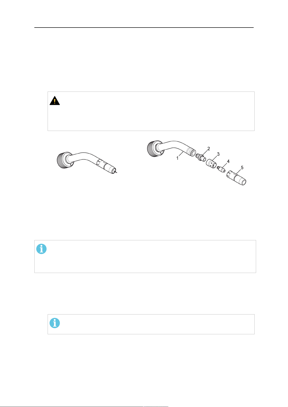
5.5.1 Torch neck equipment
The torch neck, see (1) in the illustration below, must always be equipped to suit the wire
diameter and material.
0463 373 101
- 47 -
© ESAB AB 2018
5 INSTALLATION
1. Select the correct wire guide, contact tip (4), tip holder (2), gas nozzle (5), and gas
diffuser/spatter protection (3). You will find an exact overview and possible alternative
equipment elements for various torch models in the spare parts list. Only use original
ESAB parts; only then is the fitting accuracy ensured.
2. Firmly tighten the tip holder and the contact tip using a suitable tool for example the
enclosed monkey wrench.
3. When using a split wire guide, remove the installed guide nipple including the o-ring
from the torch flange upon delivery if necessary (see section "Installing the neck
liner").
VARO!
The torch must be completely equipped before welding, especially the gas
diffuser and/or spatter protection and all necessary insulators have to be
installed according to the spare parts list. Welding without these items may
cause immediate destruction of the torch.
1 - Torch neck 4 - Contact tip
2 - Tip holder 5 - Contact tip
3 - Gas diffuser
5.5.2 Aristo RT torch neck installation
HUOM!
Check the O-rings on the flange of the torch neck before mounting. Replace the
O-rings if damaged or lost. Missing or faulty O-rings will lead to leaks of shielding
gas and coolant.
1. For hollow wrist systems, insert the torch into the torch mount in the correct
orientation, so that the locator pin fits into the slot of the RTKSC-2 or RTFLC-2
interface, see (A) in the illustration below. For standard systems, attach the torch to
the RT flange of the cable assembly, (B) in the illustration below.
Installation is only possible in the correct orientation.
2. Tighten the locking nut of the torch neck.
HUOM!
Only tighten by hand, never use tools or excessive force.
0463 373 101
- 48 -
© ESAB AB 2018

5 INSTALLATION
3. The correct seating of the torch can be checked by means of the window (1). If the
torch has been correctly mounted, no gap should be seen through the window (1).
5.6 Installing the wire guide for standard and hollow Wrist arm
Installing the wire guide
Choose the wire guide or liner depending on the filler wire material and diameter to be used,
see the spare parts list. Accurate performance of the system can only be guaranteed when
using original ESAB wire guides.
The recommended wire guide is the split wire guide, which consists of the neck liner and a
separate guide in the cable assembly. The front part of the wire guide, which is most
stressed, can be exchanged easily and independently of the cable assembly wire guide.
For correct installation, the following steps must be followed (example for Euro central
connector).
5.6.1 Installing the neck liner
The neck liner must be selected to fit the material and diameter of the welding wire, see the
spare parts list.
0463 373 101
- 49 -
© ESAB AB 2018

5 INSTALLATION
1. If present, remove the central guide nipple (1), from the torch neck using a hexagon
wrench (size 6 mm) or a large flat-blade screwdriver.
HUOM!
The guide nipple (1) can only be used with one-piece liners and must not be
used with the standard RT or hollow wrist system.
2. When replacing the neck liner:
Unfasten the sleeve nut and remove the torch neck.
Unfasten the liner nipple using a hexagon wrench (size 6 mm) and remove nipple and
liner from the torch neck.
3. Remove the gas nozzle and the contact tip.
4. Insert the new neck liner (2) into the torch. Carefully tighten the guide nipple using a
suitable tool, e.g. a hex-wrench (size 6 mm) or a large flat-blade screwdriver.
5. Cut the neck liner flush with the tip holder and remove the neck liner from the torch.
6. Install the contact tip.
7. Insert the neck liner again. It will be stopped by the contact tip. Measure the excess
liner sticking out of the neck.
8. Remove the liner again and shorten the front end by the measured length. Carefully
deburr the edge and make sure that the inner hole is not blocked.
9. Reinstall the neck liner and tighten the guide nipple in the neck.
5.6.2 Installing a split wire guide in the cable assembly
The correct liner must be inserted to suit the filler material and the wire diameter, see the
spare parts list.
The wire guide is inserted through the cable assembly from the rear, reaching the guide
nipple that is installed in the flange where the torch neck will be attached. The following
worksteps must be followed in order to correctly determine the wire guide length. (Example
for Euro central connector).
0463 373 101
- 50 -
© ESAB AB 2018

5 INSTALLATION
1. For standard RT system: Install the guide nipple (1) in the center hole of the neck
support flange, see illustration A below.
For hollow wrist system: Install the guide nipple (1) into the torch interface of the
RTKSC-2 / RTFLC-2 cover, see illustration B below.
2. Remove the sleeve nut (2) from the central connector, and remove the old wire guide.
3. Insert the wire guide through the central connection and push forwards as far as it will
go into the guide nipple (1), applying light pressure.
VARO!
Ensure that the wire guide has advanced right up to the stop at the front,
rotating and pushing forward gently.
4. Measure the excess length that needs to be cut from the wire guide.
5. Remove the wire guide again and shorten the front end by the measured length.
Steel liner: grind down the burred edges if needed.
Plastic liner: make a clean cut and chamfer the edges (e.g. with a pencil sharpener)
HUOM!
Make sure the inner opening of the liner is not obstructed by the cut wire end.
0463 373 101
- 51 -
© ESAB AB 2018

5 INSTALLATION
6. Reinstall the wire guide and attach the sleeve nut (2).
HUOM!
For hollow wrist systems where Infiniturn and Helix cable assemblies are
used, wire guides should be installed without tension so that the ends of the
liners may rotate freely.
Important note when using a plastic liner:
The wire channel between the drive rolls of the feeder and the central
connector of the torch must be fitted with a plastic liner. Depending on the
design of the feeder, a piece of plastic liner inserted into a brass guide tube
can be used.
During wire run-in, make sure that the wire is fed correctly into the plastic liner
of the torch. If necessary, remove the cable assembly from the feeder and
insert the wire, then reattach.
5.6.3 Installing a continuous wire guide in the cable assembly
Installing a steel liner
The wire guide is inserted through the cable assembly from the rear and reaches to the
contact tip. The following worksteps must be followed for the correct calculation of the length
(example for Euro central connector):
1. Install the torch (see section "Torch neck equipment").
2. Remove the gas nozzle and contact tip from the torch.
3. Remove the sleeve nut (D) from the Euro connector.
4. Push in the liner through the central connector and fix with the sleeve nut.
5. Cut off the liner flush with the nozzle holder. To determine the thread projection of the
contact tip, pull the liner backwards and screw in the contact tip.
6. Push the liner forwards as far as it will go to the contact tip applying light pressure on
the liner and measure the length to be shortened at the rear.
7. Now remove the liner again and cut the excess length measured off it’s front end. If
needed, grind down the burred edges. Make sure the inner opening of the liner is not
obstructed by the cut wire end.
8. The insulation of the liner must be removed after cutting off in the front area, such that
the insulation protrudes out of the RM2 flange by approx. 5 cm. For this, briefly
remove the torch neck.
9. Push the liner back in again and fix with the sleeve nut (D), see above. Re-install the
gas nozzle.
0463 373 101
- 52 -
© ESAB AB 2018

5 INSTALLATION
Installing a plastic liner
1. Mount the torch neck (see section "Torch neck equipment") and equip it with a gas
nozzle and contact tip.
2. Remove the sleeve nut (D) from the Euro connector.
3. Cleanly cut off the liner, slightly break the outer edges, point slightly (e.g. with a pencil
sharpener).
4. Insert the liner through the central connector into the cable assembly with fitted torch.
If it gets stuck, rotate the liner to free it and facilitate installation.
HUOM!
Make sure the liner is completely inserted by rotating it and slightly pushing it
forward, until you can feel it has reached its stop.
5. Mount the nipple (B) and the O-Ring (C), move it to the right position and fix it with the
sleeve nut (D) of the Euro central connector.
6. Measure the required overlap needed inside the wire feeder cabinet and cut the liner
accordingly.
5.7 Adjust the narrow gap contact tip
The adjusting tool RT42-NG is designed for the narrow gap torch necks RT42W-NG,
RT42G-NG and RT 82W-0°NG, torches with curved narrow gap contact tip. It facilitates the
precisely repeatable and fast changing of the curved contact tip.
HUOM!
The adjusting tool must be securely fastened to a stable base, in order to prevent
the position of the device in relation to the robot cannot change unintentionally. If the
exact orientation of the device is lost, the alignment of the contact tip used for the
elaboration of the welding programs can no longer be reproduced with precision.
Select a position within the operating range of the robot for orientation (alignment) of the
contact tip to the torch. Fasten the adjusting tool firmly to a base using the fastening grooves
provided for this purpose. Fastening material is not included with the adjusting tool. Select
fastening material (screws) to suit the existing conditions.
Save all motion sequences and stop positions required to change or align the wearing parts
to a separate robot program.
Before programming the welding tasks: plan at which orientation the contact tip is to stand in
relation to the torch. The torch must then be positioned in the desired rotational position and
the contact tip aligned using the adjusting device. Only then may the welding task be
programmed. If different orientations of the contact tip are required for various welding tasks,
the contact tip has to be aligned to the new position when the welding task is changed.
VAROITUS!
The gas nozzle and the torch head become very hot during welding. Always allow
the torch to cool down before replacing wearing parts or adjusting the contact tip.
0463 373 101
- 53 -
© ESAB AB 2018
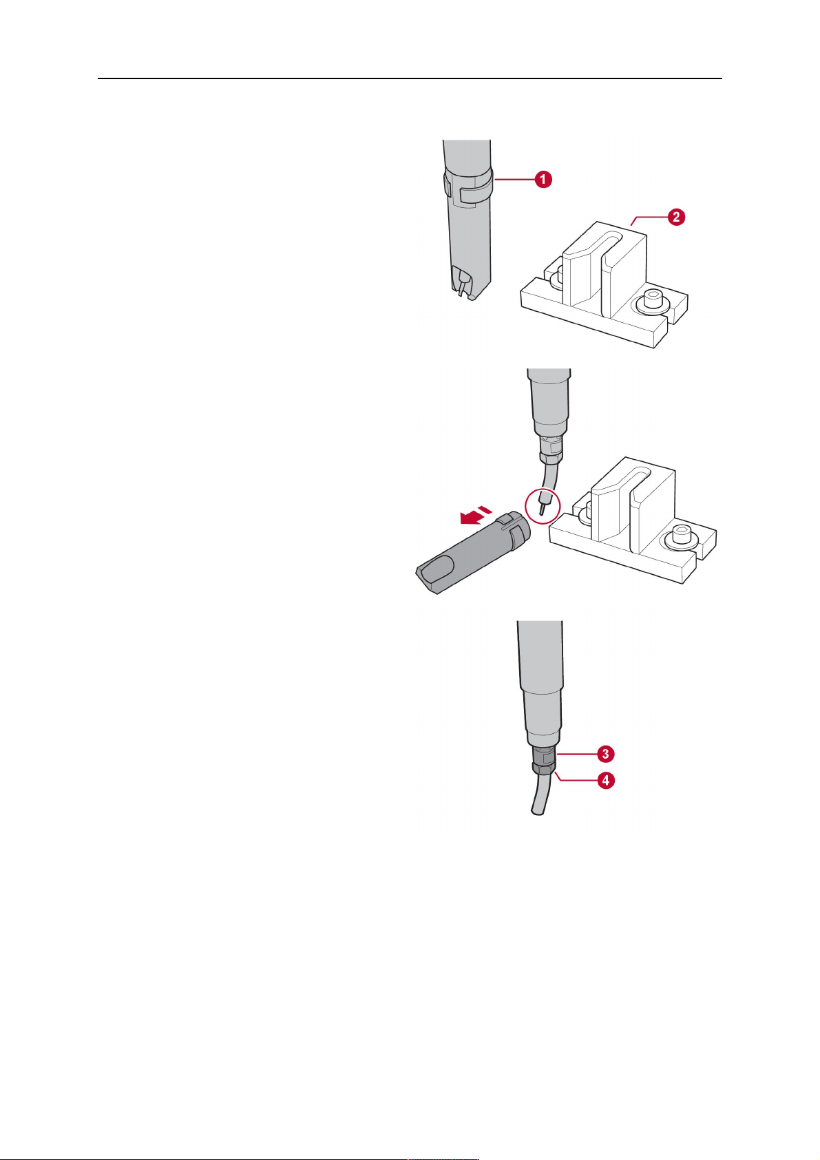
5 INSTALLATION
Adjust the contact tip
Move the robot torch to a position parallel to
the opening of the adjusting tool (2). Maintain
a sufficient distance to the work table to be
able to comfortably remove the gas nozzle.
Define this position in your robot program as
the wearing parts change position (stop
position 1).
Remove the gas nozzle by pulling it
downwards. Remove the welding wire in the
contact tip if necessary.
Loosen the counter nut (4) of the contact tip
while counter-holding the nozzle holder at the
wrench flat (3).
Unscrew the contact tip including the counter
nut from the nozzle holder and replace the
nozzle holder if necessary.
Completely screw the counter nut (4) onto the
new contact tip. Screw the contact tip
including the counter nut into the nozzle
holder.
Align the contact tip until it is parallel to the
opening of the adjusting tool. If necessary,
slightly unscrew the contact tip so that it can
be easily turned in both directions.
0463 373 101
- 54 -
© ESAB AB 2018

5 INSTALLATION
HUOM!
The contact tip must be able to be
easily moved by hand in both
directions in order to enable the
threading of the adjusting tool.
Place the robot torch or contact tip directly in
front of the opening of the adjusting tool (2)
(stop position 2).
Insert it slowly from the front until it is
completely inserted into the device (stop
position 3).
The contact tip was aligned exactly in the
device during insertion. Now cautiously
tighten the counter nut (4) in this position,
while counter holding the nozzle holder at the
wrench flat.
Slowly move the robot torch out of the
adjusting gauge, return to stop position 1 and
push on the gas nozzle as far as it will go.
Allow the welding wire to run into the contact
tip and bring the robot arm into welding
position.
0463 373 101
- 55 -
© ESAB AB 2018

6 OPERATION
6 OPERATION
VARO!
Before starting the system, check the whole installation according to the
manufacturer's instructions and applicable safety regulations.
Check the following to make sure that the system has been installed correctly:
1. Are all parts securely attached (torch, torch mount, flanges, safety-off device, cable
assembly, and wire feeder cabinet)?
2. Are all media hoses connected correctly and protected from damage?
3. Is the EURO central connector or direct connector fastened tightly?
4. Is the cable assembly length correct and suitable for the installation and can the cable
rotate freely? The cable must not be bent sharply. Any risk of the cable getting caught
on another object must be eliminated.
5. Is the control cable of the safety-off circuit connected and functioning? Move torch by
hand to test (RTKSC-2 and RTKS-2 only).
6. Is the torch firmly attached and is it completely equipped?
7. Is the wire guide installed according to the manual?
8. Are all lines and tubes arranged so that they cannot be damaged or bent?
The wire run-in can now be started, either via the wire run-in pushbutton or via the wire run-in
at the feeder.
6.1 Important information for programming (hollow wrist system only)
Fast rotation of axis 6 of the robot will significantly stress the cable assembly. In certain
cases, this can lead to damage or destruction of the cable. In order to maximize the lifetime
of the cable, we strongly suggest respecting the following limitations when programming the
robot.
Position of axis 5 Max. rotational speed of axis 6
0 – 60° 100 % (no limitations)
60° – 80° 300°/sec (approximately 50 % of max. robot speed)
> 80° 120°/sec (approximately 20 % of max. robot speed)
HUOM!
The above values are only indications. For information on the exact rotational speed
limits, refer to the individual robot manual or contact the robot supplier.
To reposition the torch quickly, the robot arm may have to be slightly extended first to achieve
a bending angle of max. 60° of axis 5. In this position, the maximum available rotation speed
of axis 6 can be used.
When using the ESAB Helix cable assembly, the max. rotation of ±270° from the neutral
position must not be exceeded.
0463 373 101
- 56 -
© ESAB AB 2018

6 OPERATION
VARO!
While axis 5 is bent more than 60°, the rotational speed of the torch around axis 6
must be limited, see table above.
Otherwise, the cable assembly may be damaged.
0463 373 101
- 57 -
© ESAB AB 2018

7 HUOLTO JA KUNNOSSAPITO
7 HUOLTO JA KUNNOSSAPITO
VAROITUS!
Ennen järjestelmän huolto- tai kunnossapitotöiden aloittamista laitteiston päävirta on
katkaistava. Noudata tämän käyttöoppaan alussa kerrottuja turvallisuusohjeita.
Vaurioituneita polttimia tai kaapelikokoonpanoja ei saa käyttää! Tunnetut viat on
annettava pätevän henkilöstön korjattavaksi ennen laitteiston seuraavaa
käyttökertaa.
VAROITUS!
Palovammojen vaara! Kaasusuutin ja polttimen pää kuumenevat voimakkaasti
hitsauksen aikana. Anna polttimen jäähtyä ennen huolto- ja kunnossapitotöiden
aloittamista.
VAROITUS!
Ehkäise henkilövahingot ja asennuksen vauriot noudattamalla seuraavia ohjeita:
1. RT KSC-2- tai RT FLC-2 -polttimen pidikkeen, RT KS-2 -turvamekanismin,
kaapelikokoonpanon tai Infiniturn-vesi- ja kaasuliitännän saa korjata vain
ESAB-huoltotuki.
2. Infiniturn-vesi- ja kaasuliitäntää ei saa koskaan avata. Se ei sisällä
käyttäjän huollettavissa olevia osia, ja se tuhoutuu purettaessa.
3. Älä koskaan pura RT KSC-2- tai RT KS-2 -yksikköä. Tämä on
jousikuormitteinen mekanismi. Virheellinen käsittely voi aiheuttaa vakavia
vammoja.
7.1 Pakolliset tarkistukset ja toimet
Ennen jokaista käyttökertaa:
• Tarkista, ovatko poltin, kosketuskärki, kaasusuutin, kaulan langanjohdin, kaapelit ja
kaikki varusteet kunnossa.
HUOM!
Jotta seisonta-aika olisi mahdollisimman lyhyt, on suositeltavaa vaihdella kahden
polttimen kaulan välillä, jolloin polttimen kaula on aina käyttövalmiina.
8 käyttötunnin välein (käyttökohteen mukaan):
• Vaihda kosketuskärki.
Päivittäin:
• Tarkista turvamekanismin toiminta käsin.
• Tarkista vauriot silmämääräisesti – esimerkiksi taipumat tai halkeamat.
• Tarkista langansyöttölaitteen oikea asento. Kaapelikokoonpano ei saa olla liian kireällä
tai löystynyt.
• Tarkista vesi- ja kaasuliitännät ja Infiniturn-vesi- ja kaasuliitäntä vuotojen varalta.
• Puhdista ja huolla poltin käyttöoppaan ohjeiden mukaisesti.
40 käyttötunnin välein (käyttökohteen mukaan):
• Vaihda langanjohtimet.
• Vaihda kaulan langanjohtimet.
Viikoittain tai tarpeen mukaan:
0463 373 101
- 58 -
© ESAB AB 2018

7 HUOLTO JA KUNNOSSAPITO
• Irrota langanohjain ja tarkista kuluminen ja likakertymät. Vaihda tarvittaessa.
Kuukausittain tai useammin vaativissa olosuhteissa (yli 8 tuntia päivässä):
• Puhalla langanohjain puhtaaksi paineilmalla (irrota kosketuskärki ja langanohjain).
• Varmista, että kaikki ruuvit on kiristetty.
• Tarkasta kaikkien liitosten ja letkujen eheys.
• Vaihda aina 250 kg:n hitsauslangan jälkeen.
Koulutetun henkilökunnan on korjattava sähköeristyksen vauriot, ennen kuin järjestelmää
voidaan käyttää turvallisesti.
0463 373 101
- 59 -
© ESAB AB 2018

8 VIANMÄÄRITYS
8 VIANMÄÄRITYS
Vika Mahdollinen syy Toimenpide
Lankaa ei voi
syöttää
Hitsauslankaa ei ole suoristettu
ennen sen syöttämistä
kaapelikokoonpanoon
Poltin ja kaapelikokoonpano ei ole
varustettu oikein langan halkaisijan
ja materiaalin mukaan
Langanohjainta ei ole asetettu
oikein kaapelikokoonpanoon
Kosketuskärki on tukkeutunut
langan jäämistä
Langanohjain on kulunut
Polttimen lika ja roskat haittaavat
langansyöttöä
Vedä tarvittaessa hitsauslanka
uudelleen ulos, leikkaa ja siisti
langan pää ja suorista 10 cm:n
pituinen osa langan alkupäästä.
Kierrä lanka tämän jälkeen takaisin
kaapelikokoonpanoon.
Tarkista langanohjain (polttimen
kaulan ja kaapelikokoonpanon) ja
kosketuskärki.
Vedä langanohjainta hieman ulos
Euro-liittimestä. Kun työnnät
langanohjainta, tunnet sen
viimeisten senttimetrien työntyvän
polttimen liitännän ohjausnippaan.
Jos näin ei tapahdu, langanohjain
on ehkä liian lyhyt eikä ole täysin
paikallaan.
Vaihda kosketuskärki ja/tai
langanohjain, puhalla polttimen
kaula, langanohjaimen putki ja
langanohjain puhtaaksi paineilmalla.
Poltin
kuumenee liikaa
Langansyötöss
ä on ongelmia
Kosketuskärkeä tai kärjen pidintä ei
Kiristä ne käsin sopivalla työkalulla.
ole kiristetty kunnolla
Jäähdytysjärjestelmä ei toimi oikein Tarkista jäähdytysveden virtaus,
määrä ja puhtaus.
Jäähdytysjärjestelmä ei ole oikein
kytketty
Tarkista liitännät (veden syöttö ja
paluu)
Poltin on ylikuormitettu Tarkista tekniset tiedot ja vaihda
tarvittaessa toisentyyppinen poltin.
Kaapelikokoonpano on viallinen Tarkista kaapelit, letkut ja liitännät.
Kosketuskärki on kulunut Vaihda kosketuskärki.
Langanohjain on kulunut/likainen Tarkista langanjohdin, puhalla
puhtaaksi. Vaihda tarvittaessa.
Asennetut kulutustarvikkeet eivät
Tarkista varaosaluettelo.
sovi langan halkaisijaan tai
materiaaliin
Langansyöttölaite ei ole oikein
säädetty
Kaapelikokoonpano on taittunut tai
taivutettu liian tiukalle mutkalle
Tarkista langansyöttörullat,
kosketuspaine ja kelajarru.
Tarkista, ettei
kaapelikokoonpanossa ole
vaurioita. Asettuuko langanjohdin
paikalleen helposti? Asenna
ohjeiden mukaisesti. Katso kohta
Kaapelikokoonpanon asennus.
0463 373 101
Lanka on likaantunut Käytä puhdistusvillaa.
- 60 -
© ESAB AB 2018

8 VIANMÄÄRITYS
Vika Mahdollinen syy Toimenpide
Langansyöttö
pysähtelee
hitsauksen
aikana.
Hitsausprosessi
pysähtelee.
Sauma on
huokoinen.
Lankakela on tyhjä Tarkista langan määrä
langansyöttölaitteen kelassa.
Kaapelikokoonpanossa on tukos Tarkista langan syöttö (mahdollisesti
liian nopea), tarkista, onko
kosketuskärjessä
epäpuhtauksia/tukkeumia, puhdista
tai vaihda kosketuskärki
tarvittaessa.
Lanka palaa kiinni kosketuskärkeen
Vaihda kosketuskärki.
tai kosketuskärki on kulunut
Turvakatkaisumekanismi on
lauennut.
Selvitä kosketuksen aiheuttajat ja
poista ne. Tarkista ohjausjohdon
liitännät.
Roiskeiden aiheuttama kaasupyörre Puhdista polttimen pää, käytä
kaasunhajotinta / roiskesuojaa.
Polttimen kaasuvirtaus on liian
heikko tai aivan liian voimakas
Tarkista virtausnopeus
mittaustyökalulla.
Kaasunsyötössä on vika Tarkista virtausnopeus ja
mahdolliset vuodot.
Langassa tai työkappaleessa on
kosteutta tai epäpuhtauksia
Tarkista lanka ja työkappale, käytä
vähemmän nestettä tai erilaista
roiskeenestonestettä.
Valokaari ei ole
vakaa.
Kosketuskärki on kulunut Vaihda kosketuskärki.
Hitsausparametrit ovat väärät Tarkista hitsauslaitteen asetukset.
Piirin sähköliitännät ovat
riittämättömät
Tarkista, että kaikki virtalähteen,
polttimen ja työkappaleen
sähköliitännät (myös
maadoituskaapeli) on kytketty
kunnolla.
0463 373 101
- 61 -
© ESAB AB 2018

9 VARAOSIEN TILAAMINEN
9 VARAOSIEN TILAAMINEN
VARO!
Laitteen korjaukset ja sähkötyöt saa suorittaa vain valtuutettu ESAB-huoltoteknikko.
Käytä ainoastaan alkuperäisiä ESAB varaosia ja kulutusosia.
ESAB RT -polttimet RT KS-2, RT FL-2, RT-KSC-2, RT-FLC-2, RT 42, RT 52, RT 62, RT 72,
RT 82, RT 42-NG ja RT 82W NG on suunniteltu ja testattu kansainvälisten ja
eurooppalaisten standardien IEC/EN 60974-7 mukaisesti. Huolto- tai korjaustyön suorittanut
yksikkö on velvollinen varmistamaan, että tuote täyttää edelleen kyseisen standardin
vaatimukset.
Vara- ja kulutusosia voi tilata lähimmän ESAB-jälleenmyyjän kautta. Siirry osoitteeseen
esab.com. Ilmoita tilatessasi varaosaluettelon mukainen tuotetyyppi, valmistenumero, nimike
ja varaosanumero. Tämä helpottaa lähetystä ja varmistaa oikean toimituksen.
0463 373 101
- 62 -
© ESAB AB 2018

9 VARAOSIEN TILAAMINEN
0463 373 101
- 63 -
© ESAB AB 2018

ESAB AB, Lindholmsallén 9, Box 8004, 402 77 Gothenburg, Sweden, Phone +46 (0) 31 50 90 00
http://manuals.esab.com
For contact information visit esab.com
 Loading...