


RT Robo Welding Torch System
RTKS-2, RTFL-2, KSC-2, FLC-2, RT42, RT52,
RT62, RT72, RT82, RT42-NG, RT82WNG
Instruction manual
0463 373 101 US 20181227


TABLE OF CONTENTS
1
SAFETY ....................................................................................................... 5
1.1 Meaning of symbols ............................................................................... 5
1.2 Safety precautions ................................................................................. 5
2
WARRANTY................................................................................................. 8
2.1 Conditions of intended use ................................................................... 8
3
INTRODUCTION.......................................................................................... 9
3.1 Overview of welding torch systems ..................................................... 9
4
TECHNICAL DATA ...................................................................................... 11
4.1 Welding torch neck ................................................................................ 11
4.2 Voltage rating.......................................................................................... 12
4.2.1 Cooling circuit limits.............................................................................. 12
4.3 Torch mount............................................................................................ 13
4.3.1 Torch mounts for standard RT system.................................................. 13
4.3.1.1 RTKS-2 safety-off mechanism.......................................................... 14
4.3.1.2 RTFL-2 intermediate flange .............................................................. 14
4.3.2 Torch mounts for hollow wrist system................................................... 14
4.3.2.1 RTKSC-2 G/W torch mount with safety-off mechanism ................... 16
4.3.2.2 RTFLC-2 G/W rigid torch mount ....................................................... 17
4.4 adapter flanges....................................................................................... 18
4.5 Cable assemblies ................................................................................... 18
4.5.1 Cable assemblies for standard RT system........................................... 18
4.5.2 Cable assemblies for hollow wrist systems .......................................... 19
5
INSTALLATION............................................................................................ 21
5.1 RTKS-2 standard arm installation........................................................ 21
5.1.1 RTKS-2 safety-off mechanism............................................................. 21
5.1.1.1 Torch installation with adjustable mount............................................ 22
5.1.2 Standard arm cable assembly for KS-2 and FL-2 ................................ 24
5.1.3 RTKS-2 wire feeder connection........................................................... 25
5.1.4 RTKS-2 electrical connections ............................................................ 26
5.1.4.1 RTKS-2 safety-off mechanism connection ....................................... 26
5.1.5 RTKS-2 Torch installation .................................................................... 27
5.2 RTFL-2 standard arm installation ........................................................ 28
5.2.1 RTFL-2 rigid mount.............................................................................. 28
5.2.2 RTFL-2 torch installation ..................................................................... 30
5.3 RTKSC-2 hollow wrist system installation.......................................... 30
5.3.1 RTKSC-2 mount with safety off mechanism ........................................ 30
5.3.2 Mounting the cable assembly ............................................................... 31
5.3.2.1 RTKSC-2 feeder cabinet connections .............................................. 32
5.3.3 RTKSC-2 cable assembly ................................................................... 34
5.3.3.1 RTKSC-2 cable assembly installation .............................................. 34
5.3.3.2 RTKSC-2 electrical connections ....................................................... 37
0463 373 101 © ESAB AB 2018

TABLE OF CONTENTS
5.3.4 RTKSC-2 torch installation .................................................................. 38
5.4 RTFLC-2 installation.............................................................................. 39
5.4.1 RTFLC-2 mount ................................................................................... 39
5.4.2 RTFLC-2 wire feeder connection......................................................... 39
5.4.2.1 Feeding through the robot arm .......................................................... 39
5.4.2.2 RTFLC-2 feeder cabinet connections ............................................... 40
5.4.3 RTFLC-2 cable assembly .................................................................... 42
5.4.3.1 RTFLC-2 cable assembly installation ............................................... 42
5.4.4 RTFLC-2 electrical connections .......................................................... 45
5.4.4.1 RTFLC-2 hollow wrist system with Infiniturn cable assembly........... 45
5.4.4.2 RTFLC-2 hollow wrist system with Helix cable assembly................. 46
5.5 Torch installation.................................................................................... 46
5.5.1 Torch neck equipment .......................................................................... 46
5.5.2 Aristo RT torch neck installation ........................................................... 47
5.6 Installing the wire guide for standard and hollow Wrist arm ............. 48
5.6.1 Installing the neck liner ......................................................................... 48
5.6.2 Installing a split wire guide in the cable assembly ................................ 49
5.6.3 Installing a continuous wire guide in the cable assembly ..................... 51
5.7 Adjust the narrow gap contact tip ........................................................ 52
6
OPERATION ................................................................................................ 55
6.1 Important information for programming (hollow wrist system only) 55
7
SERVICE AND MAINTENANCE ................................................................. 57
7.1 Mandatory checks and actions ............................................................. 57
8
TROUBLESHOOTING ................................................................................. 59
9
ORDERING SPARE PARTS ........................................................................ 61
Rights reserved to alter specifications without notice.
0463 373 101 © ESAB AB 2018

1 SAFETY
1 SAFETY
1.1 Meaning of symbols
As used throughout this manual: Means Attention! Be Alert!
DANGER!
Means immediate hazards which, if not avoided, will result in immediate,
serious personal injury or loss of life.
WARNING!
Means potential hazards which could result in personal injury or loss of life.
CAUTION!
Means hazards which could result in minor personal injury.
WARNING!
Before use, read and understand the instruction manual
and follow all labels, employer's safety practices and
Safety Data Sheets (SDSs).
1.2 Safety precautions
Users of ESAB equipment have the ultimate responsibility for ensuring that anyone who
works on or near the equipment observes all the relevant safety precautions. Safety
precautions must meet the requirements that apply to this type of equipment. The following
recommendations should be observed, in addition to the standard regulations that apply to
the workplace.
All work must be carried out by trained personnel well-acquainted with the operation of the
equipment. Incorrect operation of the equipment may lead to hazardous situations, which
could result in injury to the operator and damage to the equipment.
1. Anyone who uses the equipment must be familiar with:
○ its operation
○ the location of emergency stops
○ its function
○ the relevant safety precautions
○ welding and cutting or other applicable operation of the equipment
2. The operator must ensure that:
○ no unauthorized person is within the working area of the equipment when it is
started up
○ no-one is unprotected when the arc is struck or work is started with the
equipment
3. The workplace must:
○ be suitable for the purpose
○ be free from drafts
0463 373 101
- 5 -
© ESAB AB 2018

1 SAFETY
4. Personal safety equipment:
○ Always wear recommended personal safety equipment, such as safety glasses,
flame-proof clothing, safety gloves
○ Do not wear loose-fitting items, such as scarves, bracelets, rings, etc., which
could become trapped or cause burns
5. General precautions:
○ Make sure the return cable is connected securely
○ Work on high voltage equipment may only be carried out by a qualified
electrician
○ Appropriate fire extinguishing equipment must be clearly marked and close at
hand
○ Lubrication and maintenance must not be carried out on the equipment during
operation
WARNING!
Arc welding and cutting may cause injury to yourself and others. Take precautions
when welding and cutting.
ELECTRIC SHOCK - Can kill
• Install and ground the unit in accordance with instruction manual.
• Do not touch live electrical parts or electrodes with bare skin, wet gloves,
or wet clothing.
• Insulate yourself from work and ground.
• Ensure your working position is safe
ELECTRIC AND MAGNETIC FIELDS - Pose health risks
• Welders with pacemakers fitted should consult their doctor before welding.
EMF may interfere with some pacemakers.
• Exposure to EMF may have other health effects which are unknown.
• Welders should use the following procedures to minimize exposure to
EMF:
○ Route the electrode and work cables together on the same side of
your body. Secure them with tape when possible. Do not place your
body between the torch and work cables. Never coil the torch or work
cable around your body. Keep the welding power source and cables
as far away from your body as possible.
○ Connect the work cable to the workpiece as close as possible to the
area being welded.
FUMES AND GASES - Can be dangerous to your health
• Keep your head out of the fumes.
• Use ventilation, extraction at the arc, or both, to take fumes and gases
away from your breathing zone and the general area.
ARC RAYS - Can injure eyes and burn skin
• Protect your eyes and body. Use the correct welding screen and filter lens
and wear protective clothing.
• Protect bystanders with suitable screens or curtains.
0463 373 101
NOISE - Excessive noise can damage hearing
Protect your ears. Use ear defenders or other hearing protection.
- 6 -
© ESAB AB 2018

1 SAFETY
MOVING PARTS - Can cause injuries
• Keep all doors, panels and covers closed and securely in place. Have only
qualified people remove covers for maintenance and troubleshooting as
necessary. Reinstall panels or covers and close doors when service is
finished and before starting engine.
• Stop engine before installing or connecting unit.
• Keep hands, hair, loose clothing and tools away from moving parts.
FIRE HAZARD
• Sparks (spatter) can cause a fire. Make sure there are no inflammable
materials nearby.
• Do not use on closed containers.
MALFUNCTION - Call for expert assistance in the event of malfunction.
PROTECT YOURSELF AND OTHERS!
CAUTION!
This product is solely intended for arc welding.
WARNING!
Do not use the power source for thawing frozen pipes.
CAUTION!
Class A equipment is not intended for use in residential
locations where the electrical power is provided by the
public low-voltage supply system. There may be
potential difficulties in ensuring electromagnetic
compatibility of class A equipment in such locations,
due to conducted as well as radiated disturbances.
NOTE!
Dispose of electronic equipment at a recycling
facility!
To conform with the European Directive 2012/19/EC on
Waste Electrical and Electronic Equipment and its
implementation in accordance with national law,
electrical and/or electronic equipment that has reached
the end of its life must be disposed of at a recycling
facility.
As the person responsible for the equipment, it is your
responsibility to obtain information on approved
collection stations.
For further information contact the nearest ESAB dealer.
ESAB has an assortment of welding accessories and personal protection equipment
for purchase. For ordering information, contact your local ESAB dealer or visit us on
our website.
0463 373 101
- 7 -
© ESAB AB 2018

2 WARRANTY
2 WARRANTY
Before delivery, our products are carefully checked. ESAB verifies that each product is free
from defects of material and workmanship at the time of delivery and is functioning according
to its intended use.
ESAB provides warranty on defects of material and workmanship according to legal
requirements. Consumables are exempt from this warranty.
The warranty does not cover any damages or functional defects resulting from:
• overloading, abusing or diverting from intended use of the product
• collisions or accidents
• non-compliance with instructions stated in these operating instructions
• improper installation or assembly
• insufficient maintenance
• modifying the product from its original state
• chemical influences
• normal wear and tear
ESAB assumes no liability other than for replacement or repair of faulty parts.
2.1 Conditions of intended use
1. The product is intended for industrial and commercial use and must only be utilized by
trained personnel. The manufacturer is not liable for any damage or accidents
resulting from improper usage.
2. The Aristo® RT Robotic Welding System is designed and produced at the state of the
art and is safe and reliable in operation when handled, installed and maintained by
trained personnel. The instructions for installation, operation and maintenance
described in this document must be followed.
3. The Aristo® RT Robotic Welding System may only be installed, operated and serviced
by trained personnel. The installation, operation, and maintenance regulations
detailed in this manual are to be followed.
4. The Aristo® RT Robotic Welding System may solely be used for the purpose intended
by the manufacturer within the framework of its technical data and with automated
handling systems. The type of torch must be selected to suit the welding task.
5. The Aristo® RT Robotic Welding System was designed for use as a complete system.
The incorporation of components from other manufacturers into the system is not
permissible.
6. The RT KS-2 and RT KSC-2 are only to be used as emergency stop mechanisms
within their technical specifications and in combination with a RT standard arm cable
assembly (KS-2), Infiniturn or Helix (KSC-2), ESAB adapter flange, including RT torch
mounts (KS-2) and an Aristo RT welding torch.
7. No oil or anti-spatter fluid should be added to the blow-out gas. ESAB does not
guarantee chemical resistance to those substances. ESAB recommends using the
ESAB spraying unit to apply the minimum amount of anti-spatter fluid to the torch and
therefore protect the environment.
8. The product must be kept dry and protected from humidity when transported, stored or
used.
9. The system is designed for environmental temperatures ranging from 5 °C to 40 °C
(41 °F to 104 °F). In case these limits are exceeded, specific action is needed. In case
of frost risk, use a suitable coolant.
0463 373 101
- 8 -
© ESAB AB 2018

3 INTRODUCTION
3 INTRODUCTION
The RT welding torch systems are developed for fully automatic MIG/MAG welding using
robots. The systems consist of a variety of Aristo RT torch necks designed for robotic use,
torch mounts, cable assemblies optimized for robotic use, and safety-off features to prevent
the system from damage in case of collision.
The standard RT welding system provides collision protection through the use of RTKS-2
which is a mechanical spring-loaded safety-off functionality. This can optionally be replaced
by RTFL-2 to take advantage of the collision detection function of the robot control system.
The standard RT welding system can be used with a variety of cable assembly types.
RTKSC-2 and RTFLC-2 torch mounts with Infiniturn or Helix cable assemblies are intended
for use in hollow wrist robot welding systems designed for advanced welding applications.
The safety-off mechanism in the RTKSC-2 torch mount allows for large elastic deflection of
the torch in case of collision. The Infiniturn and Helix cable assemblies are simple to install,
providing a highly reliable system with precise maneuvering capabilities.
In combination with the well-established Aristo RT robot welding torches, these constituents
create a highly reliable and long-lasting system which needs only a minimum of
maintenance.
The instruction manual is included on delivery of torch mounts and cable assemblies.
The ESAB ordering numbers, available accessories, spare parts, and wear parts are
found in the spare parts list.
3.1 Overview of welding torch systems
Standard RT system
For a detailed description refer to the
corresponding section in the TECHNICAL
DATA chapter:
1. Torch neck
See "Welding torch".
2. Cable assembly
See "Cable assemblies for standard
RT system".
3. Torch mount
See "Torch mounts for standard RT
system".
4. RTKS-2 safety-off mechanism
See "RTKS-2 safety-off
mechanism".
5. RTFL-2 intermediate flange
See "RTFL-2 intermediate flange".
6. Adapter flange (if required)
See "Adapter flanges".
0463 373 101
- 9 -
© ESAB AB 2018

3 INTRODUCTION
Hollow wrist system
For a detailed description refer to the
corresponding section in the TECHNICAL
DATA chapter:
1. Torch neck
See "Welding torch".
2. Torch mount RTKSC-2
See "RTKSC-2 torch mount with
safety-off mechanism".
3. Torch mount RTFLC-2
See "RTFLC-2 rigid torch mount".
4. Adapter flange
See "Adapter flanges".
5. Cable assembly Helix or Infiniturn
See "Cable assemblies for hollow
wrist systems".
0463 373 101
- 10 -
© ESAB AB 2018

4 TECHNICAL DATA
4 TECHNICAL DATA
4.1 Welding torch neck
Choose your torch model according to the welding application. The required duty cycle and
capacity, the cooling method, and the wire diameter must be considered. If there are
increased requirements, for example caused by preheated work pieces or high heat
reflection in corners, take these into account by selecting a welding torch with adequate
reserve in its power rating.
RT welding torches are intended for the use with CE-conformant welding power sources for
the processes of Metal Inert Gas welding (MIG), Metal Active Gas welding (MAG) and MIG
Brazing with commercial round wires. Do not use the torch for other processes.
For pulsed arc welding of steel or aluminum welding, the RT82W water cooled torch must be
used.
See the available torch models below.
Torch model Cooling method Shielding gas Rating
RT42G Gas cooled CO
Gas cooled 300A / 100%
Gas cooled Mix 350A / 60%
Gas cooled 250A / 100%
RT42W Water cooled CO
Water cooled 420A / 100%
Water cooled Mix 350A / 60%
Water cooled 350A / 100%
RT52G Gas cooled CO
Gas cooled 300A / 100%
Gas cooled Mix 350A / 60%
Gas cooled 250A / 100%
RT52W Water cooled CO
Water cooled 470A / 100%
Water cooled Mix 400A / 60%
Water cooled 400A / 100%
RT62G Gas cooled CO
Gas cooled 340A / 100%
2
2
2
2
2
420A / 60%
420A / 60%
420A / 60%
470A / 60%
500A / 60%
Gas cooled Mix 420A / 60%
Gas cooled 290A / 100%
RT62W Water cooled CO
Water cooled 530A / 100%
Water cooled Mix 450A / 60%
Water cooled 450A / 100%
0463 373 101
- 11 -
2
530A / 60%
© ESAB AB 2018

4 TECHNICAL DATA
Torch model Cooling method Shielding gas Rating
RT72G Gas cooled CO
2
480A /60%
Gas cooled 320A / 100%
Gas cooled Mix 400A / 60%
Gas cooled 270A / 100%
RT72W Water cooled CO
2
480A / 60%
Water cooled 430A / 100%
Water cooled Mix 480A / 60%
Water cooled 430A / 100%
RT82W Water cooled CO
2
600A / 60%
Water cooled 600A / 100%
Water cooled Mix 550A / 60%
Water cooled 550A / 100%
The values for torch rating and duty cycle are valid for a ten-minute cycle.
The technical data is valid for a standardized application utilizing the standard wear/spare
parts. The torch rating is reduced when using pulsed arc metal transfer mode.
Temperature ranges Storage: -15–50°C (5–122°F)
Operation: 5–40°C (41–104°F)
Blow-out gas Max. 10 bar, separate gas hose
Total weight (torch neck, safety-off
Approximately 5 kg
mechanism, torch mount and 1-m cable
assembly)
4.2 Voltage rating
Max. permitted voltage / amperage
Complete welding torch system 141 V (peak value for welding)
RTKS-2 safety-off control circuit
RTKS-2 push-button
RT KSC-2 safety off control circuit 48 V
Using nozzle sense functionality with a
standard cable assembly
Using nozzle sense functionality with Helix or
Infiniturn cable assemblies
24 V / 1 A
48 V / 0.1 A
50 V / 5 A
(Allowed load max. 1 minute at the rated
nominal current)
50 V / 5 A
(Allowed load max. 1 minute at the rated
nominal current)
The indicated ratings refer to a standardized case of use.
For cable assembly ratings, see the section "Cable assemblies".
4.2.1 Cooling circuit limits
Valid for water cooled version only.
0463 373 101
- 12 -
© ESAB AB 2018

4 TECHNICAL DATA
Min. water flow rate: 1.0 l/min (1.1 quarts/min)
Min. water pressure: 2.5 bar (36.3 PSI)
Max. water pressure: 3.5 bar (50.8 PSI)
Inlet temperature: Max. 40 °C (104 °F)
Return temperature: Max. 60 °C (140 °F)
Cooling capacity: Min. 1000 W, depending on application
CAUTION!
Return temperatures above 60 °C (140 °F) may cause damage or destroy the cable
assembly.
4.3 Torch mount
The type of torch mount required depends on the RT welding torch system design and on the
choice of safety-off devices. See the section "Overview welding torch systems".
Component Approximate weight
Torch mount (for standard system) 1102.3lb (0.43 kg)
RTKS-2 safety-off mechanism (for standard
1102.3lb (0.85 kg)
system)
RTFL-2 intermediate flange (for standard
1102.3lb (0.35 kg)
system)
RTKSC-2 torch mount (for hollow wrist
1102.3lb (1.90 kg)
system)
RTFLC-2 rigid torch mount (for hollow wrist
1102.3lb (1.22 kg)
system)
Robot welding torch 1102.3lb (0.66 kg)
4.3.1 Torch mounts for standard RT system
For standard RT systems the torch mount is installed on the RTKS-2 safety-off mechanism
(alternatively on the RTFL-2 intermediate flange), clamping the cable assembly and the
connected torch neck.
Select the torch mount in accordance with the type of torch and its geometry. Various mount
types may be used. See the spare parts list for available torch mounts for standard RT
system.
Torch mount for standard arm robots
0463 373 101
- 13 -
© ESAB AB 2018

4 TECHNICAL DATA
4.3.1.1 RTKS-2 safety-off mechanism
The RTKS-2 safety mechanism is a spring supported device that protects the robot and the
torch system in case of a collision.
NOTE!
Do not disassemble the RTKS-2.
4.3.1.2 RTFL-2 intermediate flange
The rigid intermediate flange RTFL-2 can be used instead of the RTKS-2 if the robot has
an electronic collision detection system.
4.3.2 Torch mounts for hollow wrist system
In the hollow wrist system the Aristo RT welding torch necks are connected to the torch
mount KSC-2 or FLC-2.
The torch mount RTKSC-2 allows for elastic deflection of the torch in case of a collision. At
the same time, an electrical contact is opened, signaling the robot control to stop. After
resetting the error, the initial geometry and Tool Center Point (TCP) of the torch will be
reached with high precision. The system functions purely mechanically and is spring loaded.
The torch mount RTFLC-2 has no built-in safety-off function.
0463 373 101
- 14 -
© ESAB AB 2018

4 TECHNICAL DATA
For hollow wrist systems RTKSC-2 G/W (alternatively RTFLC-2 G/W) is recommended.
This torch mount can be used with both gas-cooled and water-cooled torches in the Aristo
RT series.
RTKSC-2 G/W RTFLC-2 G/W
Functional principle of the
Mechanical Not applicable (rigid mount)
safety-off mechanism
Axial release force (Fz) 650 N Not applicable (rigid mount)
Release torque on transverse
669lb-ft (24 Nm) Not applicable (rigid mount)
axis (Mx)
Reset after release Automatic Not applicable (rigid mount)
Repeatability Lateral ± 0.1 mm at the TCP
Not applicable (rigid mount)
of a standard Aristo RT torch
Max. deflection Approx. ± 8° Not applicable (rigid mount)
Safety switch Normally closed
Not applicable (rigid mount)
Electrical load max. 48 V / 1A
0463 373 101
- 15 -
© ESAB AB 2018

4 TECHNICAL DATA
Electrical control circuit for
nozzle sense function
Rating:
• For Helix cable
assemblies: max. 50 V
DC / 5 A, max. 1 minute
After detection of
contact, quickly
disconnect the sensing
voltage.
• For Infiniturn cable
assemblies, the nozzle
Rating:
• For Helix cable
assemblies: max. 50 V
DC / 5 A, max. 1 minute
• For Infiniturn cable
assemblies: max. 50 V
DC / 1 A, max. 1 minute
After detection of contact,
quickly disconnect the
sensing voltage.
sense function has
limited functionality.
Contact ESAB for a
detailed investigation of
possible solutions in
your application.
Voltage rating Maximum permitted voltage
for the safety off control
circuit: 48 V.
4.3.2.1 RTKSC-2 G/W torch mount with safety-off mechanism
Item Description Function
1 Torch neck support Aristo RT torch interface
2 RTKSC-2 cover Assembly with cable and torch interfaces
58.3/3Rubber boot Protection for safety-off mechanism
0463 373 101
- 16 -
© ESAB AB 2018

4 TECHNICAL DATA
Item Description Function
58.3/4RTKSC-2 main body Allows for mechanical deflection during a collision
58.3/5Adapter flange Isolating interface to robot wrist (must fit the specific
robot)
58.3/6Index pin For precise alignment to the adapter flange
58.3/7Connector for control cable Electrical connection for collision signal and nozzle
sense function
58.3/8Micro switch Sensor for collision detection
4.3.2.2 RTFLC-2 G/W rigid torch mount
Item Description Function
1 Torch neck support Aristo RT torch interface
2 RTFLC-2 cover Assembly with cable and torch interfaces
58.3/3RTFLC-2 main body Allows for mechanical deflection during a collision
58.3/4Index pin For precise alignment to the adapter flange
58.3/5Adapter flange Isolating interface to robot wrist (must fit the specific
robot)
58.3/6Connector for control cable
(3-pole)
0463 373 101
Electrical connection for the nozzle sense function
(if applicable)
- 17 -
© ESAB AB 2018

4 TECHNICAL DATA
4.4 adapter flanges
Choose the adapter flange required for installation on the robot arm depending on the robot
type. Adapter flanges for all suitable standard and hollow wrist systems are available. See
the spare parts list.
4.5 Cable assemblies
The connection to the wire feeder is effected by the cable assembly, the available versions
mainly depending on system design and cooling media (gas or water). See the spare parts
list.
The ratings are valid for cable lengths from 1 to 5 m.
Standard cable
Infiniturn Helix
assembly
Rating (10 min. cycle)
Gas cooled (mixed
gas)
Rating (10 min. cycle)
Water cooled
Max. 500 A / 60 %
duty cycle
Max. 350 A / 100 %
duty cycle
Max. 600 A / 100 %
duty cycle
Max. 400 A / 60 %
duty cycle
Max. 320 A / 100 %
duty cycle
Max. 550 A / 100 %
duty cycle
Max. 400 A / 60 %
duty cycle
Max. 320 A / 100 %
duty cycle
Max. 550 A / 100 %
duty cycle
Rotational range Limited rotatability Endlessly rotatable ± 270° from neutral
position
Weight
Gas cooled
Weight
Water cooled
1.2 m long:
1102.3lb (2.35 kg)
1.2 m long:
1102.3lb (2.35 kg)
1.0 m long:
1102.3lb (2.0 kg)
1.0 m long:
1102.3lb (2.0 kg)
1.0 m long:
1102.3lb (2.0 kg)
1.0 m long:
1102.3lb (2.0 kg)
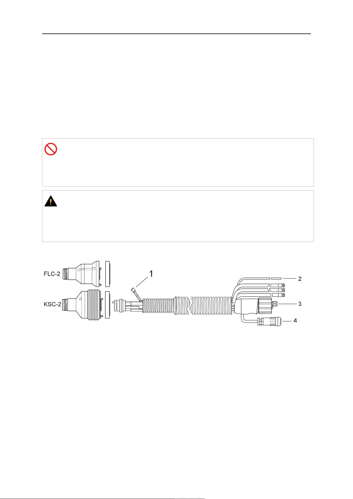
4.5.1 Cable assemblies for standard RT system
0463 373 101
- 18 -
© ESAB AB 2018

4 TECHNICAL DATA
Burndy connector pins
A. Touch sense Gas Nozzle
C. Collision sensor
D. Collision sensor
F. 0V
G. + Motor voltage
H. - Motor voltage
E. Inching
Item Description Function
1 Neck support flange Torch interface
2 Protective cover Protects cable assembly from damage
58.3/3Burndy connector, 12-pole Electrical connection between safety-off and wire
feeder
58.3/4Control cable For KS-2 (safety-off and push button)
58.3/5EURO connector Wire feeder connection
58.3/6Blow-out hose (black cap) For cleaning the torch with compressed air after
cleaning cycle
58.3/7Water inlet (blue cap)
Water inlet for torch cooling
1)
58.3/8Water return (red cap)
58.3/9Control cable plug for safety-off
mechanism
1)
Only water cooled torch systems
Water return of heated water from the torch
Electrical connection with RTKS-2 for the safety-off
signal and nozzle sense function
1)
4.5.2 Cable assemblies for hollow wrist systems
The Infiniturn cable assembly allows endless rotation of the torch in both directions. At the
same time, cooling fluid, shielding gas, blow-out air, welding power, and the signal of the
safety-off mechanism are transferred.
The Helix cable assembly is designed for a rotational range of ±270° from the neutral
position. It can be used for welding tasks that do not require endless rotation.
The Infiniturn cable assemblies are available in gas and water cooled versions. The Helix
cable assemblies can be universally used for gas or water cooled applications.
NOTE!
Do not connect a Helix cable assembly operated with a gas cooled torch neck to a
water cooling system.
0463 373 101
- 19 -
© ESAB AB 2018

4 TECHNICAL DATA
Item Description Function
1 Flange Torch mount RTKSC-2 / RTFLC-2 interface
2 Index pin Secures correct coupling orientation
58.3/3Control cable plug Electrical connection to RTKSC-2 for safety-off
signal and nozzle sense function (if applicable)
58.3/4EURO connector Wire feeder connection
58.3/5Control cable Electrical connection for the safety-off signal (from
RTKSC-2) and nozzle sense function (nozzle sense
is standard for Helix, not for Infiniturn)
58.3/6Water return (red cap) Water return of heated water from the torch
58.3/7Water inlet (blue cap) Water inlet for torch cooling
58.3/8Blow out hose (black cap) For cleaning the torch with compressed air after
welding
58.3/9Media coupling Endlessly rotatable coupling with media transfer
58.3/
Protective cover Protects cable assembly from damage
10
0463 373 101
- 20 -
© ESAB AB 2018

5 INSTALLATION
5 INSTALLATION
WARNING!
For your own safety, make sure that the robot is either in standby or power-less
state before doing maintenance work in the moving radius of the robot.
Follow the assembly instructions exactly. Pay attention during assembly that the cables are
not damaged. Damaged cables can lead to a short circuit, which may damage the electronics
of the robot or the welding torch.
Use only original ESAB components that have been specially developed for this purpose.
Only then the correct functioning of the whole welding torch system can be guaranteed.
5.1 RTKS-2 standard arm installation
5.1.1 RTKS-2 safety-off mechanism
1. Dismount the insulation flange (10) from the RTKS-2 (11) by removing the screws
(12).
2. Position the insulation flange (10) with the index pin on the robot arm and fix it with the
screws (20) included.
The insulation flange (10) is directly compatible with robots with tool flange according
to DIN ISO 9409-1-A40 (diameter 40mm, 4×M6). If the insulation flange (10) does
not fit, use an adapter flange (21).
NOTE!
Ensure that the index pin is located correctly. The maximum torque of 1.2Nm
(10.5in.lb) must be observed for the fastening of the adapter flange screws.
Prevent self-loosening of the screws by using suitable thread locking
measures.
3. Mount the RTKS-2 the back on the insulation flange (10).
0463 373 101
- 21 -
© ESAB AB 2018

5 INSTALLATION
4. Position the mount on the RTKS-2 and carefully insert the cylindrical pins (14) into the
holes provided. Take the position of the torch into account. Two mounting positions
may be potentially possible.
5. Screw the mount evenly using the enclosed cylinder screws with hexagon socket (12).
NOTE!
The maximum tightening torque for the cylinder screw (5) is 6Nm (53in.lb)
and the property class category is 8.8.
12 - Cylinder screw with hexagon socket
M6DIN912 (length of the screw depending
on the torch mount)
14 - Cylindrical pins Ø4×20
5.1.1.1 Torch installation with adjustable mount
Torch mounts with a central clamping assembly can only be fastened on the journal of the
mounting flange. For this, the mounting flange must be fastened first.
1. If applicable, carefully press the cylindrical pins (1) into the corresponding holes in the
mounting flange. The pins should protrude by approximately 5 mm (0.2 in.).
2. Position the mount on the safety-off mechanism RTKS-2 and carefully insert the
cylindrical pins (1) into the holes provided. In doing so, take the later position of the
torch into account. Two mounting positions may be potentially possible.
3. Then screw down the mounting flange evenly using the enclosed cylinder screws with
hexagon socket (2).
NOTE!
The maximum tightening torque for the cylinder screw (2) is 7.1 Nm (62.8
in.lb) and the property class category is 8.8.
0463 373 101
- 22 -
© ESAB AB 2018

5 INSTALLATION
4. Unscrew the axial cylinder screw with hexagon socket (4) out of the mounting flange
together with the washer (3).
1 - Cylindrical pins Ø4×14 3 - Washer Ø9 mm
2 - Cylinder screw with hexagon socket
M6×16
4 - Axial cylinder screw with hexagon
socket M8×16
5. Place the torch mount (5) onto the journal (6) of the mounting flange, paying attention
while doing so to the exact alignment of the feather key (7) and the corresponding
groove (7a).
6. Insert the clamping mandrel (8) into the lateral hole (see illustration) and position it so
that the mating surfaces (9a) of the clamping mandrel rest on the mating surface (9) of
the journal.
0463 373 101
- 23 -
© ESAB AB 2018

5 INSTALLATION
7. Fix the clamping mandrel from the opposite side using the M6 cylinder screw with
hexagon socket (10) and the Ø22 mm washer (11).
8. Screw the axial cylinder screw (4) with the Ø9 mm washer (3) into the mounting flange
and tighten firmly.
3 - Washer Ø9 mm 8 - Clamping mandrel
4 - Axial cylinder screw with hexagon
9 - Mating surface of mounting flange
socket M8×16
5 - Torch mount 9a - Mating surfaces of clamping mandrel
6 - Mounting flange journal 10 - Cylinder screw with hexagon socket
M6×30
7 Feather key 11 - Washer Ø22×6.4 mm
7a - Groove for feather key
5.1.2 Standard arm cable assembly for KS-2 and FL-2
The cable assembly must be aligned to the intended use in length and design. The type of
cooling for the torch and the cable assembly must be the same (either gas or water cooled
respectively). In order to prevent damage to the torch system and other components, it is
imperative to observe the following instructions.
0463 373 101
- 24 -
© ESAB AB 2018

5 INSTALLATION
CAUTION!
• Coordinate the length and design of the cable assembly to suit the range of
action of the robot.
• Do not bend, compress or overstretch the cable assembly.
• Fix the cable assembly such that is can be moved freely and cannot become
entangled.
• Any additional holding devices possibly installed, for example a balancer,
must not crush or bend the cable assembly.
• Extreme turning movements must be avoided in which the cable assembly
may become twisted.
• Chafing on the robot or other objects must be excluded.
1. Unscrew the cylinder screws (1) and lift off the top section (2) of the torch mount.
2. Insert the feather key (4) into the recess of the neck support flange (3) from below.
3. Align the neck support flange (3) including the feather key (4) to the groove (5) of the
torch mount and push into the groove right up to the stop of the flange.
4. Hold the cable assembly in this position and simultaneously place the top section (2)
back onto the torch mount. First screw both cylinder screws (1) loosely in to about the
same length, then tighten alternately. The top section (2) of the mount should have an
even gap to the bottom section.
The front part of the cable assembly is directly clamped into the torch mount (see
illustration below).
1 - Cylinder screws 4 - Feather key
2 - Torch mount top section 5 - Groove for feather key
3 - Neck support flange
5.1.3 RTKS-2 wire feeder connection
In order to be able to create the connection, the cable assembly must be mounted as
described in the "Installing the cable assembly" section and equipped following "Installing the
wire guide" section. Only then can the central and media connection take place. Proceed as
described below:
0463 373 101
- 25 -
© ESAB AB 2018

5 INSTALLATION
1. Connect the central connector of the cable assembly (2) to the wire feeder cabinet
socket. Tighten the central connector sleeve nut fingertight. Do not use tools.
1 - Burndy Connector 4 - Return of heated water (red cap)
2 - EURO central connector 5 - Return of heated water (red cap)
3 - Air blow-out 6 - Main Wire feeder
2. For water cooled systems. Connect the water hoses to the cooling circuit. The end of
the hose marked blue (4) is connected to the water outlet, and the end marked red (5)
is connected to the water return.
3. Connect the blow-out line (3) to the corresponding connection of the feeder.
4. Connect the Burndy Connector to the wire feeder. (1) to the feeder. See section
"Electrical connections".
NOTE!
All hoses and the control line must be installed so they can not bend or get
damaged!
5.1.4 RTKS-2 electrical connections
5.1.4.1 RTKS-2 safety-off mechanism connection
The switch for the safety-off functionality RTKS-2 is connected through the control cable,
see (3) in the illustration below. This connects to the RTKS-2 unit via the 4-pole plug (4) that
contains circuits for the push-button (6) and the safety-off signal (7).
If a collision is detected, the control circuit for the safety-off signal (7), which is normally
closed, will be interrupted.
Rating of the control circuit: max. 48 V / 1 A
0463 373 101
- 26 -
© ESAB AB 2018

5 INSTALLATION
2 - Burndy connector 5 - RTKS-2 connector for control cable plug
4 - Control cable plug
Burndy connector pins
A. Touch sense Gas Nozzle
C. Collision sensor
D. Collision sensor
F. 0V
G. + Motor voltage
H. - Motor voltage
E. Inching
If the robot control provides a control circuit for nozzle sense functionality, the connection is
accomplished with a 1-wire connection.
Rating of the control circuit: max 50 V / 5 A.
DANGER!
If the nozzle sense function is not being used, the open end of the control cable on
the power source connection side must be properly isolated in order to avoid short
circuits. During certain problems on the torch head, the full welding potential may be
present on this cable.
CAUTION!
After detection of contact (gas nozzle on work piece), quickly reduce or cut off the
maximum current in the nozzle sense circuit in order to avoid overloading of the
system.
Allowed load max. 1 minute at the rated nominal current.
5.1.5 RTKS-2 Torch installation
Continue according to section "Torch installation".
0463 373 101
- 27 -
© ESAB AB 2018

5 INSTALLATION
5.2 RTFL-2 standard arm installation
5.2.1 RTFL-2 rigid mount
1. Position the RT FL-2 (2) with the index pin on the robot arm and fix it with the hexagon
socket screw included.
The FL-2 is directly compatible with robots with tool flange according to DIN ISO
9409-1-A40 (diameter 40mm, 4×M6). If the rigid mount does not fit, use an adapter
flange (3).
NOTE!
Ensure that the index pin is located correctly. The maximum torque of 1.2Nm
(10.5in.lb) must be observed for the fastening of the adapter flange screws.
Prevent self-loosening of the screws by using suitable thread locking
measures.
2. Install torch mount (1). Only torch mounts having a hole pattern equivalent with the
mounting surface may be attached. If necessary, carefully press the cylindrical pins (4)
into the corresponding holes in the bracket. The pins should protrude by
approximately 5mm (0.2in.). Position the torch mount on the RTFL-2 (2) and
carefully insert the cylindrical pins (4) into the holes provided. Take the position of the
torch into account. Two mounting positions may be potentially possible.
3. Screw the mount evenly using the enclosed cylinder screws with hexagon socket (5).
NOTE!
The maximum tightening torque for the cylinder screw (5) is 6Nm (53in.lb)
and the property class category is 8.8.
0463 373 101
- 28 -
© ESAB AB 2018

5 INSTALLATION
4 - Cylindrical pins Ø4×20
5 - Cylinder screw with hexagon socket M6
DIN 912 (length of the screw depending on
the torch mount)
Side view
Torch installation with adjustable mount
Torch mounts with a central clamping assembly can only be fastened on the journal of the
mounting flange. For this, the mounting flange must be fastened first.
1. If applicable, carefully press the cylindrical pins (1) into the corresponding holes in the
mounting flange. Avoid the formation of burrs. The pins should protrude by
approximately 5 mm (0.2 in.).
2. Position the mount on the RTFL-2 and carefully insert the cylindrical pins (1) into the
holes provided. In doing so, take the later position of the torch into account. Two
mounting positions may be potentially possible.
3. Then screw down the mounting flange evenly using the enclosed cylinder screws with
hexagon socket (2).
NOTE!
The maximum tightening torque for the cylinder screw (2) is 7.1 Nm (62.8
in.lb) and the property class category is 8.8.
4. Unscrew the axial cylinder screw with hexagon socket (4) out of the mounting flange
together with the washer (3).
1 - Cylindrical pins Ø4×14 3 - Washer Ø9 mm
2 - Cylinder screw with hexagon socket
M6×16
4 - Axial cylinder screw with hexagon
socket M8×16
5. Place the torch mount (5) onto the journal (6) of the mounting flange, paying attention
while doing so to the exact alignment of the feather key (7) and the corresponding
groove (7a).
0463 373 101
- 29 -
© ESAB AB 2018

5 INSTALLATION
6. Insert the clamping mandrel (8) into the lateral hole (see illustration) and position it so
that the mating surfaces (9a) of the clamping mandrel rest on the mating surface (9) of
the journal.
7. Fix the clamping mandrel from the opposite side using the M6 cylinder screw with
hexagon socket (10) and the Ø22 mm washer (11).
8. Screw the axial cylinder screw (4) with the Ø9 mm washer (3) into the mounting flange
and tighten firmly.
3 - Washer Ø9 mm 8 - Clamping mandrel
4 - Axial cylinder screw with hexagon
9 - Mating surface of mounting flange
socket M8×16
5 - Torch mount 9a - Mating surfaces of clamping mandrel
6 - Mounting flange journal 10 - Cylinder screw with hexagon socket
M6×30
7 - Feather key 11 - Washer Ø22×6.4 mm
7a - Groove for feather key
5.2.2 RTFL-2 torch installation
Continue according to section "Torch installation".
5.3 RTKSC-2 hollow wrist system installation
5.3.1 RTKSC-2 mount with safety off mechanism
CAUTION!
For hollow wrist systems make sure that the clear space around the robot is at least
Ø45 mm (1.8 in.) around the wrist and 50 mm (2.0 in.) near the wire feeder.
0463 373 101
- 30 -
© ESAB AB 2018

5 INSTALLATION
1. Remove the three screws (2) from the front cover (3) of the torch mount and carefully
pull the cover off the RTKSC-2 main body (5). Take care not to damage the micro
switches installed inside the assembly.
1 - Hexagon wrench 4 mm 4 - Rubber boot
2 - 3× M5×12 screws 5 - RT KSC-2 main body
3 - RT KSC-2 front cover
1. Pull off the rubber boot (4) from the RTKSC-2 main body (5) to the front.
2. Now position the RTKSC-2 main body (5) on the adapter flange (7) so that the index
pin is correctly seated. Attach with the screws (6) enclosed.
3. Reinstall the rubber boot (4) on the RTKSC-2 main body (5) and make sure it is
correctly located in the grooves on the front and back flange.
4. Istall the adapter flange (7) on the robot.
Fastening torque max. 2.2 Nm (19.5 in.lb).
1 - Hexagon wrench 4 mm 3 - 3× M5×12 hexagon socket screws
2 - Rubber boot 4 - Adapter flange
5.3.2 Mounting the cable assembly
NOTE!
In order to adjust the wire feeder position to the cable assembly length, it must be
mounted on an adjustable support with a possible movement of ±2-3cm (±1in.) to
the back and to the front. The length of the cable assembly must be determined
from the centred mounting position of the wire feeder.
1. Move the robot arm into a completely straight position, see illustration below. Make
sure that (1) axis 6 (rotation around the torch axis) is in 0° position.
2. Move the feeder (3) completely to the back in order to create space for inserting the
cable assembly. If it is not possible to move the feeder sufficiently, it should be
removed from the robot.
0463 373 101
- 31 -
© ESAB AB 2018

5 INSTALLATION
3. Insert the cable assembly with the coupling (2) first into the robot arm and feed it
through the robot wrist.
4. The feeder should only be installed again after the correct mounting position with
respect to the cable length has been determined. (See section "Installing the cable
assembly").
CAUTION!
Axis 6 must be in 0° position.
5.3.2.1 RTKSC-2 feeder cabinet connections
When installed for the first time, the position of the wire feeder cabinet must be adjusted to
the length of the cable assembly. First, the robot arm must be fully extended (straight).
CAUTION!
As long as the correct position of the feeder corresponding to the length of the cable
assembly has not been determined, be careful when moving the robot arm and
avoid overstretching the cable. It is helpful to loosen the positioning screws of the
feeder before moving the robot arm to allow the feeder to follow the cable assembly.
0463 373 101
- 32 -
© ESAB AB 2018

5 INSTALLATION
1. Loosen the sliding mechanism of the wire feeder and connect the cable assembly.
2. Now adjust the position of the wire feeder to suit the length of the Infiniturn or Helix
cable, as indicated with "A" in the illustration below.
CAUTION!
When adjusting the position of the feeder cabinet, make sure that the cable
assembly is not under stress when the robot arm is in stretched-out position.
It is normal for the cable assembly to sag slightly, it should never be taut.
3. Before securing the wire feeder in its permanent position, ensure that the Euro
connectors are tightly connected. Then turn the torch mount down and up again
(rotating on the axis 5), in order not to tighten the cable assembly too much against
the feeder (see illustration above). Once this is done, tighten the feeder in that
position.
4. For water cooled systems, connect the water lines to the cooling circuit. See section
"Cable assemblies for hollow wrist systems" in the TECHNICAL DATA chapter for
indications.
The hose with the blue rubber cap is for cooling water to the torch, the hose with the
red rubber cap returns the heated water. Make sure the hoses will not kink or get
otherwise blocked.
NOTE!
A Helix cable assembly used for a gas cooled system must not be connected
to a cooling circuit. As the water connections are not needed, they may be cut
off.
5. Connect the blow-out hose (black rubber cap) to the corresponding outlet of the wire
feeder.
NOTE!
If the blow-out function is not used, the blow-out hose must be sealed with the
rubber cap enclosed. With Infiniturn systems, the blow-out air must be
supplied to the corresponding connection hose, if it is not permitted to connect
blow-out air to the shield gas connection!
6. Install the necessary plug on the control cable and connect it to the safety off circuit
interface of the wire feeder (see section "Electrical connections").
0463 373 101
- 33 -
© ESAB AB 2018

5 INSTALLATION
5.3.3 RTKSC-2 cable assembly
The cable assembly must be aligned to the intended use in length and design. The type of
cooling for the torch and the cable assembly must be the same (either gas or water cooled
respectively). In order to prevent damage to the torch system and other components, it is
imperative to observe the following instructions.
CAUTION!
• Coordinate the length and design of the cable assembly to suit the range of
action of the robot.
• Do not bend, compress or overstretch the cable assembly.
• Fix the cable assembly such that is can be moved freely and cannot become
entangled.
• Any additional holding devices possibly installed, for example a balancer,
must not crush or bend the cable assembly.
• Extreme turning movements must be avoided in which the cable assembly
may become twisted.
• Chafing on the robot or other objects must be excluded.
5.3.3.1 RTKSC-2 cable assembly installation
NOTE!
For some robots, it may be possible to deviate from this order, and first connect the
cable assembly to the RTKSC-2, then thread the cable from the front through the
robot arm. If in doubt, follow the suggested order.
1. Loosen the three screws (7) with the associated washers and remove them from the
RTKSC-2 cover (1). See illustration below.
2. Install the supplied O-rings (4) into the grooves in the cover (1).
3. Pull the cable assembly approximately 15 cm (6 in.) from the main body (3).
0463 373 101
- 34 -
© ESAB AB 2018

5 INSTALLATION
4. Insert the coupling (2) into the socket of the cover (1) as shown. Align the index pin (6)
with the index hole (5) in the main body and insert completely.
NOTE!
Make sure that the position of the O-rings are not shifted by the index pin
during the assembly.
1 - RTKSC-2 cover 5 - Index hole
2 - Coupling 6 - Index pin
3 - RTKSC-2 main body 7 - 3× M5×35 screws
4 - 3× O-ring for water cooled systems 11 - Control cable connector
5. Insert the three screws (7) with the associated washers (8) and tighten gently with the
enclosed hexagonal wrench, see below illustration.
Fastening torque approximately 2 Nm (18 in.lb).
0463 373 101
- 35 -
© ESAB AB 2018

5 INSTALLATION
6. If present, insert the control cable plug (10) into the connector (11) and make sure it is
firmly seated.
7 - 3× M5×35 screw 11 - Control cable connector
8 - Washer 12 - 2× Micro switch
10 - Control cable plug 13 - Index pin
7. Gently push back the cable assembly into the robot arm and carefully seat the
RTKSC-2 cover (1) in place. Observe the index pin (13) to be in the correct position.
Make sure the two micro switches (12) are not damaged if present.
8. Insert the three M5 screws (14) and tighten without excessive force.
13. Index pin
14. 3× M5×12 screws
0463 373 101
- 36 -
© ESAB AB 2018

5 INSTALLATION
5.3.3.2 RTKSC-2 electrical connections
NOTE!
After connecting the control cable, secure the cable in order to protect it from getting
caught while the robot is moving.
Usually, the control cable will be directly connected to the wire feeder. See the
manufacturer's documentation for details. The link to the robot control is then
implemented via the power source controller.
RTKSC-2 safety-off mechanism connection
The switch for the safety-off functionality RTKSC-2 is connected through the control cable,
see (3) in the illustration below. This connects to the RTKSC-2 unit via the control cable plug
(1).
The safety-off signal requires a 2-wire connection (black/black) to the safety-off circuit in the
robot control (5).
If a collision is detected, the control circuit (normally closed) will be interrupted (4).
Rating of the control circuit: max. 48 V / 1 A.
1 - Control cable plug 3 - Burndy connector VVV
2 - EURO central connector
Burndy connector pins
A. Touch sense Gas Nozzle
C. Collision sensor
D. Collision sensor
F. 0V
G. + Motor voltage
H. - Motor voltage
E. Inching
RTKSC-2 nozzle sense function connection
If the robot control provides a control circuit for nozzle sense functionality.
The connection is accomplished with a 2-wire connection (black/black) to the nozzle sense
circuit in the robot control (5), see illustration below.
0463 373 101
- 37 -
© ESAB AB 2018

5 INSTALLATION
Usually, the control cable will be directly connected to the wire feeder. See the
manufacturer's documentation for details. The link to the robot control is then implemented
via the power source robot interface.
Rating of the control circuit: max. 50 V / 5 A.
DANGER!
If the nozzle sense function is not being used, the open end of the control cable on
the power source connection side must be properly isolated in order to avoid short
circuits. During certain problems on the torch head, the full welding potential may be
present on this cable.
CAUTION!
After detection of contact (gas nozzle on work piece), quickly reduce or cut off the
maximum current in the nozzle sense circuit in order to avoid overloading of the
system.
Allowed load max. 1 minute at the rated nominal current.
1 - Control cable plug 3 - Control cable
2 - EURO central connector
5.3.4 RTKSC-2 torch installation
Continue according to section "Torch installation".
0463 373 101
- 38 -
© ESAB AB 2018

5 INSTALLATION
5.4 RTFLC-2 installation
5.4.1 RTFLC-2 mount
1. Remove the three M5 screws (2) from the front cover (3) of the RT FLC-2 torch mount
and carefully pull the cover off the main body (4).
1 - Hexagon wrench 4 mm 3 - RT FLC-2 front cover
2 - 3× M5×12 screws 4 - RT FLC-2 main body
2. Now position the RT FLC-2 main body (4) on the adapter flange (6) so that the index
pin is correctly seated. Attach with the screws (5) enclosed
Fastening torque max. 2.2 Nm (19.5 in.lb).
1 - Hexagon wrench 4 mm 5 - 3× M5×12 hexagon socket screws
4 - RT FLC-2 main body 6 - Adapter flange
5.4.2 RTFLC-2 wire feeder connection
5.4.2.1 Feeding through the robot arm
NOTE!
In order to adjust the wire feeder position to the cable assembly length, it must be
mounted on an adjustable support with a possible movement of ± 2-3 cm (± 1 in.) to
the back and to the front. The length of the cable assembly must be determined
from the centred mounting position of the wire feeder.
0463 373 101
- 39 -
© ESAB AB 2018

5 INSTALLATION
1. Move the robot arm into a completely straight position, see illustration below. Make
sure that (1) axis 6 (rotation around the torch axis) is in 0° position.
2. Move the feeder (3) completely to the back in order to create space for inserting the
cable assembly. If it is not possible to move the feeder sufficiently, it should be
removed from the robot.
3. Insert the cable assembly with the coupling (2) first into the robot arm and feed it
through the robot wrist.
4. The feeder should only be installed again after the correct mounting position with
respect to the cable length has been determined. (See section "Installing the cable
assembly").
CAUTION!
Important! Axis 6 must be in 0° position.
5.4.2.2 RTFLC-2 feeder cabinet connections
When installed for the first time, the position of the wire feeder cabinet must be adjusted to
the length of the cable assembly. First, the robot arm must be fully extended (straight).
CAUTION!
As long as the correct position of the feeder corresponding to the length of the cable
assembly has not been determined, be careful when moving the robot arm and
avoid overstretching the cable. It is helpful to loosen the positioning screws of the
feeder before moving the robot arm to allow the feeder to follow the cable assembly.
0463 373 101
- 40 -
© ESAB AB 2018

5 INSTALLATION
1. Loosen the sliding mechanism of the wire feeder and connect the cable assembly.
Refer to the instruction of the feeder manufacturer.
2. Now adjust the position of the wire feeder to suit the length of the Infiniturn or Helix
cable, as indicated with "A" in the illustration below.
CAUTION!
When adjusting the position of the feeder cabinet, make sure that the cable
assembly is not under stress when the robot arm is in stretched-out position.
It is normal for the cable assembly to sag slightly, it should never be taut.
3. Before securing the wire feeder in its permanent position, ensure that the Euro
connections are tightly connected. Then turn the torch mount down and up again
(rotating on the axis 5), in order not to tighten the cable assembly too much against
the feeder (see illustration above). Once this is done, tighten the feeder in that
position.
4. For water cooled systems, connect the water lines to the cooling circuit. See section
"Cable assemblies for hollow wrist systems" in the TECHNICAL DATA chapter for
indications.
The hose with the blue rubber cap is for cooling water to the torch, the hose with the
red rubber cap returns the heated water. Make sure the hoses will not kink or get
otherwise blocked.
NOTE!
A Helix cable assembly used for a gas cooled system must not be connected
to a cooling circuit. As the water connections are not needed, they may be cut
off.
5. Connect the blow-out hose (black rubber cap) to the corresponding outlet of the wire
feeder.
NOTE!
If the blow-out function is not used, the blow-out hose must be sealed with the
rubber cap enclosed. With Infiniturn systems, the blow-out air must be
supplied to the corresponding connection hose, if it is not permitted to connect
blow-out air to the shield gas connection!
0463 373 101
- 41 -
© ESAB AB 2018

5 INSTALLATION
6. Install the necessary plug on the control cable and connect it to the safety off circuit
interface of the wire feeder (see section "Electrical connections").
5.4.3 RTFLC-2 cable assembly
The cable assembly must be aligned to the intended use in length and design. The type of
cooling for the torch and the cable assembly must be the same (either gas or water cooled
respectively). In order to prevent damage to the torch system and other components, it is
imperative to observe the following instructions.
CAUTION!
• Coordinate the length and design of the cable assembly to suit the range of
action of the robot.
• Do not bend, compress or overstretch the cable assembly.
• Fix the cable assembly such that is can be moved freely and cannot become
entangled.
• Any additional holding devices possibly installed, for example a balancer,
must not crush or bend the cable assembly.
• Extreme turning movements must be avoided in which the cable assembly
may become twisted.
• Chafing on the robot or other objects must be excluded.
5.4.3.1 RTFLC-2 cable assembly installation
In a hollow wrist system the recommended order of installation is to feed the cable assembly
through the robot arm before connecting the cables to the torch mount.
When the cable assembly is correctly installed in the hollow wrist, continue the installation
according to the procedure described below.
NOTE!
For some robots, it may be possible to deviate from this order, and first connect the
cable assembly to the RTKSC-2 and RTFLC-2, then thread the cable from the front
through the robot arm. If in doubt, follow the suggested order.
1. Loosen the three screws (7) with the associated washers and remove them from the
RTFLC-2 cover (1). See illustration below.
2. Install the supplied O-rings (4) into the grooves in the cover (1). For gas cooled
systems, only one O-ring (4a) is needed, for water cooled systems all three O-rings
are needed.
3. Pull the cable assembly approximately 15 cm (6 in.) from the main body (3).
0463 373 101
- 42 -
© ESAB AB 2018

5 INSTALLATION
4. Insert the coupling (2) into the socket of the cover (1) as shown. Align the index pin (6)
with the index hole (5) in the main body and insert completely.
NOTE!
Take great care that the position of the O-rings is not shifted by the index pin
during the assembly.
1 - RT FLC-2 cover 5 - Index hole
2 - Coupling 6 - Index pin
3 - RT FLC-2 main body 7 - 3× M5×35 screws
4 - 3× O-ring for water cooled systems 11 - Control cable connector
5. Insert the three screws (7) with the associated washers (8) and tighten gently with the
enclosed hexagonal wrench, see below illustration.
Fastening torque approximately 2 Nm (18 in.lb).
0463 373 101
- 43 -
© ESAB AB 2018

5 INSTALLATION
6. If present insert the control cable plug (10) into the connector (11) and make sure it is
firmly seated.
7 - 3× M5×35 screw 11 - Control cable connector
8 - Washer 12 - 2× Micro switch
10 - Control cable plug 13 - Index pin
7. Gently push back the cable assembly into the robot arm and carefully seat the
RTFLC-2 cover (1) in place. Observe the index pin (13) to be in the correct position.
Make sure the two micro switches (12) are not damaged if present.
8. Insert the three M5 screws (14) and tighten without excessive force.
13 - Index pin 14 - 3x M5x12 screws
0463 373 101
- 44 -
© ESAB AB 2018

5 INSTALLATION
5.4.4 RTFLC-2 electrical connections
NOTE!
After connecting the control cable, secure the cable in order to protect it from getting
caught while the robot is moving.
Usually, the control cable will be directly connected to the wire feeder. See the
documentation of the manufacturer for details. The link to the robot control is then
implemented via the power source controller.
5.4.4.1 RTFLC-2 hollow wrist system with Infiniturn cable assembly
Connecting the nozzle sense function
If the robot control provides a control circuit for nozzle sense functionality.
The connection is accomplished with a 2-wire connection (black/black) to the nozzle sense
circuit in the robot control (5), see illustration below.
Usually, the control cable will be directly connected to the wire feeder. See the
manufacturer's documentation for details. The link to the robot control is then implemented
via the power source robot interface.
Rating of the control circuit: max. 50 V / 5 A.
DANGER!
If the nozzle sense function is not being used, the open end of the control cable on
the power source connection side must be properly isolated in order to avoid short
circuits. During certain problems on the torch head, the full welding potential may be
present on this cable.
CAUTION!
After detection of contact (gas nozzle on work piece), quickly reduce or cut off the
maximum current in the nozzle sense circuit in order to avoid overloading of the
system.
Allowed load max. 1 minute at the rated nominal current.
1 - Control cable plug 3 - Control cable
2 - EURO central connector
0463 373 101
- 45 -
© ESAB AB 2018
5 INSTALLATION
5.4.4.2 RTFLC-2 hollow wrist system with Helix cable assembly
Connecting the nozzle sense function
If the robot control provides a control circuit for nozzle sense functionality.
The connection is accomplished with a 1-wire connection (green) to the nozzle sense circuit
in the robot control (5), see illustration below.
Usually, the control cable will be directly connected to the wire feeder. See the
manufacturer's documentation for details. The link to the robot control is then implemented
via the power source robot interface.
Rating of the control circuit: max. 50 V / 5 A.
DANGER!
If the nozzle sense function is not being used, the open end of the control cable on
the power source connection side must be properly isolated in order to avoid short
circuits. During certain problems on the torch head, the full welding potential may be
present on this cable.
CAUTION!
After detection of contact (gas nozzle on work piece), quickly reduce or cut off the
maximum current in the nozzle sense circuit in order to avoid overloading of the
system.
Allowed load max. 1 minute at the rated nominal current.
1 - Control cable plug 3 - EURO central connector
2 - Control cable 4 - Burndy connector
5.5 Torch installation
Be sure to use the correct version of the torch mount and cable assembly (water or gas
cooled).
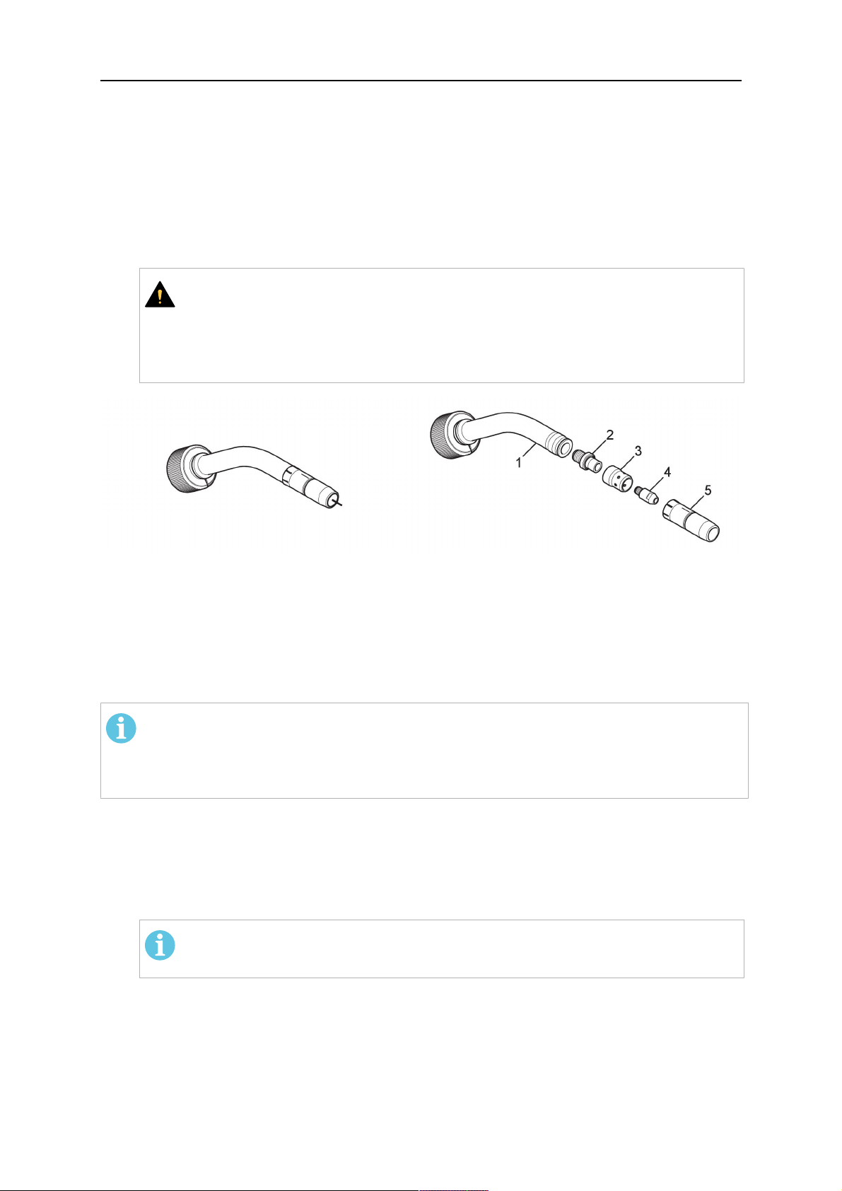
5.5.1 Torch neck equipment
The torch neck, see (1) in the illustration below, must always be equipped to suit the wire
diameter and material.
0463 373 101
- 46 -
© ESAB AB 2018
5 INSTALLATION
1. Select the correct wire guide, contact tip (4), tip holder (2), gas nozzle (5), and gas
diffuser/spatter protection (3). You will find an exact overview and possible alternative
equipment elements for various torch models in the spare parts list. Only use original
ESAB parts; only then is the fitting accuracy ensured.
2. Firmly tighten the tip holder and the contact tip using a suitable tool for example the
enclosed monkey wrench.
3. When using a split wire guide, remove the installed guide nipple including the o-ring
from the torch flange upon delivery if necessary (see section "Installing the neck
liner").
CAUTION!
The torch must be completely equipped before welding, especially the gas
diffuser and/or spatter protection and all necessary insulators have to be
installed according to the spare parts list. Welding without these items may
cause immediate destruction of the torch.
1 - Torch neck 4 - Contact tip
2 - Tip holder 5 - Contact tip
3 - Gas diffuser
5.5.2 Aristo RT torch neck installation
NOTE!
Check the O-rings on the flange of the torch neck before mounting. Replace the
O-rings if damaged or lost. Missing or faulty O-rings will lead to leaks of shielding
gas and coolant.
1. For hollow wrist systems, insert the torch into the torch mount in the correct
orientation, so that the locator pin fits into the slot of the RTKSC-2 or RTFLC-2
interface, see (A) in the illustration below. For standard systems, attach the torch to
the RT flange of the cable assembly, (B) in the illustration below.
Installation is only possible in the correct orientation.
2. Tighten the locking nut of the torch neck.
NOTE!
Only tighten by hand, never use tools or excessive force.
0463 373 101
- 47 -
© ESAB AB 2018

5 INSTALLATION
3. The correct seating of the torch can be checked by means of the window (1). If the
torch has been correctly mounted, no gap should be seen through the window (1).
5.6 Installing the wire guide for standard and hollow Wrist arm
Installing the wire guide
Choose the wire guide or liner depending on the filler wire material and diameter to be used,
see the spare parts list. Accurate performance of the system can only be guaranteed when
using original ESAB wire guides.
The recommended wire guide is the split wire guide, which consists of the neck liner and a
separate guide in the cable assembly. The front part of the wire guide, which is most
stressed, can be exchanged easily and independently of the cable assembly wire guide.
For correct installation, the following steps must be followed (example for Euro central
connector).
5.6.1 Installing the neck liner
The neck liner must be selected to fit the material and diameter of the welding wire, see the
spare parts list.
0463 373 101
- 48 -
© ESAB AB 2018

5 INSTALLATION
1. If present, remove the central guide nipple (1), from the torch neck using a hexagon
wrench (size 6 mm) or a large flat-blade screwdriver.
NOTE!
The guide nipple (1) can only be used with one-piece liners and must not be
used with the standard RT or hollow wrist system.
2. When replacing the neck liner:
Unfasten the sleeve nut and remove the torch neck.
Unfasten the liner nipple using a hexagon wrench (size 6 mm) and remove nipple and
liner from the torch neck.
3. Remove the gas nozzle and the contact tip.
4. Insert the new neck liner (2) into the torch. Carefully tighten the guide nipple using a
suitable tool, e.g. a hex-wrench (size 6 mm) or a large flat-blade screwdriver.
5. Cut the neck liner flush with the tip holder and remove the neck liner from the torch.
6. Install the contact tip.
7. Insert the neck liner again. It will be stopped by the contact tip. Measure the excess
liner sticking out of the neck.
8. Remove the liner again and shorten the front end by the measured length. Carefully
deburr the edge and make sure that the inner hole is not blocked.
9. Reinstall the neck liner and tighten the guide nipple in the neck.
5.6.2 Installing a split wire guide in the cable assembly
The correct liner must be inserted to suit the filler material and the wire diameter, see the
spare parts list.
The wire guide is inserted through the cable assembly from the rear, reaching the guide
nipple that is installed in the flange where the torch neck will be attached. The following
worksteps must be followed in order to correctly determine the wire guide length. (Example
for Euro central connector).
0463 373 101
- 49 -
© ESAB AB 2018

5 INSTALLATION
1. For standard RT system: Install the guide nipple (1) in the center hole of the neck
support flange, see illustration A below.
For hollow wrist system: Install the guide nipple (1) into the torch interface of the
RTKSC-2 / RTFLC-2 cover, see illustration B below.
2. Remove the sleeve nut (2) from the central connector, and remove the old wire guide.
3. Insert the wire guide through the central connection and push forwards as far as it will
go into the guide nipple (1), applying light pressure.
CAUTION!
Ensure that the wire guide has advanced right up to the stop at the front,
rotating and pushing forward gently.
4. Measure the excess length that needs to be cut from the wire guide.
5. Remove the wire guide again and shorten the front end by the measured length.
Steel liner: grind down the burred edges if needed.
Plastic liner: make a clean cut and chamfer the edges (e.g. with a pencil sharpener)
NOTE!
Make sure the inner opening of the liner is not obstructed by the cut wire end.
0463 373 101
- 50 -
© ESAB AB 2018

5 INSTALLATION
6. Reinstall the wire guide and attach the sleeve nut (2).
NOTE!
For hollow wrist systems where Infiniturn and Helix cable assemblies are
used, wire guides should be installed without tension so that the ends of the
liners may rotate freely.
Important note when using a plastic liner:
The wire channel between the drive rolls of the feeder and the central
connector of the torch must be fitted with a plastic liner. Depending on the
design of the feeder, a piece of plastic liner inserted into a brass guide tube
can be used.
During wire run-in, make sure that the wire is fed correctly into the plastic liner
of the torch. If necessary, remove the cable assembly from the feeder and
insert the wire, then reattach.
5.6.3 Installing a continuous wire guide in the cable assembly
Installing a steel liner
The wire guide is inserted through the cable assembly from the rear and reaches to the
contact tip. The following worksteps must be followed for the correct calculation of the length
(example for Euro central connector):
1. Install the torch (see section "Torch neck equipment").
2. Remove the gas nozzle and contact tip from the torch.
3. Remove the sleeve nut (D) from the Euro connector.
4. Push in the liner through the central connector and fix with the sleeve nut.
5. Cut off the liner flush with the nozzle holder. To determine the thread projection of the
contact tip, pull the liner backwards and screw in the contact tip.
6. Push the liner forwards as far as it will go to the contact tip applying light pressure on
the liner and measure the length to be shortened at the rear.
7. Now remove the liner again and cut the excess length measured off it’s front end. If
needed, grind down the burred edges. Make sure the inner opening of the liner is not
obstructed by the cut wire end.
8. The insulation of the liner must be removed after cutting off in the front area, such that
the insulation protrudes out of the RM2 flange by approx. 5 cm. For this, briefly
remove the torch neck.
9. Push the liner back in again and fix with the sleeve nut (D), see above. Re-install the
gas nozzle.
0463 373 101
- 51 -
© ESAB AB 2018

5 INSTALLATION
Installing a plastic liner
1. Mount the torch neck (see section "Torch neck equipment") and equip it with a gas
nozzle and contact tip.
2. Remove the sleeve nut (D) from the Euro connector.
3. Cleanly cut off the liner, slightly break the outer edges, point slightly (e.g. with a pencil
sharpener).
4. Insert the liner through the central connector into the cable assembly with fitted torch.
If it gets stuck, rotate the liner to free it and facilitate installation.
NOTE!
Make sure the liner is completely inserted by rotating it and slightly pushing it
forward, until you can feel it has reached its stop.
5. Mount the nipple (B) and the O-Ring (C), move it to the right position and fix it with the
sleeve nut (D) of the Euro central connector.
6. Measure the required overlap needed inside the wire feeder cabinet and cut the liner
accordingly.
5.7 Adjust the narrow gap contact tip
The adjusting tool RT42-NG is designed for the narrow gap torch necks RT42W-NG,
RT42G-NG and RT 82W-0°NG, torches with curved narrow gap contact tip. It facilitates the
precisely repeatable and fast changing of the curved contact tip.
NOTE!
The adjusting tool must be securely fastened to a stable base, in order to prevent
the position of the device in relation to the robot cannot change unintentionally. If the
exact orientation of the device is lost, the alignment of the contact tip used for the
elaboration of the welding programs can no longer be reproduced with precision.
Select a position within the operating range of the robot for orientation (alignment) of the
contact tip to the torch. Fasten the adjusting tool firmly to a base using the fastening grooves
provided for this purpose. Fastening material is not included with the adjusting tool. Select
fastening material (screws) to suit the existing conditions.
Save all motion sequences and stop positions required to change or align the wearing parts
to a separate robot program.
Before programming the welding tasks: plan at which orientation the contact tip is to stand in
relation to the torch. The torch must then be positioned in the desired rotational position and
the contact tip aligned using the adjusting device. Only then may the welding task be
programmed. If different orientations of the contact tip are required for various welding tasks,
the contact tip has to be aligned to the new position when the welding task is changed.
WARNING!
The gas nozzle and the torch head become very hot during welding. Always allow
the torch to cool down before replacing wearing parts or adjusting the contact tip.
0463 373 101
- 52 -
© ESAB AB 2018

5 INSTALLATION
Adjust the contact tip
Move the robot torch to a position parallel to
the opening of the adjusting tool (2). Maintain
a sufficient distance to the work table to be
able to comfortably remove the gas nozzle.
Define this position in your robot program as
the wearing parts change position (stop
position 1).
Remove the gas nozzle by pulling it
downwards. Remove the welding wire in the
contact tip if necessary.
Loosen the counter nut (4) of the contact tip
while counter-holding the nozzle holder at the
wrench flat (3).
Unscrew the contact tip including the counter
nut from the nozzle holder and replace the
nozzle holder if necessary.
Completely screw the counter nut (4) onto the
new contact tip. Screw the contact tip
including the counter nut into the nozzle
holder.
Align the contact tip until it is parallel to the
opening of the adjusting tool. If necessary,
slightly unscrew the contact tip so that it can
be easily turned in both directions.
0463 373 101
- 53 -
© ESAB AB 2018

5 INSTALLATION
NOTE!
The contact tip must be able to be
easily moved by hand in both
directions in order to enable the
threading of the adjusting tool.
Place the robot torch or contact tip directly in
front of the opening of the adjusting tool (2)
(stop position 2).
Insert it slowly from the front until it is
completely inserted into the device (stop
position 3).
The contact tip was aligned exactly in the
device during insertion. Now cautiously
tighten the counter nut (4) in this position,
while counter holding the nozzle holder at the
wrench flat.
Slowly move the robot torch out of the
adjusting gauge, return to stop position 1 and
push on the gas nozzle as far as it will go.
Allow the welding wire to run into the contact
tip and bring the robot arm into welding
position.
0463 373 101
- 54 -
© ESAB AB 2018

6 OPERATION
6 OPERATION
CAUTION!
Before starting the system, check the whole installation according to the
manufacturer's instructions and applicable safety regulations.
Check the following to make sure that the system has been installed correctly:
1. Are all parts securely attached (torch, torch mount, flanges, safety-off device, cable
assembly, and wire feeder cabinet)?
2. Are all media hoses connected correctly and protected from damage?
3. Is the EURO central connector or direct connector fastened tightly?
4. Is the cable assembly length correct and suitable for the installation and can the cable
rotate freely? The cable must not be bent sharply. Any risk of the cable getting caught
on another object must be eliminated.
5. Is the control cable of the safety-off circuit connected and functioning? Move torch by
hand to test (RTKSC-2 and RTKS-2 only).
6. Is the torch firmly attached and is it completely equipped?
7. Is the wire guide installed according to the manual?
8. Are all lines and tubes arranged so that they cannot be damaged or bent?
The wire run-in can now be started, either via the wire run-in pushbutton or via the wire run-in
at the feeder.
6.1 Important information for programming (hollow wrist system only)
Fast rotation of axis 6 of the robot will significantly stress the cable assembly. In certain
cases, this can lead to damage or destruction of the cable. In order to maximize the lifetime
of the cable, we strongly suggest respecting the following limitations when programming the
robot.
Position of axis 5 Max. rotational speed of axis 6
0 – 60° 100 % (no limitations)
60° – 80° 300°/sec (approximately 50 % of max. robot speed)
> 80° 120°/sec (approximately 20 % of max. robot speed)
NOTE!
The above values are only indications. For information on the exact rotational speed
limits, refer to the individual robot manual or contact the robot supplier.
To reposition the torch quickly, the robot arm may have to be slightly extended first to achieve
a bending angle of max. 60° of axis 5. In this position, the maximum available rotation speed
of axis 6 can be used.
When using the ESAB Helix cable assembly, the max. rotation of ±270° from the neutral
position must not be exceeded.
0463 373 101
- 55 -
© ESAB AB 2018

6 OPERATION
CAUTION!
While axis 5 is bent more than 60°, the rotational speed of the torch around axis 6
must be limited, see table above.
Otherwise, the cable assembly may be damaged.
0463 373 101
- 56 -
© ESAB AB 2018
7 SERVICE AND MAINTENANCE
7 SERVICE AND MAINTENANCE
WARNING!
Before performing maintenance on the system, the main power of the installation
must be turned off. Note the safety regulations at the beginning of this manual.
Damaged torches or cable assemblies must not be used! Known defects must be
repaired by qualified personnel prior to the next use of the equipment.
WARNING!
Risk of burn injuries! Gas nozzle and torch head get very hot during welding. Let the
torch cool down prior to maintenance work.
WARNING!
In order to prevent personal injuries or damage to your installation, follow these
instructions:
1. Repair of the RTKSC-2 or RTFLC-2 torch mount, the RTKS-2 safety-off
mechanism, the cable assembly, or the Infiniturn media coupling must only
be carried out by ESAB service support.
2. The Infiniturn media coupling must never be opened. It contains no
user-serviceable parts and will be destroyed by disassembly.
3. Never disassemble the RTKSC-2 or RTKS-2. This is a spring loaded
mechanism. Improper manipulation can lead to severe injury.
7.1 Mandatory checks and actions
Before every use:
• Check torch, contact tip, gas nozzle, neck liner, cables, and overall equipment for
general damage.
NOTE!
To minimize downtime, it is recommended to alternate between two torch necks,
always having a freshly equipped torch neck at hand and ready for use.
Every 8 hours of use (depending on application):
• Change contact tip.
Daily:
• Do a functional check by hand of the safety-off mechanism.
• Do a visual inspection for damage - e.g. bends or cracks.
• Verify the correct position of the wire feeder. The cable assembly must not be too tense
or sagging.
• Inspect the media connections and the Infiniturn media coupling for leakage.
• Perform cleaning and maintenance of the torch according to the torch manual.
Every 40 hours of use (depending on application):
• Change wire liners.
• Change neck liners.
Weekly or as needed depending on use:
• Remove the wire guide and check for wear and dirt deposits. Exchange if needed.
0463 373 101
- 57 -
© ESAB AB 2018

7 SERVICE AND MAINTENANCE
Monthly or more often at heavy use (i.e. more than 8 hours/day):
• Blow out the wire guide channel with compressed air (remove contact tip and wire
guide).
• Make sure that all screws are tightened.
• Inspect all connections and hoses for damages.
• Exchange after all 250 kg welded wire.
Damage of the electrical isolation must be repaired by trained personnel before the system
can safely be operated.
0463 373 101
- 58 -
© ESAB AB 2018

8 TROUBLESHOOTING
8 TROUBLESHOOTING
Fault Possible cause Action
Cannot feed
wire
Torch is getting
too hot
The welding wire has not been
straightened before feeding it into
the cable assembly
The torch and the cable assembly
are not equipped correctly for the
wire diameter and wire material
The wire guide is not correctly
inserted into the cable assembly
The contact tip blocked is blocked
with wire debris
The wire guide is worn
The wire feed is impeded by dirt
and debris in the torch
Contact tip or tip holder is not
tightened correctly
If necessary, pull the welding wire
out again, cut off and deburr the
end, and straighten the first 10 cm
of the wire. Then thread back into
the cable assembly.
Check the guide (cable assembly
and torch neck) and contact tip.
Pull out the wire guide from the
EURO connector a little. When
inserting the wire guide, you should
feel the last centimeters slip into the
guide nipple in the torch interface.
Otherwise the wire guide may be
too short and not fully inserted.
Replace the contact tip and/or wire
guide and blow out the torch neck,
wire guide conduit and wire guide
with compressed air.
Use a suitable tool for tightening
hand-tight.
Wire feeding
problems
Cooling system is not working well Check water flow, filling level and
cleanliness.
Cooling system is not correctly
connected
Check connections (water inlet and
return).
Torch overstrained Observe technical data. If needed,
choose a different type.
Cable assembly defective Check cables, tubes and
connections.
Contact tip is worn Exchange contact tip.
Liner is worn / dirty Check the liner; blow out. Exchange
if needed.
Consumables used are not suitable
Check spare part list.
for the wire diameter or material
Wire feeder not set-up properly Check the wire feeding rolls, the
contact pressure and the spool
brake.
Cable assembly is bent or laid out in
too small radii
Check the cable assembly for
damages. Can the liner be inserted
easily? Install as instructed. See the
section "Installing the cable
assembly".
0463 373 101
Wire is contaminated Use a cleaning felt.
- 59 -
© ESAB AB 2018

8 TROUBLESHOOTING
Fault Possible cause Action
Wire feed stops
during welding
Welding
process is
stopping
Pores in the
seam
Wire spool is empty Check the quantity of the welding
wire on the spool in the wire feeder.
Wire blockage in the cable
assembly
Check wire feed (possibly too fast),
check the contact tip for
contamination/clogging, and clean
or replace the contact tip if required.
Wire burn back into the contact tip
Replace the contact tip.
or worn contact tip
Safety-off mechanism has triggered. Search for collision points and
prevent them. Check control line for
a loose contact.
Gas swirl caused by spatter
adherence
Too small or extremely high gas
flow in the torch
Clean the torch head, use gas
diffuser / spatter protection.
Check flow rate with measurement
tool.
Gas supply defective Check flow rate and possible
leakage.
Moisture or contamination on the
wire or on the work piece
Check the wire and the work piece.
Use less or different anti-spatter
liquid.
Arc is not stable Contact tip is worn Exchange contact tip.
Wrong welding parameters Check the set-up of the welding
equipment.
Insufficient electrical connections in
the circuit
Check all electrical connections
(incl. ground cable) between the
power source torch or work piece
for firm seating.
0463 373 101
- 60 -
© ESAB AB 2018

9 ORDERING SPARE PARTS
9 ORDERING SPARE PARTS
CAUTION!
Repair and electrical work should be performed by an authorised ESAB service
technician. Use only ESAB original spare and wear parts.
The ESAB RT torches RTKS-2, RTFL-2, RT-KSC-2, RT-FLC-2, RT42, RT52, RT62,
RT72, RT82, RT42-NG, and RT82WNG are designed and tested in accordance with
international and European standards IEC/EN 60974-7. It is the obligation of the service unit
that carried out the service or repair work to make sure that the product still conforms to said
standard.
Spare parts and wear parts can be ordered through your nearest ESAB dealer, see the back
cover of this document. When ordering, please state product type, serial number, designation
and spare part number in accordance with the spare parts list. This facilitates dispatch and
ensures correct delivery.
0463 373 101
- 61 -
© ESAB AB 2018

ESAB AB, Lindholmsallén 9, Box 8004, 402 77 Gothenburg, Sweden, Phone +46 (0) 31 50 90 00
http://manuals.esab.com
For contact information visit esab.com
 Loading...