


RT Robo Welding Torch System
RTKS-2, RTFL-2, KSC-2, FLC-2, RT42, RT52,
RT62, RT72, RT82, RT42-NG, RT82WNG
Instrukcijos
0463 373 101 LT 20181227


TURINYS
1
SAUGA ........................................................................................................ 5
1.1 Simbolių reikšmė.................................................................................... 5
1.2 Saugos priemonės ................................................................................. 5
2
GARANTIJA ................................................................................................ 8
2.1 Numatyto naudojimo sąlygos ............................................................... 8
3
ĮVADAS ........................................................................................................ 9
3.1 Suvirinimo degiklio sistemų apžvalga ................................................. 9
4
TECHNINIAI DUOMENYS ........................................................................... 11
4.1 Suvirinimo degiklio kaklelis .................................................................. 11
4.2 Vardinė įtampa........................................................................................ 12
4.2.1 Aušinimo kontūro apribojimai ............................................................... 12
4.3 Degiklio tvirtinimo detalė....................................................................... 13
4.3.1 Standartinei RT sistemai skirtos degiklio tvirtinimo detalės.................. 13
4.3.1.1 RTKS-2 apsauginis mechanizmas ................................................... 14
4.3.1.2 RTFL-2 tarpinė jungė........................................................................ 14
4.3.2 Sistemai su tuščiaviduriu riešu skirtos degiklio tvirtinimo detalės ........ 15
4.3.2.1 RTKSC-2 G/W degiklio tvirtinimo detalė su apsauginiu
mechanizmu ......................................................................................
4.3.2.2 RTFLC-2 G/W standi degiklio tvirtinimo detalė................................. 17
4.4 Adapterio jungės .................................................................................... 18
4.5 Kabelio įtaisai ......................................................................................... 18
4.5.1 Standartinės RT sistemos kabelio įtaisai.............................................. 18
4.5.2 Sistemoms su tuščiaviduriu riešu skirti kabelio įtaisai .......................... 19
5
INSTALLATION............................................................................................ 21
5.1 RTKS-2 standard arm installation........................................................ 21
5.1.1 RTKS-2 safety-off mechanism............................................................. 21
5.1.1.1 Torch installation with adjustable mount ............................................ 22
5.1.2 Standard arm cable assembly for KS-2 and FL-2 ................................ 24
5.1.3 RTKS-2 wire feeder connection........................................................... 25
5.1.4 RTKS-2 electrical connections ............................................................ 26
5.1.4.1 RTKS-2 safety-off mechanism connection ....................................... 26
5.1.5 RTKS-2 Torch installation.................................................................... 27
5.2 RTFL-2 standard arm installation ........................................................ 28
16
5.2.1 RTFL-2 rigid mount.............................................................................. 28
5.2.2 RTFL-2 torch installation ..................................................................... 30
5.3 RTKSC-2 hollow wrist system installation.......................................... 30
5.3.1 RTKSC-2 mount with safety off mechanism........................................ 30
5.3.2 Mounting the cable assembly............................................................... 31
5.3.2.1 RTKSC-2 feeder cabinet connections .............................................. 32
5.3.3 RTKSC-2 cable assembly ................................................................... 34
5.3.3.1 RTKSC-2 cable assembly installation .............................................. 34
0463 373 101 © ESAB AB 2018

TURINYS
5.3.3.2 RTKSC-2 electrical connections....................................................... 37
5.3.4 RTKSC-2 torch installation .................................................................. 38
5.4 RTFLC-2 installation.............................................................................. 39
5.4.1 RTFLC-2 mount................................................................................... 39
5.4.2 RTFLC-2 wire feeder connection......................................................... 39
5.4.2.1 Feeding through the robot arm.......................................................... 39
5.4.2.2 RTFLC-2 feeder cabinet connections............................................... 40
5.4.3 RTFLC-2 cable assembly .................................................................... 42
5.4.3.1 RTFLC-2 cable assembly installation ............................................... 42
5.4.4 RTFLC-2 electrical connections .......................................................... 45
5.4.4.1 RTFLC-2 hollow wrist system with Infiniturn cable assembly........... 45
5.4.4.2 RTFLC-2 hollow wrist system with Helix cable assembly................. 46
5.5 Torch installation.................................................................................... 46
5.5.1 Torch neck equipment .......................................................................... 46
5.5.2 Aristo RT torch neck installation........................................................... 47
5.6 Installing the wire guide for standard and hollow Wrist arm ............. 48
5.6.1 Installing the neck liner......................................................................... 48
5.6.2 Installing a split wire guide in the cable assembly ................................ 49
5.6.3 Installing a continuous wire guide in the cable assembly ..................... 51
5.7 Adjust the narrow gap contact tip ........................................................ 52
6
OPERATION ................................................................................................ 55
6.1 Important information for programming (hollow wrist system only) 55
7
TECHNINĖ PRIEŽIŪRA............................................................................... 57
7.1 Privalomos patikros ir veiksmai ........................................................... 57
8
GEDIMŲ ŠALINIMAS .................................................................................. 59
9
ATSARGINIŲ DALIŲ UŽSAKYMAS............................................................ 61
Gamintojas pasilieka teisę keisti specifikacijas be perspėjimo.
0463 373 101 © ESAB AB 2018

1 SAUGA
1 SAUGA
1.1 Simbolių reikšmė
Kaip naudojama šiame vadove: Reiškia „Dėmesio“! Būkite atsargūs!
PAVOJUS!
Reiškia tiesiogiai gresiantį pavojų, kuris, jei jo nebus išvengta, nedelsiant
sukels sunkų arba mirtiną asmens sužalojimą.
ĮSPĖJIMAS!
Reiškia galimą pavojų, kuris gali sukelti asmens sužalojimą arba mirtį.
DĖMESIO!
Reiškia pavojus, kurie gali sukelti nesunkų asmens sužalojimą.
ĮSPĖJIMAS!
Prieš naudodami perskaitykite naudojimo instrukciją ir
atsižvelkite į visose etiketėse nurodytą informaciją,
darbdavio saugias praktikas ir saugos duomenų lapų
(SDS) informaciją.
1.2 Saugos priemonės
Kad su įranga ar šalia jos dirbantys asmenys laikytųsi atitinkamų saugos priemonių, atsako
ESAB įrangos naudotojai. Saugos priemonės turi tenkinti šio tipo įrangai keliamus
reikalavimus. Be standartinių taisyklių, taikomų darbo vietoje, atsižvelkite į toliau pateikiamas
rekomendacijas.
Visus darbus turi atlikti specialiai parengti darbuotojai, gerai išmanantys įrangos veikimą.
Netinkamai naudojama įranga gali lemti pavojingas situacijas, dėl kurių gali susižeisti
naudotojas arba sugesti įranga.
1. Kiekvienas asmuo, naudojantis įrangą, turi žinoti:
○ kaip ji veikia
○ avarinių išjungiklių vietas
○ jos funkcijas
○ susijusias saugos priemones
○ suvirinimo, pjovimo ar kitus su šia įranga atliekamus veiksmus
2. Naudotojas turi pasirūpinti, kad:
○ pradėjus dirbti, įrangos naudojimo vietoje nebūtų pašalinių asmenų
○ visi yra saugūs atliekant elektros lanko taktą arba pradėjus darbą su įranga
3. Darbo vieta turi būti:
○ tinkama tam tikslui
○ be skersvėjų
0463 373 101
- 5 -
© ESAB AB 2018

1 SAUGA
4. Asmeninės apsaugos priemonės:
○ Visuomet naudokite rekomenduojamas asmens apsaugos priemones, pvz.,
apsauginius akinius, ugniai atsparius drabužius, apsaugines pirštines
○ Nedėvėkite palaidų daiktų, pvz., šalikų, apyrankių, žiedų ir t. t., kurie gali įstrigti ir
nudeginti
5. Bendrosios saugos priemonės:
○ Patikrinkite, ar grįžtamasis kabelis tvirtai prijungtas
○ Darbus su aukštos įtampos įranga gali atlikti tik kvalifikuotas elektrikas
○ Atitinkama gaisro gesinimo įranga turi būti aiškiai pažymėta ir laikoma netoliese
○ Darbo metu negalima įrangos sutepti ir atlikti kitų priežiūros darbų
ĮSPĖJIMAS!
Virindami ir pjaudami elektros lanku galite susižaloti patys ir sužaloti kitus. Virindami
ir pjaudami imkitės atsargumo priemonių.
ELEKTROS SMŪGIS gali būti mirties priežastis
• Prietaisą sumontuokite ir įžeminkite atsižvelgdami į naudojimo instrukciją.
• Nelieskite veikiančių elektrinių dalių arba elektrodų plika oda, šlapiomis
pirštinėmis arba šlapiais drabužiais.
• Izoliuokite save nuo darbo vietos ir nuo grindų.
• Įsitikinkite, kad jūsų darbinė padėtis yra saugi.
ELEKTRINIAI IR MAGNETINIAI LAUKAI gali būti pavojingi sveikatai
• Suvirintojai, turinys širdies simuliatorius, prieš pradėdami virinti turėtų
pasitarti su savo gydytoju. EMF gali trikdyti kai kurių širdies stimuliatorių
darbą.
• EMF veikimas gali turėti sveikatai kitą poveikį, kuris nežinomas.
• Siekdami sumažinti EMF poveikį, suvirintojai turėtų atlikti toliau nurodytas
procedūras:
○ Elektrodo ir darbinius kabelius nutiesti toje pačioje kūno pusėje. Jei
įmanoma, pritvirtinti juos lipnia juosta. Nebūkite tarp degiklio ir
darbinių kabelių. Niekuomet nevyniokite degiklio arba darbinio
kabelio apie savo kūną. Laikykite suvirinimo maitinimo šaltinį ir
kabelius kuo toliau nuo kūno.
○ Prijunkite darbinį kabelį kuo arčiau apdirbamos detalės suvirinimo
vietos.
DŪMAI IR DUJOS gali būti pavojingi sveikatai
• Nelaikykite galvos garų debesyje.
• Naudokite ventiliaciją, ištraukimą ties lanku arba abu, kad pašalintumėte
smalkes ir dujas iš kvėpavimo zonos ir visos aplinkos.
ELEKTROS LANKO SPINDULIAI gali pažeisti akis ir nudeginti odą
• Apsaugokite savo akis ir odą. Naudokite tinkamą virinimo kaukę ir lęšius su
filtrais bei dėvėkite apsauginius drabužius.
• Apsaugokite aplinkinius įrengdami atitinkamus ekranus bei uždangas.
0463 373 101
TRIUKŠMAS. Per didelis triukšmas gali pažeisti klausos organus
Apsaugokite savo ausis. Naudokite ausines ar kitas klausos apsaugos
priemones.
- 6 -
© ESAB AB 2018

1 SAUGA
JUDANČIOS DALYS gali sužeisti
• Visas dureles, skydus ir gaubtus laikykite uždarę ir tinkamai užfiksavę. Jei
reikia atlikti priežiūros arba remonto darbus, gaubtus turėtų nuimti tik
kvalifikuoti specialistai. Baigę priežiūros darbus ir prieš paleisdami variklį,
pritvirtinkite skydus arba gaubtus ir uždarykite dureles.
• Prieš montuodami arba prijungdami įrenginį, sustabdykite variklį.
• Nekiškite rankų, plaukų, palaidų drabužių ir įrankių prie judančių dalių.
GAISRO PAVOJUS
• Kibirkštys (tiškalai) gali sukelti gaisrą. Prieš tai patikrinkite, ar arti nėra
degių medžiagų.
• Nenaudokite uždarytoms talpykloms.
GEDIMAS. Įvykus gedimui, į pagalbą pasikvieskite specialistą.
SAUGOKITE SAVE IR KITUS!
DĖMESIO!
Šis gaminys skirtas tik virinti lanku.
ĮSPĖJIMAS!
Nenaudokite maitinimo šaltinio užšalusiems vamzdžiams atšildyti.
DĖMESIO!
„Class A“ tipo įranga neskirta naudoti gyvenamosiose
patalpose, kur elektros srovė tiekiama viešaisiais
žemosios įtampos elektros tinklais. Gali kilti sunkumų
tokiose patalpose nustatant elektromagnetinį „class A“
įrangos suderinamumą dėl laidais sklindančių, taip pat ir
spinduliuojamų trikdžių.
PASTABA!
Nebenaudojamą elektroninę įrangą pateikite
perdirbimo įmonei!
Pagal Europos Direktyvą 2012/19/EB dėl elektrinių ir
elektroninių atliekų ir jos pritaikymą pagal nacionalinius
įstatymus, nebetinkama naudoti elektros ir (arba)
elektroninė įranga turi būti pateikta perdirbimo įmonei.
Esate už įrangą atsakingas asmuo, todėl įsipareigojate
gauti informacijos apie patvirtintas surinkimo stotis.
Dėl išsamesnės informacijos kreipkitės į artimiausią
ESAB platintoją.
ESAB turi didelį suvirinimo priedų ir asmens apsaugos priemonių asortimentą.
Norėdami gauti užsakymo informacijos, kreipkitės į vietinį ESAB platintoją arba
apsilankykite mūsų svetainėje.
0463 373 101
- 7 -
© ESAB AB 2018

2 GARANTIJA
2 GARANTIJA
Prieš pristatymą mūsų gaminiai yra kruopščiai patikrinami. ESAB patvirtina, kad visi
produktai pristatymo metu yra be medžiagų ir gaminimo defektų ir veikia pagal numatytąją
paskirtį.
ESAB suteikia garantiją dėl medžiagų ir gaminimo defektų pagal teisinius reikalavimus.
Vartojimo reikmenims garantija netaikoma.
Garantija netaikoma jokiems pažeidimams arba funkciniams defektams, atsiradusiems dėl:
• per didelės produkto apkrovos, netinkamo naudojimo arba naudojimo ne pagal paskirtį;
• susidūrimų ar nelaimingų atsitikimų;
• nesilaikymo šiose naudojimo instrukcijose pateiktų nurodymų;
• netinkamo montavimo arba surinkimo;
• nepakankamos priežiūros;
• produkto originalios būsenos modifikavimo;
• cheminio poveikio;
• įprasto dėvėjimosi.
ESAB neprisiima jokios atsakomybės, išskyrus sugedusių dalių pakeitimą arba remontą.
2.1 Numatyto naudojimo sąlygos
1. Produktas yra skirtas naudoti pramoniniams ir komerciniams tikslams, jį gali naudoti
tik parengti darbuotojai. Gamintojas nėra atsakingas už bet kokią žalą arba
nelaimingus atsitikimus, kilusius netinkamai naudojant.
2. „Aristo® RT“ robotizuoto suvirinimo sistema yra suprojektuota ir pagaminta taikant
pažangiausius metodus ir yra saugi bei patikima, jei ją naudoja, montuoja ir prižiūri
parengti darbuotojai. Būtina laikytis šiame dokumente pateiktų montavimo, darbo ir
priežiūros instrukcijų.
3. Tik parengti darbuotojai gali montuoti, naudoti ir prižiūrėti „Aristo® RT“ robotizuoto
suvirinimo sistemą. Būtina laikytis šiame vadove pateiktų montavimo, darbo ir
priežiūros reikalavimų.
4. „Aristo® RT“ robotizuoto suvirinimo sistemą galima naudoti ik gamintojo numatytiems
tikslams, atsižvelgiant į techninius duomenis ir kartu su automatinėmis apdorojimo
sistemomis. Degiklio tipas turi atitikti suvirinimo pobūdį.
5. „Aristo® RT“ robotizuoto suvirinimo sistema suprojektuota taip, kad ją būtų galima
naudoti be papildomos įrangos. Neleidžiama sistemos naudoti kartu su kitų gamintojų
komponentais.
6. RT KS-2 ir RT KSC-2 gali būti naudojami tik kaip avarinio išjungimo mechanizmai,
atsižvelgiant į jų techninius duomenis ir kartu su RT standartinės rankos kabelio įtaisu
(KS-2), „Infiniturn“ arba „Helix“ (KSC-2), ESAB adapterio junge, įskaitant RT degiklio
tvirtinimo detales (KS-2) ir „Aristo RT“ suvirinimo degiklį.
7. Į prapūtimo dujas negalima įmaišyti alyvos arba nuo purslų apsaugančio skysčio.
ESAB negali užtikrinti cheminio atsparumo šioms medžiagoms. ESAB rekomenduoja
naudoti ESAB purkštuvą, kuris leidžia naudoti mažesnį nuo purslų apsaugančio
skysčio kiekį ir tokiu būdu saugoti aplinką.
8. Gabenimo, laikymo ir naudojimo metu produktas turi būti sausas ir apsaugotas nuo
drėgmės.
9. Sistema pritaikyta aplinkos temperatūros intervalui nuo 5 °C iki 40 °C (nuo 41 °F iki
104 °F). Nesilaikant šių apribojimų, būtina imtis veiksmų. Jei yra šalčio pavojus,
naudokite tinkamą aušinimo skystį.
0463 373 101
- 8 -
© ESAB AB 2018

3 ĮVADAS
3 ĮVADAS
RT suvirinimo degiklio sistemos skirtos visiškai automatiniam MIG/MAG suvirinimui
naudojant robotus. Sistemą sudaro įvairūs „Aristo RT“ degiklio kakleliai, skirti naudoti kartu
su robotais, degiklio tvirtinimo detalės, robotams pritaikyti kabelio įtaisai ir apsaugos
funkcijos, skirtos apsaugoti sistemą nuo pažeidimų susidūrimo atveju.
Standartinę RT suvirinimo sistemą nuo susidūrimo saugo RTKS-2, t.y. mechaninis
spyruoklinis apsauginis mechanizmas. Jį galima pakeisti RTFL-2 mechanizmu, kuris leidžia
naudoti roboto valdymo sistemos įspėjimo apie susidūrimą funkciją. Standartinę RT
suvirinimo sistemą galima naudoti su įvairių tipų kabelio įtaisais.
RTKSC-2 ir RTFLC-2 degiklio tvirtinimo detalės su „Infiniturn“ arba „Helix“ kabelio įtaisais
yra skirtos sudėtingiems suvirinimo darbams pritaikytoms robotizuotoms suvirinimo
sistemoms su tuščiaviduriu riešu. RTKSC-2 degiklio tvirtinimo detalės apsauginis
mechanizmas leidžia dideliu kampu pakreipti degiklį įvykus susidūrimui. „Infiniturn“ ir „Helix“
kabelio įtaisus paprasta sumontuoti, todėl galite turėti ypač patikimą ir tikslų manevravimą
užtikrinančią sistemą.
Kartu su išbandytais „Aristo RT“ robotizuoto suvirinimo degikliais šios dalys sudaro ypač
patikimą ir ilgai tarnaujančią sistemą, kurios beveik nereikia prižiūrėti.
Instrukcijų vadovas pateikiamas kartu su degiklio tvirtinimo detalėmis ir kabelio įtaisais.
ESAB užsakymo numeriai, galimi priedai, atsarginės dalys ir keičiamos dalys
išvardytos atsarginių dalių sąraše.
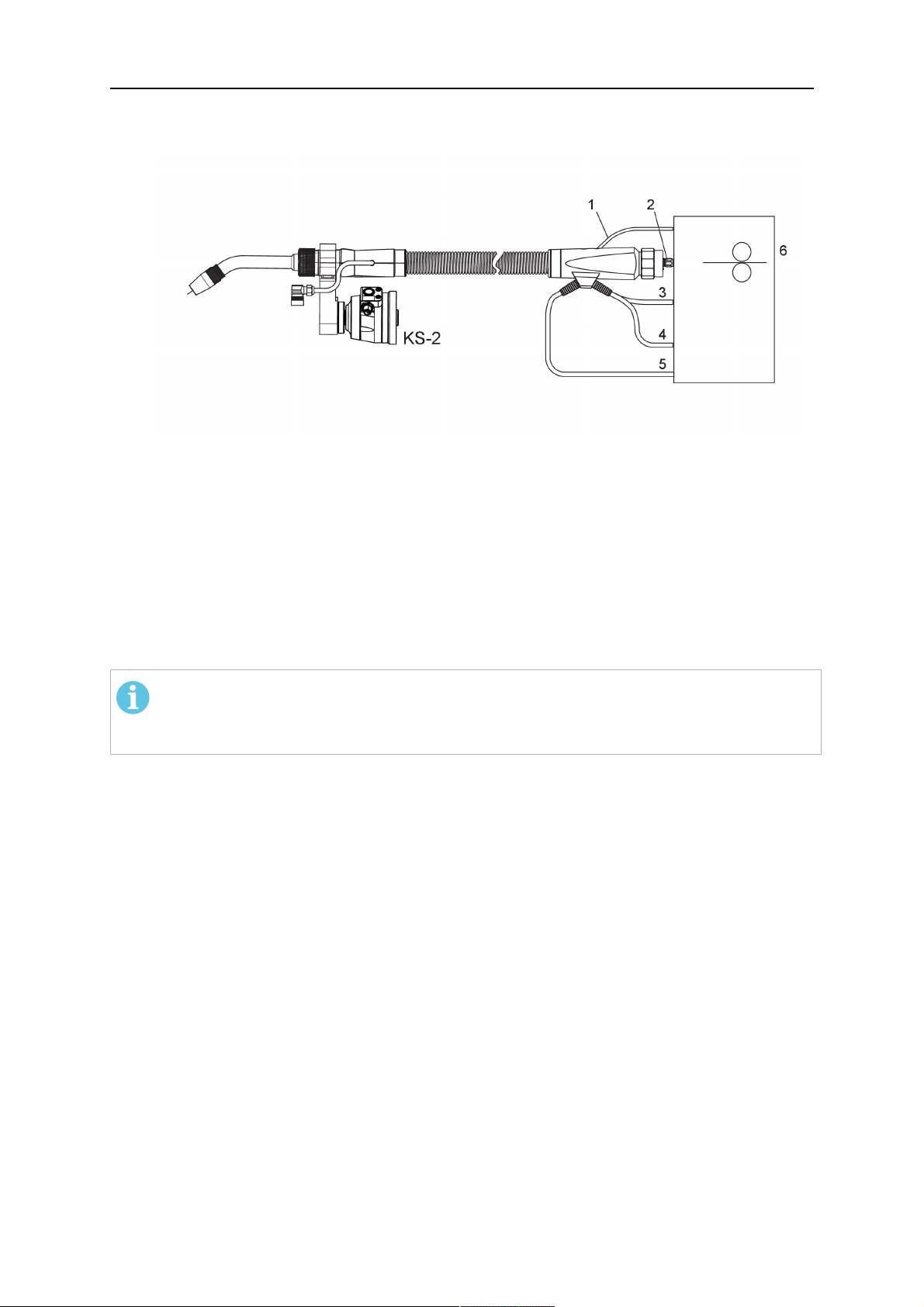
3.1 Suvirinimo degiklio sistemų apžvalga
Standartinė RT sistema
Išsamų aprašą žr. atitinkamoje TECHNINIŲ
DUOMENŲ skyriaus dalyje:
1. Degiklio kaklelis
Žr. „Suvirinimo degiklis“.
2. Kabeliai
Žr. „Standartinės RT sistemos
kabelio įtaisai“.
3. Degiklio tvirtinimo detalė
Žr. „Standartinės RT sistemos
degiklio tvirtinimo detalės“.
4. RTKS-2 apsauginis mechanizmas
Žr. „RTKS-2 apsauginis
mechanizmas“.
5. RTFL-2 tarpinė jungė
Žr. „RTFL-2 tarpinė jungė“.
6. Adapterio jungė (jei reikia)
Žr. „Adapterio jungės“.
0463 373 101
- 9 -
© ESAB AB 2018

3 ĮVADAS
Sistema su tuščiaviduriu riešu
Išsamų aprašą žr. atitinkamoje TECHNINIŲ
DUOMENŲ skyriaus dalyje:
1. Degiklio kaklelis
Žr. „Suvirinimo degiklis“.
2. Degiklio tvirtinimo detalė
RTKSC-2
Žr. „RTKSC-2 degiklio tvirtinimo
detalė su apsauginiu mechanizmu“.
3. Degiklio tvirtinimo detalė
RTFLC-2
Žr. „RTFLC-2 “standi degiklio
tvirtinimo detalė.
4. Adapterio jungė
Žr. „Adapterio jungės“.
5. „Helix“ arba „Infiniturn“ kabelio
įtaisas
Žr. „Sistemoms su tuščiaviduriu
riešu skirti kabelio įtaisai“.
0463 373 101
- 10 -
© ESAB AB 2018

4 TECHNINIAI DUOMENYS
4 TECHNINIAI DUOMENYS
4.1 Suvirinimo degiklio kaklelis
Degiklio modelį pasirinkite atsižvelgdami į atliekamus suvirinimo darbus. Būtina atsižvelgti į
darbo ciklą ir apkrovą, aušinimo metodą ir vielos skersmenį. Jei taikomi aukštesni
reikalavimai, pvz., dėl įkaitusių ruošinių ar stipraus šilumos atspindžio ties kampais, į juos
atsižvelkite ir rinkitės suvirinimo degiklį su atitinkamu galios rezervu.
RT suvirinimo degikliai yra skirti naudoti su CE reikalavimus atitinkančiais suvirinimo
šaltiniais, skirtais lankinio suvirinimo lydžiuoju elektrodu inertinėse dujose (MIG), lankinio
suvirinimo lydžiuoju elektrodu aktyviosiose dujose (MAG) ir MIG litavimo procesams
naudojant parduodamas apskrito profilio vielas. Nenaudokite degiklio kitiems procesams.
Plieno suvirinimui naudojant impulsinį lankinį suvirinimą arba aliuminio suvirinimui turi būti
naudojamas RT82W vandeniu aušinamas degiklis.
Galimus degiklių modelius žr. toliau.
Degiklio modelis Aušinimo metodas Apsauginės dujos Srovė
RT42G Aušinamas dujomis CO
Aušinamas dujomis 300A / 100%
Aušinamas dujomis Mišinys 350A / 60%
Aušinamas dujomis 250A / 100%
RT42W Aušinamas vandeniu CO
Aušinamas vandeniu 420A / 100%
Aušinamas vandeniu Mišinys 350A / 60%
Aušinamas vandeniu 350A / 100%
RT52G Aušinamas dujomis CO
Aušinamas dujomis 300A / 100%
Aušinamas dujomis Mišinys 350A / 60%
Aušinamas dujomis 250A / 100%
RT52W Aušinamas vandeniu CO
Aušinamas vandeniu 470A / 100%
Aušinamas vandeniu Mišinys 400A / 60%
Aušinamas vandeniu 400A / 100%
RT62G Aušinamas dujomis CO
Aušinamas dujomis 340A / 100%
2
2
2
2
2
420A / 60%
420A / 60%
420A / 60%
470A / 60%
500A / 60%
Aušinamas dujomis Mišinys 420A / 60%
Aušinamas dujomis 290A / 100%
RT62W Aušinamas vandeniu CO
Aušinamas vandeniu 530A / 100%
Aušinamas vandeniu Mišinys 450A / 60%
Aušinamas vandeniu 450A / 100%
0463 373 101
- 11 -
2
530A / 60%
© ESAB AB 2018

4 TECHNINIAI DUOMENYS
Degiklio modelis Aušinimo metodas Apsauginės dujos Srovė
RT72G Aušinamas dujomis CO
2
480A / 60%
Aušinamas dujomis 320A / 100%
Aušinamas dujomis Mišinys 400A / 60%
Aušinamas dujomis 270A / 100%
RT72W Aušinamas vandeniu CO
2
480A / 60%
Aušinamas vandeniu 430A / 100%
Aušinamas vandeniu Mišinys 480A / 60%
Aušinamas vandeniu 430A / 100%
RT82W Aušinamas vandeniu CO
2
600A / 60%
Aušinamas vandeniu 600A / 100%
Aušinamas vandeniu Mišinys 550A / 60%
Aušinamas vandeniu 550A / 100%
Degiklio srovės ir darbo ciklo reikšmės nurodytos 10 minučių ciklui.
Techniniai duomenys pateikti laikant, kad dirbama įprastai ir naudojamos standartinės
keičiamos (atsarginės) dalys. Atliekant impulsinį lankinį suvirinimą su metalo pernešimu,
degiklio srovės reikšmės yra mažesnės.
Temperatūros intervalas Laikymas: -15-50°C (5-122°F)
Darbas: 5–40°C (41–104°F)
Prapūtimo dujos Maks. 10 barų, atskira dujų žarna
Bendras svoris (degiklio kaklelis, apsauginis
Apie 5 kg
mechanizmas, degiklio tvirtinimo detalė ir 1 m
kabelio įtaisas)
4.2 Vardinė įtampa
Maks. leidžiamoji įtampa / stipris
Visa suvirinimo degiklio sistema 141 V (didžiausia reikšmė suvirinant)
RTKS-2 apsauginė valdymo grandinė
RTKS-2 mygtukinis jungiklis
RT KSC-2 apsauginė valdymo grandinė 48 V
Naudojant purkštuko jutimo funkciją su
standartiniu kabelio įtaisu
Naudojant purkštuko jutimo funkciją su
„Helix“ arba „Infiniturn“ kabelio įtaisais
24 V / 1 A
48 V / 0,1 A
50 V / 5 A
(Apkrova esant vardinei srovei leidžiama ne
ilgiau nei 1 minutę)
50 V / 5 A
(Apkrova esant vardinei srovei leidžiama ne
ilgiau nei 1 minutę)
Nurodytos reikšmės įprasto darbo metu.
Kebelio įtaisų reikšmes žr. dalyje „Kabelio įtaisai“.
4.2.1 Aušinimo kontūro apribojimai
Taikoma tik vandeniu aušinamai versijai.
0463 373 101
- 12 -
© ESAB AB 2018

4 TECHNINIAI DUOMENYS
Min. vandens srautas: 1,0 l/min. (1,1 kvart./min.)
Min. vandens slėgis: 2,5 baro (36,3 PSI)
Maks. vandens slėgis: 3,5 baro (50,8 PSI)
Įleidžiamo srauto
temperatūra:
Grąžinamo srauto
temperatūra:
Maks. 40 °C (104 °F)
Maks. 60 °C (140 °F)
Aušinimo galia: Min. 1000 W, atsižvelgiant į panaudojimą
DĖMESIO!
Kai grąžinamo srauto temperatūra yra didesnė nei 60 °C (140 °F), gali būti
pažeistas arba sugadintas kabelio įtaisas.
4.3 Degiklio tvirtinimo detalė
Reikalingas degiklio tvirtinimo detalės tipas priklauso nuo RT suvirinimo degiklio sistemos
konstrukcijos ir pasirinktų apsauginių įrenginių, žr. dalį „Suvirinimo degiklio sistemų
apžvalga“.
Komponentas Apytikslis svoris
Degiklio tvirtinimo detalė (standartinei
sistemai)
RTKS-2 apsauginis mechanizmas
(standartinei sistemai)
0,43 kg
0,85 kg
RTFL-2 tarpinė jungė (standartinei sistemai) 0,35 kg
RTKSC-2 degiklio tvirtinimo detalė (sistemai
1,90 kg
su tuščiaviduriu riešu)
RTFLC-2 standi degiklio tvirtinimo detalė
1,22 kg
(sistemai su tuščiaviduriu riešu)
Robotizuoto suvirinimo degiklis 0,66 kg
4.3.1 Standartinei RT sistemai skirtos degiklio tvirtinimo detalės
Standartinėms RT sistemoms skirta degiklio tvirtinimo detalė montuojama ant RTKS-2
apsauginio mechanizmo (arba ant RTFL-2 tarpinės jungės) ir užfiksuoja kabelio įtaisą bei
prijungto degiklio kaklelį.
Degiklio tvirtinimo detalę pasirinkite atsižvelgdami į degiklio tipą ir geometriją. Gali būti
naudojamos skirtingų tipų tvirtinimo detalės. Informacijos apie standartinėms RT sistemoms
tinkamas degiklio tvirtinimo detales žr. atsarginių dalių sąraše.
0463 373 101
- 13 -
© ESAB AB 2018

4 TECHNINIAI DUOMENYS
Standartiniams robotams su ranka skirta degiklio tvirtinimo detalė
4.3.1.1 RTKS-2 apsauginis mechanizmas
RTKS-2 apsauginis mechanizmas yra spyruoklinis įrenginys, saugantis robotą ir degiklio
sistemą susidūrimo atveju.
PASTABA!
Neardykite RTKS-2.
4.3.1.2 RTFL-2 tarpinė jungė
Standžią tarpinę jungę RTFL-2 galima naudoti vietoje RTKS-2, jei robotas turi elektroninę
įspėjimo apie susidūrimą sistemą.
0463 373 101
- 14 -
© ESAB AB 2018

4 TECHNINIAI DUOMENYS
4.3.2 Sistemai su tuščiaviduriu riešu skirtos degiklio tvirtinimo detalės
Naudojant sistemą su tuščiaviduriu riešu, „Aristo RT“ suvirinimo degiklio kakleliai yra jungiami
prie degiklio tvirtinimo detalės KSC-2 arba FLC-2.
Degiklio tvirtinimo detalė RTKSC-2 leidžia pakreipti degiklį susidūrimo atveju. Tuo pačiu
metu sudaromas elektrinis kontaktas, signalizuojantis roboto valdymo sistemai sustoti.
Ištaisius klaidą, labai tiksliai atkuriama pradinė geometrija ir degiklio centrinis taškas (CT).
Sistemos veikimo principas yra išimtinai mechaninis; joje įrengta spyruoklė.
Degiklio tvirtinimo detalėje RTFLC-2 nėra integruotos apsauginės funkcijos.
Sistemoms su tuščiaviduriu riešu rekomenduojama naudoti RTKSC-2 G/W (arba RTFLC-2
G/W). Šią degiklio tvirtinimo detalę galima naudoti tiek su dujomis aušinamais, tiek su
vandeniu aušinamais „Aristo RT“ serijos degikliais.
RTKSC-2 G/W RTFLC-2 G/W
Apsauginio mechanizmo
veikimo principas
Mechaninis Netaikoma (standus
tvirtinimas)
Ašinė atleidimo jėga (Fz) 650 N Netaikoma (standus
tvirtinimas)
Atleidimo momentas
skersinėje ašyje (Mx)
24 Nm Netaikoma (standus
tvirtinimas)
Atkūrimas atleidus Automatinis Netaikoma (standus
tvirtinimas)
Atkuriamumas Šoninis ± 0,1 mm standartinio
„Aristo RT“ degiklio CT
Netaikoma (standus
tvirtinimas)
Maks. pokrypis Apie ± 8° Netaikoma (standus
tvirtinimas)
Apsauginis jungiklis Įprastai uždarytas
Maks. 48 V / 1A elektrinė
Netaikoma (standus
tvirtinimas)
apkrova
0463 373 101
- 15 -
© ESAB AB 2018

4 TECHNINIAI DUOMENYS
Elektrinė valdymo grandinė
purkštuko jutimo funkcijai
Srovė:
• „Helix“ kabelio įtaisams:
maks. 50 V DC / 5 A,
maks. 1 minutė
Nustačius kontaktą,
greitai atjunkite jutimo
įtampą.
• Naudojant „Infiniturn“
kabelio įtaisus,
purkštuko jutimo funkcija
Srovė:
• „Helix“ kabelio įtaisams:
maks. 50 V DC / 5 A,
maks. 1 minutė
• „Infiniturn“ kabelio
įtaisams: maks. 50 V
DC / 1 A, maks. 1
minutė
Nustačius kontaktą, greitai
atjunkite jutimo įtampą.
yra ribojama. Norėdami
gauti daugiau
informacijos apie
galimus sprendimus
konkrečioje jūsų
situacijoje, kreipkitės į
ESAB.
Vardinė įtampa Didžiausia leidžiama
apsauginės valdymo
grandinės įtampa: 48 V.
4.3.2.1 RTKSC-2 G/W degiklio tvirtinimo detalė su apsauginiu mechanizmu
Elem
Aprašymas Funkcija
enta
s
1 Degiklio kaklelio atrama „Aristo RT“ degiklio jungtis
2 RTKSC-2 gaubtas Mechanizmas su kabelio ir degiklio jungtimis
0463 373 101
- 16 -
© ESAB AB 2018

4 TECHNINIAI DUOMENYS
Elem
Aprašymas Funkcija
enta
s
3 Guminis apvalkalas Apsauginio mechanizmo apsauga
4 RTKSC-2 pagrindinis korpusas Leidžia pakreipti mechaniškai susidūrimo atveju
5 Adapterio jungė Skiriamoji jungtis su roboto riešu (pritaikyta pagal
konkretų robotą)
6 Kaištis Tiksliam sulygiavimui su adapterio junge
7 Valdymo kabelio jungtis Elektrinė jungtis, skirta susidūrimo signalui ir
purkštuko jutimo funkcijai
8 Mikrojungiklis Jutiklis įspėjimui apie susidūrimą
4.3.2.2 RTFLC-2 G/W standi degiklio tvirtinimo detalė
Elem
Aprašymas Funkcija
enta
s
1 Degiklio kaklelio atrama „Aristo RT“ degiklio jungtis
2 RTFLC-2 gaubtas Mechanizmas su kabelio ir degiklio jungtimis
3 RTFLC-2 pagrindinis korpusas Leidžia pakreipti mechaniškai susidūrimo atveju
4 Kaištis Tiksliam sulygiavimui su adapterio junge
5 Adapterio jungė Skiriamoji jungtis su roboto riešu (pritaikyta pagal
konkretų robotą)
6 Valdymo kabelio jungtis (3
kontaktų)
0463 373 101
Elektrinė jungtis, skirta purkštuko jutimo funkcijai (jei
taikoma)
- 17 -
© ESAB AB 2018

4 TECHNINIAI DUOMENYS
4.4 Adapterio jungės
Pasirinkite montavimui ant roboto rankos reikalingą adapterio jungę pagal roboto tipą.
Norėdami gauti informacijos apie visoms standartinėms sistemoms ir sistemoms su
tuščiaviduriu riešu skirtas adapterio junges, žr. atsarginių dalių sąrašą.
4.5 Kabelio įtaisai
Jungimo prie vielos tiektuvo būdas priklauso nuo kabelio įtaiso – galimos versijos priklauso
nuo sistemos konstrukcijos ir aušinimo medžiagos (dujų arba vandens); žr. atsarginių dalių
sąrašą.
Įverčiai galioja kabeliams nuo 1 iki 5 m ilgio.
Standartinis kabelio
„Infiniturn“ „Helix“
įtaisas
Srovė (10 min. ciklas)
Aušinamas dujomis
(dujų mišinys)
Srovė (10 min. ciklas)
Aušinamas vandeniu
Pasukamumas Ribotas
Maks. 500 A / 60 %
darbo ciklas
Maks. 350 A / 100 %
darbo ciklas
Maks. 600 A / 100 %
darbo ciklas
Maks. 400 A / 60 %
darbo ciklas
Maks. 320 A / 100 %
darbo ciklas
Maks. 550 A / 100 %
darbo ciklas
Neribotai pasukamas ± 270° iš neutralios
pasukamumas
Svoris
Aušinamas dujomis
Svoris
Aušinamas vandeniu
1,2 m ilgio:
2,35 kg
1,2 m ilgio:
2,35 kg
1,0 m ilgio:
2,0 kg
1,0 m ilgio:
2,0 kg
4.5.1 Standartinės RT sistemos kabelio įtaisai
Maks. 400 A / 60 %
darbo ciklas
Maks. 320 A / 100 %
darbo ciklas
Maks. 550 A / 100 %
darbo ciklas
padėties
1,0 m ilgio:
2,0 kg
1,0 m ilgio:
2,0 kg
0463 373 101
- 18 -
© ESAB AB 2018

4 TECHNINIAI DUOMENYS
„Burndy“ jungties kontaktai
A. Dujų purkštuko jutimas
C. Susidūrimo jutiklis
D. Susidūrimo jutiklis
F. 0V
G. + Variklio įtampa
H. - Variklio įtampa
E. Trūkčiojimas
Elem
Aprašymas Funkcija
enta
s
1 Kaklelio atraminė jungė Degiklio jungtis
2 Apsauginis gaubtas Saugo kabelio įtaisą nuo pažeidimų
3 „Burndy“ jungtis, 12 kontaktų Elektrinė jungtis tarp apsauginio mechanizmo ir
vielos tiektuvo
4 Valdymo kabelis Skirta KS-2 (apsauginis mechanizmas ir mygtukinis
jungiklis)
5 EURO jungtis Vielos tiektuvo jungtis
6 Prapūtimo žarna (juodas
dangtelis)
7 Vandens įleidimo anga
Degiklio valymui suslėgtu oru pasibaigus valymo
ciklui
Vandens įleidimo anga, skirta degiklio aušinimui
1)
(mėlynas dangtelis)
8 Vandens grąžinimo anga
Pašildyto vandens grąžinimas iš degiklio
1)
(raudonas dangtelis)
9 Valdymo kabelio kištukas,
prijungimui prie apsauginio
Elektrinė jungtis su RTKS-2, skirta apsauginio
mechanizmo signalui ir purkštuko jutimo funkcijai
mechanizmo
1)
Tik vandeniu aušinamoms degiklio sistemoms
4.5.2 Sistemoms su tuščiaviduriu riešu skirti kabelio įtaisai
„Infiniturn“ kabelio įtaisas leidžia be apribojimų sukti degiklį abiem kryptimis. Tuo pačiu metu
tiekiamas aušinimo skystis, apsauginės dujos, prapūtimo oras, suvirinimo srovė ir apsauginio
mechanizmo signalas.
„Helix“ kabelio įtaisas suprojektuotas taip, kad leistų pasukti ±270° kampu nuo neutralios
padėties. Jį galima naudoti suvirinimo darbams, kuriems nebūtinas pasukimas be apribojimų.
„Infiniturn“ kabelio įtaisai gali būti skirti dujomis arba vandeniu aušinamoms versijoms. „Helix“
kabelio įtaisus galima naudoti tiek dujomis, tiek vandeniu aušinamoms versijoms.
PASTABA!
Nejunkite „Helix“ kabelio įtaiso, naudojamo kartu su dujomis aušinamo degiklio
kakleliu, prie aušinamos vandeniu sistemos.
0463 373 101
- 19 -
© ESAB AB 2018

4 TECHNINIAI DUOMENYS
Elem
Aprašymas Funkcija
enta
s
1 Jungė Degiklio tvirtinimo detalės RTKSC-2 / RTFLC-2
jungtis
2 Kaištis Užtikrina tinkamą jungties padėtį
3 Valdymo kabelio kištukas Elektrinė jungtis su RT KSC-2, skirta apsauginio
mechanizmo signalui ir purkštuko jutimo funkcijai (jei
taikoma)
4 EURO jungtis Vielos tiektuvo jungtis
5 Valdymo kabelis Elektrinė jungtis, skirta apsauginio mechanizmo
signalui (iš RTKSC-2) ir purkštuko jutimo funkcijai
(purkštuko jutimo funkcija standartiškai veikia su
„Helix“, bet ne su „Infiniturn“)
6 Vandens grąžinimo anga
Pašildyto vandens grąžinimas iš degiklio
(raudonas dangtelis)
7 Vandens įleidimo anga
Vandens įleidimo anga, skirta degiklio aušinimui
(mėlynas dangtelis)
8 Prapūtimo žarna (juodas
Degiklio valymui suslėgtu oru baigus suvirinimą
dangtelis)
9 Medžiagų tiekimo jungtis Be apribojimų pasukama jungtis medžiagų tiekimui
10 Apsauginis gaubtas Saugo kabelio įtaisą nuo pažeidimų
0463 373 101
- 20 -
© ESAB AB 2018

5 INSTALLATION
5 INSTALLATION
ĮSPĖJIMAS!
For your own safety, make sure that the robot is either in standby or power-less
state before doing maintenance work in the moving radius of the robot.
Follow the assembly instructions exactly. Pay attention during assembly that the cables are
not damaged. Damaged cables can lead to a short circuit, which may damage the electronics
of the robot or the welding torch.
Use only original ESAB components that have been specially developed for this purpose.
Only then the correct functioning of the whole welding torch system can be guaranteed.
5.1 RTKS-2 standard arm installation
5.1.1 RTKS-2 safety-off mechanism
1. Dismount the insulation flange (10) from the RTKS-2 (11) by removing the screws
(12).
2. Position the insulation flange (10) with the index pin on the robot arm and fix it with the
screws (20) included.
The insulation flange (10) is directly compatible with robots with tool flange according
to DIN ISO 9409-1-A40 (diameter 40mm, 4×M6). If the insulation flange (10) does
not fit, use an adapter flange (21).
PASTABA!
Ensure that the index pin is located correctly. The maximum torque of 1.2Nm
(10.5in.lb) must be observed for the fastening of the adapter flange screws.
Prevent self-loosening of the screws by using suitable thread locking
measures.
3. Mount the RTKS-2 the back on the insulation flange (10).
0463 373 101
- 21 -
© ESAB AB 2018

5 INSTALLATION
4. Position the mount on the RTKS-2 and carefully insert the cylindrical pins (14) into the
holes provided. Take the position of the torch into account. Two mounting positions
may be potentially possible.
5. Screw the mount evenly using the enclosed cylinder screws with hexagon socket (12).
PASTABA!
The maximum tightening torque for the cylinder screw (5) is 6Nm (53in.lb)
and the property class category is 8.8.
12 - Cylinder screw with hexagon socket
M6DIN912 (length of the screw depending
on the torch mount)
14 - Cylindrical pins Ø4×20
5.1.1.1 Torch installation with adjustable mount
Torch mounts with a central clamping assembly can only be fastened on the journal of the
mounting flange. For this, the mounting flange must be fastened first.
1. If applicable, carefully press the cylindrical pins (1) into the corresponding holes in the
mounting flange. The pins should protrude by approximately 5 mm (0.2 in.).
2. Position the mount on the safety-off mechanism RTKS-2 and carefully insert the
cylindrical pins (1) into the holes provided. In doing so, take the later position of the
torch into account. Two mounting positions may be potentially possible.
3. Then screw down the mounting flange evenly using the enclosed cylinder screws with
hexagon socket (2).
PASTABA!
The maximum tightening torque for the cylinder screw (2) is 7.1 Nm (62.8
in.lb) and the property class category is 8.8.
0463 373 101
- 22 -
© ESAB AB 2018

5 INSTALLATION
4. Unscrew the axial cylinder screw with hexagon socket (4) out of the mounting flange
together with the washer (3).
1 - Cylindrical pins Ø4×14 3 - Washer Ø9 mm
2 - Cylinder screw with hexagon socket
M6×16
4 - Axial cylinder screw with hexagon
socket M8×16
5. Place the torch mount (5) onto the journal (6) of the mounting flange, paying attention
while doing so to the exact alignment of the feather key (7) and the corresponding
groove (7a).
6. Insert the clamping mandrel (8) into the lateral hole (see illustration) and position it so
that the mating surfaces (9a) of the clamping mandrel rest on the mating surface (9) of
the journal.
0463 373 101
- 23 -
© ESAB AB 2018

5 INSTALLATION
7. Fix the clamping mandrel from the opposite side using the M6 cylinder screw with
hexagon socket (10) and the Ø22 mm washer (11).
8. Screw the axial cylinder screw (4) with the Ø9 mm washer (3) into the mounting flange
and tighten firmly.
3 - Washer Ø9 mm 8 - Clamping mandrel
4 - Axial cylinder screw with hexagon
9 - Mating surface of mounting flange
socket M8×16
5 - Torch mount 9a - Mating surfaces of clamping mandrel
6 - Mounting flange journal 10 - Cylinder screw with hexagon socket
M6×30
7 Feather key 11 - Washer Ø22×6.4 mm
7a - Groove for feather key
5.1.2 Standard arm cable assembly for KS-2 and FL-2
The cable assembly must be aligned to the intended use in length and design. The type of
cooling for the torch and the cable assembly must be the same (either gas or water cooled
respectively). In order to prevent damage to the torch system and other components, it is
imperative to observe the following instructions.
0463 373 101
- 24 -
© ESAB AB 2018

5 INSTALLATION
DĖMESIO!
• Coordinate the length and design of the cable assembly to suit the range of
action of the robot.
• Do not bend, compress or overstretch the cable assembly.
• Fix the cable assembly such that is can be moved freely and cannot become
entangled.
• Any additional holding devices possibly installed, for example a balancer,
must not crush or bend the cable assembly.
• Extreme turning movements must be avoided in which the cable assembly
may become twisted.
• Chafing on the robot or other objects must be excluded.
1. Unscrew the cylinder screws (1) and lift off the top section (2) of the torch mount.
2. Insert the feather key (4) into the recess of the neck support flange (3) from below.
3. Align the neck support flange (3) including the feather key (4) to the groove (5) of the
torch mount and push into the groove right up to the stop of the flange.
4. Hold the cable assembly in this position and simultaneously place the top section (2)
back onto the torch mount. First screw both cylinder screws (1) loosely in to about the
same length, then tighten alternately. The top section (2) of the mount should have an
even gap to the bottom section.
The front part of the cable assembly is directly clamped into the torch mount (see
illustration below).
1 - Cylinder screws 4 - Feather key
2 - Torch mount top section 5 - Groove for feather key
3 - Neck support flange
5.1.3 RTKS-2 wire feeder connection
In order to be able to create the connection, the cable assembly must be mounted as
described in the "Installing the cable assembly" section and equipped following "Installing the
wire guide" section. Only then can the central and media connection take place. Proceed as
described below:
0463 373 101
- 25 -
© ESAB AB 2018
5 INSTALLATION
1. Connect the central connector of the cable assembly (2) to the wire feeder cabinet
socket. Tighten the central connector sleeve nut fingertight. Do not use tools.
1 - Burndy Connector 4 - Return of heated water (red cap)
2 - EURO central connector 5 - Return of heated water (red cap)
3 - Air blow-out 6 - Main Wire feeder
2. For water cooled systems. Connect the water hoses to the cooling circuit. The end of
the hose marked blue (4) is connected to the water outlet, and the end marked red (5)
is connected to the water return.
3. Connect the blow-out line (3) to the corresponding connection of the feeder.
4. Connect the Burndy Connector to the wire feeder. (1) to the feeder. See section
"Electrical connections".
PASTABA!
All hoses and the control line must be installed so they can not bend or get
damaged!
5.1.4 RTKS-2 electrical connections
5.1.4.1 RTKS-2 safety-off mechanism connection
The switch for the safety-off functionality RTKS-2 is connected through the control cable,
see (3) in the illustration below. This connects to the RTKS-2 unit via the 4-pole plug (4) that
contains circuits for the push-button (6) and the safety-off signal (7).
If a collision is detected, the control circuit for the safety-off signal (7), which is normally
closed, will be interrupted.
Rating of the control circuit: max. 48 V / 1 A
0463 373 101
- 26 -
© ESAB AB 2018

5 INSTALLATION
2 - Burndy connector 5 - RTKS-2 connector for control cable plug
4 - Control cable plug
„Burndy“ jungties kontaktai
A. Dujų purkštuko jutimas
C. Susidūrimo jutiklis
D. Susidūrimo jutiklis
F. 0V
G. + Variklio įtampa
H. - Variklio įtampa
E. Trūkčiojimas
If the robot control provides a control circuit for nozzle sense functionality, the connection is
accomplished with a 1-wire connection.
Rating of the control circuit: max 50 V / 5 A.
PAVOJUS!
If the nozzle sense function is not being used, the open end of the control cable on
the power source connection side must be properly isolated in order to avoid short
circuits. During certain problems on the torch head, the full welding potential may be
present on this cable.
DĖMESIO!
After detection of contact (gas nozzle on work piece), quickly reduce or cut off the
maximum current in the nozzle sense circuit in order to avoid overloading of the
system.
Allowed load max. 1 minute at the rated nominal current.
5.1.5 RTKS-2 Torch installation
Continue according to section "Torch installation".
0463 373 101
- 27 -
© ESAB AB 2018

5 INSTALLATION
5.2 RTFL-2 standard arm installation
5.2.1 RTFL-2 rigid mount
1. Position the RT FL-2 (2) with the index pin on the robot arm and fix it with the hexagon
socket screw included.
The FL-2 is directly compatible with robots with tool flange according to DIN ISO
9409-1-A40 (diameter 40mm, 4×M6). If the rigid mount does not fit, use an adapter
flange (3).
PASTABA!
Ensure that the index pin is located correctly. The maximum torque of 1.2Nm
(10.5in.lb) must be observed for the fastening of the adapter flange screws.
Prevent self-loosening of the screws by using suitable thread locking
measures.
2. Install torch mount (1). Only torch mounts having a hole pattern equivalent with the
mounting surface may be attached. If necessary, carefully press the cylindrical pins (4)
into the corresponding holes in the bracket. The pins should protrude by
approximately 5mm (0.2in.). Position the torch mount on the RTFL-2 (2) and
carefully insert the cylindrical pins (4) into the holes provided. Take the position of the
torch into account. Two mounting positions may be potentially possible.
3. Screw the mount evenly using the enclosed cylinder screws with hexagon socket (5).
PASTABA!
The maximum tightening torque for the cylinder screw (5) is 6Nm (53in.lb)
and the property class category is 8.8.
0463 373 101
- 28 -
© ESAB AB 2018

5 INSTALLATION
4 - Cylindrical pins Ø4×20
5 - Cylinder screw with hexagon socket M6
DIN 912 (length of the screw depending on
the torch mount)
Side view
Torch installation with adjustable mount
Torch mounts with a central clamping assembly can only be fastened on the journal of the
mounting flange. For this, the mounting flange must be fastened first.
1. If applicable, carefully press the cylindrical pins (1) into the corresponding holes in the
mounting flange. Avoid the formation of burrs. The pins should protrude by
approximately 5 mm (0.2 in.).
2. Position the mount on the RTFL-2 and carefully insert the cylindrical pins (1) into the
holes provided. In doing so, take the later position of the torch into account. Two
mounting positions may be potentially possible.
3. Then screw down the mounting flange evenly using the enclosed cylinder screws with
hexagon socket (2).
PASTABA!
The maximum tightening torque for the cylinder screw (2) is 7.1 Nm (62.8
in.lb) and the property class category is 8.8.
4. Unscrew the axial cylinder screw with hexagon socket (4) out of the mounting flange
together with the washer (3).
1 - Cylindrical pins Ø4×14 3 - Washer Ø9 mm
2 - Cylinder screw with hexagon socket
M6×16
4 - Axial cylinder screw with hexagon
socket M8×16
5. Place the torch mount (5) onto the journal (6) of the mounting flange, paying attention
while doing so to the exact alignment of the feather key (7) and the corresponding
groove (7a).
0463 373 101
- 29 -
© ESAB AB 2018

5 INSTALLATION
6. Insert the clamping mandrel (8) into the lateral hole (see illustration) and position it so
that the mating surfaces (9a) of the clamping mandrel rest on the mating surface (9) of
the journal.
7. Fix the clamping mandrel from the opposite side using the M6 cylinder screw with
hexagon socket (10) and the Ø22 mm washer (11).
8. Screw the axial cylinder screw (4) with the Ø9 mm washer (3) into the mounting flange
and tighten firmly.
3 - Washer Ø9 mm 8 - Clamping mandrel
4 - Axial cylinder screw with hexagon
9 - Mating surface of mounting flange
socket M8×16
5 - Torch mount 9a - Mating surfaces of clamping mandrel
6 - Mounting flange journal 10 - Cylinder screw with hexagon socket
M6×30
7 - Feather key 11 - Washer Ø22×6.4 mm
7a - Groove for feather key
5.2.2 RTFL-2 torch installation
Continue according to section "Torch installation".
5.3 RTKSC-2 hollow wrist system installation
5.3.1 RTKSC-2 mount with safety off mechanism
DĖMESIO!
For hollow wrist systems make sure that the clear space around the robot is at least
Ø45 mm (1.8 in.) around the wrist and 50 mm (2.0 in.) near the wire feeder.
0463 373 101
- 30 -
© ESAB AB 2018

5 INSTALLATION
1. Remove the three screws (2) from the front cover (3) of the torch mount and carefully
pull the cover off the RTKSC-2 main body (5). Take care not to damage the micro
switches installed inside the assembly.
1 - Hexagon wrench 4 mm 4 - Rubber boot
2 - 3× M5×12 screws 5 - RT KSC-2 main body
3 - RT KSC-2 front cover
1. Pull off the rubber boot (4) from the RTKSC-2 main body (5) to the front.
2. Now position the RTKSC-2 main body (5) on the adapter flange (7) so that the index
pin is correctly seated. Attach with the screws (6) enclosed.
3. Reinstall the rubber boot (4) on the RTKSC-2 main body (5) and make sure it is
correctly located in the grooves on the front and back flange.
4. Istall the adapter flange (7) on the robot.
Fastening torque max. 2.2 Nm (19.5 in.lb).
1 - Hexagon wrench 4 mm 3 - 3× M5×12 hexagon socket screws
2 - Rubber boot 4 - Adapter flange
5.3.2 Mounting the cable assembly
PASTABA!
In order to adjust the wire feeder position to the cable assembly length, it must be
mounted on an adjustable support with a possible movement of ±2-3cm (±1in.) to
the back and to the front. The length of the cable assembly must be determined
from the centred mounting position of the wire feeder.
1. Move the robot arm into a completely straight position, see illustration below. Make
sure that (1) axis 6 (rotation around the torch axis) is in 0° position.
2. Move the feeder (3) completely to the back in order to create space for inserting the
cable assembly. If it is not possible to move the feeder sufficiently, it should be
removed from the robot.
0463 373 101
- 31 -
© ESAB AB 2018

5 INSTALLATION
3. Insert the cable assembly with the coupling (2) first into the robot arm and feed it
through the robot wrist.
4. The feeder should only be installed again after the correct mounting position with
respect to the cable length has been determined. (See section "Installing the cable
assembly").
DĖMESIO!
Axis 6 must be in 0° position.
5.3.2.1 RTKSC-2 feeder cabinet connections
When installed for the first time, the position of the wire feeder cabinet must be adjusted to
the length of the cable assembly. First, the robot arm must be fully extended (straight).
DĖMESIO!
As long as the correct position of the feeder corresponding to the length of the cable
assembly has not been determined, be careful when moving the robot arm and
avoid overstretching the cable. It is helpful to loosen the positioning screws of the
feeder before moving the robot arm to allow the feeder to follow the cable assembly.
0463 373 101
- 32 -
© ESAB AB 2018

5 INSTALLATION
1. Loosen the sliding mechanism of the wire feeder and connect the cable assembly.
2. Now adjust the position of the wire feeder to suit the length of the Infiniturn or Helix
cable, as indicated with "A" in the illustration below.
DĖMESIO!
When adjusting the position of the feeder cabinet, make sure that the cable
assembly is not under stress when the robot arm is in stretched-out position.
It is normal for the cable assembly to sag slightly, it should never be taut.
3. Before securing the wire feeder in its permanent position, ensure that the Euro
connectors are tightly connected. Then turn the torch mount down and up again
(rotating on the axis 5), in order not to tighten the cable assembly too much against
the feeder (see illustration above). Once this is done, tighten the feeder in that
position.
4. For water cooled systems, connect the water lines to the cooling circuit. See section
"Cable assemblies for hollow wrist systems" in the TECHNICAL DATA chapter for
indications.
The hose with the blue rubber cap is for cooling water to the torch, the hose with the
red rubber cap returns the heated water. Make sure the hoses will not kink or get
otherwise blocked.
PASTABA!
A Helix cable assembly used for a gas cooled system must not be connected
to a cooling circuit. As the water connections are not needed, they may be cut
off.
5. Connect the blow-out hose (black rubber cap) to the corresponding outlet of the wire
feeder.
PASTABA!
If the blow-out function is not used, the blow-out hose must be sealed with the
rubber cap enclosed. With Infiniturn systems, the blow-out air must be
supplied to the corresponding connection hose, if it is not permitted to connect
blow-out air to the shield gas connection!
6. Install the necessary plug on the control cable and connect it to the safety off circuit
interface of the wire feeder (see section "Electrical connections").
0463 373 101
- 33 -
© ESAB AB 2018

5 INSTALLATION
5.3.3 RTKSC-2 cable assembly
The cable assembly must be aligned to the intended use in length and design. The type of
cooling for the torch and the cable assembly must be the same (either gas or water cooled
respectively). In order to prevent damage to the torch system and other components, it is
imperative to observe the following instructions.
DĖMESIO!
• Coordinate the length and design of the cable assembly to suit the range of
action of the robot.
• Do not bend, compress or overstretch the cable assembly.
• Fix the cable assembly such that is can be moved freely and cannot become
entangled.
• Any additional holding devices possibly installed, for example a balancer,
must not crush or bend the cable assembly.
• Extreme turning movements must be avoided in which the cable assembly
may become twisted.
• Chafing on the robot or other objects must be excluded.
5.3.3.1 RTKSC-2 cable assembly installation
PASTABA!
For some robots, it may be possible to deviate from this order, and first connect the
cable assembly to the RTKSC-2, then thread the cable from the front through the
robot arm. If in doubt, follow the suggested order.
1. Loosen the three screws (7) with the associated washers and remove them from the
RTKSC-2 cover (1). See illustration below.
2. Install the supplied O-rings (4) into the grooves in the cover (1).
3. Pull the cable assembly approximately 15 cm (6 in.) from the main body (3).
0463 373 101
- 34 -
© ESAB AB 2018

5 INSTALLATION
4. Insert the coupling (2) into the socket of the cover (1) as shown. Align the index pin (6)
with the index hole (5) in the main body and insert completely.
PASTABA!
Make sure that the position of the O-rings are not shifted by the index pin
during the assembly.
1 - RTKSC-2 cover 5 - Index hole
2 - Coupling 6 - Index pin
3 - RTKSC-2 main body 7 - 3× M5×35 screws
4 - 3× O-ring for water cooled systems 11 - Control cable connector
5. Insert the three screws (7) with the associated washers (8) and tighten gently with the
enclosed hexagonal wrench, see below illustration.
Fastening torque approximately 2 Nm (18 in.lb).
0463 373 101
- 35 -
© ESAB AB 2018

5 INSTALLATION
6. If present, insert the control cable plug (10) into the connector (11) and make sure it is
firmly seated.
7 - 3× M5×35 screw 11 - Control cable connector
8 - Washer 12 - 2× Micro switch
10 - Control cable plug 13 - Index pin
7. Gently push back the cable assembly into the robot arm and carefully seat the
RTKSC-2 cover (1) in place. Observe the index pin (13) to be in the correct position.
Make sure the two micro switches (12) are not damaged if present.
8. Insert the three M5 screws (14) and tighten without excessive force.
13. Index pin
14. 3× M5×12 screws
0463 373 101
- 36 -
© ESAB AB 2018

5 INSTALLATION
5.3.3.2 RTKSC-2 electrical connections
PASTABA!
After connecting the control cable, secure the cable in order to protect it from getting
caught while the robot is moving.
Usually, the control cable will be directly connected to the wire feeder. See the
manufacturer's documentation for details. The link to the robot control is then
implemented via the power source controller.
RTKSC-2 safety-off mechanism connection
The switch for the safety-off functionality RTKSC-2 is connected through the control cable,
see (3) in the illustration below. This connects to the RTKSC-2 unit via the control cable plug
(1).
The safety-off signal requires a 2-wire connection (black/black) to the safety-off circuit in the
robot control (5).
If a collision is detected, the control circuit (normally closed) will be interrupted (4).
Rating of the control circuit: max. 48 V / 1 A.
1 - Control cable plug 3 - Burndy connector VVV
2 - EURO central connector
„Burndy“ jungties kontaktai
A. Dujų purkštuko jutimas
C. Susidūrimo jutiklis
D. Susidūrimo jutiklis
F. 0V
G. + Variklio įtampa
H. - Variklio įtampa
E. Trūkčiojimas
RTKSC-2 nozzle sense function connection
If the robot control provides a control circuit for nozzle sense functionality.
The connection is accomplished with a 2-wire connection (black/black) to the nozzle sense
circuit in the robot control (5), see illustration below.
0463 373 101
- 37 -
© ESAB AB 2018

5 INSTALLATION
Usually, the control cable will be directly connected to the wire feeder. See the
manufacturer's documentation for details. The link to the robot control is then implemented
via the power source robot interface.
Rating of the control circuit: max. 50 V / 5 A.
PAVOJUS!
If the nozzle sense function is not being used, the open end of the control cable on
the power source connection side must be properly isolated in order to avoid short
circuits. During certain problems on the torch head, the full welding potential may be
present on this cable.
DĖMESIO!
After detection of contact (gas nozzle on work piece), quickly reduce or cut off the
maximum current in the nozzle sense circuit in order to avoid overloading of the
system.
Allowed load max. 1 minute at the rated nominal current.
1 - Control cable plug 3 - Control cable
2 - EURO central connector
5.3.4 RTKSC-2 torch installation
Continue according to section "Torch installation".
0463 373 101
- 38 -
© ESAB AB 2018

5 INSTALLATION
5.4 RTFLC-2 installation
5.4.1 RTFLC-2 mount
1. Remove the three M5 screws (2) from the front cover (3) of the RT FLC-2 torch mount
and carefully pull the cover off the main body (4).
1 - Hexagon wrench 4 mm 3 - RT FLC-2 front cover
2 - 3× M5×12 screws 4 - RT FLC-2 main body
2. Now position the RT FLC-2 main body (4) on the adapter flange (6) so that the index
pin is correctly seated. Attach with the screws (5) enclosed
Fastening torque max. 2.2 Nm (19.5 in.lb).
1 - Hexagon wrench 4 mm 5 - 3× M5×12 hexagon socket screws
4 - RT FLC-2 main body 6 - Adapter flange
5.4.2 RTFLC-2 wire feeder connection
5.4.2.1 Feeding through the robot arm
PASTABA!
In order to adjust the wire feeder position to the cable assembly length, it must be
mounted on an adjustable support with a possible movement of ± 2-3 cm (± 1 in.) to
the back and to the front. The length of the cable assembly must be determined
from the centred mounting position of the wire feeder.
0463 373 101
- 39 -
© ESAB AB 2018

5 INSTALLATION
1. Move the robot arm into a completely straight position, see illustration below. Make
sure that (1) axis 6 (rotation around the torch axis) is in 0° position.
2. Move the feeder (3) completely to the back in order to create space for inserting the
cable assembly. If it is not possible to move the feeder sufficiently, it should be
removed from the robot.
3. Insert the cable assembly with the coupling (2) first into the robot arm and feed it
through the robot wrist.
4. The feeder should only be installed again after the correct mounting position with
respect to the cable length has been determined. (See section "Installing the cable
assembly").
DĖMESIO!
Important! Axis 6 must be in 0° position.
5.4.2.2 RTFLC-2 feeder cabinet connections
When installed for the first time, the position of the wire feeder cabinet must be adjusted to
the length of the cable assembly. First, the robot arm must be fully extended (straight).
DĖMESIO!
As long as the correct position of the feeder corresponding to the length of the cable
assembly has not been determined, be careful when moving the robot arm and
avoid overstretching the cable. It is helpful to loosen the positioning screws of the
feeder before moving the robot arm to allow the feeder to follow the cable assembly.
0463 373 101
- 40 -
© ESAB AB 2018

5 INSTALLATION
1. Loosen the sliding mechanism of the wire feeder and connect the cable assembly.
Refer to the instruction of the feeder manufacturer.
2. Now adjust the position of the wire feeder to suit the length of the Infiniturn or Helix
cable, as indicated with "A" in the illustration below.
DĖMESIO!
When adjusting the position of the feeder cabinet, make sure that the cable
assembly is not under stress when the robot arm is in stretched-out position.
It is normal for the cable assembly to sag slightly, it should never be taut.
3. Before securing the wire feeder in its permanent position, ensure that the Euro
connections are tightly connected. Then turn the torch mount down and up again
(rotating on the axis 5), in order not to tighten the cable assembly too much against
the feeder (see illustration above). Once this is done, tighten the feeder in that
position.
4. For water cooled systems, connect the water lines to the cooling circuit. See section
"Cable assemblies for hollow wrist systems" in the TECHNICAL DATA chapter for
indications.
The hose with the blue rubber cap is for cooling water to the torch, the hose with the
red rubber cap returns the heated water. Make sure the hoses will not kink or get
otherwise blocked.
PASTABA!
A Helix cable assembly used for a gas cooled system must not be connected
to a cooling circuit. As the water connections are not needed, they may be cut
off.
5. Connect the blow-out hose (black rubber cap) to the corresponding outlet of the wire
feeder.
PASTABA!
If the blow-out function is not used, the blow-out hose must be sealed with the
rubber cap enclosed. With Infiniturn systems, the blow-out air must be
supplied to the corresponding connection hose, if it is not permitted to connect
blow-out air to the shield gas connection!
0463 373 101
- 41 -
© ESAB AB 2018

5 INSTALLATION
6. Install the necessary plug on the control cable and connect it to the safety off circuit
interface of the wire feeder (see section "Electrical connections").
5.4.3 RTFLC-2 cable assembly
The cable assembly must be aligned to the intended use in length and design. The type of
cooling for the torch and the cable assembly must be the same (either gas or water cooled
respectively). In order to prevent damage to the torch system and other components, it is
imperative to observe the following instructions.
DĖMESIO!
• Coordinate the length and design of the cable assembly to suit the range of
action of the robot.
• Do not bend, compress or overstretch the cable assembly.
• Fix the cable assembly such that is can be moved freely and cannot become
entangled.
• Any additional holding devices possibly installed, for example a balancer,
must not crush or bend the cable assembly.
• Extreme turning movements must be avoided in which the cable assembly
may become twisted.
• Chafing on the robot or other objects must be excluded.
5.4.3.1 RTFLC-2 cable assembly installation
In a hollow wrist system the recommended order of installation is to feed the cable assembly
through the robot arm before connecting the cables to the torch mount.
When the cable assembly is correctly installed in the hollow wrist, continue the installation
according to the procedure described below.
PASTABA!
For some robots, it may be possible to deviate from this order, and first connect the
cable assembly to the RTKSC-2 and RTFLC-2, then thread the cable from the front
through the robot arm. If in doubt, follow the suggested order.
1. Loosen the three screws (7) with the associated washers and remove them from the
RTFLC-2 cover (1). See illustration below.
2. Install the supplied O-rings (4) into the grooves in the cover (1). For gas cooled
systems, only one O-ring (4a) is needed, for water cooled systems all three O-rings
are needed.
3. Pull the cable assembly approximately 15 cm (6 in.) from the main body (3).
0463 373 101
- 42 -
© ESAB AB 2018

5 INSTALLATION
4. Insert the coupling (2) into the socket of the cover (1) as shown. Align the index pin (6)
with the index hole (5) in the main body and insert completely.
PASTABA!
Take great care that the position of the O-rings is not shifted by the index pin
during the assembly.
1 - RT FLC-2 cover 5 - Index hole
2 - Coupling 6 - Index pin
3 - RT FLC-2 main body 7 - 3× M5×35 screws
4 - 3× O-ring for water cooled systems 11 - Control cable connector
5. Insert the three screws (7) with the associated washers (8) and tighten gently with the
enclosed hexagonal wrench, see below illustration.
Fastening torque approximately 2 Nm (18 in.lb).
0463 373 101
- 43 -
© ESAB AB 2018

5 INSTALLATION
6. If present insert the control cable plug (10) into the connector (11) and make sure it is
firmly seated.
7 - 3× M5×35 screw 11 - Control cable connector
8 - Washer 12 - 2× Micro switch
10 - Control cable plug 13 - Index pin
7. Gently push back the cable assembly into the robot arm and carefully seat the
RTFLC-2 cover (1) in place. Observe the index pin (13) to be in the correct position.
Make sure the two micro switches (12) are not damaged if present.
8. Insert the three M5 screws (14) and tighten without excessive force.
13 - Index pin 14 - 3x M5x12 screws
0463 373 101
- 44 -
© ESAB AB 2018

5 INSTALLATION
5.4.4 RTFLC-2 electrical connections
PASTABA!
After connecting the control cable, secure the cable in order to protect it from getting
caught while the robot is moving.
Usually, the control cable will be directly connected to the wire feeder. See the
documentation of the manufacturer for details. The link to the robot control is then
implemented via the power source controller.
5.4.4.1 RTFLC-2 hollow wrist system with Infiniturn cable assembly
Connecting the nozzle sense function
If the robot control provides a control circuit for nozzle sense functionality.
The connection is accomplished with a 2-wire connection (black/black) to the nozzle sense
circuit in the robot control (5), see illustration below.
Usually, the control cable will be directly connected to the wire feeder. See the
manufacturer's documentation for details. The link to the robot control is then implemented
via the power source robot interface.
Rating of the control circuit: max. 50 V / 5 A.
PAVOJUS!
If the nozzle sense function is not being used, the open end of the control cable on
the power source connection side must be properly isolated in order to avoid short
circuits. During certain problems on the torch head, the full welding potential may be
present on this cable.
DĖMESIO!
After detection of contact (gas nozzle on work piece), quickly reduce or cut off the
maximum current in the nozzle sense circuit in order to avoid overloading of the
system.
Allowed load max. 1 minute at the rated nominal current.
1 - Control cable plug 3 - Control cable
2 - EURO central connector
0463 373 101
- 45 -
© ESAB AB 2018

5 INSTALLATION
5.4.4.2 RTFLC-2 hollow wrist system with Helix cable assembly
Connecting the nozzle sense function
If the robot control provides a control circuit for nozzle sense functionality.
The connection is accomplished with a 1-wire connection (green) to the nozzle sense circuit
in the robot control (5), see illustration below.
Usually, the control cable will be directly connected to the wire feeder. See the
manufacturer's documentation for details. The link to the robot control is then implemented
via the power source robot interface.
Rating of the control circuit: max. 50 V / 5 A.
PAVOJUS!
If the nozzle sense function is not being used, the open end of the control cable on
the power source connection side must be properly isolated in order to avoid short
circuits. During certain problems on the torch head, the full welding potential may be
present on this cable.
DĖMESIO!
After detection of contact (gas nozzle on work piece), quickly reduce or cut off the
maximum current in the nozzle sense circuit in order to avoid overloading of the
system.
Allowed load max. 1 minute at the rated nominal current.
1 - Control cable plug 3 - EURO central connector
2 - Control cable 4 - Burndy connector
5.5 Torch installation
Be sure to use the correct version of the torch mount and cable assembly (water or gas
cooled).
5.5.1 Torch neck equipment
The torch neck, see (1) in the illustration below, must always be equipped to suit the wire
diameter and material.
0463 373 101
- 46 -
© ESAB AB 2018

5 INSTALLATION
1. Select the correct wire guide, contact tip (4), tip holder (2), gas nozzle (5), and gas
diffuser/spatter protection (3). You will find an exact overview and possible alternative
equipment elements for various torch models in the spare parts list. Only use original
ESAB parts; only then is the fitting accuracy ensured.
2. Firmly tighten the tip holder and the contact tip using a suitable tool for example the
enclosed monkey wrench.
3. When using a split wire guide, remove the installed guide nipple including the o-ring
from the torch flange upon delivery if necessary (see section "Installing the neck
liner").
DĖMESIO!
The torch must be completely equipped before welding, especially the gas
diffuser and/or spatter protection and all necessary insulators have to be
installed according to the spare parts list. Welding without these items may
cause immediate destruction of the torch.
1 - Torch neck 4 - Contact tip
2 - Tip holder 5 - Contact tip
3 - Gas diffuser
5.5.2 Aristo RT torch neck installation
PASTABA!
Check the O-rings on the flange of the torch neck before mounting. Replace the
O-rings if damaged or lost. Missing or faulty O-rings will lead to leaks of shielding
gas and coolant.
1. For hollow wrist systems, insert the torch into the torch mount in the correct
orientation, so that the locator pin fits into the slot of the RTKSC-2 or RTFLC-2
interface, see (A) in the illustration below. For standard systems, attach the torch to
the RT flange of the cable assembly, (B) in the illustration below.
Installation is only possible in the correct orientation.
2. Tighten the locking nut of the torch neck.
PASTABA!
Only tighten by hand, never use tools or excessive force.
0463 373 101
- 47 -
© ESAB AB 2018

5 INSTALLATION
3. The correct seating of the torch can be checked by means of the window (1). If the
torch has been correctly mounted, no gap should be seen through the window (1).
5.6 Installing the wire guide for standard and hollow Wrist arm
Installing the wire guide
Choose the wire guide or liner depending on the filler wire material and diameter to be used,
see the spare parts list. Accurate performance of the system can only be guaranteed when
using original ESAB wire guides.
The recommended wire guide is the split wire guide, which consists of the neck liner and a
separate guide in the cable assembly. The front part of the wire guide, which is most
stressed, can be exchanged easily and independently of the cable assembly wire guide.
For correct installation, the following steps must be followed (example for Euro central
connector).
5.6.1 Installing the neck liner
The neck liner must be selected to fit the material and diameter of the welding wire, see the
spare parts list.
0463 373 101
- 48 -
© ESAB AB 2018
5 INSTALLATION
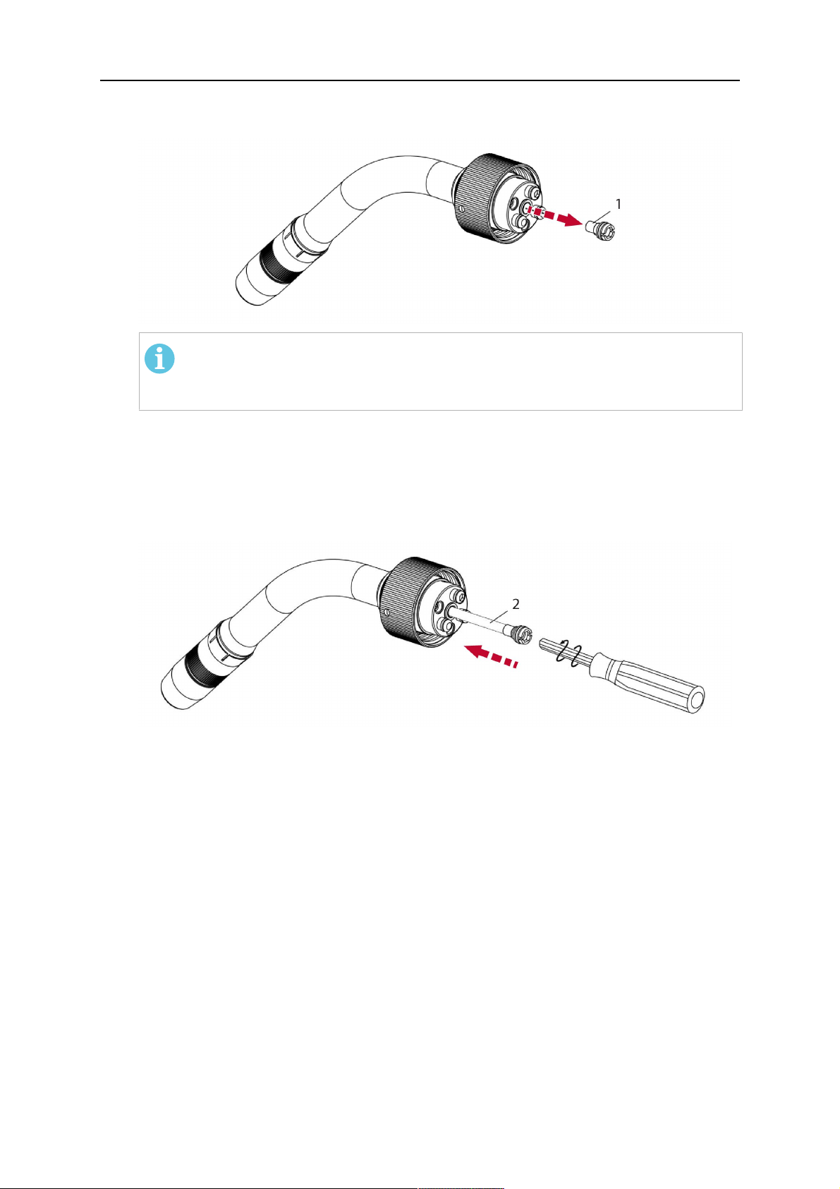
1. If present, remove the central guide nipple (1), from the torch neck using a hexagon
wrench (size 6 mm) or a large flat-blade screwdriver.
PASTABA!
The guide nipple (1) can only be used with one-piece liners and must not be
used with the standard RT or hollow wrist system.
2. When replacing the neck liner:
Unfasten the sleeve nut and remove the torch neck.
Unfasten the liner nipple using a hexagon wrench (size 6 mm) and remove nipple and
liner from the torch neck.
3. Remove the gas nozzle and the contact tip.
4. Insert the new neck liner (2) into the torch. Carefully tighten the guide nipple using a
suitable tool, e.g. a hex-wrench (size 6 mm) or a large flat-blade screwdriver.
5. Cut the neck liner flush with the tip holder and remove the neck liner from the torch.
6. Install the contact tip.
7. Insert the neck liner again. It will be stopped by the contact tip. Measure the excess
liner sticking out of the neck.
8. Remove the liner again and shorten the front end by the measured length. Carefully
deburr the edge and make sure that the inner hole is not blocked.
9. Reinstall the neck liner and tighten the guide nipple in the neck.
5.6.2 Installing a split wire guide in the cable assembly
The correct liner must be inserted to suit the filler material and the wire diameter, see the
spare parts list.
The wire guide is inserted through the cable assembly from the rear, reaching the guide
nipple that is installed in the flange where the torch neck will be attached. The following
worksteps must be followed in order to correctly determine the wire guide length. (Example
for Euro central connector).
0463 373 101
- 49 -
© ESAB AB 2018

5 INSTALLATION
1. For standard RT system: Install the guide nipple (1) in the center hole of the neck
support flange, see illustration A below.
For hollow wrist system: Install the guide nipple (1) into the torch interface of the
RTKSC-2 / RTFLC-2 cover, see illustration B below.
2. Remove the sleeve nut (2) from the central connector, and remove the old wire guide.
3. Insert the wire guide through the central connection and push forwards as far as it will
go into the guide nipple (1), applying light pressure.
DĖMESIO!
Ensure that the wire guide has advanced right up to the stop at the front,
rotating and pushing forward gently.
4. Measure the excess length that needs to be cut from the wire guide.
5. Remove the wire guide again and shorten the front end by the measured length.
Steel liner: grind down the burred edges if needed.
Plastic liner: make a clean cut and chamfer the edges (e.g. with a pencil sharpener)
PASTABA!
Make sure the inner opening of the liner is not obstructed by the cut wire end.
0463 373 101
- 50 -
© ESAB AB 2018

5 INSTALLATION
6. Reinstall the wire guide and attach the sleeve nut (2).
PASTABA!
For hollow wrist systems where Infiniturn and Helix cable assemblies are
used, wire guides should be installed without tension so that the ends of the
liners may rotate freely.
Important note when using a plastic liner:
The wire channel between the drive rolls of the feeder and the central
connector of the torch must be fitted with a plastic liner. Depending on the
design of the feeder, a piece of plastic liner inserted into a brass guide tube
can be used.
During wire run-in, make sure that the wire is fed correctly into the plastic liner
of the torch. If necessary, remove the cable assembly from the feeder and
insert the wire, then reattach.
5.6.3 Installing a continuous wire guide in the cable assembly
Installing a steel liner
The wire guide is inserted through the cable assembly from the rear and reaches to the
contact tip. The following worksteps must be followed for the correct calculation of the length
(example for Euro central connector):
1. Install the torch (see section "Torch neck equipment").
2. Remove the gas nozzle and contact tip from the torch.
3. Remove the sleeve nut (D) from the Euro connector.
4. Push in the liner through the central connector and fix with the sleeve nut.
5. Cut off the liner flush with the nozzle holder. To determine the thread projection of the
contact tip, pull the liner backwards and screw in the contact tip.
6. Push the liner forwards as far as it will go to the contact tip applying light pressure on
the liner and measure the length to be shortened at the rear.
7. Now remove the liner again and cut the excess length measured off it’s front end. If
needed, grind down the burred edges. Make sure the inner opening of the liner is not
obstructed by the cut wire end.
8. The insulation of the liner must be removed after cutting off in the front area, such that
the insulation protrudes out of the RM2 flange by approx. 5 cm. For this, briefly
remove the torch neck.
9. Push the liner back in again and fix with the sleeve nut (D), see above. Re-install the
gas nozzle.
0463 373 101
- 51 -
© ESAB AB 2018

5 INSTALLATION
Installing a plastic liner
1. Mount the torch neck (see section "Torch neck equipment") and equip it with a gas
nozzle and contact tip.
2. Remove the sleeve nut (D) from the Euro connector.
3. Cleanly cut off the liner, slightly break the outer edges, point slightly (e.g. with a pencil
sharpener).
4. Insert the liner through the central connector into the cable assembly with fitted torch.
If it gets stuck, rotate the liner to free it and facilitate installation.
PASTABA!
Make sure the liner is completely inserted by rotating it and slightly pushing it
forward, until you can feel it has reached its stop.
5. Mount the nipple (B) and the O-Ring (C), move it to the right position and fix it with the
sleeve nut (D) of the Euro central connector.
6. Measure the required overlap needed inside the wire feeder cabinet and cut the liner
accordingly.
5.7 Adjust the narrow gap contact tip
The adjusting tool RT42-NG is designed for the narrow gap torch necks RT42W-NG,
RT42G-NG and RT 82W-0°NG, torches with curved narrow gap contact tip. It facilitates the
precisely repeatable and fast changing of the curved contact tip.
PASTABA!
The adjusting tool must be securely fastened to a stable base, in order to prevent
the position of the device in relation to the robot cannot change unintentionally. If the
exact orientation of the device is lost, the alignment of the contact tip used for the
elaboration of the welding programs can no longer be reproduced with precision.
Select a position within the operating range of the robot for orientation (alignment) of the
contact tip to the torch. Fasten the adjusting tool firmly to a base using the fastening grooves
provided for this purpose. Fastening material is not included with the adjusting tool. Select
fastening material (screws) to suit the existing conditions.
Save all motion sequences and stop positions required to change or align the wearing parts
to a separate robot program.
Before programming the welding tasks: plan at which orientation the contact tip is to stand in
relation to the torch. The torch must then be positioned in the desired rotational position and
the contact tip aligned using the adjusting device. Only then may the welding task be
programmed. If different orientations of the contact tip are required for various welding tasks,
the contact tip has to be aligned to the new position when the welding task is changed.
ĮSPĖJIMAS!
The gas nozzle and the torch head become very hot during welding. Always allow
the torch to cool down before replacing wearing parts or adjusting the contact tip.
0463 373 101
- 52 -
© ESAB AB 2018
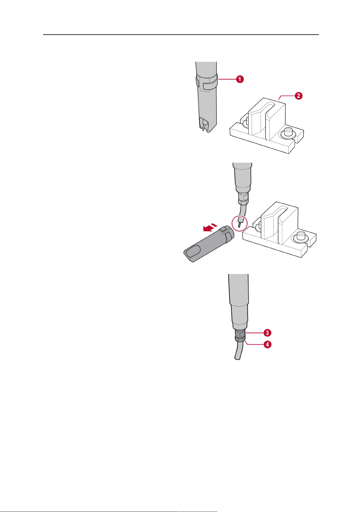
5 INSTALLATION
Adjust the contact tip
Move the robot torch to a position parallel to
the opening of the adjusting tool (2). Maintain
a sufficient distance to the work table to be
able to comfortably remove the gas nozzle.
Define this position in your robot program as
the wearing parts change position (stop
position 1).
Remove the gas nozzle by pulling it
downwards. Remove the welding wire in the
contact tip if necessary.
Loosen the counter nut (4) of the contact tip
while counter-holding the nozzle holder at the
wrench flat (3).
Unscrew the contact tip including the counter
nut from the nozzle holder and replace the
nozzle holder if necessary.
Completely screw the counter nut (4) onto the
new contact tip. Screw the contact tip
including the counter nut into the nozzle
holder.
Align the contact tip until it is parallel to the
opening of the adjusting tool. If necessary,
slightly unscrew the contact tip so that it can
be easily turned in both directions.
0463 373 101
- 53 -
© ESAB AB 2018

5 INSTALLATION
PASTABA!
The contact tip must be able to be
easily moved by hand in both
directions in order to enable the
threading of the adjusting tool.
Place the robot torch or contact tip directly in
front of the opening of the adjusting tool (2)
(stop position 2).
Insert it slowly from the front until it is
completely inserted into the device (stop
position 3).
The contact tip was aligned exactly in the
device during insertion. Now cautiously
tighten the counter nut (4) in this position,
while counter holding the nozzle holder at the
wrench flat.
Slowly move the robot torch out of the
adjusting gauge, return to stop position 1 and
push on the gas nozzle as far as it will go.
Allow the welding wire to run into the contact
tip and bring the robot arm into welding
position.
0463 373 101
- 54 -
© ESAB AB 2018

6 OPERATION
6 OPERATION
DĖMESIO!
Before starting the system, check the whole installation according to the
manufacturer's instructions and applicable safety regulations.
Check the following to make sure that the system has been installed correctly:
1. Are all parts securely attached (torch, torch mount, flanges, safety-off device, cable
assembly, and wire feeder cabinet)?
2. Are all media hoses connected correctly and protected from damage?
3. Is the EURO central connector or direct connector fastened tightly?
4. Is the cable assembly length correct and suitable for the installation and can the cable
rotate freely? The cable must not be bent sharply. Any risk of the cable getting caught
on another object must be eliminated.
5. Is the control cable of the safety-off circuit connected and functioning? Move torch by
hand to test (RTKSC-2 and RTKS-2 only).
6. Is the torch firmly attached and is it completely equipped?
7. Is the wire guide installed according to the manual?
8. Are all lines and tubes arranged so that they cannot be damaged or bent?
The wire run-in can now be started, either via the wire run-in pushbutton or via the wire run-in
at the feeder.
6.1 Important information for programming (hollow wrist system only)
Fast rotation of axis 6 of the robot will significantly stress the cable assembly. In certain
cases, this can lead to damage or destruction of the cable. In order to maximize the lifetime
of the cable, we strongly suggest respecting the following limitations when programming the
robot.
Position of axis 5 Max. rotational speed of axis 6
0 – 60° 100 % (no limitations)
60° – 80° 300°/sec (approximately 50 % of max. robot speed)
> 80° 120°/sec (approximately 20 % of max. robot speed)
PASTABA!
The above values are only indications. For information on the exact rotational speed
limits, refer to the individual robot manual or contact the robot supplier.
To reposition the torch quickly, the robot arm may have to be slightly extended first to achieve
a bending angle of max. 60° of axis 5. In this position, the maximum available rotation speed
of axis 6 can be used.
When using the ESAB Helix cable assembly, the max. rotation of ±270° from the neutral
position must not be exceeded.
0463 373 101
- 55 -
© ESAB AB 2018

6 OPERATION
DĖMESIO!
While axis 5 is bent more than 60°, the rotational speed of the torch around axis 6
must be limited, see table above.
Otherwise, the cable assembly may be damaged.
0463 373 101
- 56 -
© ESAB AB 2018

7 TECHNINĖ PRIEŽIŪRA
7 TECHNINĖ PRIEŽIŪRA
ĮSPĖJIMAS!
Prieš atliekant sistemos techninės priežiūros darbus, būtina atjungti energijos
tiekimą įrenginiui. Atkreipkite dėmesį į šio vadovo pradžioje pateiktus saugos
reikalavimus.
Negalima naudoti pažeistų degiklių arba kabelio įtaisų! Prieš naudojant įrangą,
žinomus defektus turi pašalinti kvalifikuoti specialistai.
ĮSPĖJIMAS!
Pavojus nudegti ir susižaloti! Dujų purkštukas ir degiklio galvutė suvirinimo metu gali
labai įkaisti. Prieš atlikdami techninės priežiūros darbus, palaukite, kol degiklis
atvės.
ĮSPĖJIMAS!
Tam, kad nesusižalotumėte ir nesugadintumėte įrangos, laikykitės šių nurodymų:
1. Remontuoti RTKSC-2 arba RTFLC-2 degiklio tvirtinimo detalę, RTKS-2
apsauginį mechanizmą, kabelio įtaisą arba „Infiniturn“ medžiagų tiekimo
jungtį gali remontuoti tik ESAB techninės priežiūros specialistai.
2. „Infiniturn“ medžiagų tiekimo jungties niekada negalima atidaryti. Joje nėra
jokių dalių, kurias galėtų remontuoti naudotojas, ir ji bus sugadinta
išmontuojant.
3. Niekada neišmontuokite RTKSC-2 arba RTKS-2. Tai yra spyruoklinis
mechanizmas. Netinkamai naudojant galima sunkiai susižaloti.
7.1 Privalomos patikros ir veiksmai
Kiekvieną kartą prieš naudodami:
• Patikrinkite degiklį, kontaktinį antgalį, dujų purkštuką, kaklelio įdėklą, kabelius ir visą
įrangą, ar nėra pažeidimų.
PASTABA!
Siekiant sumažinti galimų prastovų trukmę, rekomenduojama pakaitomis naudoti du
degiklio kaklelius ir visada netoliese turėti paruoštą degiklio kaklelį.
Kas 8 darbo valandas (atsižvelgiant į naudojimą):
• Pakeiskite kontaktinį antgalį.
Kasdien:
• Ranka patikrinkite apsauginio mechanizmo veikimą
• Apžiūrėkite, ar nėra pažeidimų, t. y. įlinkimų arba įskilimų.
• Patikrinkite, ar laido tiektuvo padėtis yra tinkama. Kabelio įtaisas neturi būti pernelyg
įtemptas arba nukaręs.
• Patikrinkite medžiagų tiekimo jungtis ir „Infiniturn“ medžiagų tiekimo jungtį, ar nėra
nuotėkio.
• Atlikite degiklio valymo ir techninės priežiūros darbus, kaip nurodyta degiklio vadove.
Kas 40 darbo valandų (atsižvelgiant į naudojimą):
• Pakeiskite vielos įdėklus.
• Pakeiskite kaklelio įdėklus.
0463 373 101
- 57 -
© ESAB AB 2018

7 TECHNINĖ PRIEŽIŪRA
Kas savaitę arba pagal poreikį, atsižvelgiant į naudojimą:
• Išimkite vielos kreiptuvą ir patikrinkite, ar jis nesusidėvėjo ir ar nėra susikaupusio purvo.
Jei reikia, pakeiskite.
Kas mėnesį arba dažniau, jei daug naudojama (t. y. daugiau nei 8 valandas per dieną):
• Prapūskite vielos kreiptuvo kanalą suslėgtu oru (išimkite kontaktinį antgalį ir vielos
kreiptuvą).
• Patikrinkite, ar visi varžtai yra priveržti.
• Patikrinkite, ar nepažeistos jungtys ir žarnos.
• Pakeiskite sunaudojus visus 250 kg suvirinimo vielos.
Tam, kad sistemą būtų galima naudoti saugiai, pažeistą elektrinę izoliaciją turi suremontuoti
parengti darbuotojai.
0463 373 101
- 58 -
© ESAB AB 2018

8 GEDIMŲ ŠALINIMAS
8 GEDIMŲ ŠALINIMAS
Triktis Galima priežastis Veiksmas
Netiekiama viela Suvirinimo viela prieš tiekiant į
kabelio įtaisą nebuvo ištiesinta.
Degiklis ir kabelio įtaisas nepritaikyti
prie naudojamos vielos skersmens
ir medžiagos
Vielos kreiptuvas netinkamai
įstatytas į kabelio įtaisą
Kontaktinį antgalį užblokavo
nuosėdos
Vielos kreiptuvas susidėvėjo
Vielos tiekimui trukdo degiklyje
esantis purvas ir nuosėdos
Degiklis per
daug įkaista
Kontaktinis antgalis arba antgalio
laikiklis netinkamai priveržtas
Jei reikia, vėl ištraukite suvirinimo
vielą, nupjaukite ir išlyginkite galą ir
ištiesinkite pirmuosius 10 cm vielos.
Tada vėl įkiškite į kabelio įtaisą.
Patikrinkite vielos kreiptuvą (kabelio
įtaisą ir degiklio kaklelį) ir kontaktinį
antgalį.
Šiek tiek ištraukite vielos kreiptuvą
iš „Euro“ jungties. Įstatydami vielos
kreiptuvą, turėtumėte jausti, kad
paskutiniai keli centimetrai patenka į
degiklio jungties kreiptuvo movą.
Priešingu atveju vielos kreiptuvas
gali būti per trumpas ir įstatytas ne
iki galo.
Pakeiskite kontaktinį antgalį ir (arba)
vielos kreiptuvą, suslėgtu oru
prapūskite degiklio kaklelį, vielos
kreiptuvo kanalą ir vielos kreiptuvą.
Naudokite tinkamą įrankį ir
priveržkite ranka.
Vielos tiekimo
problemos
Aušinimo sistema neveikia tinkamai Patikrinkite vandens srautą,
užpildymo lygį ir švarumą.
Aušinimo sistema netinkamai
prijungta
Patikrinkite jungtis (vandens
įleidimo ir grąžinimo).
Degiklio apkrova per didelė Vadovaukitės techniniais
duomenimis, jei reikia, rinkitės kitą
tipą.
Kabeliai sugedę Patikrinkite kabelius, vamzdžius ir
jungtis.
Kontaktinis galiukas susidėvėjęs Pakeiskite kontaktinį antgalį.
Įdėklas nusidėvėjęs / purvinas Patikrinkite įdėklą; prapūskite. Jei
reikia, pakeiskite.
Naudojamos eksploatacinės
Patikrinkite atsarginių dalių sąrašą.
medžiagos nėra tinkamos vielos
skersmeniui arba medžiagai
Vielos tiektuvas nėra tinkamai
nustatytas
Kabelio įtaisas sulenktas arba
ištiestas per mažu spinduliu
Patikrinkite vielos tiekimo ritinėlius,
kontaktinį slėgį ir ritės stabdį.
Patikrinkite kabelio įtaisą, ar jis nėra
pažeistas. Ar įdėklą galima lengvai
įdėti? Įdėkite, kaip nurodyta. Žr. dalį
„Kabelio įtaiso montavimas“.
0463 373 101
Viela užteršta Pasinaudokite valymo šluoste.
- 59 -
© ESAB AB 2018

8 GEDIMŲ ŠALINIMAS
Triktis Galima priežastis Veiksmas
Vielos tiekimas
Vielos ritė yra tuščia Patikrinkite ant ritės esančios
sustabdomas
suvirinimo metu
Blokuojama viela kabelio įtaise Patikrinkite vielos tiekimą (galbūt
Viela nudega iki kontaktinio antgalio
arba susidėvėjo kontaktinis antgalis
Suvirinimo
Suveikė apsauginis mechanizmas. Nustatykite susidūrimo taškus ir
procesas
nutrūksta
Poros siūlėje Dujų sūkurys, sukeltas prilimpančių
purslų
Degiklio dujų srautas per silpnas
arba labai stiprus
Sugedo dujų tiekimas Patikrinkite srautą ir ar nėra
suvirinimo vielos kiekį vielos
tiektuve.
vyksta per greitai), patikrinkite
kontaktinį antgalį, ar jis nėra
užterštas (užsikimšęs), jei reikia,
išvalykite arba pakeiskite kontaktinį
antgalį.
Pakeiskite kontaktinį antgalį.
juos pašalinkite. Patikrinkite
valdymo liniją, ar nėra nutrūkusios
jungties.
Nuvalykite degiklio galvutę,
naudokite dujų difuzorių / apsaugą
nuo purslų.
Matavimo įrankiu patikrinkite srautą.
nuotėkio.
Lankas
nestabilus
Viela arba ruošinys drėgnas arba
užterštas
Patikrinkite vielą ir ruošinį,
naudokite mažiau nuo purslų
apsaugančio skysčio arba kitokį
skystį.
Kontaktinis galiukas susidėvėjęs Pakeiskite kontaktinį antgalį.
Netinkami suvirinimo parametrai Patikrinkite suvirinimo įrangos
konfigūraciją.
Nepakanka elektrinių jungčių
grandinėje
Patikrinkite, ar gerai sujungtos visos
elektrinės jungtys (įskaitant
įžeminimo kabelį) tarp degiklio
maitinimo šaltinio arba ruošinio.
0463 373 101
- 60 -
© ESAB AB 2018

9 ATSARGINIŲ DALIŲ UŽSAKYMAS
9 ATSARGINIŲ DALIŲ UŽSAKYMAS
DĖMESIO!
Remontą ir elektros darbus turėtų atlikti ESAB įgaliotas techninės priežiūros
inžinierius. Naudokite tik originalias ESAB atsargines ir susidėvinčias dalis.
ESAB RT degikliai RTKS-2, RTFL-2, RT-KSC-2, RT-FLC-2, RT42, RT52, RT62, RT72,
RT82, RT42-NG ir RT82WNG yra suprojektuoti ir išbandyti pagal tarptautinių ir Europos
standartų IEC/EN 60974-7 reikalavimus. Priežiūros arba remonto darbus atlikęs priežiūros
skyrius privalo užtikrinti, kad gaminys vėl atitiktų nurodytą standartą.
Atsargines dalis galima užsakyti iš artimiausio ESAB platintojo, žr. esab.com. Užsakydami
detales, nurodykite gaminio tipą, serijos numerį, pavadinimą ir atsarginės detalės numerį
pagal atsarginių detalių sąrašą. Turint šią informaciją, lengviau išsiųsti ir tinkamai pristatyti
reikalingą detalę.
0463 373 101
- 61 -
© ESAB AB 2018

ESAB AB, Lindholmsallén 9, Box 8004, 402 77 Gothenburg, Sweden, Phone +46 (0) 31 50 90 00
http://manuals.esab.com
For contact information visit esab.com
 Loading...