


RT Robo Welding Torch System
RTKS-2, RTFL-2, KSC-2, FLC-2, RT42, RT52,
RT62, RT72, RT82, RT42-NG, RT82WNG
Bruksanvisning
0463 373 101 NO 20181227


INNHOLD
1
SIKKERHET................................................................................................. 5
1.1 Symbolforklaring.................................................................................... 5
1.2 Sikkerhetsregler ..................................................................................... 5
2
GARANTI ..................................................................................................... 8
2.1 Betingelser for tiltenkt bruk................................................................... 8
3
INNLEDNING ............................................................................................... 9
3.1 Oversikt over sveisebrennersystemet ................................................. 9
4
TEKNISKE DATA......................................................................................... 11
4.1 Sveisebrennerhals ................................................................................. 11
4.2 Spenningsverdi....................................................................................... 12
4.2.1 Kjølekretsgrenser ................................................................................. 12
4.3 Brennerfeste ........................................................................................... 13
4.3.1 Brennerfester for standard RT-system ................................................. 13
4.3.1.1 RTKS-2-sikkerhetsmekanisme......................................................... 14
4.3.1.2 RTFL-2 mellomliggende flens........................................................... 14
4.3.2 Brennerfester for hollow wrist-system .................................................. 14
4.3.2.1 RTKSC-2 G/W-brennerfeste med sikkerhetsmekanisme................. 16
4.3.2.2 RTFLC-2 G/W stivt brennerfeste...................................................... 17
4.4 Adapterflenser ........................................................................................ 18
4.5 Kabler ...................................................................................................... 18
4.5.1 Kabler for standard RT-system............................................................. 18
4.5.2 Kabler for hollow wrist-systemer .......................................................... 19
5
INSTALLATION............................................................................................ 21
5.1 RTKS-2 standard arm installation........................................................ 21
5.1.1 RTKS-2 safety-off mechanism............................................................. 21
5.1.1.1 Torch installation with adjustable mount............................................ 22
5.1.2 Standard arm cable assembly for KS-2 and FL-2 ................................ 24
5.1.3 RTKS-2 wire feeder connection........................................................... 25
5.1.4 RTKS-2 electrical connections ............................................................ 26
5.1.4.1 RTKS-2 safety-off mechanism connection ....................................... 26
5.1.5 RTKS-2 Torch installation.................................................................... 27
5.2 RTFL-2 standard arm installation ........................................................ 28
5.2.1 RTFL-2 rigid mount.............................................................................. 28
5.2.2 RTFL-2 torch installation ..................................................................... 30
5.3 RTKSC-2 hollow wrist system installation.......................................... 30
5.3.1 RTKSC-2 mount with safety off mechanism........................................ 30
5.3.2 Mounting the cable assembly............................................................... 31
5.3.2.1 RTKSC-2 feeder cabinet connections .............................................. 32
5.3.3 RTKSC-2 cable assembly ................................................................... 34
5.3.3.1 RTKSC-2 cable assembly installation .............................................. 34
5.3.3.2 RTKSC-2 electrical connections....................................................... 37
0463 373 101 © ESAB AB 2018

INNHOLD
5.3.4 RTKSC-2 torch installation .................................................................. 38
5.4 RTFLC-2 installation.............................................................................. 39
5.4.1 RTFLC-2 mount................................................................................... 39
5.4.2 RTFLC-2 wire feeder connection......................................................... 39
5.4.2.1 Feeding through the robot arm.......................................................... 39
5.4.2.2 RTFLC-2 feeder cabinet connections............................................... 40
5.4.3 RTFLC-2 cable assembly.................................................................... 42
5.4.3.1 RTFLC-2 cable assembly installation............................................... 42
5.4.4 RTFLC-2 electrical connections .......................................................... 45
5.4.4.1 RTFLC-2 hollow wrist system with Infiniturn cable assembly........... 45
5.4.4.2 RTFLC-2 hollow wrist system with Helix cable assembly................. 46
5.5 Torch installation.................................................................................... 46
5.5.1 Torch neck equipment .......................................................................... 46
5.5.2 Aristo RT torch neck installation........................................................... 47
5.6 Installing the wire guide for standard and hollow Wrist arm ............. 48
5.6.1 Installing the neck liner......................................................................... 48
5.6.2 Installing a split wire guide in the cable assembly................................ 49
5.6.3 Installing a continuous wire guide in the cable assembly..................... 51
5.7 Adjust the narrow gap contact tip ........................................................ 52
6
OPERATION ................................................................................................ 55
6.1 Important information for programming (hollow wrist system only) 55
7
SERVICE OG VEDLIKEHOLD .................................................................... 57
7.1 Obligatoriske kontroller og tiltak .......................................................... 57
8
FEILSØKING ............................................................................................... 59
9
BESTILLING AV RESERVEDELER ............................................................ 61
Vi forbeholder oss retten til å endre spesifikasjoner uten varsel.
0463 373 101 © ESAB AB 2018

1 SIKKERHET
1 SIKKERHET
1.1 Symbolforklaring
Som brukt i denne bruksanvisningen: Betyr Merk! Vær på vakt!
FARE!
Angir umiddelbare farer som, hvis de ikke unngås, vil medføre umiddelbar
alvorlig personskade eller tap av liv.
ADVARSEL!
Angir mulige farer som kan medføre personskade eller tap av liv.
FORSIKTIG!
Angir farer som kan medføre mindre personskade.
ADVARSEL!
Før bruk skal du lese og forstå bruksanvisningen samt
følge alle skilter, arbeidsgivers sikkerhetsrutiner og
sikkerhetsdatablader (SDS-er).
1.2 Sikkerhetsregler
Brukere av ESAB-utstyr har det endelige ansvaret for å sørge for at alle som arbeider med
eller i nærheten av utstyret, følger alle relevante sikkerhetsanvisninger. Sikkerhetsreglene
må oppfylle kravene som gjelder for denne type utstyr. Anbefalingene nedenfor må følges i
tillegg til standardforskrifter som gjelder på arbeidsplassen.
Alt arbeid må utføres av opplært personale som er fortrolige med bruken av utstyret. Feil
bruk av utstyret kan føre til farlige situasjoner, noe som kan forårsake personskader og
skade på utstyret.
1. Alle som bruker utstyret, må være kjent med følgende:
○ bruken
○ plasseringen av nødstoppene
○ hvordan det fungerer
○ relevante sikkerhetstiltak
○ sveising og skjæring og annen aktuell bruk av utstyret
2. Operatøren må sørge for at:
○ ingen uvedkommende befinner seg innenfor arbeidsområdet for utstyret når det
startes opp
○ ingen er ubeskyttet når lysbuen tennes eller man har begynt å arbeide med
utstyret
3. Arbeidsplassen må:
○ være egnet til formålet
○ være fri for trekk
0463 373 101
- 5 -
© ESAB AB 2018

1 SIKKERHET
4. Personlig verneutstyr:
○ Bruk alltid anbefalt personlig verneutstyr, slik som vernebriller, flammesikre klær,
vernehansker
○ Ikke ha på deg løstsittende klær, slik som skjerf, armbånd, ringer osv, som kan
hekte seg fast eller føre til forbrenninger
5. Generelle forholdsregler:
○ Kontroller at returkabelen er sikkert tilkoblet.
○ Arbeid på høyspenningsutstyr skal alltid utføres av en autorisert elektriker.
○ Egnet brannslokkingsutstyr må være tydelig merket og tilgjengelig i nærheten.
○ Smøring og vedlikehold må ikke utføres på utstyret når det er i bruk.
ADVARSEL!
Buesveising og -skjæring kan være farlig for deg selv og andre. Ta forholdsregler
ved sveising og skjæring.
ELEKTRISK STØT – kan være livsfarlig
• Monter og jord enheten i samsvar med bruksanvisningen.
• Ikke ta i strømførende deler eller elektroder med bare hender eller vått
verneutstyr.
• Isoler deg selv fra jord og arbeidet.
• Sørg for å ha en trygg arbeidsposisjon.
ELEKTRISITET OG MAGNETFELTER – kan være helsefarlige
• Sveisere med pacemaker bør rådføre seg med lege før sveising. EMF kan
forstyrre enkelte pacemakere.
• Eksponering for EMF kan ha andre, ukjente helseeffekter.
• Sveisere skal benytte følgende prosedyre for å minimere eksponeringen
for EMF:
○ Før elektrode- og arbeidskablene sammen på samme side av
kroppen. Sikre dem med tape der dette er mulig. Ikke plasser
kroppen din mellom brenneren og arbeidskablene. Du må aldri kveile
brenner- eller arbeidskabelen rundt kroppen din. Holdt
sveisestrømkilden og kablene så langt borte fra kroppen som mulig.
○ Koble arbeidskabelen til arbeidsemnet så nært området som sveises,
som mulig.
RØYK OG GASSER – kan være helsefarlige
• Vend ansiktet bort fra sveiserøyken.
• Bruk ventilasjon, avtrekk ved lysbuen eller begge deler for å lede røyk og
gasser bort fra pusteområdet og hele området.
STRÅLER FRA LYSBUEN - kan skade øynene og gi brannskader på huden
• Beskytt øynene og kroppen. Bruk riktig sveiseskjerm og filterlinse, og bruk
alltid verneklær.
• Beskytt omgivelsene rundt med egnede beskyttelsesskjermer eller
forheng.
0463 373 101
STØY – for sterk støy kan skade hørselen
Beskytt ørene. Bruk øreklokker eller annet hørselvern.
- 6 -
© ESAB AB 2018

1 SIKKERHET
BEVEGELIGE DELER – kan forårsake personskade
• Hold alle dører, paneler og deksler lukket og godt på plass. Bare kvalifisert
personell skal fjerne deksler for vedlikehold og feilsøking etter behov.
Monter paneler og deksler, og lukk dører, når servicearbeidet er fullført, og
før motoren startes.
• Stopp motoren før du monterer eller kobler til en enhet.
• Hold hender, hår, løstsittende klær og verktøy borte fra bevegelige deler.
BRANNFARE
• Gnister (sprut) kan forårsake brann. Sørg for at det ikke er noen brennbare
materialer i nærheten.
• Ikke bruk på lukkede beholdere.
FUNKSJONSFEIL – tilkall eksperthjelp ved funksjonsfeil.
BESKYTT DEG SELV OG ANDRE!
FORSIKTIG!
Dette produktet er bare beregnet til buesveising.
ADVARSEL!
Ikke bruk strømkilden til å tine frosne rør.
FORSIKTIG!
Klasse A-utstyr er ikke beregnet på bruk i boligområder
der strømmen leveres av den offentlige
lavspenningsstrømforsyningen. Det kan være vanskelig
å sikre elektromagnetisk kompatibilitet for klasse
A-utstyr i slike omgivelser på grunn av ledningsbårne
forstyrrelser og strålingsforstyrrelser.
OBS!
Lever elektronisk utstyr inn til et mottak for
gjenvinning!
I henhold til EU-direktivet 2012/19/EF om elektrisk og
elektronisk avfall og direktivets implementering i
samsvar med nasjonale lovregler, skal elektrisk og/eller
elektronisk utstyr etter endt levetid leveres inn til et
mottak for gjenvinning.
Som ansvarlig for utstyret er det ditt ansvar å skaffe til
veie informasjon om godkjente innsamlingsstasjoner.
Kontakt nærmeste ESAB-forhandler for mer
informasjon.
ESAB har et utvalg sveisetilbehør og personlig verneutstyr til salgs. Ta kontakt med
en lokal ESAB-forhandler eller gå til nettsiden vår for å finne bestillingsinformasjon.
0463 373 101
- 7 -
© ESAB AB 2018

2 GARANTI
2 GARANTI
Produktene våre kontrolleres nøye før levering. ESAB verifiserer at hvert enkelt produkt er
uten defekter i materiale og utførelse ved levering og fungerer i henhold til tiltenkt bruk.
ESAB gir garanti mot defekter i materiale og utførelse i henhold til juridiske krav.
Forbruksartikler er unntatt fra denne garantien.
Garantien dekker ikke eventuelle skader eller funksjonelle defekter som skyldes:
• overbelastning, misbruk eller avvik fra tiltenkt bruk av produktet
• kollisjoner eller ulykker
• manglende samsvar med instruksjoner angitt i disse brukerinstruksjonene
• feilaktig installasjon eller montering
• utilstrekkelig vedlikehold
• modifisering av produktet fra den opprinnelige tilstanden
• kjemisk påvirkning
• normal slitasje
ESAB påtar seg ikke ansvar for annet enn utskifting eller reparasjon av defekte deler.
2.1 Betingelser for tiltenkt bruk
1. Produktet er beregnet på industriell og kommersiell bruk og må bare brukes av
kvalifisert personell. Produsenten er ikke ansvarlig for skader eller ulykker som følge
av feil bruk.
2. Aristo® RT-robotsveisesystem er utformet og produsert med toppmoderne materialer
og metoder og er trygt og pålitelig i drift når det håndteres, monteres og vedlikeholdes
av kvalifisert personell. Instruksjonene for installasjon, drift og vedlikehold som er
beskrevet i dette dokumentet, må følges.
3. Aristo® RT-robotsveisesystemet må bare monteres, drives og vedlikeholdes av
kvalifisert personell. Installasjons-, drifts- og vedlikeholdsforskriftene som er beskrevet
i denne håndboken, må følges.
4. Aristo® RT-robotsveisesystemet må utelukkende brukes til det formålet det er tiltenkt
av produsenten, innenfor rammen av de tekniske dataene og med automatiserte
håndteringssystemer. Brennertypen må velges for å passe til sveiseoppgaven.
5. Aristo® RT-robotsveisesystemet ble utformet for å brukes som et komplett system.
Det er ikke tillatt å inkluder komponenter fra andre produsenter.
6. RT KS-2 og RT KSC-2 skal bare brukes som nødstoppmekanismer innenfor deres
tekniske spesifikasjoner og i kombinasjon med en standard RT-armkabel (KS-2),
Infiniturn eller Helix (KSC-2), ESAB-adapterflens, inkludert RT-brennerfester (KS-2) og
en Aristo RT-sveisebrenner.
7. Ingen olje eller antisprutvæske skal tilsettes utblåsningsgassen. ESAB garanterer ikke
kjemisk resistens mot disse stoffene. ESAB anbefaler å bruke ESAB-sprayenheten for
å påføre minimumsmengden med antisprutvæske på brenneren og derfor beskytte
miljøet.
8. Produktet må holdes tørt og beskyttes mot fuktighet når det transporteres, lagres eller
brukes.
9. Systemet er konstruert for omgivelsestemperaturer fra 5 til 40°C. Hvis disse grensene
overskrides, kreves det spesifikke tiltak. Bruk en egnet kjølevæske ved fare for frost.
0463 373 101
- 8 -
© ESAB AB 2018

3 INNLEDNING
3 INNLEDNING
RT-sveisebrennersystemene er utviklet for helautomatisk MIG-/MAG-sveising med roboter.
Systemene består av en rekke Aristo RT-brennerhalser som er designet for robotbruk,
brennerfester, kabler som er optimalisert for robotbruk, og sikkerhetsfunksjoner for å
forhindre skade på systemet i tilfelle kollisjoner.
Det standard RT-sveisesystemet gir kollisjonsbeskyttelse ved bruk av RT KS-2, som er en
mekanisk fjærbelastet sikkerhetsfunksjon. Dette kan eventuelt erstattes av RTFL-2 for å dra
fordel av robotstyresystemets kollisjonsdetekteringsfunksjon. Det standard
RT-sveisesystemet kan brukes med en rekke kabeltyper.
RTKSC-2 og RTFLC-2 brennerfester med Infiniturn- eller Helix-kabler er beregnet for bruk i
robotsveisehollow wrist-systemer for avanserte sveiseoppgaver. Sikkerhetsmekanismen i
RTKSC-2-brennerfestet muliggjør stor elastisk avbøyning av brenneren i tilfelle kollisjon.
Infiniturn- og Helix-kabelene er enkle å montere og gir et svært pålitelig system med presise
manøvreringsegenskaper.
I kombinasjon med veletablerte Aristo RT-robotsveisebrennere skaper disse bestanddelene
et svært pålitelig og langvarig system som bare trenger et minimum av vedlikehold.
Bruksanvisningen er inkludert ved levering av brennerfester og kabler.
ESAB-ordrenumre, tilgjengelig tilbehør, reservedeler og slitasjedeler finnes i
reservedelslisten.
3.1 Oversikt over sveisebrennersystemet
Standard RT-system
For en detaljert beskrivelse kan du se den
tilsvarende delen i kapittelet TEKNISKE
DATA:
1. Brennerhals
Se Sveisebrenner.
2. Kabel
Se Kabler for standard RT-system.
3. Brennerfeste
Se Brennerfester for standard
RT-system.
4. RTKS-2-sikkerhetsmekanisme
Se RTKS-2-sikkerhetsmekanisme.
5. RTFL-2 mellomliggende flens
Se RTFL-2 mellomliggende flens.
6. Adapterflens (hvis nødvendig)
Se Adapterflenser.
0463 373 101
- 9 -
© ESAB AB 2018

3 INNLEDNING
Hollow wrist-system
For en detaljert beskrivelse kan du se den
tilsvarende delen i kapittelet TEKNISKE
DATA:
1. Brennerhals
Se Sveisebrenner.
2. Brennerfeste RTKSC-2
Se RTKSC-2-brenner feste med
sikkerhetsmekanisme.
3. Brennerfeste RTFLC-2
Se RTFLC-2 stivt brennerfeste.
4. Adapterflens
Se Adapterflenser.
5. Helix- eller Infiniturn-kabel
Se Kabler for hollow wrist-systemer.
0463 373 101
- 10 -
© ESAB AB 2018

4 TEKNISKE DATA
4 TEKNISKE DATA
4.1 Sveisebrennerhals
Velg brennermodellen i henhold til sveiseoppgaven. Den nødvendige driftssyklusen og
kapasiteten, kjølemetoden og tråddiameteren må tas i betraktning. Hvis det er økte krav, for
eksempel forårsaket av forvarmede arbeidsstykker eller høy varmerefleksjon i hjørner, må
disse tas hensyn til ved å velge en sveisebrenner med tilstrekkelig reserve i nominell effekt.
RT-sveisebrennerne er beregnet på bruk med CE-kompatible sveisestrømkilder for
prosessene gassmetallbuesveising med inert beskyttelsesgass (MIG),
gassmetallbuesveising med aktiv beskyttelsesgass (MAG) og MIG-lodding med
kommersielle rundtråder. Ikke bruk brenneren til andre prosesser.
For pulserende buesveising av stål eller aluminiumssveising må RT 82W vannkjølt brenner
brukes.
Se tilgjengelige brennermodeller under.
Brennermodell Kjølemetode Dekkgass Klassifisering
RT42G Gasskjølt CO
Gasskjølt 300A/ 100%
Gasskjølt Blanding 350A/ 60%
Gasskjølt 250A/ 100%
RT42W Vannkjølt CO
Vannkjølt 420A/ 100%
Vannkjølt Blanding 350A/ 60%
Vannkjølt 350A/ 100%
RT52G Gasskjølt CO
Gasskjølt 300A/ 100%
Gasskjølt Blanding 350A/ 60%
Gasskjølt 250A/ 100%
RT52W Vannkjølt CO
Vannkjølt 470A/ 100%
Vannkjølt Blanding 400A/ 60%
Vannkjølt 400A/ 100%
RT62G Gasskjølt CO
Gasskjølt 340A/ 100%
2
2
2
2
2
420A/ 60%
420A/ 60%
420A/ 60%
470A/ 60%
500A/ 60%
Gasskjølt Blanding 420A/ 60%
Gasskjølt 290A/ 100%
RT62W Vannkjølt CO
Vannkjølt 530A/ 100%
Vannkjølt Blanding 450A/ 60%
Vannkjølt 450A/ 100%
0463 373 101
- 11 -
2
530A/ 60%
© ESAB AB 2018

4 TEKNISKE DATA
Brennermodell Kjølemetode Dekkgass Klassifisering
RT72G Gasskjølt CO
2
480A/ 60%
Gasskjølt 320A/ 100%
Gasskjølt Blanding 400A/ 60%
Gasskjølt 270A/ 100%
RT72W Vannkjølt CO
2
480A/ 60%
Vannkjølt 430A/ 100%
Vannkjølt Blanding 480A/ 60%
Vannkjølt 430A/ 100%
RT82W Vannkjølt CO
2
600A/ 60%
Vannkjølt 600A/ 100%
Vannkjølt Blanding 550A/ 60%
Vannkjølt 550A/ 100%
Verdiene for brennerytelse og arbeidssyklus er gyldige i en 10-minutters syklus.
De tekniske dataene er gyldige for et standardisert bruksområde som bruker standard
slitasjedeler/reservedeler. Brennerytelsen reduseres når du bruker metalloverføringsmodus
med pulserende bue.
Temperaturområder Oppbevaring: –15–50°C (5–122°F)
Betjening: 5–40°C (41–104°F)
Utblåsningsgass Maks. 10bar, separat gasslange
Total vekt (brennerhals,
Ca. 5kg
sikkerhetsmekanisme, brennerfeste og 1m
kabel)
4.2 Spenningsverdi
Maks. tillatt spenning/strømstyrke
Komplett sveisebrennersystem 141V (toppverdi for sveising)
RTKS-2 sikkerhetskontrollkrets
RTKS-2 trykknapp
RTKSC-2 sikkerhetskontrollkrets 48V
Bruker dysesensorfunksjonalitet med en
standard kabel
Bruker dysesensorfunksjonalitet med Helixeller Infiniturn-kabler
24V/ 1A
48V/ 0,1A
50V/ 5A
(Tillatt belastning maks. 1 minutt ved nominell
strøm)
50V/ 5A
(Tillatt belastning maks. 1 minutt ved nominell
strøm)
Den angitte ytelsen viser til en standardisert bruk.
For kabelklassifisering kan du se avsnittet Kabler.
4.2.1 Kjølekretsgrenser
Gjelder kun for vannkjølt versjon.
0463 373 101
- 12 -
© ESAB AB 2018

4 TEKNISKE DATA
Min. vanngjennomstrømning: 1,0l/min
Min. vanntrykk: 2,5bar
Maks vanntrykk: 3,5bar
Inntakstemperatur: Maks 40°C
Tilbakeløpstemperatur: Maks 60°C
Kjølekapasitet: Min. 1000W, avhengig av bruksområde
FORSIKTIG!
Tilbakeløpstemperaturer på over 60°C kan føre til skade eller ødelegge kabelen.
4.3 Brennerfeste
Typen brennerfeste som kreves avhenger av utformingen av RT-sveisebrennersystemet og
valg av sikkerhetsutstyr. Se avsnittet Oversikt over sveisebrennersystemer.
Komponent Omtrentlig vekt
Brennerfeste (for standardsystem) 0,43 kg
RTKS-2-sikkerhetsmekanisme (for
0,85 kg
standardsystem)
RTFL-2 mellomliggende flens (for
0,35 kg
standardsystem)
RTKSC-2-brennerfeste (for hollow
1,90 kg
wrist-system)
RTFLC-2 stivt brennerfeste (for hollow
1,22 kg
wrist-system)
Robotsveisebrenner 0,66 kg
4.3.1 Brennerfester for standard RT-system
For standard RT-systemer er brennerfestet montert på RTKS-2-sikkerhetsmekanismen
(alternativt på RTFL-2 mellomliggende flens), som klemmer kabelen og den tilkoblede
brennerhalsen.
Velg brennerfestet i henhold til brennertypen og dens geometri. Ulike festetyper kan brukes.
Se reservedelslisten over tilgjengelige brennerfester for standard RT-system.
Brennerfeste for roboter med standardarm
0463 373 101
- 13 -
© ESAB AB 2018

4 TEKNISKE DATA
4.3.1.1 RTKS-2-sikkerhetsmekanisme
RT KS-2-sikkerhetsmekanismen er en fjærstøttet enhet som beskytter roboten og
brennersystemet i tilfelle kollisjon.
OBS!
Ikke demonter RTKS-2.
4.3.1.2 RTFL-2 mellomliggende flens
Den stive mellomliggende flensen RTFL-2 kan brukes i stedet for RTKS-2 hvis roboten har
et elektronisk kollisjonsdetekteringssystem.
4.3.2 Brennerfester for hollow wrist-system
I hollow wrist-system er Aristo RT-sveisebrennerhalsene koblet til brennerfestet KSC-2 eller
FLC-2.
Brennerfestet RT KSC-2 muliggjør elastisk avbøyning av brenneren i tilfelle kollisjon.
Samtidig åpnes en elektrisk kontakt som signaliserer at robotstyringen skal stoppe. Etter
tilbakestilling av feilen vil den første geometrien og verktøysenterpunktet (TCP) til brenneren
nås med høy presisjon. Systemet fungerer rent mekanisk og er fjærbelastet.
Brennerfestet RTFLC-2 har ingen innebygd sikkerhetsfunksjon.
0463 373 101
- 14 -
© ESAB AB 2018

4 TEKNISKE DATA
For hollow wrist-system anbefales RTKSC-2 G/W (alternativt RTFLC-2 G/W). Dette
brennerfestet kan brukes med både gasskjølte og vannkjølte brennere i Aristo RT-serien.
RTKSC-2 G/W RTFLC-2 G/W
Funksjonelt prinsipp for
Mekanisk Ikke aktuelt (stivt feste)
sikkerhetsmekanismen
Aksial frigjøringskraft (Fz) 650 N Ikke aktuelt (stivt feste)
Frigjør dreiemoment på
24Nm Ikke aktuelt (stivt feste)
tverrgående akse (Mx)
Tilbakestill etter frigjøring Automatisk Ikke aktuelt (stivt feste)
Repeterbarhet Lateral ±0,1mm ved TCP til
Ikke aktuelt (stivt feste)
en standard Aristo
RT-brenner
Maks. avbøyning Omtrent ±8° Ikke aktuelt (stivt feste)
Sikkerhetsbryter Normalt lukket
Ikke aktuelt (stivt feste)
Elektrisk belastning maks.
48V / 1A
0463 373 101
- 15 -
© ESAB AB 2018

4 TEKNISKE DATA
Elektrisk kontrollkrets for
dysesensorfunksjonalitet
Klassifisering:
• For Helix-kabler: maks
50VDC/ 5A, maks.
1minutt
Koble fra
sensorspenningen raskt
etter registrering av
kontakt.
• For Infiniturn-kabler har
dysesensorfunksjonen
Klassifisering:
• For Helix-kabler: maks
50VDC/ 5A, maks.
1minutt
• For Infiniturn-kabler:
maks 50VDC / 1 A,
maks. 1minutt
Koble fra sensorspenningen
raskt etter registrering av
kontakt.
begrenset funksjon.
Kontakt ESAB for en
detaljert undersøkelse
av mulige løsninger for
bruksområdet ditt.
Spenningsverdi Maksimal tillatt spenning for
sikkerhetskontrollkretsen:
48V.
4.3.2.1 RTKSC-2 G/W-brennerfeste med sikkerhetsmekanisme
PunktBeskrivelse Funksjon
1 Brennerhalsstøtte Aristo RT-brennerberøringspunkt
2 RTKSC-2-deksel Modul med kabel og brennerberøringspunkt
3 Gummikappe Beskyttelse for sikkerhetsmekanisme
0463 373 101
- 16 -
© ESAB AB 2018

4 TEKNISKE DATA
PunktBeskrivelse Funksjon
4 RTKSC-2-hoveddel Gjør det mulig med mekanisk avbøyning under en
kollisjon
5 Adapterflens Isolasjonsmodul til robothåndledd (må passe til den
spesifikke roboten)
6 Registerpinne For nøyaktig justering etter adapterflensen
7 Tilkobling for kontrollkabel Elektrisk tilkobling for kollisjonssignal og
dysesensorfunksjonalitet
8 Mikrobryter Sensor for kollisjonsdetektering
4.3.2.2 RTFLC-2 G/W stivt brennerfeste
PunktBeskrivelse Funksjon
1 Brennerhalsstøtte Aristo RT-brennerberøringspunkt
2 RTFLC-2-deksel Modul med kabel og brennerberøringspunkt
3 RTFLC-2-hoveddel Gjør det mulig med mekanisk avbøyning under en
kollisjon
4 Registerpinne For nøyaktig justering etter adapterflensen
5 Adapterflens Isolasjonsmodul til robothåndledd (må passe til den
spesifikke roboten)
6 Tilkobling for kontrollkabel
(3-polet)
0463 373 101
Elektrisk tilkobling for dysesensorfunksjonalitet (hvis
aktuelt)
- 17 -
© ESAB AB 2018

4 TEKNISKE DATA
4.4 Adapterflenser
Velg adapterflensen som er nødvendig for installasjon på robotarmen avhengig av
robottypen. Adapterflenser for alle passende standardsystemer og hollow wrist-systemer er
tilgjengelige. Se reservedelslisten.
4.5 Kabler
Tilkoblingen til trådmatingen påvirkes av kabelen. De tilgjengelige versjonene avhenger
hovedsakelig av systemdesign og kjølemedier (gass eller vann). Se reservedelslisten.
Klassifiseringene er gyldige for kabellengder fra 1 til 5 m.
Standard kabel Infiniturn Helix
Klassifisering (10min
syklus)
Gasskjølt (blandet
gass)
Klassifisering (10min
syklus)
Maks. 500A/ 60%
arbeidssyklus
Maks. 350A/ 100%
arbeidssyklus
Maks. 600A/ 100%
arbeidssyklus
Maks. 400A/ 60%
arbeidssyklus
Maks. 320A/ 100%
arbeidssyklus
Maks. 550A/ 100%
arbeidssyklus
Maks. 400A/ 60%
arbeidssyklus
Maks. 320A/ 100%
arbeidssyklus
Maks. 550A/ 100%
arbeidssyklus
Vannkjølt
Rotasjonsområde Begrenset roterbarhet Uendelig roterbar ±270° fra nøytral
posisjon
Vekt
Gasskjølt
Vekt
Vannkjølt
1,2m lang:
2,35 kg
1,2m lang:
2,35 kg
1,0m lang:
2,0 kg
1,0m lang:
2,0 kg
1,0m lang:
2,0 kg
1,0m lang:
2,0 kg
4.5.1 Kabler for standard RT-system
Burndy-kontaktpinner
A. Touch sense-gassdyse
C. Kollisjonssensor
D. Kollisjonssensor
E. Justering
0463 373 101
F. 0V
G. motorspenning +
G. motorspenning –
- 18 -
© ESAB AB 2018

4 TEKNISKE DATA
PunktBeskrivelse Funksjon
1 Halsfesteflens Brennerberøringspunkt
2 Beskyttelsesdeksel Beskytter kabelen fra skade
3 Burndy-kontakt, 12-polet Elektrisk tilkobling mellom sikkerhetsutkobling og
trådmater
4 Styreledning For KS-2 (sikkerhetsmekaniske og trykknapp)
5 EURO-kontakt Trådmatertilkobling
6 Blåseslange (sort hette) For rengjøring av brenneren med trykkluft etter
rengjøring
7 Vanninntak (blå hette)
8 Vanntilbakeløp (rød hette)
Vanninntak for brennerkjøling
Vanntilbakeløp av oppvarmet vann fra brenneren
1)
1)
9 Kontrollkabelplugg for
sikkerhetsmekanisme
Elektrisk tilkobling med RTKS-2 for
sikkerhetsutkoblingssignal og
dysesensorfunksjonalitet
1)
Bare for vannkjølte brennersystemer
4.5.2 Kabler for hollow wrist-systemer
Infiniturn-kabel tillater uendelig rotasjon av brenneren i begge retninger. Samtidig overføres
kjølevæske, beskyttelsesgass, utblåsingsluft, sveisekraften og signalet fra
sikkerhetsmekanismen.
Helix-kabelen er utformet for et rotasjonsområde på ±270° fra nøytral posisjon. Den kan
brukes til sveiseoppgaver som ikke krever uendelig rotasjon.
Infiniturn-kabler er tilgjengelige i gass- og vannkjølte versjoner. Helix-kabler kan brukes
universelt til gass- eller vannkjølte bruksområder.
OBS!
Ikke koble en Helix-kabel som drives av en gasskjølt brennerhals til et
vannkjølingssystem.
0463 373 101
- 19 -
© ESAB AB 2018

4 TEKNISKE DATA
PunktBeskrivelse Funksjon
1 Flens Brennerfeste RTKSC-2 / RTFLC-2-berøringspunkt
2 Registerpinne Sikrer riktig koblingsretning
3 Kontrollkabelplugg Elektrisk tilkobling til RTKSC-2 for
sikkerhetsutkoblingssignal og
dysesensorfunksjonalitet (hvis aktuelt)
4 EURO-kontakt Trådmatertilkobling
5 Styreledning Elektrisk tilkobling for sikkerhetsutkoblingssignal (fra
RTKSC-2) og dysesensorfunksjonalitet (dysesensor
er standard for Helix, ikke for Infiniturn)
6 Vanntilbakeløp (rød hette) Vanntilbakeløp av oppvarmet vann fra brenneren
7 Vanninntak (blå hette) Vanninntak for brennerkjøling
8 Blåseslange (sort hette) For rengjøring av brenneren med trykkluft etter
sveising
9 Mediakobling Uendelig roterbar kobling med mediaoverføring
10 Beskyttelsesdeksel Beskytter kabelen fra skade
0463 373 101
- 20 -
© ESAB AB 2018

5 INSTALLATION
5 INSTALLATION
ADVARSEL!
For your own safety, make sure that the robot is either in standby or power-less
state before doing maintenance work in the moving radius of the robot.
Follow the assembly instructions exactly. Pay attention during assembly that the cables are
not damaged. Damaged cables can lead to a short circuit, which may damage the electronics
of the robot or the welding torch.
Use only original ESAB components that have been specially developed for this purpose.
Only then the correct functioning of the whole welding torch system can be guaranteed.
5.1 RTKS-2 standard arm installation
5.1.1 RTKS-2 safety-off mechanism
1. Dismount the insulation flange (10) from the RTKS-2 (11) by removing the screws
(12).
2. Position the insulation flange (10) with the index pin on the robot arm and fix it with the
screws (20) included.
The insulation flange (10) is directly compatible with robots with tool flange according
to DIN ISO 9409-1-A40 (diameter 40mm, 4×M6). If the insulation flange (10) does
not fit, use an adapter flange (21).
OBS!
Ensure that the index pin is located correctly. The maximum torque of 1.2Nm
(10.5in.lb) must be observed for the fastening of the adapter flange screws.
Prevent self-loosening of the screws by using suitable thread locking
measures.
3. Mount the RTKS-2 the back on the insulation flange (10).
0463 373 101
- 21 -
© ESAB AB 2018

5 INSTALLATION
4. Position the mount on the RTKS-2 and carefully insert the cylindrical pins (14) into the
holes provided. Take the position of the torch into account. Two mounting positions
may be potentially possible.
5. Screw the mount evenly using the enclosed cylinder screws with hexagon socket (12).
OBS!
The maximum tightening torque for the cylinder screw (5) is 6Nm (53in.lb)
and the property class category is 8.8.
12 - Cylinder screw with hexagon socket
M6DIN912 (length of the screw depending
on the torch mount)
14 - Cylindrical pins Ø4×20
5.1.1.1 Torch installation with adjustable mount
Torch mounts with a central clamping assembly can only be fastened on the journal of the
mounting flange. For this, the mounting flange must be fastened first.
1. If applicable, carefully press the cylindrical pins (1) into the corresponding holes in the
mounting flange. The pins should protrude by approximately 5 mm (0.2 in.).
2. Position the mount on the safety-off mechanism RTKS-2 and carefully insert the
cylindrical pins (1) into the holes provided. In doing so, take the later position of the
torch into account. Two mounting positions may be potentially possible.
3. Then screw down the mounting flange evenly using the enclosed cylinder screws with
hexagon socket (2).
OBS!
The maximum tightening torque for the cylinder screw (2) is 7.1 Nm (62.8
in.lb) and the property class category is 8.8.
0463 373 101
- 22 -
© ESAB AB 2018

5 INSTALLATION
4. Unscrew the axial cylinder screw with hexagon socket (4) out of the mounting flange
together with the washer (3).
1 - Cylindrical pins Ø4×14 3 - Washer Ø9 mm
2 - Cylinder screw with hexagon socket
M6×16
4 - Axial cylinder screw with hexagon
socket M8×16
5. Place the torch mount (5) onto the journal (6) of the mounting flange, paying attention
while doing so to the exact alignment of the feather key (7) and the corresponding
groove (7a).
6. Insert the clamping mandrel (8) into the lateral hole (see illustration) and position it so
that the mating surfaces (9a) of the clamping mandrel rest on the mating surface (9) of
the journal.
0463 373 101
- 23 -
© ESAB AB 2018

5 INSTALLATION
7. Fix the clamping mandrel from the opposite side using the M6 cylinder screw with
hexagon socket (10) and the Ø22 mm washer (11).
8. Screw the axial cylinder screw (4) with the Ø9 mm washer (3) into the mounting flange
and tighten firmly.
3 - Washer Ø9 mm 8 - Clamping mandrel
4 - Axial cylinder screw with hexagon
9 - Mating surface of mounting flange
socket M8×16
5 - Torch mount 9a - Mating surfaces of clamping mandrel
6 - Mounting flange journal 10 - Cylinder screw with hexagon socket
M6×30
7 Feather key 11 - Washer Ø22×6.4 mm
7a - Groove for feather key
5.1.2 Standard arm cable assembly for KS-2 and FL-2
The cable assembly must be aligned to the intended use in length and design. The type of
cooling for the torch and the cable assembly must be the same (either gas or water cooled
respectively). In order to prevent damage to the torch system and other components, it is
imperative to observe the following instructions.
0463 373 101
- 24 -
© ESAB AB 2018

5 INSTALLATION
FORSIKTIG!
• Coordinate the length and design of the cable assembly to suit the range of
action of the robot.
• Do not bend, compress or overstretch the cable assembly.
• Fix the cable assembly such that is can be moved freely and cannot become
entangled.
• Any additional holding devices possibly installed, for example a balancer,
must not crush or bend the cable assembly.
• Extreme turning movements must be avoided in which the cable assembly
may become twisted.
• Chafing on the robot or other objects must be excluded.
1. Unscrew the cylinder screws (1) and lift off the top section (2) of the torch mount.
2. Insert the feather key (4) into the recess of the neck support flange (3) from below.
3. Align the neck support flange (3) including the feather key (4) to the groove (5) of the
torch mount and push into the groove right up to the stop of the flange.
4. Hold the cable assembly in this position and simultaneously place the top section (2)
back onto the torch mount. First screw both cylinder screws (1) loosely in to about the
same length, then tighten alternately. The top section (2) of the mount should have an
even gap to the bottom section.
The front part of the cable assembly is directly clamped into the torch mount (see
illustration below).
1 - Cylinder screws 4 - Feather key
2 - Torch mount top section 5 - Groove for feather key
3 - Neck support flange
5.1.3 RTKS-2 wire feeder connection
In order to be able to create the connection, the cable assembly must be mounted as
described in the "Installing the cable assembly" section and equipped following "Installing the
wire guide" section. Only then can the central and media connection take place. Proceed as
described below:
0463 373 101
- 25 -
© ESAB AB 2018

5 INSTALLATION
1. Connect the central connector of the cable assembly (2) to the wire feeder cabinet
socket. Tighten the central connector sleeve nut fingertight. Do not use tools.
1 - Burndy Connector 4 - Return of heated water (red cap)
2 - EURO central connector 5 - Return of heated water (red cap)
3 - Air blow-out 6 - Main Wire feeder
2. For water cooled systems. Connect the water hoses to the cooling circuit. The end of
the hose marked blue (4) is connected to the water outlet, and the end marked red (5)
is connected to the water return.
3. Connect the blow-out line (3) to the corresponding connection of the feeder.
4. Connect the Burndy Connector to the wire feeder. (1) to the feeder. See section
"Electrical connections".
OBS!
All hoses and the control line must be installed so they can not bend or get
damaged!
5.1.4 RTKS-2 electrical connections
5.1.4.1 RTKS-2 safety-off mechanism connection
The switch for the safety-off functionality RTKS-2 is connected through the control cable,
see (3) in the illustration below. This connects to the RTKS-2 unit via the 4-pole plug (4) that
contains circuits for the push-button (6) and the safety-off signal (7).
If a collision is detected, the control circuit for the safety-off signal (7), which is normally
closed, will be interrupted.
Rating of the control circuit: max. 48 V / 1 A
0463 373 101
- 26 -
© ESAB AB 2018

5 INSTALLATION
2 - Burndy connector 5 - RTKS-2 connector for control cable plug
4 - Control cable plug
Burndy-kontaktpinner
A. Touch sense-gassdyse
C. Kollisjonssensor
D. Kollisjonssensor
F. 0V
G. motorspenning +
G. motorspenning –
E. Justering
If the robot control provides a control circuit for nozzle sense functionality, the connection is
accomplished with a 1-wire connection.
Rating of the control circuit: max 50 V / 5 A.
FARE!
If the nozzle sense function is not being used, the open end of the control cable on
the power source connection side must be properly isolated in order to avoid short
circuits. During certain problems on the torch head, the full welding potential may be
present on this cable.
FORSIKTIG!
After detection of contact (gas nozzle on work piece), quickly reduce or cut off the
maximum current in the nozzle sense circuit in order to avoid overloading of the
system.
Allowed load max. 1 minute at the rated nominal current.
5.1.5 RTKS-2 Torch installation
Continue according to section "Torch installation".
0463 373 101
- 27 -
© ESAB AB 2018

5 INSTALLATION
5.2 RTFL-2 standard arm installation
5.2.1 RTFL-2 rigid mount
1. Position the RT FL-2 (2) with the index pin on the robot arm and fix it with the hexagon
socket screw included.
The FL-2 is directly compatible with robots with tool flange according to DIN ISO
9409-1-A40 (diameter 40mm, 4×M6). If the rigid mount does not fit, use an adapter
flange (3).
OBS!
Ensure that the index pin is located correctly. The maximum torque of 1.2Nm
(10.5in.lb) must be observed for the fastening of the adapter flange screws.
Prevent self-loosening of the screws by using suitable thread locking
measures.
2. Install torch mount (1). Only torch mounts having a hole pattern equivalent with the
mounting surface may be attached. If necessary, carefully press the cylindrical pins (4)
into the corresponding holes in the bracket. The pins should protrude by
approximately 5mm (0.2in.). Position the torch mount on the RTFL-2 (2) and
carefully insert the cylindrical pins (4) into the holes provided. Take the position of the
torch into account. Two mounting positions may be potentially possible.
3. Screw the mount evenly using the enclosed cylinder screws with hexagon socket (5).
OBS!
The maximum tightening torque for the cylinder screw (5) is 6Nm (53in.lb)
and the property class category is 8.8.
0463 373 101
- 28 -
© ESAB AB 2018
5 INSTALLATION
4 - Cylindrical pins Ø4×20
5 - Cylinder screw with hexagon socket M6
DIN 912 (length of the screw depending on
the torch mount)
Side view
Torch installation with adjustable mount
Torch mounts with a central clamping assembly can only be fastened on the journal of the
mounting flange. For this, the mounting flange must be fastened first.
1. If applicable, carefully press the cylindrical pins (1) into the corresponding holes in the
mounting flange. Avoid the formation of burrs. The pins should protrude by
approximately 5 mm (0.2 in.).
2. Position the mount on the RTFL-2 and carefully insert the cylindrical pins (1) into the
holes provided. In doing so, take the later position of the torch into account. Two
mounting positions may be potentially possible.
3. Then screw down the mounting flange evenly using the enclosed cylinder screws with
hexagon socket (2).
OBS!
The maximum tightening torque for the cylinder screw (2) is 7.1 Nm (62.8
in.lb) and the property class category is 8.8.
4. Unscrew the axial cylinder screw with hexagon socket (4) out of the mounting flange
together with the washer (3).
1 - Cylindrical pins Ø4×14 3 - Washer Ø9 mm
2 - Cylinder screw with hexagon socket
M6×16
4 - Axial cylinder screw with hexagon
socket M8×16
5. Place the torch mount (5) onto the journal (6) of the mounting flange, paying attention
while doing so to the exact alignment of the feather key (7) and the corresponding
groove (7a).
0463 373 101
- 29 -
© ESAB AB 2018

5 INSTALLATION
6. Insert the clamping mandrel (8) into the lateral hole (see illustration) and position it so
that the mating surfaces (9a) of the clamping mandrel rest on the mating surface (9) of
the journal.
7. Fix the clamping mandrel from the opposite side using the M6 cylinder screw with
hexagon socket (10) and the Ø22 mm washer (11).
8. Screw the axial cylinder screw (4) with the Ø9 mm washer (3) into the mounting flange
and tighten firmly.
3 - Washer Ø9 mm 8 - Clamping mandrel
4 - Axial cylinder screw with hexagon
9 - Mating surface of mounting flange
socket M8×16
5 - Torch mount 9a - Mating surfaces of clamping mandrel
6 - Mounting flange journal 10 - Cylinder screw with hexagon socket
M6×30
7 - Feather key 11 - Washer Ø22×6.4 mm
7a - Groove for feather key
5.2.2 RTFL-2 torch installation
Continue according to section "Torch installation".
5.3 RTKSC-2 hollow wrist system installation
5.3.1 RTKSC-2 mount with safety off mechanism
FORSIKTIG!
For hollow wrist systems make sure that the clear space around the robot is at least
Ø45 mm (1.8 in.) around the wrist and 50 mm (2.0 in.) near the wire feeder.
0463 373 101
- 30 -
© ESAB AB 2018

5 INSTALLATION
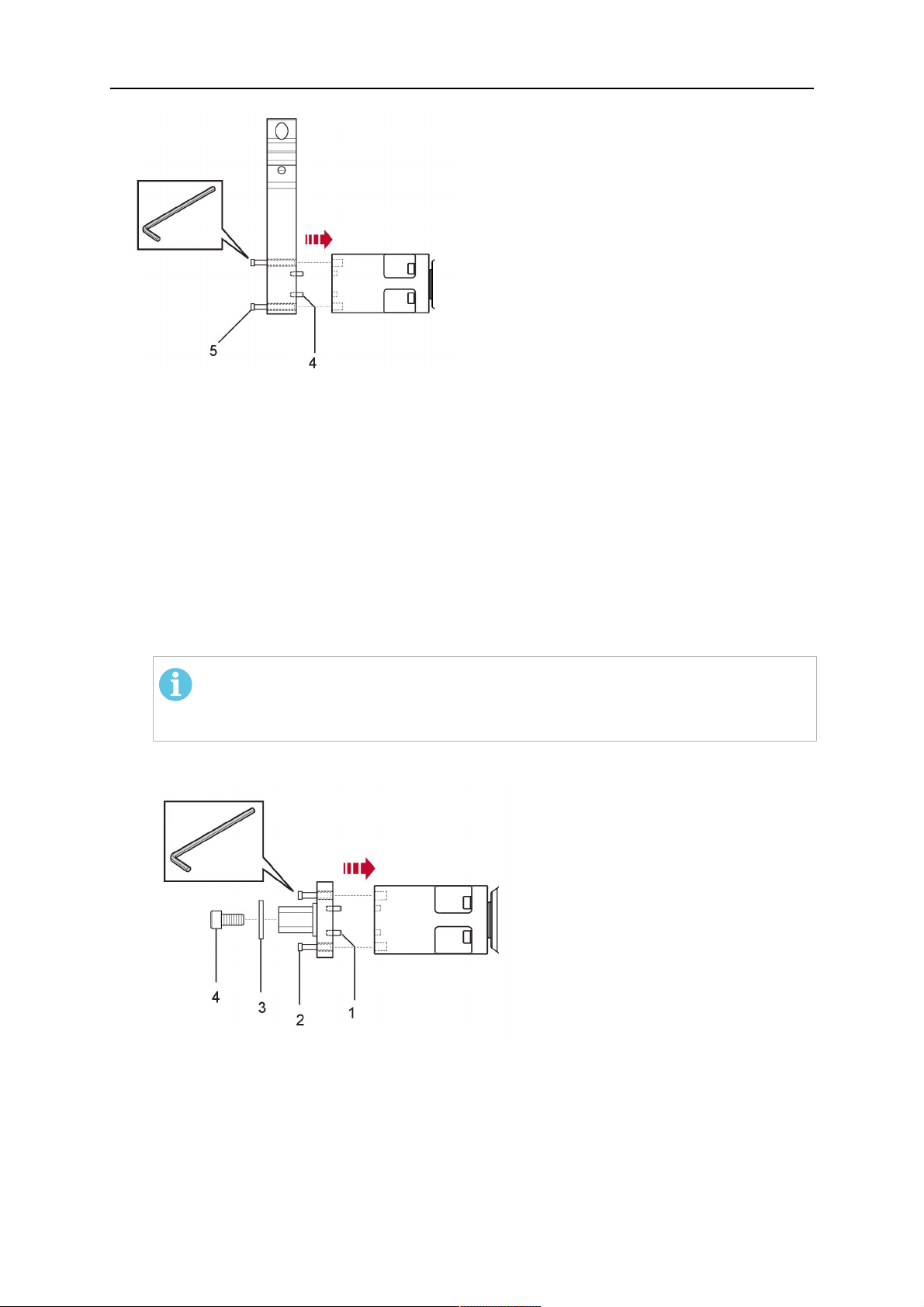
1. Remove the three screws (2) from the front cover (3) of the torch mount and carefully
pull the cover off the RTKSC-2 main body (5). Take care not to damage the micro
switches installed inside the assembly.
1 - Hexagon wrench 4 mm 4 - Rubber boot
2 - 3× M5×12 screws 5 - RT KSC-2 main body
3 - RT KSC-2 front cover
1. Pull off the rubber boot (4) from the RTKSC-2 main body (5) to the front.
2. Now position the RTKSC-2 main body (5) on the adapter flange (7) so that the index
pin is correctly seated. Attach with the screws (6) enclosed.
3. Reinstall the rubber boot (4) on the RTKSC-2 main body (5) and make sure it is
correctly located in the grooves on the front and back flange.
4. Istall the adapter flange (7) on the robot.
Fastening torque max. 2.2 Nm (19.5 in.lb).
1 - Hexagon wrench 4 mm 3 - 3× M5×12 hexagon socket screws
2 - Rubber boot 4 - Adapter flange
5.3.2 Mounting the cable assembly
OBS!
In order to adjust the wire feeder position to the cable assembly length, it must be
mounted on an adjustable support with a possible movement of ±2-3cm (±1in.) to
the back and to the front. The length of the cable assembly must be determined
from the centred mounting position of the wire feeder.
1. Move the robot arm into a completely straight position, see illustration below. Make
sure that (1) axis 6 (rotation around the torch axis) is in 0° position.
2. Move the feeder (3) completely to the back in order to create space for inserting the
cable assembly. If it is not possible to move the feeder sufficiently, it should be
removed from the robot.
0463 373 101
- 31 -
© ESAB AB 2018

5 INSTALLATION
3. Insert the cable assembly with the coupling (2) first into the robot arm and feed it
through the robot wrist.
4. The feeder should only be installed again after the correct mounting position with
respect to the cable length has been determined. (See section "Installing the cable
assembly").
FORSIKTIG!
Axis 6 must be in 0° position.
5.3.2.1 RTKSC-2 feeder cabinet connections
When installed for the first time, the position of the wire feeder cabinet must be adjusted to
the length of the cable assembly. First, the robot arm must be fully extended (straight).
FORSIKTIG!
As long as the correct position of the feeder corresponding to the length of the cable
assembly has not been determined, be careful when moving the robot arm and
avoid overstretching the cable. It is helpful to loosen the positioning screws of the
feeder before moving the robot arm to allow the feeder to follow the cable assembly.
0463 373 101
- 32 -
© ESAB AB 2018

5 INSTALLATION
1. Loosen the sliding mechanism of the wire feeder and connect the cable assembly.
2. Now adjust the position of the wire feeder to suit the length of the Infiniturn or Helix
cable, as indicated with "A" in the illustration below.
FORSIKTIG!
When adjusting the position of the feeder cabinet, make sure that the cable
assembly is not under stress when the robot arm is in stretched-out position.
It is normal for the cable assembly to sag slightly, it should never be taut.
3. Before securing the wire feeder in its permanent position, ensure that the Euro
connectors are tightly connected. Then turn the torch mount down and up again
(rotating on the axis 5), in order not to tighten the cable assembly too much against
the feeder (see illustration above). Once this is done, tighten the feeder in that
position.
4. For water cooled systems, connect the water lines to the cooling circuit. See section
"Cable assemblies for hollow wrist systems" in the TECHNICAL DATA chapter for
indications.
The hose with the blue rubber cap is for cooling water to the torch, the hose with the
red rubber cap returns the heated water. Make sure the hoses will not kink or get
otherwise blocked.
OBS!
A Helix cable assembly used for a gas cooled system must not be connected
to a cooling circuit. As the water connections are not needed, they may be cut
off.
5. Connect the blow-out hose (black rubber cap) to the corresponding outlet of the wire
feeder.
OBS!
If the blow-out function is not used, the blow-out hose must be sealed with the
rubber cap enclosed. With Infiniturn systems, the blow-out air must be
supplied to the corresponding connection hose, if it is not permitted to connect
blow-out air to the shield gas connection!
6. Install the necessary plug on the control cable and connect it to the safety off circuit
interface of the wire feeder (see section "Electrical connections").
0463 373 101
- 33 -
© ESAB AB 2018

5 INSTALLATION
5.3.3 RTKSC-2 cable assembly
The cable assembly must be aligned to the intended use in length and design. The type of
cooling for the torch and the cable assembly must be the same (either gas or water cooled
respectively). In order to prevent damage to the torch system and other components, it is
imperative to observe the following instructions.
FORSIKTIG!
• Coordinate the length and design of the cable assembly to suit the range of
action of the robot.
• Do not bend, compress or overstretch the cable assembly.
• Fix the cable assembly such that is can be moved freely and cannot become
entangled.
• Any additional holding devices possibly installed, for example a balancer,
must not crush or bend the cable assembly.
• Extreme turning movements must be avoided in which the cable assembly
may become twisted.
• Chafing on the robot or other objects must be excluded.
5.3.3.1 RTKSC-2 cable assembly installation
OBS!
For some robots, it may be possible to deviate from this order, and first connect the
cable assembly to the RTKSC-2, then thread the cable from the front through the
robot arm. If in doubt, follow the suggested order.
1. Loosen the three screws (7) with the associated washers and remove them from the
RTKSC-2 cover (1). See illustration below.
2. Install the supplied O-rings (4) into the grooves in the cover (1).
3. Pull the cable assembly approximately 15 cm (6 in.) from the main body (3).
0463 373 101
- 34 -
© ESAB AB 2018

5 INSTALLATION
4. Insert the coupling (2) into the socket of the cover (1) as shown. Align the index pin (6)
with the index hole (5) in the main body and insert completely.
OBS!
Make sure that the position of the O-rings are not shifted by the index pin
during the assembly.
1 - RTKSC-2 cover 5 - Index hole
2 - Coupling 6 - Index pin
3 - RTKSC-2 main body 7 - 3× M5×35 screws
4 - 3× O-ring for water cooled systems 11 - Control cable connector
5. Insert the three screws (7) with the associated washers (8) and tighten gently with the
enclosed hexagonal wrench, see below illustration.
Fastening torque approximately 2 Nm (18 in.lb).
0463 373 101
- 35 -
© ESAB AB 2018

5 INSTALLATION
6. If present, insert the control cable plug (10) into the connector (11) and make sure it is
firmly seated.
7 - 3× M5×35 screw 11 - Control cable connector
8 - Washer 12 - 2× Micro switch
10 - Control cable plug 13 - Index pin
7. Gently push back the cable assembly into the robot arm and carefully seat the
RTKSC-2 cover (1) in place. Observe the index pin (13) to be in the correct position.
Make sure the two micro switches (12) are not damaged if present.
8. Insert the three M5 screws (14) and tighten without excessive force.
13. Index pin
14. 3× M5×12 screws
0463 373 101
- 36 -
© ESAB AB 2018

5 INSTALLATION
5.3.3.2 RTKSC-2 electrical connections
OBS!
After connecting the control cable, secure the cable in order to protect it from getting
caught while the robot is moving.
Usually, the control cable will be directly connected to the wire feeder. See the
manufacturer's documentation for details. The link to the robot control is then
implemented via the power source controller.
RTKSC-2 safety-off mechanism connection
The switch for the safety-off functionality RTKSC-2 is connected through the control cable,
see (3) in the illustration below. This connects to the RTKSC-2 unit via the control cable plug
(1).
The safety-off signal requires a 2-wire connection (black/black) to the safety-off circuit in the
robot control (5).
If a collision is detected, the control circuit (normally closed) will be interrupted (4).
Rating of the control circuit: max. 48 V / 1 A.
1 - Control cable plug 3 - Burndy connector VVV
2 - EURO central connector
Burndy-kontaktpinner
A. Touch sense-gassdyse
C. Kollisjonssensor
D. Kollisjonssensor
F. 0V
G. motorspenning +
G. motorspenning –
E. Justering
RTKSC-2 nozzle sense function connection
If the robot control provides a control circuit for nozzle sense functionality.
The connection is accomplished with a 2-wire connection (black/black) to the nozzle sense
circuit in the robot control (5), see illustration below.
0463 373 101
- 37 -
© ESAB AB 2018

5 INSTALLATION
Usually, the control cable will be directly connected to the wire feeder. See the
manufacturer's documentation for details. The link to the robot control is then implemented
via the power source robot interface.
Rating of the control circuit: max. 50 V / 5 A.
FARE!
If the nozzle sense function is not being used, the open end of the control cable on
the power source connection side must be properly isolated in order to avoid short
circuits. During certain problems on the torch head, the full welding potential may be
present on this cable.
FORSIKTIG!
After detection of contact (gas nozzle on work piece), quickly reduce or cut off the
maximum current in the nozzle sense circuit in order to avoid overloading of the
system.
Allowed load max. 1 minute at the rated nominal current.
1 - Control cable plug 3 - Control cable
2 - EURO central connector
5.3.4 RTKSC-2 torch installation
Continue according to section "Torch installation".
0463 373 101
- 38 -
© ESAB AB 2018

5 INSTALLATION
5.4 RTFLC-2 installation
5.4.1 RTFLC-2 mount
1. Remove the three M5 screws (2) from the front cover (3) of the RT FLC-2 torch mount
and carefully pull the cover off the main body (4).
1 - Hexagon wrench 4 mm 3 - RT FLC-2 front cover
2 - 3× M5×12 screws 4 - RT FLC-2 main body
2. Now position the RT FLC-2 main body (4) on the adapter flange (6) so that the index
pin is correctly seated. Attach with the screws (5) enclosed
Fastening torque max. 2.2 Nm (19.5 in.lb).
1 - Hexagon wrench 4 mm 5 - 3× M5×12 hexagon socket screws
4 - RT FLC-2 main body 6 - Adapter flange
5.4.2 RTFLC-2 wire feeder connection
5.4.2.1 Feeding through the robot arm
OBS!
In order to adjust the wire feeder position to the cable assembly length, it must be
mounted on an adjustable support with a possible movement of ± 2-3 cm (± 1 in.) to
the back and to the front. The length of the cable assembly must be determined
from the centred mounting position of the wire feeder.
0463 373 101
- 39 -
© ESAB AB 2018

5 INSTALLATION
1. Move the robot arm into a completely straight position, see illustration below. Make
sure that (1) axis 6 (rotation around the torch axis) is in 0° position.
2. Move the feeder (3) completely to the back in order to create space for inserting the
cable assembly. If it is not possible to move the feeder sufficiently, it should be
removed from the robot.
3. Insert the cable assembly with the coupling (2) first into the robot arm and feed it
through the robot wrist.
4. The feeder should only be installed again after the correct mounting position with
respect to the cable length has been determined. (See section "Installing the cable
assembly").
FORSIKTIG!
Important! Axis 6 must be in 0° position.
5.4.2.2 RTFLC-2 feeder cabinet connections
When installed for the first time, the position of the wire feeder cabinet must be adjusted to
the length of the cable assembly. First, the robot arm must be fully extended (straight).
FORSIKTIG!
As long as the correct position of the feeder corresponding to the length of the cable
assembly has not been determined, be careful when moving the robot arm and
avoid overstretching the cable. It is helpful to loosen the positioning screws of the
feeder before moving the robot arm to allow the feeder to follow the cable assembly.
0463 373 101
- 40 -
© ESAB AB 2018

5 INSTALLATION
1. Loosen the sliding mechanism of the wire feeder and connect the cable assembly.
Refer to the instruction of the feeder manufacturer.
2. Now adjust the position of the wire feeder to suit the length of the Infiniturn or Helix
cable, as indicated with "A" in the illustration below.
FORSIKTIG!
When adjusting the position of the feeder cabinet, make sure that the cable
assembly is not under stress when the robot arm is in stretched-out position.
It is normal for the cable assembly to sag slightly, it should never be taut.
3. Before securing the wire feeder in its permanent position, ensure that the Euro
connections are tightly connected. Then turn the torch mount down and up again
(rotating on the axis 5), in order not to tighten the cable assembly too much against
the feeder (see illustration above). Once this is done, tighten the feeder in that
position.
4. For water cooled systems, connect the water lines to the cooling circuit. See section
"Cable assemblies for hollow wrist systems" in the TECHNICAL DATA chapter for
indications.
The hose with the blue rubber cap is for cooling water to the torch, the hose with the
red rubber cap returns the heated water. Make sure the hoses will not kink or get
otherwise blocked.
OBS!
A Helix cable assembly used for a gas cooled system must not be connected
to a cooling circuit. As the water connections are not needed, they may be cut
off.
5. Connect the blow-out hose (black rubber cap) to the corresponding outlet of the wire
feeder.
OBS!
If the blow-out function is not used, the blow-out hose must be sealed with the
rubber cap enclosed. With Infiniturn systems, the blow-out air must be
supplied to the corresponding connection hose, if it is not permitted to connect
blow-out air to the shield gas connection!
0463 373 101
- 41 -
© ESAB AB 2018

5 INSTALLATION
6. Install the necessary plug on the control cable and connect it to the safety off circuit
interface of the wire feeder (see section "Electrical connections").
5.4.3 RTFLC-2 cable assembly
The cable assembly must be aligned to the intended use in length and design. The type of
cooling for the torch and the cable assembly must be the same (either gas or water cooled
respectively). In order to prevent damage to the torch system and other components, it is
imperative to observe the following instructions.
FORSIKTIG!
• Coordinate the length and design of the cable assembly to suit the range of
action of the robot.
• Do not bend, compress or overstretch the cable assembly.
• Fix the cable assembly such that is can be moved freely and cannot become
entangled.
• Any additional holding devices possibly installed, for example a balancer,
must not crush or bend the cable assembly.
• Extreme turning movements must be avoided in which the cable assembly
may become twisted.
• Chafing on the robot or other objects must be excluded.
5.4.3.1 RTFLC-2 cable assembly installation
In a hollow wrist system the recommended order of installation is to feed the cable assembly
through the robot arm before connecting the cables to the torch mount.
When the cable assembly is correctly installed in the hollow wrist, continue the installation
according to the procedure described below.
OBS!
For some robots, it may be possible to deviate from this order, and first connect the
cable assembly to the RTKSC-2 and RTFLC-2, then thread the cable from the front
through the robot arm. If in doubt, follow the suggested order.
1. Loosen the three screws (7) with the associated washers and remove them from the
RTFLC-2 cover (1). See illustration below.
2. Install the supplied O-rings (4) into the grooves in the cover (1). For gas cooled
systems, only one O-ring (4a) is needed, for water cooled systems all three O-rings
are needed.
3. Pull the cable assembly approximately 15 cm (6 in.) from the main body (3).
0463 373 101
- 42 -
© ESAB AB 2018

5 INSTALLATION
4. Insert the coupling (2) into the socket of the cover (1) as shown. Align the index pin (6)
with the index hole (5) in the main body and insert completely.
OBS!
Take great care that the position of the O-rings is not shifted by the index pin
during the assembly.
1 - RT FLC-2 cover 5 - Index hole
2 - Coupling 6 - Index pin
3 - RT FLC-2 main body 7 - 3× M5×35 screws
4 - 3× O-ring for water cooled systems 11 - Control cable connector
5. Insert the three screws (7) with the associated washers (8) and tighten gently with the
enclosed hexagonal wrench, see below illustration.
Fastening torque approximately 2 Nm (18 in.lb).
0463 373 101
- 43 -
© ESAB AB 2018

5 INSTALLATION
6. If present insert the control cable plug (10) into the connector (11) and make sure it is
firmly seated.
7 - 3× M5×35 screw 11 - Control cable connector
8 - Washer 12 - 2× Micro switch
10 - Control cable plug 13 - Index pin
7. Gently push back the cable assembly into the robot arm and carefully seat the
RTFLC-2 cover (1) in place. Observe the index pin (13) to be in the correct position.
Make sure the two micro switches (12) are not damaged if present.
8. Insert the three M5 screws (14) and tighten without excessive force.
13 - Index pin 14 - 3x M5x12 screws
0463 373 101
- 44 -
© ESAB AB 2018

5 INSTALLATION
5.4.4 RTFLC-2 electrical connections
OBS!
After connecting the control cable, secure the cable in order to protect it from getting
caught while the robot is moving.
Usually, the control cable will be directly connected to the wire feeder. See the
documentation of the manufacturer for details. The link to the robot control is then
implemented via the power source controller.
5.4.4.1 RTFLC-2 hollow wrist system with Infiniturn cable assembly
Connecting the nozzle sense function
If the robot control provides a control circuit for nozzle sense functionality.
The connection is accomplished with a 2-wire connection (black/black) to the nozzle sense
circuit in the robot control (5), see illustration below.
Usually, the control cable will be directly connected to the wire feeder. See the
manufacturer's documentation for details. The link to the robot control is then implemented
via the power source robot interface.
Rating of the control circuit: max. 50 V / 5 A.
FARE!
If the nozzle sense function is not being used, the open end of the control cable on
the power source connection side must be properly isolated in order to avoid short
circuits. During certain problems on the torch head, the full welding potential may be
present on this cable.
FORSIKTIG!
After detection of contact (gas nozzle on work piece), quickly reduce or cut off the
maximum current in the nozzle sense circuit in order to avoid overloading of the
system.
Allowed load max. 1 minute at the rated nominal current.
1 - Control cable plug 3 - Control cable
2 - EURO central connector
0463 373 101
- 45 -
© ESAB AB 2018

5 INSTALLATION
5.4.4.2 RTFLC-2 hollow wrist system with Helix cable assembly
Connecting the nozzle sense function
If the robot control provides a control circuit for nozzle sense functionality.
The connection is accomplished with a 1-wire connection (green) to the nozzle sense circuit
in the robot control (5), see illustration below.
Usually, the control cable will be directly connected to the wire feeder. See the
manufacturer's documentation for details. The link to the robot control is then implemented
via the power source robot interface.
Rating of the control circuit: max. 50 V / 5 A.
FARE!
If the nozzle sense function is not being used, the open end of the control cable on
the power source connection side must be properly isolated in order to avoid short
circuits. During certain problems on the torch head, the full welding potential may be
present on this cable.
FORSIKTIG!
After detection of contact (gas nozzle on work piece), quickly reduce or cut off the
maximum current in the nozzle sense circuit in order to avoid overloading of the
system.
Allowed load max. 1 minute at the rated nominal current.
1 - Control cable plug 3 - EURO central connector
2 - Control cable 4 - Burndy connector
5.5 Torch installation
Be sure to use the correct version of the torch mount and cable assembly (water or gas
cooled).
5.5.1 Torch neck equipment
The torch neck, see (1) in the illustration below, must always be equipped to suit the wire
diameter and material.
0463 373 101
- 46 -
© ESAB AB 2018

5 INSTALLATION
1. Select the correct wire guide, contact tip (4), tip holder (2), gas nozzle (5), and gas
diffuser/spatter protection (3). You will find an exact overview and possible alternative
equipment elements for various torch models in the spare parts list. Only use original
ESAB parts; only then is the fitting accuracy ensured.
2. Firmly tighten the tip holder and the contact tip using a suitable tool for example the
enclosed monkey wrench.
3. When using a split wire guide, remove the installed guide nipple including the o-ring
from the torch flange upon delivery if necessary (see section "Installing the neck
liner").
FORSIKTIG!
The torch must be completely equipped before welding, especially the gas
diffuser and/or spatter protection and all necessary insulators have to be
installed according to the spare parts list. Welding without these items may
cause immediate destruction of the torch.
1 - Torch neck 4 - Contact tip
2 - Tip holder 5 - Contact tip
3 - Gas diffuser
5.5.2 Aristo RT torch neck installation
OBS!
Check the O-rings on the flange of the torch neck before mounting. Replace the
O-rings if damaged or lost. Missing or faulty O-rings will lead to leaks of shielding
gas and coolant.
1. For hollow wrist systems, insert the torch into the torch mount in the correct
orientation, so that the locator pin fits into the slot of the RTKSC-2 or RTFLC-2
interface, see (A) in the illustration below. For standard systems, attach the torch to
the RT flange of the cable assembly, (B) in the illustration below.
Installation is only possible in the correct orientation.
2. Tighten the locking nut of the torch neck.
OBS!
Only tighten by hand, never use tools or excessive force.
0463 373 101
- 47 -
© ESAB AB 2018

5 INSTALLATION
3. The correct seating of the torch can be checked by means of the window (1). If the
torch has been correctly mounted, no gap should be seen through the window (1).
5.6 Installing the wire guide for standard and hollow Wrist arm
Installing the wire guide
Choose the wire guide or liner depending on the filler wire material and diameter to be used,
see the spare parts list. Accurate performance of the system can only be guaranteed when
using original ESAB wire guides.
The recommended wire guide is the split wire guide, which consists of the neck liner and a
separate guide in the cable assembly. The front part of the wire guide, which is most
stressed, can be exchanged easily and independently of the cable assembly wire guide.
For correct installation, the following steps must be followed (example for Euro central
connector).
5.6.1 Installing the neck liner
The neck liner must be selected to fit the material and diameter of the welding wire, see the
spare parts list.
0463 373 101
- 48 -
© ESAB AB 2018

5 INSTALLATION
1. If present, remove the central guide nipple (1), from the torch neck using a hexagon
wrench (size 6 mm) or a large flat-blade screwdriver.
OBS!
The guide nipple (1) can only be used with one-piece liners and must not be
used with the standard RT or hollow wrist system.
2. When replacing the neck liner:
Unfasten the sleeve nut and remove the torch neck.
Unfasten the liner nipple using a hexagon wrench (size 6 mm) and remove nipple and
liner from the torch neck.
3. Remove the gas nozzle and the contact tip.
4. Insert the new neck liner (2) into the torch. Carefully tighten the guide nipple using a
suitable tool, e.g. a hex-wrench (size 6 mm) or a large flat-blade screwdriver.
5. Cut the neck liner flush with the tip holder and remove the neck liner from the torch.
6. Install the contact tip.
7. Insert the neck liner again. It will be stopped by the contact tip. Measure the excess
liner sticking out of the neck.
8. Remove the liner again and shorten the front end by the measured length. Carefully
deburr the edge and make sure that the inner hole is not blocked.
9. Reinstall the neck liner and tighten the guide nipple in the neck.
5.6.2 Installing a split wire guide in the cable assembly
The correct liner must be inserted to suit the filler material and the wire diameter, see the
spare parts list.
The wire guide is inserted through the cable assembly from the rear, reaching the guide
nipple that is installed in the flange where the torch neck will be attached. The following
worksteps must be followed in order to correctly determine the wire guide length. (Example
for Euro central connector).
0463 373 101
- 49 -
© ESAB AB 2018

5 INSTALLATION
1. For standard RT system: Install the guide nipple (1) in the center hole of the neck
support flange, see illustration A below.
For hollow wrist system: Install the guide nipple (1) into the torch interface of the
RTKSC-2 / RTFLC-2 cover, see illustration B below.
2. Remove the sleeve nut (2) from the central connector, and remove the old wire guide.
3. Insert the wire guide through the central connection and push forwards as far as it will
go into the guide nipple (1), applying light pressure.
FORSIKTIG!
Ensure that the wire guide has advanced right up to the stop at the front,
rotating and pushing forward gently.
4. Measure the excess length that needs to be cut from the wire guide.
5. Remove the wire guide again and shorten the front end by the measured length.
Steel liner: grind down the burred edges if needed.
Plastic liner: make a clean cut and chamfer the edges (e.g. with a pencil sharpener)
OBS!
Make sure the inner opening of the liner is not obstructed by the cut wire end.
0463 373 101
- 50 -
© ESAB AB 2018

5 INSTALLATION
6. Reinstall the wire guide and attach the sleeve nut (2).
OBS!
For hollow wrist systems where Infiniturn and Helix cable assemblies are
used, wire guides should be installed without tension so that the ends of the
liners may rotate freely.
Important note when using a plastic liner:
The wire channel between the drive rolls of the feeder and the central
connector of the torch must be fitted with a plastic liner. Depending on the
design of the feeder, a piece of plastic liner inserted into a brass guide tube
can be used.
During wire run-in, make sure that the wire is fed correctly into the plastic liner
of the torch. If necessary, remove the cable assembly from the feeder and
insert the wire, then reattach.
5.6.3 Installing a continuous wire guide in the cable assembly
Installing a steel liner
The wire guide is inserted through the cable assembly from the rear and reaches to the
contact tip. The following worksteps must be followed for the correct calculation of the length
(example for Euro central connector):
1. Install the torch (see section "Torch neck equipment").
2. Remove the gas nozzle and contact tip from the torch.
3. Remove the sleeve nut (D) from the Euro connector.
4. Push in the liner through the central connector and fix with the sleeve nut.
5. Cut off the liner flush with the nozzle holder. To determine the thread projection of the
contact tip, pull the liner backwards and screw in the contact tip.
6. Push the liner forwards as far as it will go to the contact tip applying light pressure on
the liner and measure the length to be shortened at the rear.
7. Now remove the liner again and cut the excess length measured off it’s front end. If
needed, grind down the burred edges. Make sure the inner opening of the liner is not
obstructed by the cut wire end.
8. The insulation of the liner must be removed after cutting off in the front area, such that
the insulation protrudes out of the RM2 flange by approx. 5 cm. For this, briefly
remove the torch neck.
9. Push the liner back in again and fix with the sleeve nut (D), see above. Re-install the
gas nozzle.
0463 373 101
- 51 -
© ESAB AB 2018

5 INSTALLATION
Installing a plastic liner
1. Mount the torch neck (see section "Torch neck equipment") and equip it with a gas
nozzle and contact tip.
2. Remove the sleeve nut (D) from the Euro connector.
3. Cleanly cut off the liner, slightly break the outer edges, point slightly (e.g. with a pencil
sharpener).
4. Insert the liner through the central connector into the cable assembly with fitted torch.
If it gets stuck, rotate the liner to free it and facilitate installation.
OBS!
Make sure the liner is completely inserted by rotating it and slightly pushing it
forward, until you can feel it has reached its stop.
5. Mount the nipple (B) and the O-Ring (C), move it to the right position and fix it with the
sleeve nut (D) of the Euro central connector.
6. Measure the required overlap needed inside the wire feeder cabinet and cut the liner
accordingly.
5.7 Adjust the narrow gap contact tip
The adjusting tool RT42-NG is designed for the narrow gap torch necks RT42W-NG,
RT42G-NG and RT 82W-0°NG, torches with curved narrow gap contact tip. It facilitates the
precisely repeatable and fast changing of the curved contact tip.
OBS!
The adjusting tool must be securely fastened to a stable base, in order to prevent
the position of the device in relation to the robot cannot change unintentionally. If the
exact orientation of the device is lost, the alignment of the contact tip used for the
elaboration of the welding programs can no longer be reproduced with precision.
Select a position within the operating range of the robot for orientation (alignment) of the
contact tip to the torch. Fasten the adjusting tool firmly to a base using the fastening grooves
provided for this purpose. Fastening material is not included with the adjusting tool. Select
fastening material (screws) to suit the existing conditions.
Save all motion sequences and stop positions required to change or align the wearing parts
to a separate robot program.
Before programming the welding tasks: plan at which orientation the contact tip is to stand in
relation to the torch. The torch must then be positioned in the desired rotational position and
the contact tip aligned using the adjusting device. Only then may the welding task be
programmed. If different orientations of the contact tip are required for various welding tasks,
the contact tip has to be aligned to the new position when the welding task is changed.
ADVARSEL!
The gas nozzle and the torch head become very hot during welding. Always allow
the torch to cool down before replacing wearing parts or adjusting the contact tip.
0463 373 101
- 52 -
© ESAB AB 2018

5 INSTALLATION
Adjust the contact tip
Move the robot torch to a position parallel to
the opening of the adjusting tool (2). Maintain
a sufficient distance to the work table to be
able to comfortably remove the gas nozzle.
Define this position in your robot program as
the wearing parts change position (stop
position 1).
Remove the gas nozzle by pulling it
downwards. Remove the welding wire in the
contact tip if necessary.
Loosen the counter nut (4) of the contact tip
while counter-holding the nozzle holder at the
wrench flat (3).
Unscrew the contact tip including the counter
nut from the nozzle holder and replace the
nozzle holder if necessary.
Completely screw the counter nut (4) onto the
new contact tip. Screw the contact tip
including the counter nut into the nozzle
holder.
Align the contact tip until it is parallel to the
opening of the adjusting tool. If necessary,
slightly unscrew the contact tip so that it can
be easily turned in both directions.
0463 373 101
- 53 -
© ESAB AB 2018

5 INSTALLATION
OBS!
The contact tip must be able to be
easily moved by hand in both
directions in order to enable the
threading of the adjusting tool.
Place the robot torch or contact tip directly in
front of the opening of the adjusting tool (2)
(stop position 2).
Insert it slowly from the front until it is
completely inserted into the device (stop
position 3).
The contact tip was aligned exactly in the
device during insertion. Now cautiously
tighten the counter nut (4) in this position,
while counter holding the nozzle holder at the
wrench flat.
Slowly move the robot torch out of the
adjusting gauge, return to stop position 1 and
push on the gas nozzle as far as it will go.
Allow the welding wire to run into the contact
tip and bring the robot arm into welding
position.
0463 373 101
- 54 -
© ESAB AB 2018

6 OPERATION
6 OPERATION
FORSIKTIG!
Before starting the system, check the whole installation according to the
manufacturer's instructions and applicable safety regulations.
Check the following to make sure that the system has been installed correctly:
1. Are all parts securely attached (torch, torch mount, flanges, safety-off device, cable
assembly, and wire feeder cabinet)?
2. Are all media hoses connected correctly and protected from damage?
3. Is the EURO central connector or direct connector fastened tightly?
4. Is the cable assembly length correct and suitable for the installation and can the cable
rotate freely? The cable must not be bent sharply. Any risk of the cable getting caught
on another object must be eliminated.
5. Is the control cable of the safety-off circuit connected and functioning? Move torch by
hand to test (RTKSC-2 and RTKS-2 only).
6. Is the torch firmly attached and is it completely equipped?
7. Is the wire guide installed according to the manual?
8. Are all lines and tubes arranged so that they cannot be damaged or bent?
The wire run-in can now be started, either via the wire run-in pushbutton or via the wire run-in
at the feeder.
6.1 Important information for programming (hollow wrist system only)
Fast rotation of axis 6 of the robot will significantly stress the cable assembly. In certain
cases, this can lead to damage or destruction of the cable. In order to maximize the lifetime
of the cable, we strongly suggest respecting the following limitations when programming the
robot.
Position of axis 5 Max. rotational speed of axis 6
0 – 60° 100 % (no limitations)
60° – 80° 300°/sec (approximately 50 % of max. robot speed)
> 80° 120°/sec (approximately 20 % of max. robot speed)
OBS!
The above values are only indications. For information on the exact rotational speed
limits, refer to the individual robot manual or contact the robot supplier.
To reposition the torch quickly, the robot arm may have to be slightly extended first to achieve
a bending angle of max. 60° of axis 5. In this position, the maximum available rotation speed
of axis 6 can be used.
When using the ESAB Helix cable assembly, the max. rotation of ±270° from the neutral
position must not be exceeded.
0463 373 101
- 55 -
© ESAB AB 2018

6 OPERATION
FORSIKTIG!
While axis 5 is bent more than 60°, the rotational speed of the torch around axis 6
must be limited, see table above.
Otherwise, the cable assembly may be damaged.
0463 373 101
- 56 -
© ESAB AB 2018

7 SERVICE OG VEDLIKEHOLD
7 SERVICE OG VEDLIKEHOLD
ADVARSEL!
Før du utfører vedlikehold på systemet må hovedstrømmen til installasjonen være
slått av. Overhold sikkerhetsforskriftene i begynnelsen av denne håndboken.
Skadde brennere eller kabler må ikke brukes! Kjente defekter må repareres av
kvalifisert personell før neste bruk av utstyret.
ADVARSEL!
Fare for brannskader! Gassdysen og brennerhodet bli svært varme under sveising.
La brenneren avkjøles før vedlikeholdsarbeid.
ADVARSEL!
Følg disse instruksjonene for å forhindre personskader eller skade på installasjonen:
1. Reparasjon av RTKSC-2- eller RT FLC-2-brennerfeste,
RTKS-2-sikkerhetsmekanisme, kabel eller Infiniturn-mediakoblingen må
bare utføres av ESAB-servicepersonell.
2. Infiniturn-mediakoblingen må aldri åpnes. Den inneholder ingen deler som
kan repareres av brukeren og vil bli ødelagt ved demontering.
3. Aldri demonter RTKSC-2 eller RTKS-2. Dette er en fjærbelastet
mekanisme. Feil bruk kan føre til alvorlig skade.
7.1 Obligatoriske kontroller og tiltak
Før hver bruk:
• Kontroller brenner, kontaktmunnstykke, gassdyse, halsleder, kabler og det generelle
utstyret for generell skade.
OBS!
For å minimere nedetid anbefales det å veksle mellom to brennerhalser og alltid ha
en nyutstyrt brennerhals for hånden og klar til bruk.
Hver 8. times bruk (avhengig av bruksområde):
• Endre kontaktmunnstykket.
Daglig:
• Utfør en funksjonskontroll av sikkerhetsmekanismen for hånd.
• Utfør en visuell kontroll for skader – f.eks. bøyer eller sprekker.
• Kontroller riktig plassering av trådmateren. Kabelen må ikke være for stram eller slapp.
• Kontroller mediakontaktene og Infiniturn-mediakoblingen for lekkasje.
• Utfør rengjøring og vedlikehold av brenneren i henhold til brennerhåndboken.
Hver 40. times bruk (avhengig av bruksområde):
• Skift trådleder.
• Skift halsleder.
Ukentlig eller etter behov, avhengig av bruk:
• Fjern trådlederen og sjekk for slitasje og smussavleiringer. Skift ut ved behov.
Månedlig eller oftere ved kraftig bruk (dvs. mer enn 8 timer/dag):
0463 373 101
- 57 -
© ESAB AB 2018

7 SERVICE OG VEDLIKEHOLD
• Blås ut trådlederkanalen med trykkluft (fjern kontaktmunnstykket og trådlederen).
• Kontroller at alle skruene er trukket til.
• Kontroller alle koblinger og slanger med tanke på skader.
• Bytt etter 250kg sveiset ledning.
Skader på den elektriske isolasjonen må repareres av opplært personell før systemet trygt
kan betjenes.
0463 373 101
- 58 -
© ESAB AB 2018

8 FEILSØKING
8 FEILSØKING
Feil Mulig årsak Tiltak
Kan ikke mate
tråd
Brenneren blir
for varm
Sveisetråden har ikke blitt rettet før
den føres inn i kabelen
Brenneren og kabelen er ikke riktig
utstyrt for tråddiameter og
trådmaterialet
Trådlederen er ikke satt riktig inn i
kabelen
Kontaktmunnstykket er blokkert av
ledningsrester
Trådlederen er slitt
Trådlederen hindres av smuss og
rusk i brenneren
Kontaktmunnstykket eller
munnstykkeholderen er ikke riktig
trukket til
Trekk om nødvendig sveisetråden
ut igjen, kutt av og avgrader enden,
og rett ut de første 10cm av tråden.
Træ deretter tilbake i kabelen.
Kontroller trådlederen (kabel og
brennerhals) og
kontaktmunnstykket.
Trekk trådlederen litt ut fra
Euro-kontakten. Når du fører inn
trådlederen, bør du føle at de siste
centimeterne gli inn i
føringsnippelen i
brennerberøringspunktet. Ellers kan
trådlederen være for kort og ikke
ført helt inn.
Skift ut kontaktmunnstykket og/eller
trådlederen, blås ut av
brennerhalsen, trådlederkanalen og
trådlederen med trykkluft.
Bruk et egnet verktøy til å trekke til
for hånd.
Trådmatingspro
blemer
Kjølesystemet fungerer ikke godt. Kontroller vannstrømning,
fyllingsnivå og renslighet.
Kjølesystemet er ikke riktig tilkoblet Kontroller tilkoblingene (vanninntak
og -tilbakeløp).
Brenneren er overbelastet. Overhold tekniske data, velg om
nødvendig en annen type.
Feil på kabelen. Kontroller kabler, rør og tilkoblinger.
Kontaktmunnstykket er slitt. Bytt ut kontaktmunnstykket.
Lederen er slitt/skitten. Kontroller lederen, blås ut smuss.
Skift ut ved behov.
Forbruksartikler som brukes, er ikke
Kontroller reservedelslisten.
egnet for tråddiameteren eller
-materialet.
Trådmating er ikke installert riktig. Kontroller trådmatingsrullene,
kontakttrykket og spolebremsen.
Kabelen er bøyd eller lagt i for små
radier.
Kontroller om kabelen er skadet.
Kan lederen lett føres inn? Monter
som instruert. Se avsnittet Montere
kabelen.
Tråden er tilsmusset. Bruk en rensefilt.
0463 373 101
- 59 -
© ESAB AB 2018

8 FEILSØKING
Feil Mulig årsak Tiltak
Trådmatingen
Trådspolen er tom Kontroller mengden sveisetråd på
stopper under
sveising
Trådblokkering i kabelen Kontroller trådmatingen (muligens
Tråden brenner tilbake i
kontaktmunnstykket eller det slitte
kontaktmunnstykket
Sveiseprosesse
n stopper
Sikkerhetsutkoblingsmekanismen er
utløst.
Porer i sømmen Gassvirvel forårsaket av sprutende
materiale som fester seg.
For liten eller svært høyt gasstrøm i
brenneren.
Feil på gassforsyning. Kontroller strømningshastigheten og
spolen i trådmatingen.
for rask), kontroller om
kontaktmunnstykket er
tilsmusset/tilstoppet, rengjør eller
skift ut kontaktmunnstykket om
nødvendig.
Skift ut kontaktmunnstykket.
Søk etter kollisjonssteder, og hindre
dem. Kontroller om det er en løs
kontakt i styreledningen.
Rengjør brennerhodet, bruk
gasspreder/sprutbeskyttelse.
Kontroller strømningshastigheten
med måleverktøyet.
mulig lekkasje.
Buen er ikke
stabil
Fuktighet eller tilsmussing på tråden
eller på arbeidsstykket.
Kontroller tråden og arbeidsstykket,
bruk mindre eller en annen
antisprutvæske.
Kontaktmunnstykket er slitt. Bytt ut kontaktmunnstykket.
Feil sveiseparametre. Kontroller monteringen av
sveiseutstyret.
Ikke tilstrekkelig elektriske
tilkoblinger i kretsen
Kontroller at alle elektriske koblinger
(inkludert jordingskabel) mellom
strømkilden, brenneren og
arbeidsstykket sitter fast.
0463 373 101
- 60 -
© ESAB AB 2018

9 BESTILLING AV RESERVEDELER
9 BESTILLING AV RESERVEDELER
FORSIKTIG!
Reparasjoner og elektrisk arbeid skal utføres av en godkjent servicetekniker fra
ESAB. Bruk bare originale reserve- og slitedeler fra ESAB.
ESAB RT-brennere RTKS-2, RTFL-2, RT-KSC-2, RT-FLC-2, RT42, RT52, RT62, RT72,
RT82, RT42-NG og RT82WNG er utformet og testet i samsvar med internasjonale og
europeiske standarder IEC/EN 60974-7. Serviceavdelingen som har utført service eller
reparasjon, er forpliktet å sørge for at produktet fortsatt er i samsvar med angitt standard.
Reservedeler og slitedeler kan bestilles gjennom nærmeste ESAB-forhandler. Se esab.com.
Når du bestiller, må du angi produkttype, serienummer, betegnelse og reservedelsnummer i
samsvar med reservedelslisten. Dette forenkler forsendelsen og sikrer riktig levering.
0463 373 101
- 61 -
© ESAB AB 2018

ESAB AB, Lindholmsallén 9, Box 8004, 402 77 Gothenburg, Sweden, Phone +46 (0) 31 50 90 00
http://manuals.esab.com
For contact information visit esab.com
 Loading...