


RT Robo Welding Torch System
RTKS-2, RTFL-2, KSC-2, FLC-2, RT42, RT52,
RT62, RT72, RT82, RT42-NG, RT82WNG
Manuel d'instructions
0463 373 101 FR 20181227


TABLE DES MATIÈRES
1
SÉCURITÉ ................................................................................................... 5
1.1 Signification des symboles ................................................................... 5
1.2 Précautions de sécurité ......................................................................... 5
2
GARANTIE................................................................................................... 9
2.1 Conditions d'utilisation prévue ............................................................. 9
3
INTRODUCTION.......................................................................................... 10
3.1 Aperçu des systèmes de torche de soudage ...................................... 11
4
CARACTÉRISTIQUES TECHNIQUES ........................................................ 13
4.1 Col de torche de soudage...................................................................... 13
4.2 Tension nominale ................................................................................... 15
4.2.1 Limites du circuit de refroidissement .................................................... 15
4.3 Support de la torche............................................................................... 16
4.3.1 Supports de torche pour système RT standard.................................... 16
4.3.1.1 Mécanisme de sécurité RTKS-2....................................................... 17
4.3.1.2 Bride intermédiaire RTFL-2 .............................................................. 17
4.3.2 Supports de torche pour système à poignet creux............................... 17
4.3.2.1 Support de torche RTKSC-2 G/W avec mécanisme de sécurité...... 19
4.3.2.2 Support de torche rigide RTFLC-2 G/W ........................................... 20
4.4 Brides d'adaptation ................................................................................ 21
4.5 Ensembles de câbles ............................................................................. 21
4.5.1 Ensembles de câbles pour système RT standard ................................ 21
4.5.2 Ensembles de câbles pour systèmes à poignet creux ......................... 22
5
INSTALLATION............................................................................................ 24
5.1 RTKS-2 standard arm installation........................................................ 24
5.1.1 RTKS-2 safety-off mechanism............................................................. 24
5.1.1.1 Torch installation with adjustable mount............................................ 25
5.1.2 Standard arm cable assembly for KS-2 and FL-2 ................................ 27
5.1.3 RTKS-2 wire feeder connection........................................................... 28
5.1.4 RTKS-2 electrical connections ............................................................ 29
5.1.4.1 RTKS-2 safety-off mechanism connection ....................................... 29
5.1.5 RTKS-2 Torch installation .................................................................... 30
5.2 RTFL-2 standard arm installation ........................................................ 31
5.2.1 RTFL-2 rigid mount.............................................................................. 31
5.2.2 RTFL-2 torch installation ..................................................................... 33
5.3 RTKSC-2 hollow wrist system installation.......................................... 33
5.3.1 RTKSC-2 mount with safety off mechanism........................................ 33
5.3.2 Mounting the cable assembly............................................................... 34
5.3.2.1 RTKSC-2 feeder cabinet connections .............................................. 35
5.3.3 RTKSC-2 cable assembly ................................................................... 37
5.3.3.1 RTKSC-2 cable assembly installation .............................................. 37
5.3.3.2 RTKSC-2 electrical connections....................................................... 40
0463 373 101 © ESAB AB 2018

TABLE DES MATIÈRES
5.3.4 RTKSC-2 torch installation .................................................................. 41
5.4 RTFLC-2 installation.............................................................................. 42
5.4.1 RTFLC-2 mount................................................................................... 42
5.4.2 RTFLC-2 wire feeder connection......................................................... 42
5.4.2.1 Feeding through the robot arm.......................................................... 42
5.4.2.2 RTFLC-2 feeder cabinet connections............................................... 43
5.4.3 RTFLC-2 cable assembly .................................................................... 45
5.4.3.1 RTFLC-2 cable assembly installation ............................................... 45
5.4.4 RTFLC-2 electrical connections .......................................................... 48
5.4.4.1 RTFLC-2 hollow wrist system with Infiniturn cable assembly........... 48
5.4.4.2 RTFLC-2 hollow wrist system with Helix cable assembly................. 49
5.5 Torch installation.................................................................................... 49
5.5.1 Torch neck equipment .......................................................................... 49
5.5.2 Aristo RT torch neck installation........................................................... 50
5.6 Installing the wire guide for standard and hollow Wrist arm ............. 51
5.6.1 Installing the neck liner......................................................................... 51
5.6.2 Installing a split wire guide in the cable assembly ................................ 52
5.6.3 Installing a continuous wire guide in the cable assembly ..................... 54
5.7 Adjust the narrow gap contact tip ........................................................ 55
6
OPERATION ................................................................................................ 58
6.1 Important information for programming (hollow wrist system only) 58
7
ENTRETIEN ET MAINTENANCE ................................................................ 60
7.1 Contrôles et mesures obligatoires ....................................................... 60
8
DÉPANNAGE............................................................................................... 62
9
COMMANDE DE PIÈCES DE RECHANGE ................................................ 65
Sous réserve de modifications techniques sans avertissement préalable.
0463 373 101 © ESAB AB 2018
1 SÉCURITÉ
1 SÉCURITÉ
1.1 Signification des symboles
Tels qu'utilisés dans ce manuel: Signifie Attention! Soyez vigilant!
DANGER!
Signifie dangers immédiats qui, s'ils ne sont pas évités, entraîneront
immédiatement de graves blessures ou le décès.
AVERTISSEMENT!
Signifie risques potentiels qui pourraient entraîner des blessures ou le
décès.
ATTENTION!
Signifie risques qui pourraient entraîner des blessures légères.
AVERTISSEMENT!
Avant toute utilisation, merci de lire et de comprendre le
contenu du manuel d'instructions et de respecter
l'ensemble des indications des étiquettes, les règles de
sécurité de l'employeur ainsi que les fiches de données
de sécurité (SDS).
1.2 Précautions de sécurité
Il incombe à l'utilisateur des équipements ESAB de prendre toutes les mesures nécessaires
pour garantir la sécurité du personnel utilisant le système de soudage ou se trouvant à
proximité. Les mesures de sécurité doivent répondre aux normes correspondant à ce type
d'appareil. Le contenu de ces recommandations peut être considéré comme un complément
aux règles de sécurité en vigueur sur le lieu de travail.
Toutes les opérations doivent être exécutées par du personnel spécialisé qui maîtrise le
fonctionnement de l'équipement. Une utilisation incorrecte est susceptible de créer une
situation anormale comportant un risque de blessure ou de dégât matériel.
1. Toute personne utilisant l'équipement devra bien connaître:
○ son utilisation
○ l'emplacement de l'arrêt d'urgence
○ son fonctionnement
○ les règles de sécurité en vigueur
○ les procédés de soudage, de découpe et autres opérations applicables à
l'équipement
2. L'opérateur doit s'assurer des points suivants:
○ que personne ne se trouve dans la zone de travail au moment de la mise en
service de l'équipement;
○ que toutes les personnes à proximité de l'arc sont protégées dès l'amorçage de
l'arc ou l'actionnement de l'équipement.
3. Le poste de travail doit être:
○ adapté aux besoins,
○ à l'abri des courants d'air.
0463 373 101
- 5 -
© ESAB AB 2018
1 SÉCURITÉ
4. Équipement de protection:
○ Veillez à toujours porter l'équipement de protection recommandé, à savoir, des
lunettes, des vêtements ignifuges et des gants.
○ Ne portez pas de vêtements trop larges ni de ceinture, de bracelet, etc. pouvant
s'accrocher en cours d'opération ou occasionner des brûlures.
5. Mesures de précaution:
○ Vérifiez que les câbles sont bien raccordés;
○ Seul un électricien qualifié est habilité à intervenir sur les équipements haute
tension;
○ Un équipement de lutte contre l'incendie doit se trouver à proximité et être
clairement signalé;
○ N'effectuez pas de graissage ou d'entretien pendant le soudage.
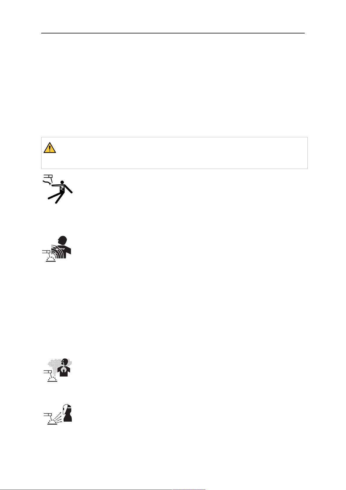
AVERTISSEMENT!
Le soudage à l'arc et la découpe sont sources de danger pour vous-même et votre
entourage. Prenez les précautions nécessaires pendant le soudage et la découpe.
DÉCHARGE ÉLECTRIQUE - Danger de mort
• Installer l'équipement et assurer sa mise à la terre conformément au
manuel d'instructions.
• Ne pas toucher des électrodes ou des pièces électriques sous tension à
main nue ou avec des gants ou des vêtements humides.
• Portez une tenue isolante et isolez la zone de travail.
• Assurez-vous de travailler dans une position sûre.
CHAMPS ÉLECTRIQUES ET MAGNÉTIQUES - Nocifs
• Les soudeurs équipés de stimulateurs cardiaques doivent consulter leur
médecin avant d'effectuer le soudage. Les CEM peuvent interférer avec
certains stimulateurs cardiaques.
• L'exposition aux CEM peut avoir d'autres effets inconnus sur la santé.
• Les soudeurs doivent suivre la procédure suivante pour minimiser
l'exposition aux CEM:
○ Acheminez l'électrode et les câbles de travail du même côté de votre
corps. Sécurisez-les avec du ruban adhésif, si possible. Ne vous
placez pas entre la torche et les câbles de travail. N'enroulez jamais
la torche ou le câble de travail autour de votre corps. Maintenez la
source d'alimentation de soudage et les câbles le plus à l'écart
possible de votre corps.
○ Connectez le câble de travail à la pièce à souder, aussi près que
possible de la zone à souder.
FUMÉES ET GAZ - Nocifs
• Éloigner le visage des fumées de soudage.
• Installer un système de ventilation ou d'évacuation au niveau de l'arc, ou
les deux, pour évacuer les émanations et les gaz de la zone respirable et
de la zone de travail en général.
RAYONS DE L'ARC – Danger pour les yeux et la peau.
0463 373 101
• Protégez-vos yeux et votre peau. Utiliser un écran de soudeur et des
verres filtrants appropriés et porter des vêtements de protection.
• Protéger les personnes voisines des effets dangereux de l’arc par des
rideaux ou des écrans protecteurs.
- 6 -
© ESAB AB 2018
1 SÉCURITÉ
BRUIT - Le niveau élevé de bruit peut altérer les facultés auditives.
Utilisez une protection d'oreilles ou toute protection auditive similaire.
PIÈCES MOBILES - peuvent provoquer des blessures
• Maintenez tous les panneaux, portes et caches fermés et fermement en
place. Assurez-vous que seules des personnes qualifiées déposent les
caches en vue de la maintenance et du dépannage, si nécessaire.
Reposez les panneaux ou les caches et fermez les portes une fois
l'entretien terminé et avant de démarrer le moteur.
• Arrêtez le moteur avant d'installer ou de brancher l'unité.
• Maintenez les mains, cheveux, vêtements amples et outils à l'écart des
pièces mobiles.
RISQUE D'INCENDIE
• Les étincelles peuvent provoquer un incendie. S'assurer qu'il n'y a pas de
matières inflammables à proximité.
• N'utilisez pas sur réservoirs fermés.
EN CAS DE DYSFONCTIONNEMENT - Faites appel à un technicien qualifié.
PROTÉGEZ-VOUS ET PROTÉGEZ VOTRE ENTOURAGE!
ATTENTION!
Ce produit est exclusivement destiné au soudage à l'arc.
AVERTISSEMENT!
N'utilisez pas le générateur pour dégeler des canalisations.
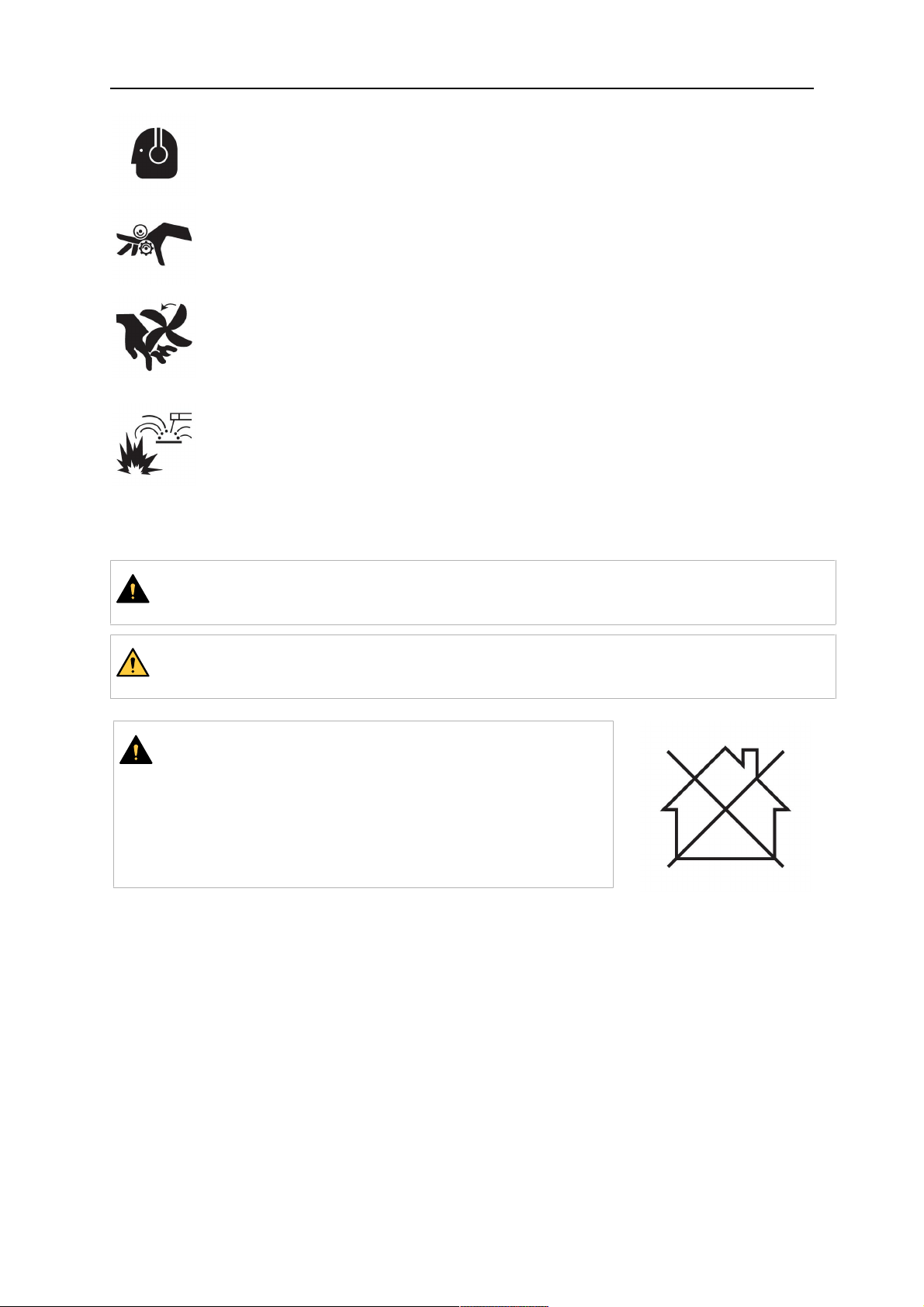
ATTENTION!
Les équipements de classeA ne sont pas conçus pour
un usage résidentiel avec une alimentation secteur à
basse tension. Dans ces lieux, garantir la compatibilité
électromagnétique des équipements de classeA
devient difficile, dû à des perturbations par conduction
et par rayonnement.
0463 373 101
- 7 -
© ESAB AB 2018
1 SÉCURITÉ
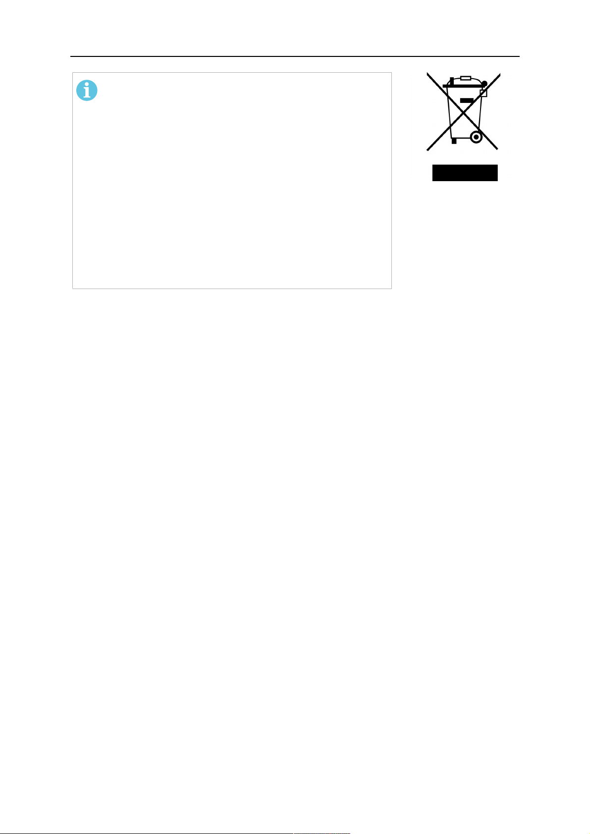
REMARQUE !
Jetez l'équipement électronique dans les centres de
recyclage agréés!
Conformément à la Directive européenne2012/19/EC
relative aux déchets d'équipements électriques et
électroniques et à sa transposition dans la législation
nationale en vigueur, les équipements électriques et/ou
électroniques parvenus en fin de vie doivent être
confiés à un centre de recyclage agréé.
En tant que responsable de l'équipement, il est de votre
responsabilité d'obtenir les informations nécessaires sur
les centres de recyclage agréés.
Pour plus d'informations, contactez votre fournisseur
ESAB le plus proche.
ESAB propose à la vente toute une gamme d'accessoires de soudage et
d'équipements de protection personnelle. Pour obtenir des informations sur les
commandes, merci de contacter votre distributeurESAB ou de consulter notre
siteWeb.
0463 373 101
- 8 -
© ESAB AB 2018

2 GARANTIE
2 GARANTIE
Nos produits font l'objet d'une inspection minutieuse avant livraison. ESAB vérifie que, à la
livraison, tous les produits sont exempts de vices de matériel et de défauts de fabrication, et
qu'ils fonctionnent conformément à l'usage prévu.
ESAB garantit l'absence de défauts de matériel et de fabrication conformément aux
prescriptions légales. Les consommables ne sont pas couverts par cette garantie.
La garantie ne couvre pas les dommages ou défauts fonctionnels résultant:
• de surcharges, d'abus ou de détournement de l'usage prévu du produit
• de collisions ou d'accidents
• de non-respect des instructions stipulées dans ces instructions d'utilisation
• d'une installation ou d'un assemblage incorrects
• d'un entretien incorrect
• d'une modification du produit d'origine
• d'influences chimiques
• d'une usure normale
ESAB n'assume aucune responsabilité autre celle liée au remplacement ou à la réparation
de pièces défectueuses.
2.1 Conditions d'utilisation prévue
1. Le produit est destiné à un usage industriel et commercial et ne doit être utilisé que
par un personnel dûment formé. Le fabricant n'est pas responsable des dommages ou
accidents résultant d'une utilisation inappropriée.
2. Le système de soudage robotisé Aristo® RT est conçu et fabriqué à la pointe de la
technologie. Il est sûr et fiable lorsqu'il est manipulé, installé et entretenu par un
personnel dûment qualifié. Les instructions d'installation, d'utilisation et d'entretien
mentionnées dans ce document doivent être observées.
3. Le système de soudage robotisé Aristo® RT peut uniquement être installé, utilisé et
entretenu par un personnel dûment qualifié. Les consignes d'installation, d'utilisation
et d'entretien spécifiées dans ce manuel doivent être observées.
4. Le système de soudage robotisé Aristo® RT doit être utilisé exclusivement aux fins
prévues par le fabricant dans le cadre de son cahier des charges et avec des
systèmes de traitement automatisés. Le type de torche doit être choisi en fonction de
l'opération de soudage à réaliser.
5. Le système de soudage robotisé Aristo® RT a été conçu pour une utilisation en tant
que système complet. L'intégration de composants d'autres fabricants au sein du
système n'est pas autorisée.
6. Les mécanismes RTKS-2 et RTKSC-2 ne doivent être utilisés qu'en tant que
mécanismes d'arrêt d'urgence, conformément à leurs spécifications techniques et
conjointement à un ensemble de câbles à bras standard RT (KS-2), Infiniturn ou Helix
(KSC-2), une bride d'adaptation ESAB, y compris des supports de torche RT (KS-2) et
une torche de soudage Aristo RT.
7. Aucune huile ni aucun liquide anti-projection ne doit être ajouté au gaz de nettoyage.
ESAB ne garantit pas la résistance chimique à ces substances. ESAB recommande
d'utiliser l'unité de pulvérisation ESAB pour appliquer la quantité minimale de liquide
anti-projection sur la torche et protéger ainsi l'environnement alentour.
8. Le produit doit être gardé au sec et à l'abri de l'humidité lors de son transport, de son
stockage et de son utilisation.
9. Le système est conçu pour des températures ambiantes comprises entre 5°C et
40°C (41°F et 104°F). Tout dépassement de ces limites exige une action spécifique.
En cas de risque de gel, utiliser un liquide de refroidissement approprié.
0463 373 101
- 9 -
© ESAB AB 2018

3 INTRODUCTION
3 INTRODUCTION
Les systèmes de torche de soudage RT sont conçus pour le soudage à l'arc entièrement
automatique en atmosphère inerte (MIG) ou en atmosphère active (MAG) à l'aide de robots.
Les systèmes se composent d'une variété de cols de torche Aristo RT conçus pour une
utilisation robotique, de supports de torche, d'ensembles de câbles optimisés pour une
utilisation robotique et de fonctions de sécurité permettant de protéger le système des
dommages en cas de collision.
Le système de soudage RT standard offre une protection contre les collisions via le
mécanisme RTKS-2, une fonction de sécurité mécanique à ressort. Il peut être remplacé par
le mécanisme RTFL-2 (en option) pour tirer parti de la fonction de détection de collision du
système de commande du robot. Le système de soudage RT standard peut être utilisé avec
différents types de câbles.
Les supports de torche RTKSC-2 et RTFLC-2 équipés d'ensembles de câbles Infiniturn ou
Helix sont conçus pour être utilisés dans les systèmes de soudage robotisés à poignet creux,
adaptés aux applications de soudage avancées. Le mécanisme de sécurité du support de
torche RTKSC-2 permet une grande déflexion élastique de la torche en cas de collision. Les
ensembles de câbles Infiniturn et Helix sont simples à poser; ils offrent un système
extrêmement fiable et des capacités de manœuvre précises.
Associés aux torches de soudage robotisées Aristo RT, largement utilisées, ces composants
forment un système extrêmement fiable et durable qui ne nécessite qu'un minimum
d'entretien.
Le manuel d'utilisation est fourni avec les supports de torche et les ensembles de câbles.
Les références de commande ESAB, les accessoires disponibles, les pièces de
rechange et les pièces d'usure sont indiqués dans la liste de pièces de rechange.
0463 373 101
- 10 -
© ESAB AB 2018

3 INTRODUCTION
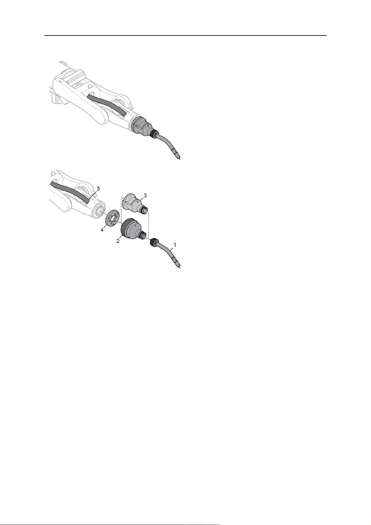
3.1 Aperçu des systèmes de torche de soudage
Système RT standard
Pour une description détaillée, se reporter à
la section correspondante du chapitre
CARACTÉRISTIQUES TECHNIQUES:
1. Col de torche
Consulter la section «Torche de
soudage».
2. Ensemble de câbles
Consulter la section «Ensembles de
câbles pour système RT standard».
3. Support de la torche
Consulter la section «Supports de
torche pour système RT standard».
4. Mécanisme de sécurité RTKS-2
Consulter la section «Mécanisme
de sécurité RTKS-2».
5. Bride intermédiaire RTFL-2
Consulter la section «Bride
intermédiaire RTFL-2».
6. Bride d'adaptation (si nécessaire)
Consulter la section «Brides
d'adaptation».
0463 373 101
- 11 -
© ESAB AB 2018
3 INTRODUCTION
Système à poignet creux
Pour une description détaillée, se reporter à
la section correspondante du chapitre
CARACTÉRISTIQUES TECHNIQUES:
1. Col de torche
Consulter la section «Torche de
soudage».
2. Support de torche RTKSC-2
Consulter la section «Support de
torche RTKSC-2 avec mécanisme
de sécurité».
3. Support de torche RTFLC-2
Consulter la section «Support de
torche rigide RTFLC-2».
4. Bride d'adaptation
Consulter la section «Brides
d'adaptation».
5. Ensemble de câbles Helix ou
Infiniturn
Consulter la section «Ensembles de
câbles pour systèmes à poignet
creux».
0463 373 101
- 12 -
© ESAB AB 2018

4 CARACTÉRISTIQUES TECHNIQUES
4 CARACTÉRISTIQUES TECHNIQUES
4.1 Col de torche de soudage
Choisir le modèle de torche en fonction de l'application de soudage. Le facteur de marche, la
méthode de refroidissement et le diamètre du fil doivent être pris en compte. Toute
augmentation des besoins, due par exemple à des pièces préchauffées ou à une réflexion
thermique dans les coins, doit être prise en considération et une torche dotée d'une réserve
de puissance nominale adaptée devra être utilisée.
Les torches de soudage RT sont destinées à être utilisées avec des sources d'alimentation
de soudage conformes à la norme CE pour les processus de soudage à l'arc de métaux en
atmosphère inerte (MIG) ou active (MAG), ou de brasage de métaux en atmosphère inerte
avec des fils ronds disponibles dans le commerce. Ne pas utiliser le chalumeau pour d'autres
processus.
Pour le soudage à l'arc pulsé de l'acier ou de l'aluminium, il convient d'utiliser la torche
RT82W refroidie par eau.
Consulter les modèles de torches disponibles ci-dessous.
Modèle de torche
Méthode de
refroidissement
RT42G Refroidissement par
gaz
Refroidissement par
gaz
Refroidissement par
gaz
Refroidissement par
gaz
RT42W Refroidissement par
eau
Refroidissement par
eau
Refroidissement par
eau
Refroidissement par
eau
RT52G Refroidissement par
gaz
Gaz de protection Valeurs nominales
CO
2
420A/60%
300A/100%
Mélange 350A/60%
250A/100%
CO
2
420A/60%
420A/100%
Mélange 350A/60%
350A/100%
CO
2
420A/60%
0463 373 101
Refroidissement par
gaz
Refroidissement par
gaz
Refroidissement par
gaz
300A/100%
Mélange 350A/60%
250A/100%
- 13 -
© ESAB AB 2018

4 CARACTÉRISTIQUES TECHNIQUES
Modèle de torche
Méthode de
refroidissement
RT52W Refroidissement par
eau
Refroidissement par
eau
Refroidissement par
eau
Refroidissement par
eau
RT62G Refroidissement par
gaz
Refroidissement par
gaz
Refroidissement par
gaz
Refroidissement par
gaz
RT62W Refroidissement par
eau
Gaz de protection Valeurs nominales
CO
2
470A/60%
470A/100%
Mélange 400A/60%
400A/100%
CO
2
500A/60%
340A/100%
Mélange 420A/60%
290A/100%
CO
2
530A/60%
Refroidissement par
eau
Refroidissement par
eau
Refroidissement par
eau
RT72G Refroidissement par
gaz
Refroidissement par
gaz
Refroidissement par
gaz
Refroidissement par
gaz
RT72W Refroidissement par
eau
Refroidissement par
eau
Refroidissement par
eau
530A/100%
Mélange 450A/60%
450A/100%
CO
2
480A/60%
320A/100%
Mélange 400A/60%
270A/100%
CO
2
480A/60%
430A/100%
Mélange 480A/60%
0463 373 101
Refroidissement par
eau
- 14 -
430A/100%
© ESAB AB 2018

4 CARACTÉRISTIQUES TECHNIQUES
Modèle de torche
Méthode de
refroidissement
RT82W Refroidissement par
Gaz de protection Valeurs nominales
CO
2
600A/60%
eau
Refroidissement par
600A/100%
eau
Refroidissement par
Mélange 550A/60%
eau
Refroidissement par
550A/100%
eau
Les valeurs relatives aux spécifications nominales et au facteur de marche sont valables
pour un cycle de 10minutes.
Les données techniques sont valables pour une application standardisée utilisant les pièces
d'usure/de rechange standard. Les spécifications nominales de la torche sont réduites
lorsque le mode de transfert de métal à arc pulsé est utilisé.
Plages de températures Stockage: -15-50°C (5-122°F)
Fonctionnement: 5-40°C (41-104°F)
Gaz de nettoyage 10bar max., flexible de gaz distinct
Poids total (col de torche, mécanisme de
Environ 5kg
sécurité, support de torche et ensemble de
câbles de 1m)
4.2 Tension nominale
Tension/intensité max. autorisée
Système de torche de soudage complet 141V (valeur de crête pour le soudage)
Circuit de commande de sécurité RTKS-2
Bouton-poussoir RTKS-2
Circuit de commande de sécurité RTKSC-2 48 V
Utilisation de la fonction de détection de
tuyère avec un ensemble de câbles standard
Utilisation de la fonction de détection de
tuyère avec des ensembles de câbles Helix
ou Infiniturn
Les spécifications indiquées se réfèrent à un cas d'utilisation normalisé.
24V/1A
48V/0,1A
50V/5A
(Charge max. autorisée pendant 1minute au
courant nominal)
50V/5A
(Charge max. autorisée pendant 1minute au
courant nominal)
Pour connaître les valeurs nominales des ensembles de câbles, consulter la section
«Ensembles de câbles».
4.2.1 Limites du circuit de refroidissement
Valeurs valables uniquement pour la version refroidie par eau.
Débit d'eau minimal: 1,0l/min (1,1qt/min)
Pression d'eau minimale: 2,5bar (36,3PSI)
Pression d'eau maximale: 3,5bar (50,8PSI)
0463 373 101
- 15 -
© ESAB AB 2018
4 CARACTÉRISTIQUES TECHNIQUES
Température d'entrée: 40°C (104°F) max.
Température de retour: 60°C (140°F) max.
Capacité de refroidissement: 1000W min., en fonction de l'application
ATTENTION!
Des températures de retour supérieures à 60°C (140°F) pourraient endommager
ou détruire l'ensemble de câbles.
4.3 Support de la torche
Le type de support de torche requis dépend de la conception du système de torche de
soudage RT et du choix des dispositifs de sécurité; consulter la section «Aperçu des
systèmes de torche de soudage».
Composants Poids approximatif
Support de torche (pour système standard) 0,43 kg
Mécanisme de sécurité RTKS-2 (pour
0,85 kg
système standard)
Bride intermédiaire RTFL-2 (pour système
0,35 kg
standard)
Support de torche RTKSC-2 (pour système à
1,90 kg
poignet creux)
Support de torche rigide RTFLC-2 (pour
1,22 kg
système à poignet creux)
Torche de soudage pour robot 0,66 kg
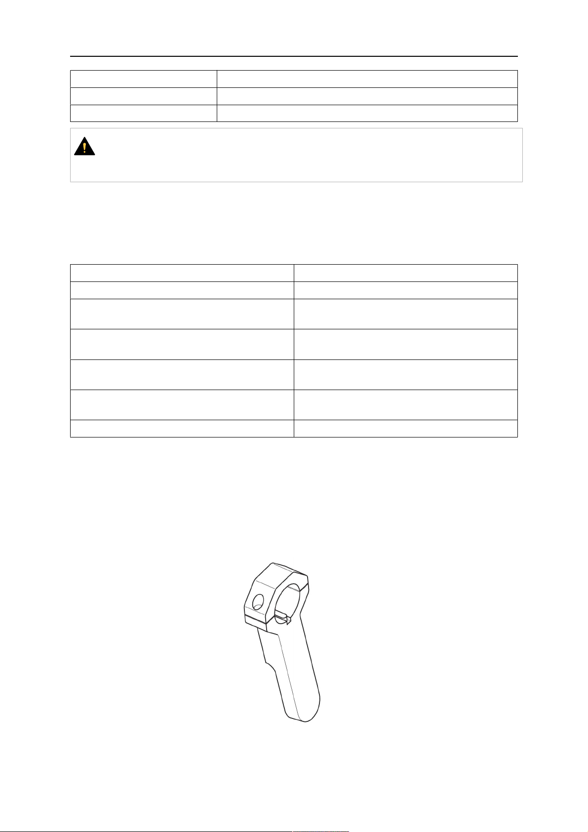
4.3.1 Supports de torche pour système RT standard
Sur les systèmes RT standard, le support de torche est installé sur le mécanisme de sécurité
RTKS-2 (ou sur la bride intermédiaire RTFL-2), en serrant l'ensemble de câbles et le col de
torche raccordé.
Choisir le support de torche en fonction du type et de la géométrie de la torche. Différents
types de supports peuvent être utilisés. Consulter la liste de pièces de rechange pour
connaître les supports de torche disponibles pour le système RT standard.
Support de torche pour robots à bras standard
0463 373 101
- 16 -
© ESAB AB 2018
4 CARACTÉRISTIQUES TECHNIQUES
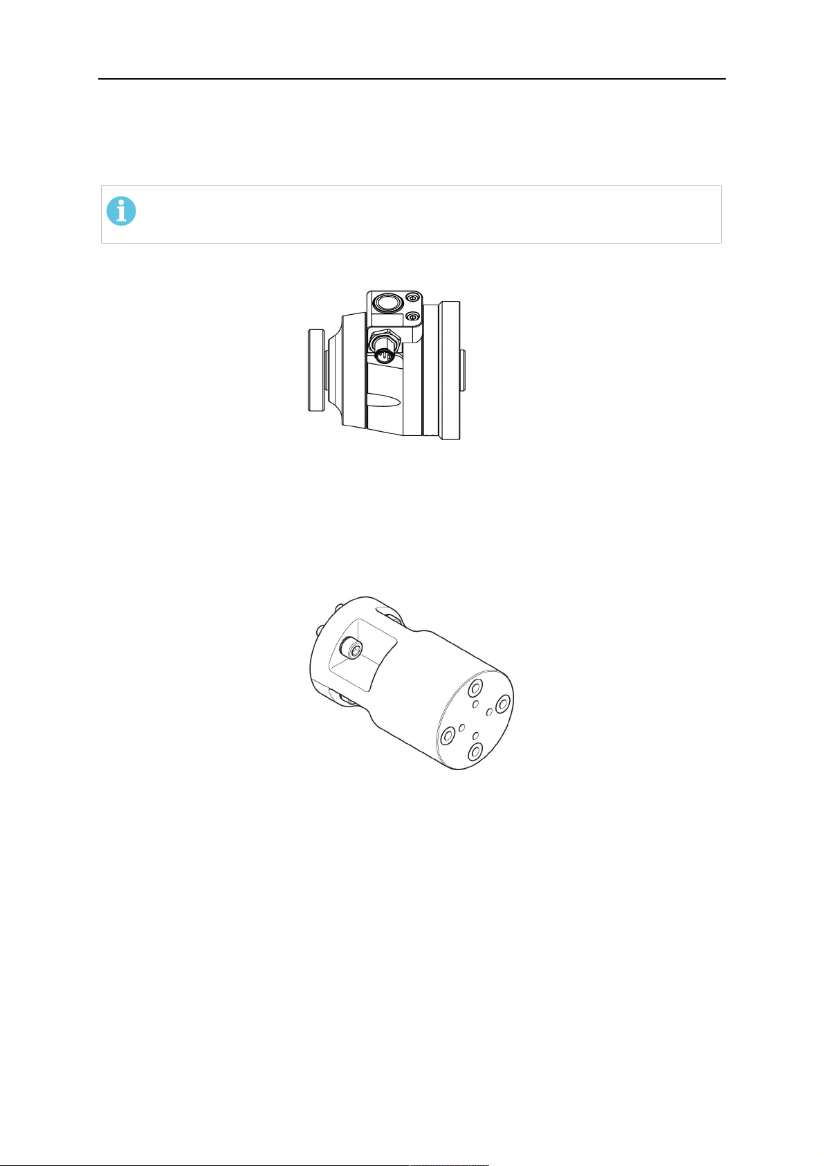
4.3.1.1 Mécanisme de sécurité RTKS-2
Le mécanisme de sécurité RTKS-2 est un dispositif à ressort qui protège le robot et le
système de torche en cas de collision.
REMARQUE !
Ne pas démonter le mécanisme RTKS-2.
4.3.1.2 Bride intermédiaire RTFL-2
La bride intermédiaire rigide RTFL-2 peut être utilisée à la place du mécanisme RTKS-2 si
le robot est équipé d'un système de détection de collision électronique.
4.3.2 Supports de torche pour système à poignet creux
Sur le système à poignet creux, les cols de torche de soudage Aristo RT sont raccordés au
support de torche KSC-2 ou FLC-2.
Le support de torche RTKSC-2 permet la déflexion élastique de la torche en cas de collision.
En même temps, un contact électrique s'ouvre, signalant l'arrêt de la commande du robot.
Suite à la réinitialisation de l'erreur, la géométrie initiale et le point central de l'outil (TCP) de
la torche sont atteints avec une grande précision. Le système fonctionne uniquement
mécaniquement et est monté sur ressort.
Le support de torche RTFLC-2 ne présente pas de fonction de sécurité intégrée.
0463 373 101
- 17 -
© ESAB AB 2018
4 CARACTÉRISTIQUES TECHNIQUES
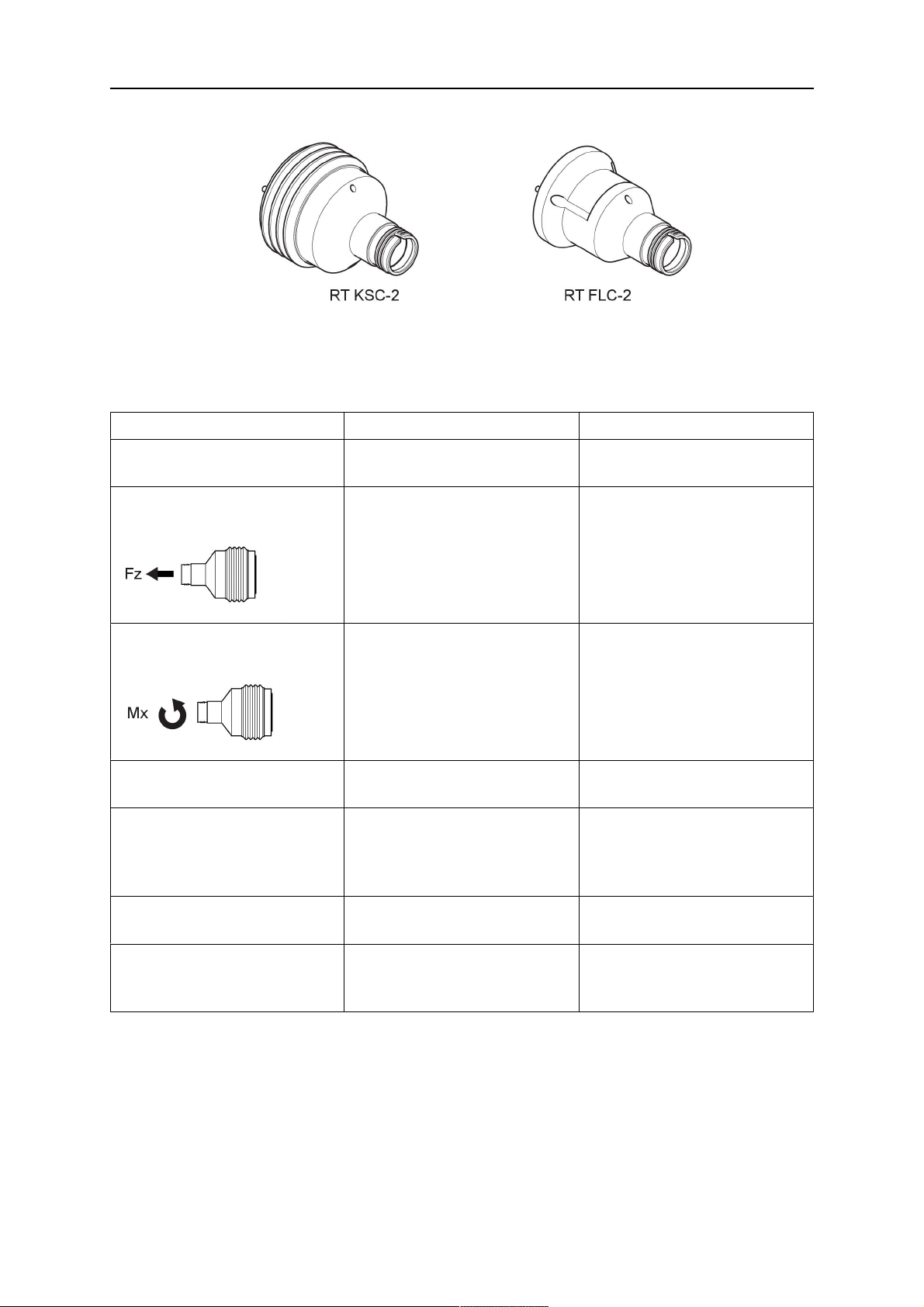
Sur les systèmes à poignet creux, le support RTKSC-2 G/W (ou RTFLC-2 G/W) est
recommandé. Ce support de torche peut être utilisé avec les torches refroidies par gaz et par
eau de la série Aristo RT.
RTKSC-2 G/W RTFLC-2 G/W
Principe de fonctionnement
Mécanique Non applicable (support
du mécanisme de sécurité
Force de déclenchement
650 N Non applicable (support
axial (Fz)
Couple de déclenchement sur
24 Nm Non applicable (support
l'axe transversal (Mx)
Réinitialisation après
Automatique Non applicable (support
déclenchement
Répétabilité Latérale ±0,1mm au niveau
du point central de l'outil
d'une torche standard Aristo
RT
rigide)
rigide)
rigide)
rigide)
Non applicable (support
rigide)
Déflexion max. Environ ±8° Non applicable (support
rigide)
Interrupteur de sécurité Normalement fermé
Charge électrique max.
Non applicable (support
rigide)
48V/1A
0463 373 101
- 18 -
© ESAB AB 2018

4 CARACTÉRISTIQUES TECHNIQUES
Circuit de commande
électrique de la fonction de
détection de tuyère
Valeurs nominales:
• Sur les ensembles de
câbles Helix:
50VCC/5A max.,
1minute max.
Suite à la détection du
contact, débrancher
rapidement la tension de
détection.
• Sur les ensembles de
câbles Infiniturn, la
fonction de détection de
tuyère est limitée.
Valeurs nominales:
• Sur les ensembles de
câbles Helix:
50VCC/5A max.,
1minute max.
• Sur les ensembles de
câbles Infiniturn:
50VCC/1A max.,
1minute max.
Suite à la détection du
contact, débrancher
rapidement la tension de
détection.
Contacter ESAB pour
étudier plus en détail les
solutions possibles pour
votre application.
Tension nominale Tension maximale autorisée
pour le circuit de commande
de sécurité: 48V.
4.3.2.1 Support de torche RTKSC-2 G/W avec mécanisme de sécurité
ArticleDescription Fonction
1 Support de col de torche Interface de torche Aristo RT
2 Couvercle RTKSC-2 Ensemble avec interfaces de câble et de torche
0463 373 101
- 19 -
© ESAB AB 2018

4 CARACTÉRISTIQUES TECHNIQUES
ArticleDescription Fonction
3 Gaine caoutchoutée Protection du mécanisme de sécurité
4 Corps principal RTKSC-2 Permet une déflexion mécanique en cas de collision
5 Bride d'adaptation Interface d'isolation au niveau du poignet du robot
(doit être adaptée au robot spécifique)
6 Broche d'indexage Pour un alignement précis sur la bride d'adaptation
7 Connecteur du câble de
commande
Raccordement électrique du signal de collision et de
la fonction de détection de tuyère
8 Microrupteur Capteur de détection de collision
4.3.2.2 Support de torche rigide RTFLC-2 G/W
ArticleDescription Fonction
1 Support de col de torche Interface de torche Aristo RT
2 Couvercle RTFLC-2 Ensemble avec interfaces de câble et de torche
3 Corps principal RTFLC-2 Permet une déflexion mécanique en cas de collision
4 Broche d'indexage Pour un alignement précis sur la bride d'adaptation
5 Bride d'adaptation Interface d'isolation au niveau du poignet du robot
(doit être adaptée au robot spécifique)
6 Connecteur du câble de
commande (3pôles)
0463 373 101
Raccordement électrique de la fonction de détection
de tuyère (le cas échéant)
- 20 -
© ESAB AB 2018
4 CARACTÉRISTIQUES TECHNIQUES
4.4 Brides d'adaptation
Choisir la bride d'adaptation requise pour l'installation sur le bras du robot en fonction du
type de robot. Des brides d'adaptation sont disponibles pour tous les systèmes standard et à
poignet creux adaptés; consulter la liste de pièces de rechange.
4.5 Ensembles de câbles
Le raccordement au dévidoir s'effectue par l'ensemble de câbles; les versions disponibles
dépendent principalement de la conception du système et du moyen de refroidissement (gaz
ou eau); consulter la liste de pièces de rechange.
Les spécifications sont valables pour des câbles d'une longueur de 1 à 5 m.
Ensemble de câbles
Infiniturn Helix
standard
Valeur nominale
(cycle de 10min)
Refroidissement par
gaz (gaz mélangé)
Valeur nominale
(cycle de 10min)
Refroidissement par
500A/facteur de
marche de 60% max.
350A/facteur de
marche de 100%
max.
600A/facteur de
marche de 100%
max.
400A/facteur de
marche de 60% max.
320A/facteur de
marche de 100%
max.
550A/facteur de
marche de 100%
max.
400A/facteur de
marche de 60% max.
320A/facteur de
marche de 100%
max.
550A/facteur de
marche de 100%
max.
eau
Plage de rotation Rotation limitée Rotation illimitée ±270° depuis la
position neutre
Poids
Refroidissement par
1,2m de long:
2,35 kg
1,0m de long:
2,0 kg
1,0m de long:
2,0 kg
gaz
Poids
Refroidissement par
1,2m de long:
2,35 kg
1,0m de long:
2,0 kg
1,0m de long:
2,0 kg
eau
4.5.1 Ensembles de câbles pour système RT standard
0463 373 101
- 21 -
© ESAB AB 2018

4 CARACTÉRISTIQUES TECHNIQUES
Broches de connecteur Burndy
A. Tuyère de gaz à
auto-détection
C. Capteur de collision
F. 0V
G. Tension du moteur +
H. Tension du moteur -
D. Capteur de collision
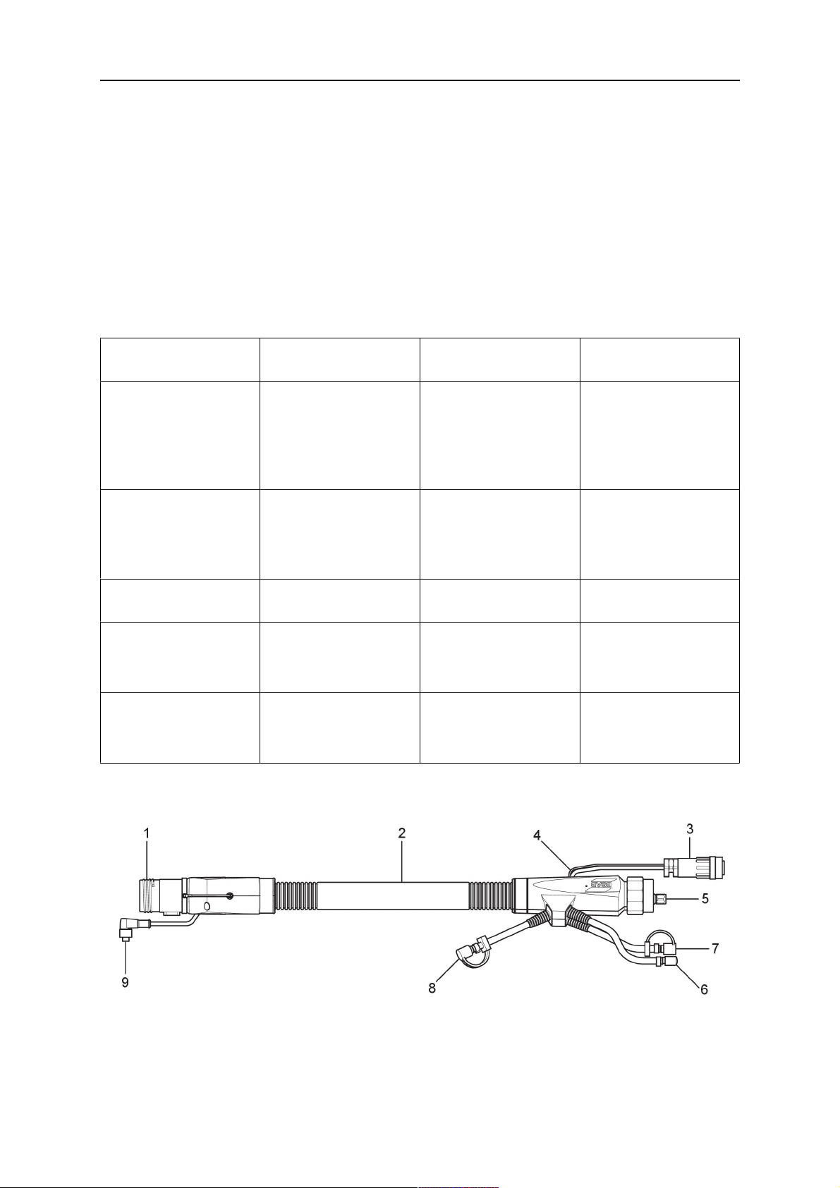
E. Marche fractionnée
ArticleDescription Fonction
1 Bride de support de col Interface de torche
2 Couvercle de protection Protège l'ensemble de câbles des dommages
3 Connecteur Burndy, 12pôles Raccordement électrique entre le mécanisme de
sécurité et le dévidoir
4 Câble de commande Pour KS-2 (mécanisme de sécurité et
bouton-poussoir)
5 Connecteur EURO Raccordement du dévidoir
6 Flexible de nettoyage
(capuchon noir)
7 Entrée d'eau (bouchon bleu)
8 Retour d'eau (bouchon rouge)
Pour le nettoyage de la torche à l'air comprimé
après le cycle de nettoyage
Entrée d'eau pour le refroidissement de la torche
Retour d'eau chauffée de la torche
1)
1)
9 Fiche de câble de commande
pour le mécanisme de sécurité
Raccordement électrique avec le mécanisme
RTKS-2 pour le signal de sécurité et la fonction de
détection de tuyère
1)
Pour les systèmes de torche à refroidissement par eau uniquement
4.5.2 Ensembles de câbles pour systèmes à poignet creux
L'ensemble de câbles Infiniturn permet une rotation illimitée de la torche dans les deux sens.
En même temps, le liquide de refroidissement, le gaz de protection, l'air de nettoyage, la
puissance de soudage et le signal du mécanisme de sécurité sont transférés.
L'ensemble de câbles Helix est conçu pour une plage de rotation de ±270° depuis la position
neutre. Il peut être utilisé pour les tâches de soudage qui ne nécessitent pas de rotation
illimitée.
Les ensembles de câbles Infiniturn sont disponibles en versions refroidies par gaz et par
eau. Les ensembles de câbles Helix peuvent être utilisés universellement pour les
applications refroidies par gaz ou par eau.
REMARQUE !
Ne pas raccorder un ensemble de câbles Helix fonctionnant avec un col de torche
refroidi par gaz à un système de refroidissement par eau.
0463 373 101
- 22 -
© ESAB AB 2018

4 CARACTÉRISTIQUES TECHNIQUES
ArticleDescription Fonction
1 Bride Interface de support de torche RTKSC-2 /
RTFLC-2
2 Broche d'indexage Assure la bonne orientation de l'accouplement
3 Fiche de câble de commande Raccordement électrique au mécanisme RTKSC-2
pour le signal de sécurité et la fonction de détection
de tuyère (le cas échéant)
4 Connecteur EURO Raccordement du dévidoir
5 Câble de commande Raccordement électrique du signal de sécurité
(provenant du mécanisme RTKSC-2) et de la
fonction de détection de tuyère (la fonction de
détection de tuyère est fournie de série sur les
câbles Helix, mais pas sur les câbles Infiniturn)
6 Retour d'eau (bouchon rouge) Retour d'eau chauffée de la torche
7 Entrée d'eau (bouchon bleu) Entrée d'eau pour le refroidissement de la torche
8 Flexible de nettoyage
(capuchon noir)
Pour le nettoyage de la torche à l'air comprimé
après soudage.
9 Accouplement de produit Accouplement rotatif illimité avec transfert de produit
10 Couvercle de protection Protège l'ensemble de câbles des dommages
0463 373 101
- 23 -
© ESAB AB 2018

5 INSTALLATION
5 INSTALLATION
AVERTISSEMENT!
For your own safety, make sure that the robot is either in standby or power-less
state before doing maintenance work in the moving radius of the robot.
Follow the assembly instructions exactly. Pay attention during assembly that the cables are
not damaged. Damaged cables can lead to a short circuit, which may damage the electronics
of the robot or the welding torch.
Use only original ESAB components that have been specially developed for this purpose.
Only then the correct functioning of the whole welding torch system can be guaranteed.
5.1 RTKS-2 standard arm installation
5.1.1 RTKS-2 safety-off mechanism
1. Dismount the insulation flange (10) from the RTKS-2 (11) by removing the screws
(12).
2. Position the insulation flange (10) with the index pin on the robot arm and fix it with the
screws (20) included.
The insulation flange (10) is directly compatible with robots with tool flange according
to DIN ISO 9409-1-A40 (diameter 40mm, 4×M6). If the insulation flange (10) does
not fit, use an adapter flange (21).
REMARQUE !
Ensure that the index pin is located correctly. The maximum torque of 1.2Nm
(10.5in.lb) must be observed for the fastening of the adapter flange screws.
Prevent self-loosening of the screws by using suitable thread locking
measures.
3. Mount the RTKS-2 the back on the insulation flange (10).
0463 373 101
- 24 -
© ESAB AB 2018

5 INSTALLATION
4. Position the mount on the RTKS-2 and carefully insert the cylindrical pins (14) into the
holes provided. Take the position of the torch into account. Two mounting positions
may be potentially possible.
5. Screw the mount evenly using the enclosed cylinder screws with hexagon socket (12).
REMARQUE !
The maximum tightening torque for the cylinder screw (5) is 6Nm (53in.lb)
and the property class category is 8.8.
12 - Cylinder screw with hexagon socket
M6DIN912 (length of the screw depending
on the torch mount)
14 - Cylindrical pins Ø4×20
5.1.1.1 Torch installation with adjustable mount
Torch mounts with a central clamping assembly can only be fastened on the journal of the
mounting flange. For this, the mounting flange must be fastened first.
1. If applicable, carefully press the cylindrical pins (1) into the corresponding holes in the
mounting flange. The pins should protrude by approximately 5 mm (0.2 in.).
2. Position the mount on the safety-off mechanism RTKS-2 and carefully insert the
cylindrical pins (1) into the holes provided. In doing so, take the later position of the
torch into account. Two mounting positions may be potentially possible.
3. Then screw down the mounting flange evenly using the enclosed cylinder screws with
hexagon socket (2).
REMARQUE !
The maximum tightening torque for the cylinder screw (2) is 7.1 Nm (62.8
in.lb) and the property class category is 8.8.
0463 373 101
- 25 -
© ESAB AB 2018

5 INSTALLATION
4. Unscrew the axial cylinder screw with hexagon socket (4) out of the mounting flange
together with the washer (3).
1 - Cylindrical pins Ø4×14 3 - Washer Ø9 mm
2 - Cylinder screw with hexagon socket
M6×16
4 - Axial cylinder screw with hexagon
socket M8×16
5. Place the torch mount (5) onto the journal (6) of the mounting flange, paying attention
while doing so to the exact alignment of the feather key (7) and the corresponding
groove (7a).
6. Insert the clamping mandrel (8) into the lateral hole (see illustration) and position it so
that the mating surfaces (9a) of the clamping mandrel rest on the mating surface (9) of
the journal.
0463 373 101
- 26 -
© ESAB AB 2018

5 INSTALLATION
7. Fix the clamping mandrel from the opposite side using the M6 cylinder screw with
hexagon socket (10) and the Ø22 mm washer (11).
8. Screw the axial cylinder screw (4) with the Ø9 mm washer (3) into the mounting flange
and tighten firmly.
3 - Washer Ø9 mm 8 - Clamping mandrel
4 - Axial cylinder screw with hexagon
9 - Mating surface of mounting flange
socket M8×16
5 - Torch mount 9a - Mating surfaces of clamping mandrel
6 - Mounting flange journal 10 - Cylinder screw with hexagon socket
M6×30
7 Feather key 11 - Washer Ø22×6.4 mm
7a - Groove for feather key
5.1.2 Standard arm cable assembly for KS-2 and FL-2
The cable assembly must be aligned to the intended use in length and design. The type of
cooling for the torch and the cable assembly must be the same (either gas or water cooled
respectively). In order to prevent damage to the torch system and other components, it is
imperative to observe the following instructions.
0463 373 101
- 27 -
© ESAB AB 2018

5 INSTALLATION
ATTENTION!
• Coordinate the length and design of the cable assembly to suit the range of
action of the robot.
• Do not bend, compress or overstretch the cable assembly.
• Fix the cable assembly such that is can be moved freely and cannot become
entangled.
• Any additional holding devices possibly installed, for example a balancer,
must not crush or bend the cable assembly.
• Extreme turning movements must be avoided in which the cable assembly
may become twisted.
• Chafing on the robot or other objects must be excluded.
1. Unscrew the cylinder screws (1) and lift off the top section (2) of the torch mount.
2. Insert the feather key (4) into the recess of the neck support flange (3) from below.
3. Align the neck support flange (3) including the feather key (4) to the groove (5) of the
torch mount and push into the groove right up to the stop of the flange.
4. Hold the cable assembly in this position and simultaneously place the top section (2)
back onto the torch mount. First screw both cylinder screws (1) loosely in to about the
same length, then tighten alternately. The top section (2) of the mount should have an
even gap to the bottom section.
The front part of the cable assembly is directly clamped into the torch mount (see
illustration below).
1 - Cylinder screws 4 - Feather key
2 - Torch mount top section 5 - Groove for feather key
3 - Neck support flange
5.1.3 RTKS-2 wire feeder connection
In order to be able to create the connection, the cable assembly must be mounted as
described in the "Installing the cable assembly" section and equipped following "Installing the
wire guide" section. Only then can the central and media connection take place. Proceed as
described below:
0463 373 101
- 28 -
© ESAB AB 2018

5 INSTALLATION
1. Connect the central connector of the cable assembly (2) to the wire feeder cabinet
socket. Tighten the central connector sleeve nut fingertight. Do not use tools.
1 - Burndy Connector 4 - Return of heated water (red cap)
2 - EURO central connector 5 - Return of heated water (red cap)
3 - Air blow-out 6 - Main Wire feeder
2. For water cooled systems. Connect the water hoses to the cooling circuit. The end of
the hose marked blue (4) is connected to the water outlet, and the end marked red (5)
is connected to the water return.
3. Connect the blow-out line (3) to the corresponding connection of the feeder.
4. Connect the Burndy Connector to the wire feeder. (1) to the feeder. See section
"Electrical connections".
REMARQUE !
All hoses and the control line must be installed so they can not bend or get
damaged!
5.1.4 RTKS-2 electrical connections
5.1.4.1 RTKS-2 safety-off mechanism connection
The switch for the safety-off functionality RTKS-2 is connected through the control cable,
see (3) in the illustration below. This connects to the RTKS-2 unit via the 4-pole plug (4) that
contains circuits for the push-button (6) and the safety-off signal (7).
If a collision is detected, the control circuit for the safety-off signal (7), which is normally
closed, will be interrupted.
Rating of the control circuit: max. 48 V / 1 A
0463 373 101
- 29 -
© ESAB AB 2018

5 INSTALLATION
2 - Burndy connector 5 - RTKS-2 connector for control cable plug
4 - Control cable plug
Broches de connecteur Burndy
A. Tuyère de gaz à
auto-détection
C. Capteur de collision
F. 0V
G. Tension du moteur +
H. Tension du moteur -
D. Capteur de collision
E. Marche fractionnée
If the robot control provides a control circuit for nozzle sense functionality, the connection is
accomplished with a 1-wire connection.
Rating of the control circuit: max 50 V / 5 A.
DANGER!
If the nozzle sense function is not being used, the open end of the control cable on
the power source connection side must be properly isolated in order to avoid short
circuits. During certain problems on the torch head, the full welding potential may be
present on this cable.
ATTENTION!
After detection of contact (gas nozzle on work piece), quickly reduce or cut off the
maximum current in the nozzle sense circuit in order to avoid overloading of the
system.
Allowed load max. 1 minute at the rated nominal current.
5.1.5 RTKS-2 Torch installation
Continue according to section "Torch installation".
0463 373 101
- 30 -
© ESAB AB 2018

5 INSTALLATION
5.2 RTFL-2 standard arm installation
5.2.1 RTFL-2 rigid mount
1. Position the RT FL-2 (2) with the index pin on the robot arm and fix it with the hexagon
socket screw included.
The FL-2 is directly compatible with robots with tool flange according to DIN ISO
9409-1-A40 (diameter 40mm, 4×M6). If the rigid mount does not fit, use an adapter
flange (3).
REMARQUE !
Ensure that the index pin is located correctly. The maximum torque of 1.2Nm
(10.5in.lb) must be observed for the fastening of the adapter flange screws.
Prevent self-loosening of the screws by using suitable thread locking
measures.
2. Install torch mount (1). Only torch mounts having a hole pattern equivalent with the
mounting surface may be attached. If necessary, carefully press the cylindrical pins (4)
into the corresponding holes in the bracket. The pins should protrude by
approximately 5mm (0.2in.). Position the torch mount on the RTFL-2 (2) and
carefully insert the cylindrical pins (4) into the holes provided. Take the position of the
torch into account. Two mounting positions may be potentially possible.
3. Screw the mount evenly using the enclosed cylinder screws with hexagon socket (5).
REMARQUE !
The maximum tightening torque for the cylinder screw (5) is 6Nm (53in.lb)
and the property class category is 8.8.
0463 373 101
- 31 -
© ESAB AB 2018

5 INSTALLATION
4 - Cylindrical pins Ø4×20
5 - Cylinder screw with hexagon socket M6
DIN 912 (length of the screw depending on
the torch mount)
Side view
Torch installation with adjustable mount
Torch mounts with a central clamping assembly can only be fastened on the journal of the
mounting flange. For this, the mounting flange must be fastened first.
1. If applicable, carefully press the cylindrical pins (1) into the corresponding holes in the
mounting flange. Avoid the formation of burrs. The pins should protrude by
approximately 5 mm (0.2 in.).
2. Position the mount on the RTFL-2 and carefully insert the cylindrical pins (1) into the
holes provided. In doing so, take the later position of the torch into account. Two
mounting positions may be potentially possible.
3. Then screw down the mounting flange evenly using the enclosed cylinder screws with
hexagon socket (2).
REMARQUE !
The maximum tightening torque for the cylinder screw (2) is 7.1 Nm (62.8
in.lb) and the property class category is 8.8.
4. Unscrew the axial cylinder screw with hexagon socket (4) out of the mounting flange
together with the washer (3).
1 - Cylindrical pins Ø4×14 3 - Washer Ø9 mm
2 - Cylinder screw with hexagon socket
M6×16
4 - Axial cylinder screw with hexagon
socket M8×16
5. Place the torch mount (5) onto the journal (6) of the mounting flange, paying attention
while doing so to the exact alignment of the feather key (7) and the corresponding
groove (7a).
0463 373 101
- 32 -
© ESAB AB 2018

5 INSTALLATION
6. Insert the clamping mandrel (8) into the lateral hole (see illustration) and position it so
that the mating surfaces (9a) of the clamping mandrel rest on the mating surface (9) of
the journal.
7. Fix the clamping mandrel from the opposite side using the M6 cylinder screw with
hexagon socket (10) and the Ø22 mm washer (11).
8. Screw the axial cylinder screw (4) with the Ø9 mm washer (3) into the mounting flange
and tighten firmly.
3 - Washer Ø9 mm 8 - Clamping mandrel
4 - Axial cylinder screw with hexagon
9 - Mating surface of mounting flange
socket M8×16
5 - Torch mount 9a - Mating surfaces of clamping mandrel
6 - Mounting flange journal 10 - Cylinder screw with hexagon socket
M6×30
7 - Feather key 11 - Washer Ø22×6.4 mm
7a - Groove for feather key
5.2.2 RTFL-2 torch installation
Continue according to section "Torch installation".
5.3 RTKSC-2 hollow wrist system installation
5.3.1 RTKSC-2 mount with safety off mechanism
ATTENTION!
For hollow wrist systems make sure that the clear space around the robot is at least
Ø45 mm (1.8 in.) around the wrist and 50 mm (2.0 in.) near the wire feeder.
0463 373 101
- 33 -
© ESAB AB 2018

5 INSTALLATION
1. Remove the three screws (2) from the front cover (3) of the torch mount and carefully
pull the cover off the RTKSC-2 main body (5). Take care not to damage the micro
switches installed inside the assembly.
1 - Hexagon wrench 4 mm 4 - Rubber boot
2 - 3× M5×12 screws 5 - RT KSC-2 main body
3 - RT KSC-2 front cover
1. Pull off the rubber boot (4) from the RTKSC-2 main body (5) to the front.
2. Now position the RTKSC-2 main body (5) on the adapter flange (7) so that the index
pin is correctly seated. Attach with the screws (6) enclosed.
3. Reinstall the rubber boot (4) on the RTKSC-2 main body (5) and make sure it is
correctly located in the grooves on the front and back flange.
4. Istall the adapter flange (7) on the robot.
Fastening torque max. 2.2 Nm (19.5 in.lb).
1 - Hexagon wrench 4 mm 3 - 3× M5×12 hexagon socket screws
2 - Rubber boot 4 - Adapter flange
5.3.2 Mounting the cable assembly
REMARQUE !
In order to adjust the wire feeder position to the cable assembly length, it must be
mounted on an adjustable support with a possible movement of ±2-3cm (±1in.) to
the back and to the front. The length of the cable assembly must be determined
from the centred mounting position of the wire feeder.
1. Move the robot arm into a completely straight position, see illustration below. Make
sure that (1) axis 6 (rotation around the torch axis) is in 0° position.
2. Move the feeder (3) completely to the back in order to create space for inserting the
cable assembly. If it is not possible to move the feeder sufficiently, it should be
removed from the robot.
0463 373 101
- 34 -
© ESAB AB 2018

5 INSTALLATION
3. Insert the cable assembly with the coupling (2) first into the robot arm and feed it
through the robot wrist.
4. The feeder should only be installed again after the correct mounting position with
respect to the cable length has been determined. (See section "Installing the cable
assembly").
ATTENTION!
Axis 6 must be in 0° position.
5.3.2.1 RTKSC-2 feeder cabinet connections
When installed for the first time, the position of the wire feeder cabinet must be adjusted to
the length of the cable assembly. First, the robot arm must be fully extended (straight).
ATTENTION!
As long as the correct position of the feeder corresponding to the length of the cable
assembly has not been determined, be careful when moving the robot arm and
avoid overstretching the cable. It is helpful to loosen the positioning screws of the
feeder before moving the robot arm to allow the feeder to follow the cable assembly.
0463 373 101
- 35 -
© ESAB AB 2018

5 INSTALLATION
1. Loosen the sliding mechanism of the wire feeder and connect the cable assembly.
2. Now adjust the position of the wire feeder to suit the length of the Infiniturn or Helix
cable, as indicated with "A" in the illustration below.
ATTENTION!
When adjusting the position of the feeder cabinet, make sure that the cable
assembly is not under stress when the robot arm is in stretched-out position.
It is normal for the cable assembly to sag slightly, it should never be taut.
3. Before securing the wire feeder in its permanent position, ensure that the Euro
connectors are tightly connected. Then turn the torch mount down and up again
(rotating on the axis 5), in order not to tighten the cable assembly too much against
the feeder (see illustration above). Once this is done, tighten the feeder in that
position.
4. For water cooled systems, connect the water lines to the cooling circuit. See section
"Cable assemblies for hollow wrist systems" in the TECHNICAL DATA chapter for
indications.
The hose with the blue rubber cap is for cooling water to the torch, the hose with the
red rubber cap returns the heated water. Make sure the hoses will not kink or get
otherwise blocked.
REMARQUE !
A Helix cable assembly used for a gas cooled system must not be connected
to a cooling circuit. As the water connections are not needed, they may be cut
off.
5. Connect the blow-out hose (black rubber cap) to the corresponding outlet of the wire
feeder.
REMARQUE !
If the blow-out function is not used, the blow-out hose must be sealed with the
rubber cap enclosed. With Infiniturn systems, the blow-out air must be
supplied to the corresponding connection hose, if it is not permitted to connect
blow-out air to the shield gas connection!
6. Install the necessary plug on the control cable and connect it to the safety off circuit
interface of the wire feeder (see section "Electrical connections").
0463 373 101
- 36 -
© ESAB AB 2018

5 INSTALLATION
5.3.3 RTKSC-2 cable assembly
The cable assembly must be aligned to the intended use in length and design. The type of
cooling for the torch and the cable assembly must be the same (either gas or water cooled
respectively). In order to prevent damage to the torch system and other components, it is
imperative to observe the following instructions.
ATTENTION!
• Coordinate the length and design of the cable assembly to suit the range of
action of the robot.
• Do not bend, compress or overstretch the cable assembly.
• Fix the cable assembly such that is can be moved freely and cannot become
entangled.
• Any additional holding devices possibly installed, for example a balancer,
must not crush or bend the cable assembly.
• Extreme turning movements must be avoided in which the cable assembly
may become twisted.
• Chafing on the robot or other objects must be excluded.
5.3.3.1 RTKSC-2 cable assembly installation
REMARQUE !
For some robots, it may be possible to deviate from this order, and first connect the
cable assembly to the RTKSC-2, then thread the cable from the front through the
robot arm. If in doubt, follow the suggested order.
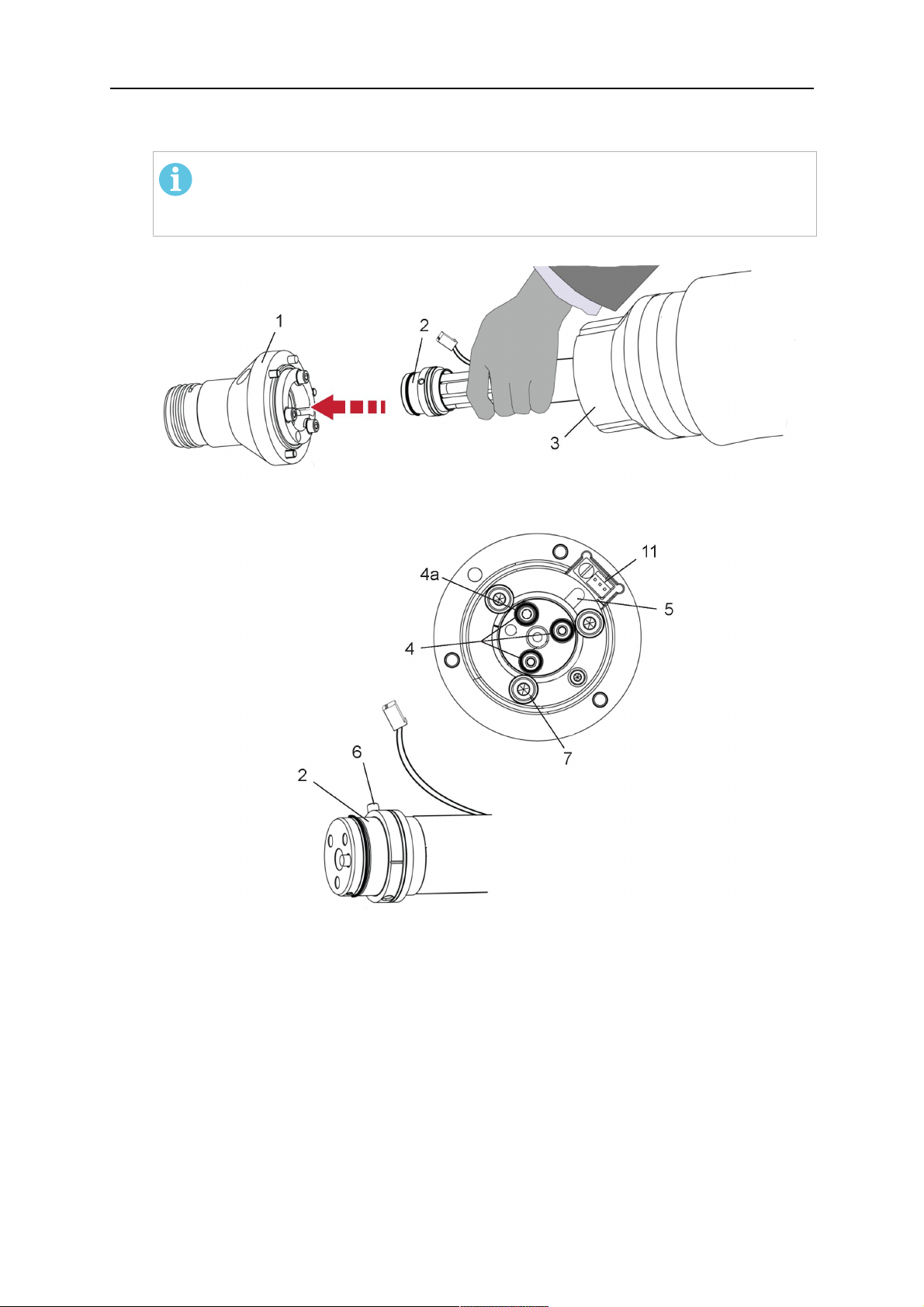
1. Loosen the three screws (7) with the associated washers and remove them from the
RTKSC-2 cover (1). See illustration below.
2. Install the supplied O-rings (4) into the grooves in the cover (1).
3. Pull the cable assembly approximately 15 cm (6 in.) from the main body (3).
0463 373 101
- 37 -
© ESAB AB 2018

5 INSTALLATION
4. Insert the coupling (2) into the socket of the cover (1) as shown. Align the index pin (6)
with the index hole (5) in the main body and insert completely.
REMARQUE !
Make sure that the position of the O-rings are not shifted by the index pin
during the assembly.
1 - RTKSC-2 cover 5 - Index hole
2 - Coupling 6 - Index pin
3 - RTKSC-2 main body 7 - 3× M5×35 screws
4 - 3× O-ring for water cooled systems 11 - Control cable connector
5. Insert the three screws (7) with the associated washers (8) and tighten gently with the
enclosed hexagonal wrench, see below illustration.
Fastening torque approximately 2 Nm (18 in.lb).
0463 373 101
- 38 -
© ESAB AB 2018

5 INSTALLATION
6. If present, insert the control cable plug (10) into the connector (11) and make sure it is
firmly seated.
7 - 3× M5×35 screw 11 - Control cable connector
8 - Washer 12 - 2× Micro switch
10 - Control cable plug 13 - Index pin
7. Gently push back the cable assembly into the robot arm and carefully seat the
RTKSC-2 cover (1) in place. Observe the index pin (13) to be in the correct position.
Make sure the two micro switches (12) are not damaged if present.
8. Insert the three M5 screws (14) and tighten without excessive force.
13. Index pin
14. 3× M5×12 screws
0463 373 101
- 39 -
© ESAB AB 2018

5 INSTALLATION
5.3.3.2 RTKSC-2 electrical connections
REMARQUE !
After connecting the control cable, secure the cable in order to protect it from getting
caught while the robot is moving.
Usually, the control cable will be directly connected to the wire feeder. See the
manufacturer's documentation for details. The link to the robot control is then
implemented via the power source controller.
RTKSC-2 safety-off mechanism connection
The switch for the safety-off functionality RTKSC-2 is connected through the control cable,
see (3) in the illustration below. This connects to the RTKSC-2 unit via the control cable plug
(1).
The safety-off signal requires a 2-wire connection (black/black) to the safety-off circuit in the
robot control (5).
If a collision is detected, the control circuit (normally closed) will be interrupted (4).
Rating of the control circuit: max. 48 V / 1 A.
1 - Control cable plug 3 - Burndy connector VVV
2 - EURO central connector
Broches de connecteur Burndy
A. Tuyère de gaz à
auto-détection
C. Capteur de collision
F. 0V
G. Tension du moteur +
H. Tension du moteur -
D. Capteur de collision
E. Marche fractionnée
RTKSC-2 nozzle sense function connection
If the robot control provides a control circuit for nozzle sense functionality.
The connection is accomplished with a 2-wire connection (black/black) to the nozzle sense
circuit in the robot control (5), see illustration below.
0463 373 101
- 40 -
© ESAB AB 2018

5 INSTALLATION
Usually, the control cable will be directly connected to the wire feeder. See the
manufacturer's documentation for details. The link to the robot control is then implemented
via the power source robot interface.
Rating of the control circuit: max. 50 V / 5 A.
DANGER!
If the nozzle sense function is not being used, the open end of the control cable on
the power source connection side must be properly isolated in order to avoid short
circuits. During certain problems on the torch head, the full welding potential may be
present on this cable.
ATTENTION!
After detection of contact (gas nozzle on work piece), quickly reduce or cut off the
maximum current in the nozzle sense circuit in order to avoid overloading of the
system.
Allowed load max. 1 minute at the rated nominal current.
1 - Control cable plug 3 - Control cable
2 - EURO central connector
5.3.4 RTKSC-2 torch installation
Continue according to section "Torch installation".
0463 373 101
- 41 -
© ESAB AB 2018

5 INSTALLATION
5.4 RTFLC-2 installation
5.4.1 RTFLC-2 mount
1. Remove the three M5 screws (2) from the front cover (3) of the RT FLC-2 torch mount
and carefully pull the cover off the main body (4).
1 - Hexagon wrench 4 mm 3 - RT FLC-2 front cover
2 - 3× M5×12 screws 4 - RT FLC-2 main body
2. Now position the RT FLC-2 main body (4) on the adapter flange (6) so that the index
pin is correctly seated. Attach with the screws (5) enclosed
Fastening torque max. 2.2 Nm (19.5 in.lb).
1 - Hexagon wrench 4 mm 5 - 3× M5×12 hexagon socket screws
4 - RT FLC-2 main body 6 - Adapter flange
5.4.2 RTFLC-2 wire feeder connection
5.4.2.1 Feeding through the robot arm
REMARQUE !
In order to adjust the wire feeder position to the cable assembly length, it must be
mounted on an adjustable support with a possible movement of ± 2-3 cm (± 1 in.) to
the back and to the front. The length of the cable assembly must be determined
from the centred mounting position of the wire feeder.
0463 373 101
- 42 -
© ESAB AB 2018

5 INSTALLATION
1. Move the robot arm into a completely straight position, see illustration below. Make
sure that (1) axis 6 (rotation around the torch axis) is in 0° position.
2. Move the feeder (3) completely to the back in order to create space for inserting the
cable assembly. If it is not possible to move the feeder sufficiently, it should be
removed from the robot.
3. Insert the cable assembly with the coupling (2) first into the robot arm and feed it
through the robot wrist.
4. The feeder should only be installed again after the correct mounting position with
respect to the cable length has been determined. (See section "Installing the cable
assembly").
ATTENTION!
Important! Axis 6 must be in 0° position.
5.4.2.2 RTFLC-2 feeder cabinet connections
When installed for the first time, the position of the wire feeder cabinet must be adjusted to
the length of the cable assembly. First, the robot arm must be fully extended (straight).
ATTENTION!
As long as the correct position of the feeder corresponding to the length of the cable
assembly has not been determined, be careful when moving the robot arm and
avoid overstretching the cable. It is helpful to loosen the positioning screws of the
feeder before moving the robot arm to allow the feeder to follow the cable assembly.
0463 373 101
- 43 -
© ESAB AB 2018

5 INSTALLATION
1. Loosen the sliding mechanism of the wire feeder and connect the cable assembly.
Refer to the instruction of the feeder manufacturer.
2. Now adjust the position of the wire feeder to suit the length of the Infiniturn or Helix
cable, as indicated with "A" in the illustration below.
ATTENTION!
When adjusting the position of the feeder cabinet, make sure that the cable
assembly is not under stress when the robot arm is in stretched-out position.
It is normal for the cable assembly to sag slightly, it should never be taut.
3. Before securing the wire feeder in its permanent position, ensure that the Euro
connections are tightly connected. Then turn the torch mount down and up again
(rotating on the axis 5), in order not to tighten the cable assembly too much against
the feeder (see illustration above). Once this is done, tighten the feeder in that
position.
4. For water cooled systems, connect the water lines to the cooling circuit. See section
"Cable assemblies for hollow wrist systems" in the TECHNICAL DATA chapter for
indications.
The hose with the blue rubber cap is for cooling water to the torch, the hose with the
red rubber cap returns the heated water. Make sure the hoses will not kink or get
otherwise blocked.
REMARQUE !
A Helix cable assembly used for a gas cooled system must not be connected
to a cooling circuit. As the water connections are not needed, they may be cut
off.
5. Connect the blow-out hose (black rubber cap) to the corresponding outlet of the wire
feeder.
REMARQUE !
If the blow-out function is not used, the blow-out hose must be sealed with the
rubber cap enclosed. With Infiniturn systems, the blow-out air must be
supplied to the corresponding connection hose, if it is not permitted to connect
blow-out air to the shield gas connection!
0463 373 101
- 44 -
© ESAB AB 2018

5 INSTALLATION
6. Install the necessary plug on the control cable and connect it to the safety off circuit
interface of the wire feeder (see section "Electrical connections").
5.4.3 RTFLC-2 cable assembly
The cable assembly must be aligned to the intended use in length and design. The type of
cooling for the torch and the cable assembly must be the same (either gas or water cooled
respectively). In order to prevent damage to the torch system and other components, it is
imperative to observe the following instructions.
ATTENTION!
• Coordinate the length and design of the cable assembly to suit the range of
action of the robot.
• Do not bend, compress or overstretch the cable assembly.
• Fix the cable assembly such that is can be moved freely and cannot become
entangled.
• Any additional holding devices possibly installed, for example a balancer,
must not crush or bend the cable assembly.
• Extreme turning movements must be avoided in which the cable assembly
may become twisted.
• Chafing on the robot or other objects must be excluded.
5.4.3.1 RTFLC-2 cable assembly installation
In a hollow wrist system the recommended order of installation is to feed the cable assembly
through the robot arm before connecting the cables to the torch mount.
When the cable assembly is correctly installed in the hollow wrist, continue the installation
according to the procedure described below.
REMARQUE !
For some robots, it may be possible to deviate from this order, and first connect the
cable assembly to the RTKSC-2 and RTFLC-2, then thread the cable from the front
through the robot arm. If in doubt, follow the suggested order.
1. Loosen the three screws (7) with the associated washers and remove them from the
RTFLC-2 cover (1). See illustration below.
2. Install the supplied O-rings (4) into the grooves in the cover (1). For gas cooled
systems, only one O-ring (4a) is needed, for water cooled systems all three O-rings
are needed.
3. Pull the cable assembly approximately 15 cm (6 in.) from the main body (3).
0463 373 101
- 45 -
© ESAB AB 2018
5 INSTALLATION
4. Insert the coupling (2) into the socket of the cover (1) as shown. Align the index pin (6)
with the index hole (5) in the main body and insert completely.
REMARQUE !
Take great care that the position of the O-rings is not shifted by the index pin
during the assembly.
1 - RT FLC-2 cover 5 - Index hole
2 - Coupling 6 - Index pin
3 - RT FLC-2 main body 7 - 3× M5×35 screws
4 - 3× O-ring for water cooled systems 11 - Control cable connector
5. Insert the three screws (7) with the associated washers (8) and tighten gently with the
enclosed hexagonal wrench, see below illustration.
Fastening torque approximately 2 Nm (18 in.lb).
0463 373 101
- 46 -
© ESAB AB 2018

5 INSTALLATION
6. If present insert the control cable plug (10) into the connector (11) and make sure it is
firmly seated.
7 - 3× M5×35 screw 11 - Control cable connector
8 - Washer 12 - 2× Micro switch
10 - Control cable plug 13 - Index pin
7. Gently push back the cable assembly into the robot arm and carefully seat the
RTFLC-2 cover (1) in place. Observe the index pin (13) to be in the correct position.
Make sure the two micro switches (12) are not damaged if present.
8. Insert the three M5 screws (14) and tighten without excessive force.
13 - Index pin 14 - 3x M5x12 screws
0463 373 101
- 47 -
© ESAB AB 2018

5 INSTALLATION
5.4.4 RTFLC-2 electrical connections
REMARQUE !
After connecting the control cable, secure the cable in order to protect it from getting
caught while the robot is moving.
Usually, the control cable will be directly connected to the wire feeder. See the
documentation of the manufacturer for details. The link to the robot control is then
implemented via the power source controller.
5.4.4.1 RTFLC-2 hollow wrist system with Infiniturn cable assembly
Connecting the nozzle sense function
If the robot control provides a control circuit for nozzle sense functionality.
The connection is accomplished with a 2-wire connection (black/black) to the nozzle sense
circuit in the robot control (5), see illustration below.
Usually, the control cable will be directly connected to the wire feeder. See the
manufacturer's documentation for details. The link to the robot control is then implemented
via the power source robot interface.
Rating of the control circuit: max. 50 V / 5 A.
DANGER!
If the nozzle sense function is not being used, the open end of the control cable on
the power source connection side must be properly isolated in order to avoid short
circuits. During certain problems on the torch head, the full welding potential may be
present on this cable.
ATTENTION!
After detection of contact (gas nozzle on work piece), quickly reduce or cut off the
maximum current in the nozzle sense circuit in order to avoid overloading of the
system.
Allowed load max. 1 minute at the rated nominal current.
1 - Control cable plug 3 - Control cable
2 - EURO central connector
0463 373 101
- 48 -
© ESAB AB 2018

5 INSTALLATION
5.4.4.2 RTFLC-2 hollow wrist system with Helix cable assembly
Connecting the nozzle sense function
If the robot control provides a control circuit for nozzle sense functionality.
The connection is accomplished with a 1-wire connection (green) to the nozzle sense circuit
in the robot control (5), see illustration below.
Usually, the control cable will be directly connected to the wire feeder. See the
manufacturer's documentation for details. The link to the robot control is then implemented
via the power source robot interface.
Rating of the control circuit: max. 50 V / 5 A.
DANGER!
If the nozzle sense function is not being used, the open end of the control cable on
the power source connection side must be properly isolated in order to avoid short
circuits. During certain problems on the torch head, the full welding potential may be
present on this cable.
ATTENTION!
After detection of contact (gas nozzle on work piece), quickly reduce or cut off the
maximum current in the nozzle sense circuit in order to avoid overloading of the
system.
Allowed load max. 1 minute at the rated nominal current.
1 - Control cable plug 3 - EURO central connector
2 - Control cable 4 - Burndy connector
5.5 Torch installation
Be sure to use the correct version of the torch mount and cable assembly (water or gas
cooled).
5.5.1 Torch neck equipment
The torch neck, see (1) in the illustration below, must always be equipped to suit the wire
diameter and material.
0463 373 101
- 49 -
© ESAB AB 2018

5 INSTALLATION
1. Select the correct wire guide, contact tip (4), tip holder (2), gas nozzle (5), and gas
diffuser/spatter protection (3). You will find an exact overview and possible alternative
equipment elements for various torch models in the spare parts list. Only use original
ESAB parts; only then is the fitting accuracy ensured.
2. Firmly tighten the tip holder and the contact tip using a suitable tool for example the
enclosed monkey wrench.
3. When using a split wire guide, remove the installed guide nipple including the o-ring
from the torch flange upon delivery if necessary (see section "Installing the neck
liner").
ATTENTION!
The torch must be completely equipped before welding, especially the gas
diffuser and/or spatter protection and all necessary insulators have to be
installed according to the spare parts list. Welding without these items may
cause immediate destruction of the torch.
1 - Torch neck 4 - Contact tip
2 - Tip holder 5 - Contact tip
3 - Gas diffuser
5.5.2 Aristo RT torch neck installation
REMARQUE !
Check the O-rings on the flange of the torch neck before mounting. Replace the
O-rings if damaged or lost. Missing or faulty O-rings will lead to leaks of shielding
gas and coolant.
1. For hollow wrist systems, insert the torch into the torch mount in the correct
orientation, so that the locator pin fits into the slot of the RTKSC-2 or RTFLC-2
interface, see (A) in the illustration below. For standard systems, attach the torch to
the RT flange of the cable assembly, (B) in the illustration below.
Installation is only possible in the correct orientation.
2. Tighten the locking nut of the torch neck.
REMARQUE !
Only tighten by hand, never use tools or excessive force.
0463 373 101
- 50 -
© ESAB AB 2018

5 INSTALLATION
3. The correct seating of the torch can be checked by means of the window (1). If the
torch has been correctly mounted, no gap should be seen through the window (1).
5.6 Installing the wire guide for standard and hollow Wrist arm
Installing the wire guide
Choose the wire guide or liner depending on the filler wire material and diameter to be used,
see the spare parts list. Accurate performance of the system can only be guaranteed when
using original ESAB wire guides.
The recommended wire guide is the split wire guide, which consists of the neck liner and a
separate guide in the cable assembly. The front part of the wire guide, which is most
stressed, can be exchanged easily and independently of the cable assembly wire guide.
For correct installation, the following steps must be followed (example for Euro central
connector).
5.6.1 Installing the neck liner
The neck liner must be selected to fit the material and diameter of the welding wire, see the
spare parts list.
0463 373 101
- 51 -
© ESAB AB 2018

5 INSTALLATION
1. If present, remove the central guide nipple (1), from the torch neck using a hexagon
wrench (size 6 mm) or a large flat-blade screwdriver.
REMARQUE !
The guide nipple (1) can only be used with one-piece liners and must not be
used with the standard RT or hollow wrist system.
2. When replacing the neck liner:
Unfasten the sleeve nut and remove the torch neck.
Unfasten the liner nipple using a hexagon wrench (size 6 mm) and remove nipple and
liner from the torch neck.
3. Remove the gas nozzle and the contact tip.
4. Insert the new neck liner (2) into the torch. Carefully tighten the guide nipple using a
suitable tool, e.g. a hex-wrench (size 6 mm) or a large flat-blade screwdriver.
5. Cut the neck liner flush with the tip holder and remove the neck liner from the torch.
6. Install the contact tip.
7. Insert the neck liner again. It will be stopped by the contact tip. Measure the excess
liner sticking out of the neck.
8. Remove the liner again and shorten the front end by the measured length. Carefully
deburr the edge and make sure that the inner hole is not blocked.
9. Reinstall the neck liner and tighten the guide nipple in the neck.
5.6.2 Installing a split wire guide in the cable assembly
The correct liner must be inserted to suit the filler material and the wire diameter, see the
spare parts list.
The wire guide is inserted through the cable assembly from the rear, reaching the guide
nipple that is installed in the flange where the torch neck will be attached. The following
worksteps must be followed in order to correctly determine the wire guide length. (Example
for Euro central connector).
0463 373 101
- 52 -
© ESAB AB 2018

5 INSTALLATION
1. For standard RT system: Install the guide nipple (1) in the center hole of the neck
support flange, see illustration A below.
For hollow wrist system: Install the guide nipple (1) into the torch interface of the
RTKSC-2 / RTFLC-2 cover, see illustration B below.
2. Remove the sleeve nut (2) from the central connector, and remove the old wire guide.
3. Insert the wire guide through the central connection and push forwards as far as it will
go into the guide nipple (1), applying light pressure.
ATTENTION!
Ensure that the wire guide has advanced right up to the stop at the front,
rotating and pushing forward gently.
4. Measure the excess length that needs to be cut from the wire guide.
5. Remove the wire guide again and shorten the front end by the measured length.
Steel liner: grind down the burred edges if needed.
Plastic liner: make a clean cut and chamfer the edges (e.g. with a pencil sharpener)
REMARQUE !
Make sure the inner opening of the liner is not obstructed by the cut wire end.
0463 373 101
- 53 -
© ESAB AB 2018

5 INSTALLATION
6. Reinstall the wire guide and attach the sleeve nut (2).
REMARQUE !
For hollow wrist systems where Infiniturn and Helix cable assemblies are
used, wire guides should be installed without tension so that the ends of the
liners may rotate freely.
Important note when using a plastic liner:
The wire channel between the drive rolls of the feeder and the central
connector of the torch must be fitted with a plastic liner. Depending on the
design of the feeder, a piece of plastic liner inserted into a brass guide tube
can be used.
During wire run-in, make sure that the wire is fed correctly into the plastic liner
of the torch. If necessary, remove the cable assembly from the feeder and
insert the wire, then reattach.
5.6.3 Installing a continuous wire guide in the cable assembly
Installing a steel liner
The wire guide is inserted through the cable assembly from the rear and reaches to the
contact tip. The following worksteps must be followed for the correct calculation of the length
(example for Euro central connector):
1. Install the torch (see section "Torch neck equipment").
2. Remove the gas nozzle and contact tip from the torch.
3. Remove the sleeve nut (D) from the Euro connector.
4. Push in the liner through the central connector and fix with the sleeve nut.
5. Cut off the liner flush with the nozzle holder. To determine the thread projection of the
contact tip, pull the liner backwards and screw in the contact tip.
6. Push the liner forwards as far as it will go to the contact tip applying light pressure on
the liner and measure the length to be shortened at the rear.
7. Now remove the liner again and cut the excess length measured off it’s front end. If
needed, grind down the burred edges. Make sure the inner opening of the liner is not
obstructed by the cut wire end.
8. The insulation of the liner must be removed after cutting off in the front area, such that
the insulation protrudes out of the RM2 flange by approx. 5 cm. For this, briefly
remove the torch neck.
9. Push the liner back in again and fix with the sleeve nut (D), see above. Re-install the
gas nozzle.
0463 373 101
- 54 -
© ESAB AB 2018

5 INSTALLATION
Installing a plastic liner
1. Mount the torch neck (see section "Torch neck equipment") and equip it with a gas
nozzle and contact tip.
2. Remove the sleeve nut (D) from the Euro connector.
3. Cleanly cut off the liner, slightly break the outer edges, point slightly (e.g. with a pencil
sharpener).
4. Insert the liner through the central connector into the cable assembly with fitted torch.
If it gets stuck, rotate the liner to free it and facilitate installation.
REMARQUE !
Make sure the liner is completely inserted by rotating it and slightly pushing it
forward, until you can feel it has reached its stop.
5. Mount the nipple (B) and the O-Ring (C), move it to the right position and fix it with the
sleeve nut (D) of the Euro central connector.
6. Measure the required overlap needed inside the wire feeder cabinet and cut the liner
accordingly.
5.7 Adjust the narrow gap contact tip
The adjusting tool RT42-NG is designed for the narrow gap torch necks RT42W-NG,
RT42G-NG and RT 82W-0°NG, torches with curved narrow gap contact tip. It facilitates the
precisely repeatable and fast changing of the curved contact tip.
REMARQUE !
The adjusting tool must be securely fastened to a stable base, in order to prevent
the position of the device in relation to the robot cannot change unintentionally. If the
exact orientation of the device is lost, the alignment of the contact tip used for the
elaboration of the welding programs can no longer be reproduced with precision.
Select a position within the operating range of the robot for orientation (alignment) of the
contact tip to the torch. Fasten the adjusting tool firmly to a base using the fastening grooves
provided for this purpose. Fastening material is not included with the adjusting tool. Select
fastening material (screws) to suit the existing conditions.
Save all motion sequences and stop positions required to change or align the wearing parts
to a separate robot program.
Before programming the welding tasks: plan at which orientation the contact tip is to stand in
relation to the torch. The torch must then be positioned in the desired rotational position and
the contact tip aligned using the adjusting device. Only then may the welding task be
programmed. If different orientations of the contact tip are required for various welding tasks,
the contact tip has to be aligned to the new position when the welding task is changed.
AVERTISSEMENT!
The gas nozzle and the torch head become very hot during welding. Always allow
the torch to cool down before replacing wearing parts or adjusting the contact tip.
0463 373 101
- 55 -
© ESAB AB 2018

5 INSTALLATION
Adjust the contact tip
Move the robot torch to a position parallel to
the opening of the adjusting tool (2). Maintain
a sufficient distance to the work table to be
able to comfortably remove the gas nozzle.
Define this position in your robot program as
the wearing parts change position (stop
position 1).
Remove the gas nozzle by pulling it
downwards. Remove the welding wire in the
contact tip if necessary.
Loosen the counter nut (4) of the contact tip
while counter-holding the nozzle holder at the
wrench flat (3).
Unscrew the contact tip including the counter
nut from the nozzle holder and replace the
nozzle holder if necessary.
Completely screw the counter nut (4) onto the
new contact tip. Screw the contact tip
including the counter nut into the nozzle
holder.
Align the contact tip until it is parallel to the
opening of the adjusting tool. If necessary,
slightly unscrew the contact tip so that it can
be easily turned in both directions.
0463 373 101
- 56 -
© ESAB AB 2018

5 INSTALLATION
REMARQUE !
The contact tip must be able to be
easily moved by hand in both
directions in order to enable the
threading of the adjusting tool.
Place the robot torch or contact tip directly in
front of the opening of the adjusting tool (2)
(stop position 2).
Insert it slowly from the front until it is
completely inserted into the device (stop
position 3).
The contact tip was aligned exactly in the
device during insertion. Now cautiously
tighten the counter nut (4) in this position,
while counter holding the nozzle holder at the
wrench flat.
Slowly move the robot torch out of the
adjusting gauge, return to stop position 1 and
push on the gas nozzle as far as it will go.
Allow the welding wire to run into the contact
tip and bring the robot arm into welding
position.
0463 373 101
- 57 -
© ESAB AB 2018

6 OPERATION
6 OPERATION
ATTENTION!
Before starting the system, check the whole installation according to the
manufacturer's instructions and applicable safety regulations.
Check the following to make sure that the system has been installed correctly:
1. Are all parts securely attached (torch, torch mount, flanges, safety-off device, cable
assembly, and wire feeder cabinet)?
2. Are all media hoses connected correctly and protected from damage?
3. Is the EURO central connector or direct connector fastened tightly?
4. Is the cable assembly length correct and suitable for the installation and can the cable
rotate freely? The cable must not be bent sharply. Any risk of the cable getting caught
on another object must be eliminated.
5. Is the control cable of the safety-off circuit connected and functioning? Move torch by
hand to test (RTKSC-2 and RTKS-2 only).
6. Is the torch firmly attached and is it completely equipped?
7. Is the wire guide installed according to the manual?
8. Are all lines and tubes arranged so that they cannot be damaged or bent?
The wire run-in can now be started, either via the wire run-in pushbutton or via the wire run-in
at the feeder.
6.1 Important information for programming (hollow wrist system only)
Fast rotation of axis 6 of the robot will significantly stress the cable assembly. In certain
cases, this can lead to damage or destruction of the cable. In order to maximize the lifetime
of the cable, we strongly suggest respecting the following limitations when programming the
robot.
Position of axis 5 Max. rotational speed of axis 6
0 – 60° 100 % (no limitations)
60° – 80° 300°/sec (approximately 50 % of max. robot speed)
> 80° 120°/sec (approximately 20 % of max. robot speed)
REMARQUE !
The above values are only indications. For information on the exact rotational speed
limits, refer to the individual robot manual or contact the robot supplier.
To reposition the torch quickly, the robot arm may have to be slightly extended first to achieve
a bending angle of max. 60° of axis 5. In this position, the maximum available rotation speed
of axis 6 can be used.
When using the ESAB Helix cable assembly, the max. rotation of ±270° from the neutral
position must not be exceeded.
0463 373 101
- 58 -
© ESAB AB 2018

6 OPERATION
ATTENTION!
While axis 5 is bent more than 60°, the rotational speed of the torch around axis 6
must be limited, see table above.
Otherwise, the cable assembly may be damaged.
0463 373 101
- 59 -
© ESAB AB 2018

7 ENTRETIEN ET MAINTENANCE
7 ENTRETIEN ET MAINTENANCE
AVERTISSEMENT!
Toujours couper la source d'alimentation principale de l'installation avant de
procéder à des opérations de maintenance sur le système. Lire les instructions de
sécurité au début de ce manuel.
Les torches ou les ensembles de câbles endommagés ne doivent pas être utilisés!
Les défauts connus doivent être réparés par un personnel qualifié avant d'utiliser à
nouveau l'appareil.
AVERTISSEMENT!
Risque de brûlures! La tuyère de gaz et la tête de torche atteignent des
températures très élevées lors des soudures. Laisser la torche refroidir avant de
procéder à des travaux d'entretien.
AVERTISSEMENT!
Afin d'éviter tout risque de blessure corporelle ou d'endommagement de votre
installation, suivre les instructions suivantes:
1. La réparation du support de torche RTKSC-2 ou RTFLC-2, du mécanisme
de sécurité RTKS-2, de l'ensemble de câbles ou de l'accouplement de
produit Infiniturn ne doit être effectuée que par le service après-vente
ESAB.
2. L'accouplement de produit Infiniturn ne doit jamais être ouvert. Il ne
contient aucune pièce réparable par l'utilisateur et serait détruit lors du
démontage.
3. Ne jamais démonter le mécanisme RTKSC-2 ou RTKS-2. Il s'agit d'un
mécanisme à ressort. Une manipulation incorrecte peut entraîner des
blessures graves.
7.1 Contrôles et mesures obligatoires
Avant chaque utilisation:
• Vérifier que la torche, l'embout de contact, la tuyère de gaz, la gaine de col, les câbles
et l'ensemble de l'équipement ne sont pas endommagés.
REMARQUE !
Pour minimiser les temps d'arrêt, il est recommandé d'alterner entre deux cols de
torche, en gardant toujours un col de torche déjà équipé et prêt à l'emploi à portée
de main.
Toutes les 8heures d'utilisation (en fonction de l'application):
• Remplacer l'embout de contact.
Tous les jours:
• Contrôler le fonctionnement du mécanisme de sécurité à la main.
• Effectuer un contrôle visuel pour repérer d'éventuels dommages (courbures ou
fissures, par exemple).
• Vérifier la position correcte du dévidoir. L'ensemble de câbles ne doit pas être trop
tendu ni trop détendu.
0463 373 101
- 60 -
© ESAB AB 2018

7 ENTRETIEN ET MAINTENANCE
• Vérifier l'étanchéité des raccordements de produit et de l'accouplement de produit.
• Procéder au nettoyage et à l'entretien de la torche conformément au manuel de la
torche.
Toutes les 40heures d'utilisation (en fonction de l'application):
• Remplacer les gaines de fil.
• Remplacer les gaines de col.
Chaque semaine ou selon les besoins, en fonction de l'utilisation:
• Déposer le guide-fil et vérifier qu'il n'y a pas de traces d'usure ni de dépôts de saleté.
Remplacer si nécessaire.
Chaque mois ou plus souvent en cas d'utilisation intensive (c'est-à-dire plus de
8heures/jour):
• Injecter de l'air comprimé dans la voie du guide-fil (retirer l'embout de contact et le
guide-fil) pour la rincer.
• S'assurer que toutes les vis sont bien serrées.
• Vérifier qu'aucun raccord et flexible ne présente de trace d'endommagement
• Remplacer tous les fils soudés dès qu'ils atteignent un poids de 250kg.
Les dommages de l'isolation électrique doivent être réparés par un personnel dûment qualifié
avant que le système ne puisse être utilisé en toute sécurité.
0463 373 101
- 61 -
© ESAB AB 2018

8 DÉPANNAGE
8 DÉPANNAGE
Erreur Cause possible Solution
Impossible
d'acheminer le
fil
Le fil de soudage n'a pas été
redressé avant d'être inséré dans
l'ensemble de câbles
La torche et l'ensemble de câbles
ne sont pas adaptés au diamètre et
au matériau du fil
Le guide-fil n'est pas inséré
correctement dans l'ensemble de
câbles
L'embout de contact est obstrué par
des débris de fil
Le guide-fil est usé
Le dévidoir est bloqué par de la
poussière et des débris présents au
sein de la torche
Si nécessaire, ressortir à nouveau
le fil de soudage, en couper et en
ébavurer l'extrémité et redresser la
partie avant du fil sur 10cm.
L'insérer à nouveau dans
l'ensemble de câbles en le tournant.
Vérifier le guide-fil (ensemble de
câbles et col de torche) et l'embout
de contact.
Retirer légèrement le guide-fil du
connecteur Euro. Lors de l'insertion
du guide-fil, un glissement du
dernier centimètre dans le mamelon
de guidage de l'interface de torche
doit être ressenti. Si ce n'est pas le
cas, le guide-fil peut être trop court
ou inséré de manière incomplète.
Remplacer l'embout de contact
et/ou le guide-fil; insuffler de l'air
comprimé dans le col de torche de
nettoyage, le conduit du guide-fil et
le guide-fil.
La torche
surchauffe.
L'embout de contact ou le
Serrer à l'aide d'un outil adapté.
porte-embout n'est pas serré
correctement
Le système de refroidissement ne
fonctionne pas correctement
Vérifier le débit d'eau, le niveau de
remplissage et la propreté du
système.
Le système de refroidissement n'est
pas connecté correctement
Vérifier les connexions (prise et
retour d'eau).
Torche surmenée Respecter les caractéristiques
techniques; si nécessaire, choisir
un type de torche différent.
Ensemble de câbles défectueux Vérifier les câbles, les tubes et les
raccords.
0463 373 101
- 62 -
© ESAB AB 2018

8 DÉPANNAGE
Erreur Cause possible Solution
Problèmes
d'approvisionne
ment en fil
L'approvisionne
ment en fil
s'arrête durant
le soudage
L'embout de contact est usé Remplacer l’embout de contact.
Le manchon est usé/sale Vérifier la gaine; la nettoyer.
Remplacer si nécessaire.
Les consommables utilisés ne sont
pas adaptés au diamètre ou au
Consulter la liste de pièces
détachées.
matériau du fil
Le dévidoir n'est pas configuré
correctement
Vérifier les dévidoirs de fil, la
pression de contact et le frein de
bobine.
L'ensemble de câbles est tordu ou
présente des boucles trop petites
Vérifier que l'ensemble de câbles
n'est pas endommagé. La gaine
peut-elle être insérée facilement?
Poser comme indiqué. Consulter la
section «Installation de l'ensemble
de câbles».
Le fil est contaminé Utiliser un feutre de nettoyage.
La bobine de fil est vide Vérifier la quantité de fil de soudure
dans la bobine sur la tête de
soudage.
Fil bloqué dans l'ensemble de
câbles
Vérifier l'approvisionnement en fil
(probablement trop rapide), vérifier
que l'embout de contact n'est pas
contaminé/obstrué, nettoyer ou
remplacer l'embout de contact si
nécessaire.
Le processus
de soudage
s'interrompt.
Pores dans la
soudure
Fil brûlé sur l'embout de contact ou
Remplacer l’embout de contact.
embout de contact usé
Le mécanisme de sécurité s'est
déclenché.
Rechercher la présence d'éventuels
points de collision et les empêcher.
Vérifier la présence de contacts
desserrés au niveau de la ligne de
commande.
Tourbillon de gaz causé par
adhérence des projections
Nettoyer la tête de la torche; utiliser
le diffuseur de gaz/la protection
contre les projections.
Débit de gaz trop faible ou
extrêmement élevé dans la torche
Vérifier le débit à l'aide d'un outil de
mesure.
Alimentation en gaz défectueuse Vérifier le débit et l'absence de
fuites.
Présence d'humidité ou de
contamination sur le fil ou sur la
pièce à souder
Vérifier le fil et la pièce à souder;
utiliser une plus petite quantité ou
un autre type de liquide
anti-projection.
0463 373 101
- 63 -
© ESAB AB 2018

8 DÉPANNAGE
Erreur Cause possible Solution
L'arc n'est pas
stable
L'embout de contact est usé Remplacer l’embout de contact.
Paramètres de soudage incorrects Vérifier la configuration de
l'équipement de soudage.
Raccordements électriques
insuffisants dans le circuit
Vérifier que tous les raccordements
électriques (câble de masse
compris) entre la source
d'alimentation, la torche ou la pièce
à souder sont bien enfoncés.
0463 373 101
- 64 -
© ESAB AB 2018

9 COMMANDE DE PIÈCES DE RECHANGE
9 COMMANDE DE PIÈCES DE RECHANGE
ATTENTION!
Les interventions électriques et les travaux de réparation doivent être confiés à un
technicien spécialisé ESAB agréé. Utilisez exclusivement des pièces de rechange et
pièces d'usure ESAB d'origine.
Les torches ESABRT RTKS-2, RTFL-2, RT-KSC-2, RT-FLC-2, RT42, RT52, RT62,
RT72, RT82, RT42-NG, et RT82WNG sont conçues et testées conformément aux
normes internationales et européennes CEI/EN60974-7. Il incombe aux responsables des
entretiens et des réparations de s'assurer que les produits restent conformes aux normes
susmentionnées après leur intervention.
Les pièces de rechange et les pièces d'usure peuvent être commandées auprès de votre
distributeur ESAB le plus proche. Consultez le site esab.com. À la commande, mentionnez le
type de produit, le numéro de série, la désignation et la référence correspondant à la liste
des pièces. Cette information permet un meilleur traitement des commandes et garantit la
conformité de la livraison.
0463 373 101
- 65 -
© ESAB AB 2018

ESAB AB, Lindholmsallén 9, Box 8004, 402 77 Gothenburg, Sweden, Phone +46 (0) 31 50 90 00
http://manuals.esab.com
For contact information visit esab.com
 Loading...