


RT Robo Welding Torch System
RTKS-2, RTFL-2, KSC-2, FLC-2, RT42, RT52,
RT62, RT72, RT82, RT42-NG, RT82WNG
Navodila za uporabo
0463 373 101 SI 20181227


VSEBINA
1
VARNOST .................................................................................................... 5
1.1 Razlaga simbolov ................................................................................... 5
1.2 Varnostni ukrepi ..................................................................................... 5
2
GARANCIJA ................................................................................................ 8
2.1 Pogoji za predvideno uporabo.............................................................. 8
3
UVOD ........................................................................................................... 9
3.1 Pregled sistemov varilnih gorilnikov.................................................... 9
4
TEHNIČNI PODATKI.................................................................................... 11
4.1 Vrat varilnega gorilnika.......................................................................... 11
4.2 Nazivna napetost .................................................................................... 12
4.2.1 Omejitve hladilnega krogotoka............................................................. 12
4.3 Nosilec gorilnika..................................................................................... 13
4.3.1 Nosilec gorilnika za standardni sistem RT............................................ 13
4.3.1.1 Mehanizem varnostnega izklopa RT KS-2 ........................................ 14
4.3.1.2 Vmesna prirobnica RT FL-2 .............................................................. 14
4.3.2 Nosilci gorilnikov za sistem z votlim zapestjem.................................... 14
4.3.2.1 Nosilec gorilnika RT KSC-2 z mehanizmom varnostnega izklopa..... 16
4.3.2.2 Togi nosilec gorilnika RT FLC-2 G/W ................................................ 17
4.4 Prirobnice nastavkov ............................................................................. 18
4.5 Sklopi kablov .......................................................................................... 18
4.5.1 Sklopi kablov za standardni sistem RT................................................. 18
4.5.2 Sklopi kablov za sisteme z votlim zapestjem ....................................... 19
5
INSTALLATION............................................................................................ 21
5.1 RTKS-2 standard arm installation........................................................ 21
5.1.1 RTKS-2 safety-off mechanism............................................................. 21
5.1.1.1 Torch installation with adjustable mount............................................ 22
5.1.2 Standard arm cable assembly for KS-2 and FL-2 ................................ 24
5.1.3 RTKS-2 wire feeder connection........................................................... 25
5.1.4 RTKS-2 electrical connections ............................................................ 26
5.1.4.1 RTKS-2 safety-off mechanism connection ....................................... 26
5.1.5 RTKS-2 Torch installation .................................................................... 27
5.2 RTFL-2 standard arm installation ........................................................ 28
5.2.1 RTFL-2 rigid mount.............................................................................. 28
5.2.2 RTFL-2 torch installation ..................................................................... 30
5.3 RTKSC-2 hollow wrist system installation.......................................... 30
5.3.1 RTKSC-2 mount with safety off mechanism........................................ 30
5.3.2 Mounting the cable assembly............................................................... 31
5.3.2.1 RTKSC-2 feeder cabinet connections .............................................. 32
5.3.3 RTKSC-2 cable assembly ................................................................... 34
5.3.3.1 RTKSC-2 cable assembly installation .............................................. 34
5.3.3.2 RTKSC-2 electrical connections....................................................... 37
0463 373 101 © ESAB AB 2018

VSEBINA
5.3.4 RTKSC-2 torch installation .................................................................. 38
5.4 RTFLC-2 installation.............................................................................. 39
5.4.1 RTFLC-2 mount................................................................................... 39
5.4.2 RTFLC-2 wire feeder connection......................................................... 39
5.4.2.1 Feeding through the robot arm.......................................................... 39
5.4.2.2 RTFLC-2 feeder cabinet connections............................................... 40
5.4.3 RTFLC-2 cable assembly .................................................................... 42
5.4.3.1 RTFLC-2 cable assembly installation............................................... 42
5.4.4 RTFLC-2 electrical connections .......................................................... 45
5.4.4.1 RTFLC-2 hollow wrist system with Infiniturn cable assembly........... 45
5.4.4.2 RTFLC-2 hollow wrist system with Helix cable assembly................. 46
5.5 Torch installation.................................................................................... 46
5.5.1 Torch neck equipment .......................................................................... 46
5.5.2 Aristo RT torch neck installation ........................................................... 47
5.6 Installing the wire guide for standard and hollow Wrist arm ............. 48
5.6.1 Installing the neck liner......................................................................... 48
5.6.2 Installing a split wire guide in the cable assembly................................ 49
5.6.3 Installing a continuous wire guide in the cable assembly..................... 51
5.7 Adjust the narrow gap contact tip ........................................................ 52
6
OPERATION ................................................................................................ 55
6.1 Important information for programming (hollow wrist system only) 55
7
SERVIS IN VZDRŽEVANJE......................................................................... 57
7.1 Obvezni pregledi in ukrepi..................................................................... 57
8
ODPRAVLJANJE NAPAK ........................................................................... 59
9
NAROČANJE NADOMESTNIH DELOV ..................................................... 61
Pridržane pravice do sprememb tehničnih podatkov brez vnaprejšnjega obvestila.
0463 373 101 © ESAB AB 2018
1 VARNOST
1 VARNOST
1.1 Razlaga simbolov
Kot je uporabljeno v tem priročniku: Pomeni pozor! Bodite pozorni!
NEVARNOST!
Pomeni neposredno nevarnost, ki se ji je treba izogniti, sicer lahko povzroči
takojšnje, hude telesne poškodbe ali izgubo življenja.
POZOR!
Pomeni morebitno nevarnost, ki lahko povzroči telesne poškodbe ali izgubo
življenja.
PREVIDNO!
Pomeni nevarnost, ki lahko povzroči lažje telesne poškodbe.
POZOR!
Pred uporabo morate prebrati in razumeti navodila za
uporabo, upoštevati podatke na nalepkah, upoštevati
varnostne predpise delodajalca in biti seznanjeni z
varnostnimi listi (SDS).
1.2 Varnostni ukrepi
Za to, da vse osebe, ki delajo z varilno opremo ESAB ali okoli nje, upoštevajo vse ustrezne
varnostne ukrepe, odgovarja izključno uporabnik te opreme. Varnostni ukrepi morajo
ustrezati zahtevam, ki veljajo za ta tip varilne opreme. Poleg standardnih predpisov za
varnost na delovnem mestu je treba upoštevati še naslednja priporočila.
Vsa dela mora opravljati usposobljeno osebje, ki je temeljito seznanjeno z delovanjem
varilne opreme. Nepravilno upravljanje opreme lahko izzove nevarnost, ki povzroči telesne
poškodbe delavca in škodo na opremi.
1. Vsakdo, ki uporablja varilno opremo, mora biti seznanjen z:
○ njenim upravljanjem;
○ razmestitvijo gumbov za ustavitev v sili;
○ njenim delovanjem;
○ ustreznimi varnostnimi ukrepi;
○ varjenjem, rezanjem oziroma drugim delom z opremo.
2. Upravljavec mora zagotoviti, da:
○ ob zagonu opreme v njenem delovnem območju ni nobene nepooblaščene
osebe;
○ nihče ni nezaščiten, ko se ustvari oblok oziroma se začne delo z opremo.
3. Delovno mesto mora biti:
○ ustrezno za dela, za katera je predvideno;
○ v njem ne sme biti prepiha.
0463 373 101
- 5 -
© ESAB AB 2018

1 VARNOST
4. Osebna varnostna oprema:
○ Vedno nosite priporočeno osebno zaščitno opremo, v katero spadajo zaščitna
očala, ognjevzdržna obleka in zaščitne rokavice.
○ Ne nosite ohlapnih oblačil ali predmetov, kakor so šali, verižice, prstaniipd., saj
jih lahko oprema zagrabi ali vas opečejo.
5. Splošni varnostni ukrepi:
○ Prepričajte se, da ima kabel mase trden stik.
○ Dela na visokonapetostni opremi sme opravljati le usposobljen elektrikar.
○ Pri roki mora biti pripravljena jasno označena gasilna oprema.
○ Mazanje in vzdrževanje opreme se ne sme izvajati med delovanjem.
POZOR!
Obločno varjenje in rezanje sta lahko nevarna za vas in druge osebe. Pri varjenju in
rezanju izvajajte varnostne ukrepe.
ELEKTRIČNI UDAR – lahko je smrtno nevaren
• Napravo namestite in ozemljite v skladu z navodili za uporabo.
• Ne dotikajte se električnih delov ali elektrod pod napetostjo z golo kožo,
mokrimi rokavicami ali mokrimi oblačili.
• Izolirajte se od obdelovanca in ozemljitve.
• Med delom bodite pozorni na varno ravnanje.
ELEKTRIČNA IN MAGNETNA POLJA – lahko škodujejo zdravju
• Varilci s srčnimi spodbujevalniki se morajo pred varjenjem posvetovati s
svojim zdravnikom. Elektromagnetna polja lahko motijo delovanje
nekaterih spodbujevalnikov.
• Izpostavljenost elektromagnetnim poljem ima lahko do zdaj še nepoznane
posledice.
• Varilci morajo za zmanjšanje izpostavljenosti elektromagnetnim poljem
izvesti naslednje ukrepe:
○ Elektrodo in delovne kable speljite na isti strani telesa. Če je mogoče,
jih pritrdite s trakom. Telo se sme biti med gorilnikom in delovnimi
kabli. Varilnika ali delovnih kablov nikoli ne ovijte okrog svojega
telesa. Varilni transformator in kabli morajo biti čim bolj oddaljeni od
vašega telesa.
○ Delovni kabel namestite na obdelovanec tako, da bo čim bližje
delovnemu območju.
HLAPI IN PLINI – lahko škodujejo zdravju
• Glava naj bo zunaj dosega hlapov.
• S pomočjo prezračevanja, odsesovanja pri obloku ali obojega odstranite
hlape in pline iz območja dihanja in splošnega območja.
SEVANJE IZ OBLOKA – lahko poškoduje oči in povzroči opekline.
0463 373 101
• Zaščitite si oči in telo. Uporabite ustrezno zaščito za varjenje in filtrirno
steklo ter zaščitna oblačila.
• Ljudi v okolici zaščitite z ustreznimi pregradami ali zavesami.
HRUP – premočan hrup lahko poškoduje sluh.
Zaščitite si ušesa. Uporabljajte glušnike ali drugo zaščito za sluh.
- 6 -
© ESAB AB 2018

1 VARNOST
Premikajoči deli – lahko povzročijo poškodbe
• Vsa vratca, plošče in pokrovi morajo biti zaprti in varno pritrjeni. Pokrove
lahko z namenom izvajanja vzdrževalnih del in odpravljanja napak odstrani
le usposobljeno osebje. Po koncu servisnih del in pred zagonom motorja
znova namestite plošče ali pokrove in zaprite vratca.
• Pred namestitvijo ali priklopom enote izklopite motor.
• Z rokami, lasmi, ohlapnimi oblačili in orodji ne segajte v območje delovanja
gibljivih delov.
NEVARNOST POŽARA
• Iskre (brizgajoča talina) lahko povzročijo požar. V bližini ne sme biti
vnetljivih snovi.
• Ne uporabljajte na zaprtih posodah.
NEPRAVILNO DELOVANJE APARATA – ob morebitnem nepravilnem delovanju se
obrnite na strokovnjaka.
ZAŠČITITE SEBE IN DRUGE!
PREVIDNO!
Ta izdelek je namenjen izključno obločnemu varjenju.
POZOR!
Ne uporabljajte varilnega transformatorja za taljenje zamrznjenih cevi.
PREVIDNO!
Oprema razredaA ni namenjena za uporabo v
stanovanjskih prostorih, kjer električno energijo
zagotavlja javno nizkonapetostno omrežje. V takih
prostorih lahko pride do težav pri elektromagnetni
združljivosti opreme razredaA zaradi prevodnih in
sevalnih motenj.
OPOMBA!
Odrabljeno elektronsko opremo oddajte ustanovi za
recikliranje!
Evropska Direktiva2012/19/ES o odpadni električni in
elektronski opremi ter njeni uvedbi v nacionalno
zakonodajo predpisuje ob koncu življenjske dobe
obvezno predelavo električne in/ali elektronske opreme
v ustanovi za recikliranje.
Kot odgovorna oseba za opremo ste odgovorni, da
pridobite informacije o odobrenih zbiralnih mestih.
Za več informacij se obrnite na najbližjega prodajalca
ESAB.
ESAB se ponaša z obsežno ponudbo dodatne varilne opreme in osebne zaščitne
opreme. Za podatke o naročanju se obrnite na najbližjega prodajalca podjetja ESAB ali
obiščite naše spletno mesto.
0463 373 101
- 7 -
© ESAB AB 2018

2 GARANCIJA
2 GARANCIJA
Pred dostavo so naši izdelki pozorno pregledani. ESAB preveri, da je vsak izdelek ob dostavi
brez napak v materialu in izdelavi in da deluje v skladu z namenom uporabe.
ESAB vam skladno z zakonodajnimi zahtevami jamči garancijo za napake v materialu in
izdelavi. Potrošni material je iz te garancije izvzet.
Garancija ne pokriva poškodb ali napak v delovanju, ki bi nastale zaradi:
• preobremenitev, zlorabe ali uporabe izdelka v nepredvidene namene,
• trkov ali nezgod,
• Neskladnosti z navodili, navedenimi v teh navodilih za uporabo,
• nepravilne namestitve ali sestave,
• nezadostnega vzdrževanja,
• predelave originalnega stanja izdelka,
• kemičnih vplivov,
• običajne obrabe.
ESAB ne prevzema nobene odgovornosti, razen za zamenjavo ali popravilo okvarjenih delov.
2.1 Pogoji za predvideno uporabo
1. Izdelek je namenjen uporabi v industrijske in komercialne namene in ga lahko
uporablja le usposobljeno osebje. Proizvajalec ni odgovoren za poškodbe ali nezgode,
ki bi nastale zaradi neustrezne uporabe.
2. Robotski varilni sistem Aristo® RT je vrhunsko zasnovan in izdelan ter deluje varno in
zanesljivo, ko ga uporablja, montira in vzdržuje usposobljeno osebje. Treba je
upoštevati navodila za montažo, uporabo in vzdrževanje v tem dokumentu.
3. Robotski varilni sistem Aristo® RT lahko montira, uporablja in vzdržuje samo
usposobljeno osebje. Treba je upoštevati predpise glede montaže, uporabe in
vzdrževanje, opisane v tem priročniku.
4. Robotski varilni sistem Aristo® RT se lahko uporablja samo v namene, predvidene s
strani proizvajalca, v okviru svojih tehničnih podatkov in z avtomatiziranimi sistemi za
upravljanje. Treba je izbrati vrsto gorilnika, ki ustreza varilnemu opravilu.
5. Robotski varilni sistem Aristo® RT se uporablja kot celoten sistem. Vključevanje
sestavnih delov drugih proizvajalcev v sistem ni dovoljeno.
6. RT KS-2 in RT KSC-2 se lahko uporabljata samo kot mehanizma za zaustavitev v sili
v okviru svojih tehničnih podatkov in v kombinaciji s sklopom kablov za standardno
roko RT (KS-2), sklopoma kablov Infiniturn ali Helix (KSC-2), prirobnico nastavka
ESAB, nosilci gorilnika RT (KS-2) in varilnim gorilnikom Aristo RT.
7. V plin za odpihovanje ne dodajajte olja ali tekočine proti nastajanju varilnih odkruškov.
ESAB ne more zagotoviti kemične odpornosti na te snovi. ESAB priporoča, da s
škropilno enoto ESAB nanesete minimalno količino tekočine proti nastajanju varilnih
odkruškov na gorilnik in tako zaščitite okolje.
8. Poskrbite, da bo izdelek med prevozom, shranjevanjem ali uporabo na suhem in
zaščiten pred vlago.
9. Sistem je zasnovan za temperaturo okolice od 5 °C do 40 °C (od 41 °F do 104 °F). Če
so te omejitve presežene, je treba izvesti določen postopek. V primeru nevarnosti
zamrznitve uporabite ustrezno hladilno sredstvo.
0463 373 101
- 8 -
© ESAB AB 2018

3 UVOD
3 UVOD
Sistemi varilnih gorilnikov RT so razviti za popolnoma samodejno varjenje MIG/MAG s
pomočjo robotov. Sisteme sestavljajo različni vratovi gorilnikov Aristo RT, zasnovani za
robotsko uporabo, nosilci gorilnikov, sklopi kablov, optimizirani za robotsko uporabo, in
funkcije varnostnega izklopa, ki preprečujejo poškodbe sistema v primeru trčenja.
Standardni varilni sistem RT omogoča zaščito v primeru trčenja prek RT KS-2, mehanske
vzmetene funkcije varnostnega izklopa. To je mogoče zamenjati s funkcijo RT FL-2, če želite
izkoristiti funkcijo zaznavanja trčenja robotskega krmilnega sistema. Standardni varilni sistem
RT se lahko uporablja z različnimi vrstami sklopov kablov.
Nosilca gorilnikov RT KSC-2 in RT FLC-2 s sklopoma kablov Infiniturn ali Helix sta
namenjena uporabi z robotskimi varilnimi sistemi z votlim zapestjem, ki so zasnovani za
napredne varilne postopke. Mehanizem varnostnega izklopa v nosilcu gorilnika RT KSC-2
omogoča precejšen elastični odklon gorilnika v primeru trčenja. Sklopa kablov Infiniturn in
Helix je enostavno namestiti in nudita zelo zanesljiv sistem, s katerim je mogoče natančno
upravljati.
V kombinaciji z uveljavljenimi robotskimi varilnimi gorilniki Aristo RT ti sestavni deli tvorijo
zelo zanesljiv in obstojen sistem, ki potrebuje minimalno vzdrževanje.
Navodila za uporabo prejmete ob dostavi nosilcev gorilnikov in sklopov kablov.
Številke za naročanje, razpoložljivo dodatno opremo, nadomestne dele in obrabne
dele najdete na seznamu nadomestnih delov podjetja ESAB.
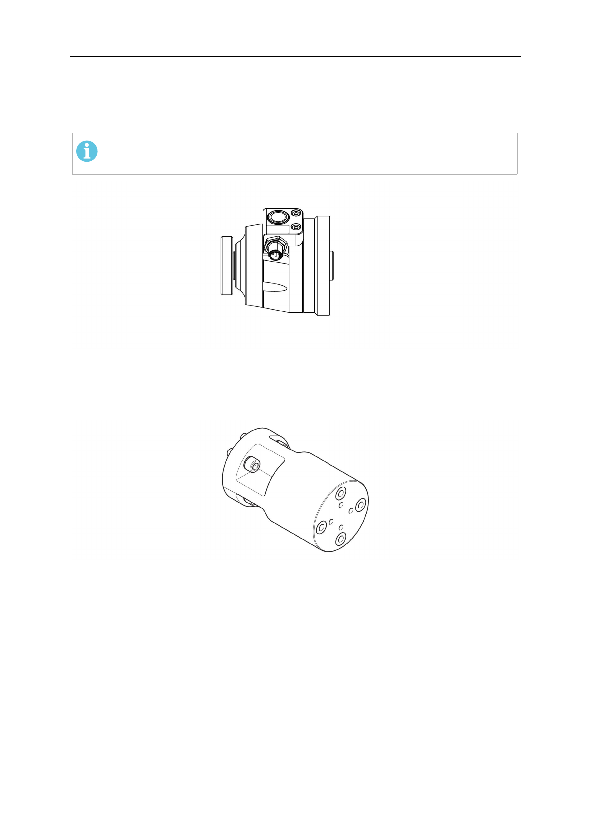
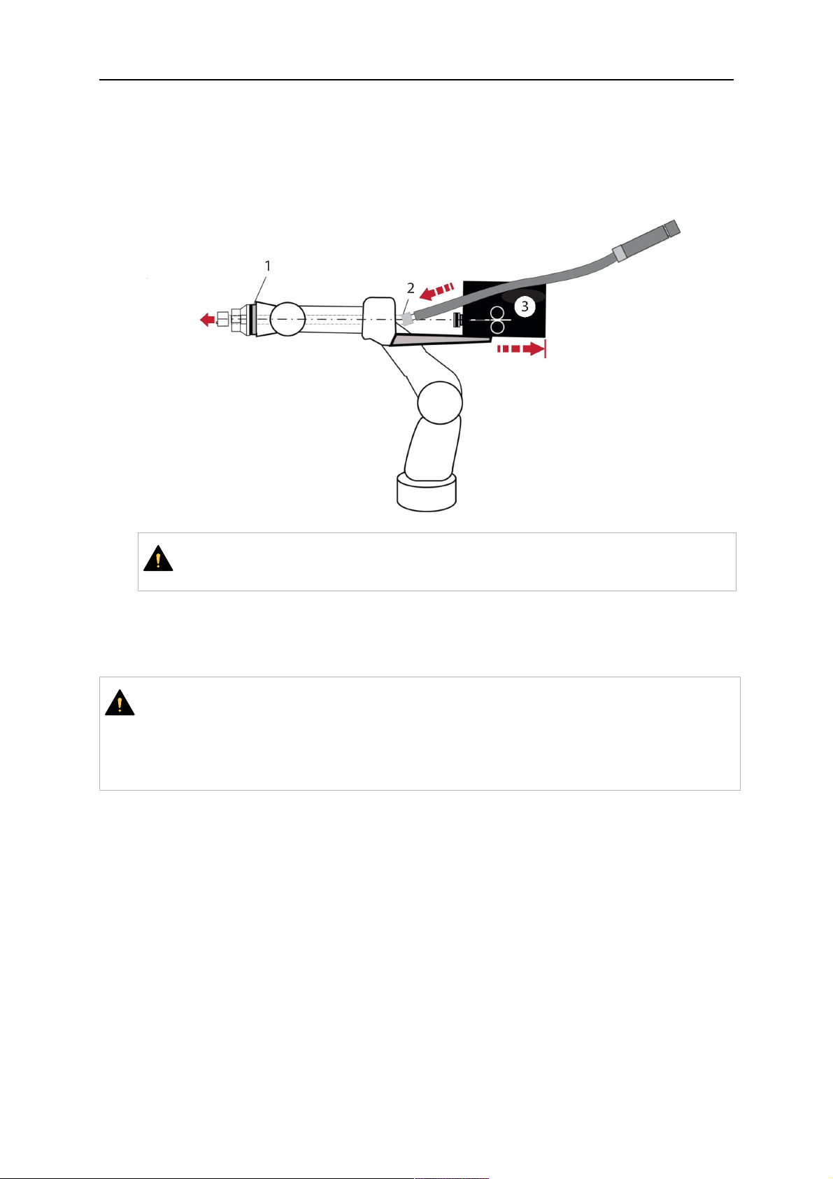
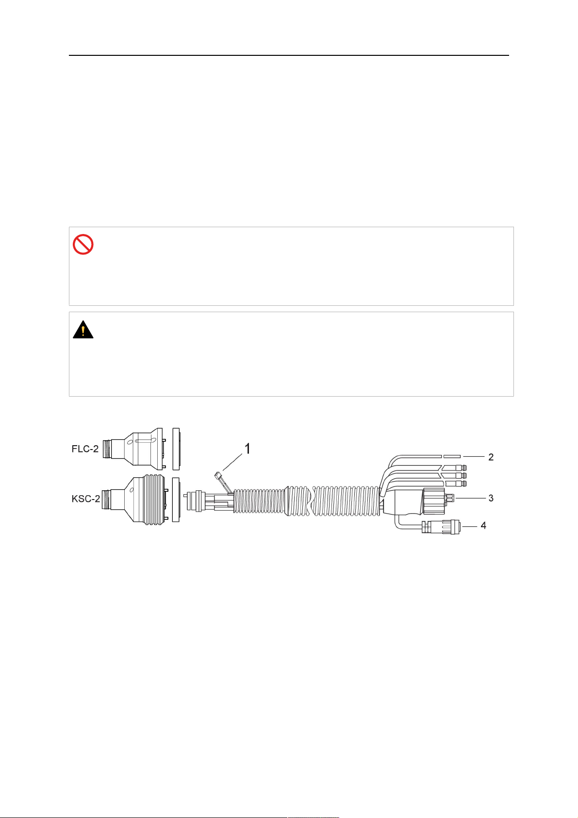
3.1 Pregled sistemov varilnih gorilnikov
Standardni sistem RT
Podroben opis si lahko ogledate v ustreznem
razdelku v poglavju TEHNIČNI PODATKI:
1. Vrat gorilnika
Glejte »Varilni gorilnik«.
2. Sklop kablov
Glejte »Sklopi kablov za standardni
sistem RT«.
3. Nosilec gorilnika
Glejte »Nosilci gorilnikov za
standardni sistem RT«.
4. Mehanizem varnostnega izklopa
RT KS-2
Glejte »Mehanizem varnostnega
izklopa RT KS-2«.
5. Vmesna prirobnica RT FL-2
Glejte »Vmesna prirobnica RT
FL-2«.
6. Prirobnica nastavka (če je
potrebna)
Glejte »Prirobnice nastavkov«.
0463 373 101
- 9 -
© ESAB AB 2018

3 UVOD
Sistem z votlim zapestjem
Podroben opis si lahko ogledate v ustreznem
razdelku v poglavju TEHNIČNI PODATKI:
1. Vrat gorilnika
Glejte »Varilni gorilnik«.
2. Nosilec gorilnika RT KSC-2
Glejte »Nosilec gorilnika RT KSC-2
z mehanizmom varnostnega
izklopa«.
3. Nosilec gorilnika RT FLC-2
Glejte »Togi nosilec gorilnika RT
FLC-2«.
4. Prirobnica nastavka
Glejte »Prirobnice nastavkov«.
5. Sklop kablov Helix ali Infiniturn
Glejte »Sklopi kablov za sisteme z
votlim zapestjem«.
0463 373 101
- 10 -
© ESAB AB 2018

4 TEHNIČNI PODATKI
4 TEHNIČNI PODATKI
4.1 Vrat varilnega gorilnika
Izberite model gorilnika glede na vrsto varjenja. Upoštevati morate potreben delovni cikel in
obremenitev, način hlajenja in premer žice. Če obstajajo povečane zahteve, na primer zaradi
predgretih obdelovancev ali visokega odboja toplote v kotih, morate upoštevati tudi te
zahteve ter izbrati varilni gorilnik z zadostno rezervno nazivno zmogljivostjo.
Varilni gorilniki RT so namenjeni uporabi z varilnimi transformatorji z oznako CE za varjenje
kovin v inertnem plinu (MIG), varjenje kovin v aktivnem plinu (MAG) in spajkanje MIG s
komercialnimi okroglimi žicami. Gorilnikov ne uporabljajte za druge postopke.
Za obločno varjenje jekla ali aluminija s pulznim tokom je treba uporabiti vodno hlajeni
gorilnik RT 82W.
Spodaj si oglejte modele gorilnikov, ki so na voljo.
Model gorilnika Način hlajenja Zaščitni plin Naznačena vrednost
RT42G Plinsko hlajenje CO
Plinsko hlajenje 300A/100%
Plinsko hlajenje Mešani 350A/60%
Plinsko hlajenje 250A/100%
RT42W Vodno hlajenje CO
Vodno hlajenje 420A/100%
Vodno hlajenje Mešani 350A/60%
Vodno hlajenje 350A/100%
RT52G Plinsko hlajenje CO
Plinsko hlajenje 300A/100%
Plinsko hlajenje Mešani 350A/60%
Plinsko hlajenje 250A/100%
RT52W Vodno hlajenje CO
Vodno hlajenje 470A/100%
Vodno hlajenje Mešani 400A/60%
Vodno hlajenje 400A/100%
RT62G Plinsko hlajenje CO
Plinsko hlajenje 340A/100%
2
2
2
2
2
420A/60%
420A/60%
420A/60%
470A/60%
500A/60%
Plinsko hlajenje Mešani 420A/60%
Plinsko hlajenje 290A/100%
RT62W Vodno hlajenje CO
Vodno hlajenje 530A/100%
Vodno hlajenje Mešani 450A/60%
Vodno hlajenje 450A/100%
RT72G Plinsko hlajenje CO
Plinsko hlajenje 320A/100%
Plinsko hlajenje Mešani 400A/60%
Plinsko hlajenje 270A/100%
0463 373 101
- 11 -
2
2
530A/60%
480A 60%
© ESAB AB 2018

4 TEHNIČNI PODATKI
Model gorilnika Način hlajenja Zaščitni plin Naznačena vrednost
RT72W Vodno hlajenje CO
2
480A/60%
Vodno hlajenje 430A/100%
Vodno hlajenje Mešani 480A/60%
Vodno hlajenje 430A/100%
RT82W Vodno hlajenje CO
2
600A/60%
Vodno hlajenje 600A/100%
Vodno hlajenje Mešani 550A/60%
Vodno hlajenje 550A/100%
Vrednosti za zmogljivost gorilnika in delovni cikel veljajo za 10-minutni cikel.
Tehnični podatki veljajo za standardiziran namen uporabe s standardnimi
obrabnimi/nadomestnimi deli. Zmogljivost gorilnika je manjša med obločnim varjenjem kovine
s pulznim tokom.
Temperaturna območja Shranjevanje: -15-50°C (5-122°F)
Uporaba: 5–40°C (41–104°F)
Plin za odpihovanje Najv. 10 barov, ločena plinska cev
Skupna teža (vrat gorilnika, mehanizem
Približno 5kg
varnostnega izklopa, nosilec gorilnika in
sklop 1 m dolgega kabla)
4.2 Nazivna napetost
Najv. dovoljena napetost/moč
Celovit sistem varilnih gorilnikov 141V (najvišja vrednost za varjenje)
Krmilno vezje varnostnega izklopa RT KS-2
Gumb RT KS-2
Krmilno vezje varnostnega izklopa RT KSC-2 48 V
Uporaba funkcije zaznavanja šobe s
standardnim sklopom kablov
Uporaba funkcije zaznavanja šobe s
sklopoma kablov Helix ali Infiniturn
Navedene zmogljivosti veljajo za standardizirane primere uporabe.
Za zmogljivosti sklopov kablov glejte razdelek »Sklopi kablov«.
4.2.1 Omejitve hladilnega krogotoka
Velja samo za vodno hlajene različice.
24V / 1A
48V / 0,1A
50V / 5A
(Dovoljena obremenitev najv. 1 minuta pri
nazivnem napajalnem toku)
50V / 5A
(Dovoljena obremenitev najv. 1 minuta pri
nazivnem napajalnem toku)
Najnižja hitrost pretoka vode: 1,0l/min
Najnižji tlak vode: 2,5bara (36,3psi)
Najvišji tlak vode: 3,5bara (50,8psi)
0463 373 101
- 12 -
© ESAB AB 2018

4 TEHNIČNI PODATKI
Temperatura v sesalnem
vodu:
Temperatura v povratnem
vodu:
Najv. 40°C (104°F)
Najv. 60°C (140°F)
Hladilna zmogljivost: Najm. 1000 W, odvisno od namena uporabe
PREVIDNO!
Temperature nad 60°C (140°F)v povratnem vodu lahko poškodujejo ali uničijo
sklop kablov.
4.3 Nosilec gorilnika
Od zasnove sistema varilnega gorilnika in izbire naprav za varnostni izklop je odvisno,
kakšen nosilec gorilnika potrebujete; glejte razdelek »Pregled sistemov varilnih gorilnikov«.
Komponente Približna teža:
Nosilec gorilnika (za standardni sistem) 0,43 kg
Mehanizem varnostnega izklopa RT KS-2 (za
standardni sistem)
Vmesna prirobnica RT FL-2 (za standardni
sistem)
0,85 kg
0,35 kg
Nosilec gorilnika RT KSC-2 (za sistem z
1,90 kg
votlim zapestjem)
Togi nosilec gorilnika RT FLC-2 (za sistem z
1,22 kg
votlim zapestjem)
Robotski varilni gorilnik 0,66 kg
4.3.1 Nosilec gorilnika za standardni sistem RT
Pri standardnih sistemih RT je nosilec gorilnika montiran na mehanizmu varnostnega izklopa
RT KS-2 (ali na vmesni prirobnici RT FL-2), pritrjen na sklop kablov in priključen vrat
gorilnika.
Izberite nosilec gorilnika v skladu z vrsto gorilnika in njegovo geometrijo. Uporabite lahko
različne vrste nosilcev. Nosilce gorilnikov, ki so na voljo za standardni sistem RT, si lahko
ogledate na seznamu nadomestnih delov.
Nosilec gorilnika za standardne robotske roke
0463 373 101
- 13 -
© ESAB AB 2018
4 TEHNIČNI PODATKI
4.3.1.1 Mehanizem varnostnega izklopa RT KS-2
Varnostni mehanizem RT KS-2 je vzmetena priprava, ki zaščiti robota in sistem gorilnika v
primeru trčenja.
OPOMBA!
Ne razstavljajte mehanizma RT KS-2.
4.3.1.2 Vmesna prirobnica RT FL-2
Namesto mehanizma RT KS-2 lahko uporabite togo vmesno prirobnico RT FL-2, če je robot
opremljen z elektronskim sistemom za zaznavanje trčenja.
4.3.2 Nosilci gorilnikov za sistem z votlim zapestjem
Pri sistemu z votlim zapestjem so vratovi varilnih gorilnikov Aristo RT povezani z nosilcem
gorilnika KSC-2 ali FLC-2.
Nosilec gorilnika RT KSC-2 omogoča elastični odklon gorilnika v primeru trčenja. Hkrati se
odpre električni stik, ki pošlje krmilnemu sistemu robota signal za zaustavitev. Po ponastavitvi
napake bosta začetna geometrija in središčna točka orodja (TCP) na gorilniku doseženi z
izjemno natančnostjo. Sistem deluje izključno mehansko in je vzmeten.
Nosilec gorilnika RT FLC-2 nima vgrajene funkcije varnostnega izklopa.
0463 373 101
- 14 -
© ESAB AB 2018

4 TEHNIČNI PODATKI
Za sisteme z votlim zapestjem priporočamo nosilec RT KSC-2 G/W (ali RT FLC-2 G/W). Ta
nosilec gorilnika lahko uporabljate tako s plinsko hlajenimi kot z vodno hlajenimi gorilniki
serije Aristo RT.
RTKSC-2 G/W RTFLC-2 G/W
Načelo delovanja mehanizma
Mehansko Ni relevantno (toga montaža)
varnostnega izklopa
Sila osne sprostitve (Fz) 650 N Ni relevantno (toga montaža)
Sprostitveni moment na
24 Nm Ni relevantno (toga montaža)
prečni osi (Mx)
Ponastavitev po sprostitvi Samodejno Ni relevantno (toga montaža)
Ponovljivost Bočno ± 0,1mm na točki TCP
Ni relevantno (toga montaža)
standardnega gorilnika Aristo
RT
Najv. odklon Pribl. ± 8° Ni relevantno (toga montaža)
Varnostno stikalo Običajno zaprto
Ni relevantno (toga montaža)
Najv. Električna obremenitev
48V / 1A
0463 373 101
- 15 -
© ESAB AB 2018

4 TEHNIČNI PODATKI
Električno krmilno vezje za
funkcijo zaznavanja šobe
Nazivna vrednost:
• Pri sklopih kablov Helix:
najv. 50V DC / 5A,
najv. 1 minuta
Po zaznavanju stika
hitro odklopite napetost
zaznavanja.
• Pri sklopih kablov
Infiniturn ima funkcija
zaznavanja šob
Nazivna vrednost:
• Pri sklopih kablov Helix:
najv. 50V DC / 5A,
najv. 1 minuta
• Pri sklopih kablov
Infiniturn: najv. 50V DC
/ 1 A, najv. 1 minuta
Po zaznavanju stika hitro
odklopite napetost
zaznavanja.
omejeno funkcionalnost.
Obrnite se na ESAB, če
želite podrobno
preiskavo mogočih
rešitev za svoj namen
uporabe.
Nazivna napetost Najvišja dovoljena napetost
za krmilno vezje varnostnega
izklopa: 48V.
4.3.2.1 Nosilec gorilnika RT KSC-2 z mehanizmom varnostnega izklopa
ArtikelOpis Funkcija
1 Nosilec vratu gorilnika Vmesnik gorilnika Aristo RT
2 Pokrov RT KSC-2 Sklop s kablom in vmesniki gorilnikov
3 Gumijasti plašč Zaščita za mehanizem varnostnega izklopa
0463 373 101
- 16 -
© ESAB AB 2018

4 TEHNIČNI PODATKI
ArtikelOpis Funkcija
4 Glavno ohišje RT KSC-2 Omogoča mehanski odklon v primeru trčenja
5 Prirobnica nastavka Izolacijski vmesnik za robotsko zapestje (ustrezati
mora določenemu robotu)
6 Kazalni zatič Za natančno poravnavo prirobnice nastavka
7 Konektor za krmilni kabel Električna povezava za signal v primeru trčenja in
funkcijo zaznavanja šobe
8 Mikrostikalo Tipalo za zaznavanje trčenja
4.3.2.2 Togi nosilec gorilnika RT FLC-2 G/W
ArtikelOpis Funkcija
1 Nosilec vratu gorilnika Vmesnik gorilnika Aristo RT
2 Pokrov RT FLC-2 Sklop s kablom in vmesniki gorilnikov
3 Glavno ohišje RT FLC-2 Omogoča mehanski odklon v primeru trčenja
4 Kazalni zatič Za natančno poravnavo prirobnice nastavka
5 Prirobnica nastavka Izolacijski vmesnik za robotsko zapestje (ustrezati
mora določenemu robotu)
6 Konektor za krmilni kabel
(3-polni)
0463 373 101
Električna povezava za funkcijo zaznavanja šobe
(če je relevantna)
- 17 -
© ESAB AB 2018

4 TEHNIČNI PODATKI
4.4 Prirobnice nastavkov
Izberite prirobnico nastavka, ki je potrebna za montažo na robotsko roko in je odvisna od
vrste robota. Na voljo so prirobnice nastavkov za vse ustrezne standardne sisteme in
sisteme z votlim zapestjem; oglejte si seznam nadomestnih delov.
4.5 Sklopi kablov
Sklop kablov vpliva na povezavo s podajalnikom žice. Različice, ki so na voljo, so večinoma
odvisne od zasnove sistema in hladilnega sredstva (plina ali vode); oglejte si seznam
nadomestnih delov.
Nazivne vrednosti veljajo za dolžine kabla od 1 do 5 m.
Standardni sklop
Infiniturn Helix
kablov
Moč (10-minutni cikel)
Plinsko hlajenje
(mešani plin)
Moč (10-minutni cikel)
Vodno hlajenje
Razpon kroženja Omejena zmožnost
Teža
Plinsko hlajenje
Teža
Vodno hlajenje
Najv. 500A (60 %
delovni cikel)
Najv. 350 A (100 %
delovni cikel)
Najv. 600 A (100 %
delovni cikel)
kroženja
1,2 m dolgo:
2,35 kg
1,2 m dolgo:
2,35 kg
Najv. 400 A (60 %
delovni cikel)
Najv. 320 A (100 %
delovni cikel)
Najv. 550 A (100 %
delovni cikel)
Neomejena zmožnost
kroženja
1,0 m dolgo:
2,0 kg
1,0 m dolgo:
2,0 kg
4.5.1 Sklopi kablov za standardni sistem RT
Najv. 400 A (60 %
delovni cikel)
Najv. 320 A (100 %
delovni cikel)
Najv. 550 A (100 %
delovni cikel)
± 270° iz nevtralnega
položaja
1,0 m dolgo:
2,0 kg
1,0 m dolgo:
2,0 kg
0463 373 101
- 18 -
© ESAB AB 2018

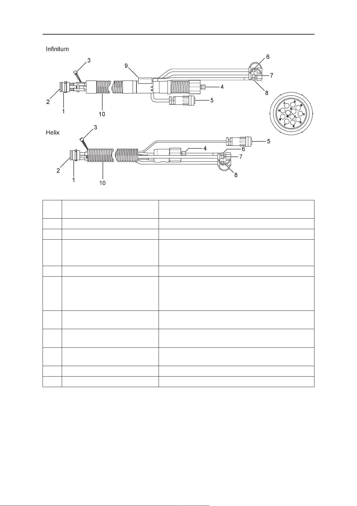
4 TEHNIČNI PODATKI
Nožice konektorja Burndy
A. Plinska šoba z
zaznavanjem dotika
C. Tipalo za zaznavanje
trčenja
F. 0V
G. + Napetost motorja
H. - Napetost motorja
D. Tipalo za zaznavanje
trčenja
E. Koračno pomikanje
ArtikelOpis Funkcija
1 Prirobnica nosilca vratu Vmesnik gorilnika
2 Zaščitni pokrov Ščiti sklop kablov pred poškodbami
3 Konektor Burndy, 12-polni Električna povezava med funkcijo varnostnega
izklopa in podajalnikom žice
4 Krmilni kabel Za KS-2 (varnostni izklop in gumb)
5 EURO-priključek Povezava za podajalnik žice
6 Cev za izpihovanje (črn
pokrovček)
7 Dovodna odprtina za vodo
Za čiščenje gorilnika s stisnjenim zrakom po ciklu
čiščenja
Dovodna odprtina za vodo za hlajenje gorilnika
(moder pokrovček)
8 Povratni vod za vodo (rdeč
Povratni vod za vodo, ki jo segreje gorilnik
1)
pokrovček)
1)
9 Vtič krmilnega kabla za
mehanizem varnostnega
izklopa
1)
Samo sistemi vodno hlajenih gorilnikov
Električna povezava z mehanizmom RT KS-2 za
signal varnostnega izklopa in funkcijo zaznavanja
šobe
4.5.2 Sklopi kablov za sisteme z votlim zapestjem
Sklop kablov Infiniturn omogoča neomejeno vrtenje gorilnika v obe smeri. Hkrati prihaja do
prenosa hladilne tekočine, zaščitnega plina, zraka za izpihovanje, energije za varjenje in
signala mehanizma varnostnega izklopa.
Sklop kablov Helix je zasnovan za razpon vrtenja ±270° iz nevtralnega položaja. Lahko se
uporablja za varilna opravila, ki ne zahtevajo neomejenega vrtenja.
Sklopi kablov Infiniturn so na voljo v plinsko hlajenih in vodno hlajenih različicah. Sklopi
kablov Helix se lahko univerzalno uporabljajo s plinskim ali vodnim hlajenjem.
OPOMBA!
Ne priključite sklopa kablov Helix s plinsko hlajenim vratom gorilnika na vodno
hlajeni sistem.
0463 373 101
- 19 -
© ESAB AB 2018
4 TEHNIČNI PODATKI
ArtikelOpis Funkcija
1 Prirobnica Vmesnik nosilca gorilnika RT KSC-2 / RT FLC-2
2 Kazalni zatič Zagotavlja pravilno usmerjenost priključka
3 Vtič krmilnega kabla Električna povezava z mehanizmom RT KSC-2 za
signal varnostnega izklopa in funkcijo zaznavanja
šobe (če je relevantna)
4 EURO-priključek Povezava za podajalnik žice
5 Krmilni kabel Električna povezava za signal varnostnega izklopa
(iz mehanizma RT KSC-2) in funkcijo zaznavanja
šobe (zaznavanje šobe je standardno pri sklopu
kablov Helix, ne pa pri sklopu kablov Infiniturn)
6 Povratni vod za vodo (rdeč
Povratni vod za vodo, ki jo segreje gorilnik
pokrovček)
7 Dovodna odprtina za vodo
Dovodna odprtina za vodo za hlajenje gorilnika
(moder pokrovček)
8 Cev za izpihovanje (črn
pokrovček)
Za čiščenje gorilnika s stisnjenim zrakom po
varjenju
9 Priključek za sredstva Neomejeno vrtljiv priključek za prenos sredstev
10 Zaščitni pokrov Ščiti sklop kablov pred poškodbami
0463 373 101
- 20 -
© ESAB AB 2018

5 INSTALLATION
5 INSTALLATION
POZOR!
For your own safety, make sure that the robot is either in standby or power-less
state before doing maintenance work in the moving radius of the robot.
Follow the assembly instructions exactly. Pay attention during assembly that the cables are
not damaged. Damaged cables can lead to a short circuit, which may damage the electronics
of the robot or the welding torch.
Use only original ESAB components that have been specially developed for this purpose.
Only then the correct functioning of the whole welding torch system can be guaranteed.
5.1 RTKS-2 standard arm installation
5.1.1 RTKS-2 safety-off mechanism
1. Dismount the insulation flange (10) from the RTKS-2 (11) by removing the screws
(12).
2. Position the insulation flange (10) with the index pin on the robot arm and fix it with the
screws (20) included.
The insulation flange (10) is directly compatible with robots with tool flange according
to DIN ISO 9409-1-A40 (diameter 40mm, 4×M6). If the insulation flange (10) does
not fit, use an adapter flange (21).
OPOMBA!
Ensure that the index pin is located correctly. The maximum torque of 1.2Nm
(10.5in.lb) must be observed for the fastening of the adapter flange screws.
Prevent self-loosening of the screws by using suitable thread locking
measures.
3. Mount the RTKS-2 the back on the insulation flange (10).
0463 373 101
- 21 -
© ESAB AB 2018

5 INSTALLATION
4. Position the mount on the RTKS-2 and carefully insert the cylindrical pins (14) into the
holes provided. Take the position of the torch into account. Two mounting positions
may be potentially possible.
5. Screw the mount evenly using the enclosed cylinder screws with hexagon socket (12).
OPOMBA!
The maximum tightening torque for the cylinder screw (5) is 6Nm (53in.lb)
and the property class category is 8.8.
12 - Cylinder screw with hexagon socket
M6DIN912 (length of the screw depending
on the torch mount)
14 - Cylindrical pins Ø4×20
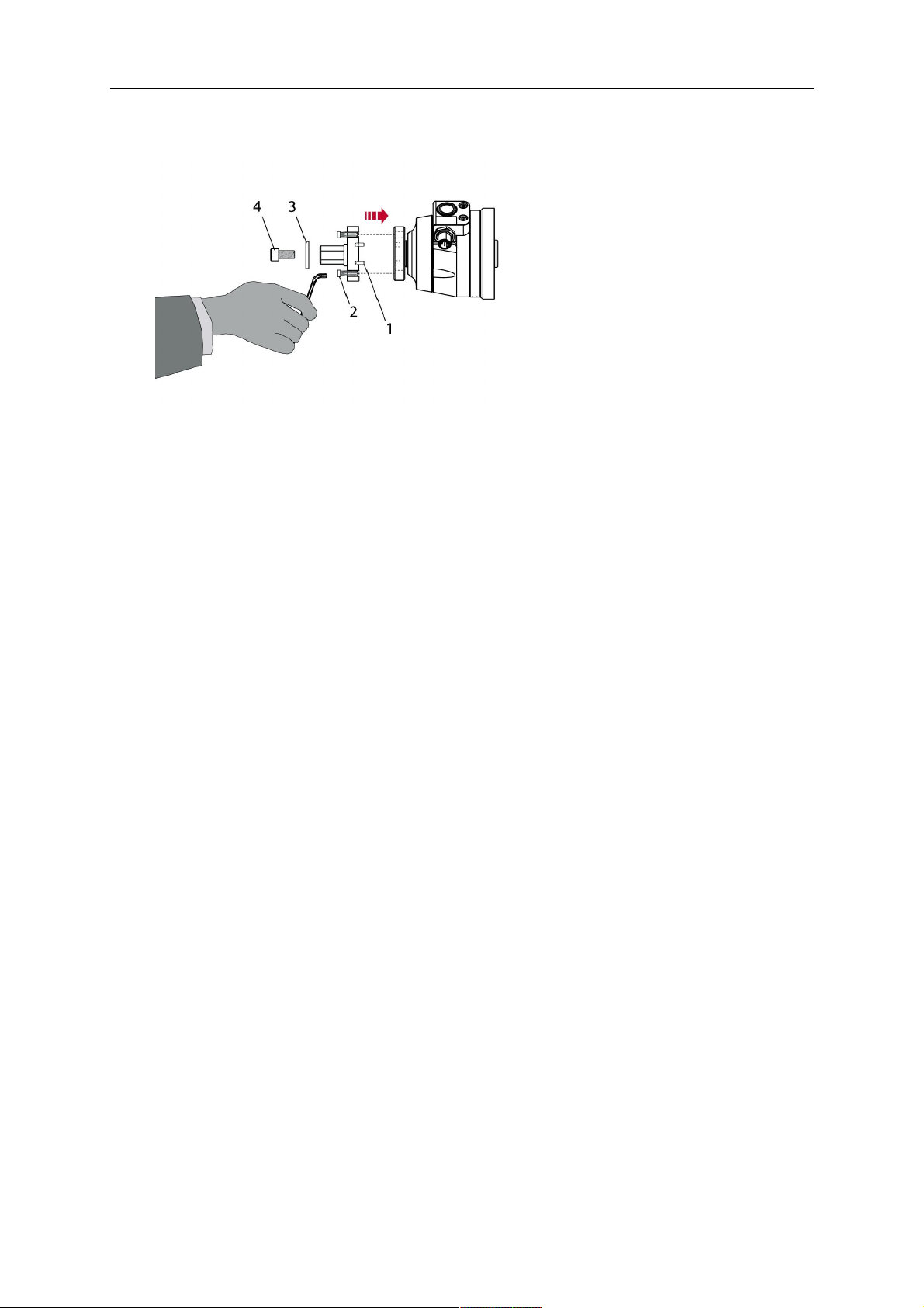
5.1.1.1 Torch installation with adjustable mount
Torch mounts with a central clamping assembly can only be fastened on the journal of the
mounting flange. For this, the mounting flange must be fastened first.
1. If applicable, carefully press the cylindrical pins (1) into the corresponding holes in the
mounting flange. The pins should protrude by approximately 5 mm (0.2 in.).
2. Position the mount on the safety-off mechanism RTKS-2 and carefully insert the
cylindrical pins (1) into the holes provided. In doing so, take the later position of the
torch into account. Two mounting positions may be potentially possible.
3. Then screw down the mounting flange evenly using the enclosed cylinder screws with
hexagon socket (2).
OPOMBA!
The maximum tightening torque for the cylinder screw (2) is 7.1 Nm (62.8
in.lb) and the property class category is 8.8.
0463 373 101
- 22 -
© ESAB AB 2018
5 INSTALLATION
4. Unscrew the axial cylinder screw with hexagon socket (4) out of the mounting flange
together with the washer (3).
1 - Cylindrical pins Ø4×14 3 - Washer Ø9 mm
2 - Cylinder screw with hexagon socket
M6×16
4 - Axial cylinder screw with hexagon
socket M8×16
5. Place the torch mount (5) onto the journal (6) of the mounting flange, paying attention
while doing so to the exact alignment of the feather key (7) and the corresponding
groove (7a).
6. Insert the clamping mandrel (8) into the lateral hole (see illustration) and position it so
that the mating surfaces (9a) of the clamping mandrel rest on the mating surface (9) of
the journal.
0463 373 101
- 23 -
© ESAB AB 2018

5 INSTALLATION
7. Fix the clamping mandrel from the opposite side using the M6 cylinder screw with
hexagon socket (10) and the Ø22 mm washer (11).
8. Screw the axial cylinder screw (4) with the Ø9 mm washer (3) into the mounting flange
and tighten firmly.
3 - Washer Ø9 mm 8 - Clamping mandrel
4 - Axial cylinder screw with hexagon
9 - Mating surface of mounting flange
socket M8×16
5 - Torch mount 9a - Mating surfaces of clamping mandrel
6 - Mounting flange journal 10 - Cylinder screw with hexagon socket
M6×30
7 Feather key 11 - Washer Ø22×6.4 mm
7a - Groove for feather key
5.1.2 Standard arm cable assembly for KS-2 and FL-2
The cable assembly must be aligned to the intended use in length and design. The type of
cooling for the torch and the cable assembly must be the same (either gas or water cooled
respectively). In order to prevent damage to the torch system and other components, it is
imperative to observe the following instructions.
0463 373 101
- 24 -
© ESAB AB 2018

5 INSTALLATION
PREVIDNO!
• Coordinate the length and design of the cable assembly to suit the range of
action of the robot.
• Do not bend, compress or overstretch the cable assembly.
• Fix the cable assembly such that is can be moved freely and cannot become
entangled.
• Any additional holding devices possibly installed, for example a balancer,
must not crush or bend the cable assembly.
• Extreme turning movements must be avoided in which the cable assembly
may become twisted.
• Chafing on the robot or other objects must be excluded.
1. Unscrew the cylinder screws (1) and lift off the top section (2) of the torch mount.
2. Insert the feather key (4) into the recess of the neck support flange (3) from below.
3. Align the neck support flange (3) including the feather key (4) to the groove (5) of the
torch mount and push into the groove right up to the stop of the flange.
4. Hold the cable assembly in this position and simultaneously place the top section (2)
back onto the torch mount. First screw both cylinder screws (1) loosely in to about the
same length, then tighten alternately. The top section (2) of the mount should have an
even gap to the bottom section.
The front part of the cable assembly is directly clamped into the torch mount (see
illustration below).
1 - Cylinder screws 4 - Feather key
2 - Torch mount top section 5 - Groove for feather key
3 - Neck support flange
5.1.3 RTKS-2 wire feeder connection
In order to be able to create the connection, the cable assembly must be mounted as
described in the "Installing the cable assembly" section and equipped following "Installing the
wire guide" section. Only then can the central and media connection take place. Proceed as
described below:
0463 373 101
- 25 -
© ESAB AB 2018

5 INSTALLATION
1. Connect the central connector of the cable assembly (2) to the wire feeder cabinet
socket. Tighten the central connector sleeve nut fingertight. Do not use tools.
1 - Burndy Connector 4 - Return of heated water (red cap)
2 - EURO central connector 5 - Return of heated water (red cap)
3 - Air blow-out 6 - Main Wire feeder
2. For water cooled systems. Connect the water hoses to the cooling circuit. The end of
the hose marked blue (4) is connected to the water outlet, and the end marked red (5)
is connected to the water return.
3. Connect the blow-out line (3) to the corresponding connection of the feeder.
4. Connect the Burndy Connector to the wire feeder. (1) to the feeder. See section
"Electrical connections".
OPOMBA!
All hoses and the control line must be installed so they can not bend or get
damaged!
5.1.4 RTKS-2 electrical connections
5.1.4.1 RTKS-2 safety-off mechanism connection
The switch for the safety-off functionality RTKS-2 is connected through the control cable,
see (3) in the illustration below. This connects to the RTKS-2 unit via the 4-pole plug (4) that
contains circuits for the push-button (6) and the safety-off signal (7).
If a collision is detected, the control circuit for the safety-off signal (7), which is normally
closed, will be interrupted.
Rating of the control circuit: max. 48 V / 1 A
0463 373 101
- 26 -
© ESAB AB 2018

5 INSTALLATION
2 - Burndy connector 5 - RTKS-2 connector for control cable plug
4 - Control cable plug
Nožice konektorja Burndy
A. Plinska šoba z
zaznavanjem dotika
C. Tipalo za zaznavanje
trčenja
F. 0V
G. + Napetost motorja
H. - Napetost motorja
D. Tipalo za zaznavanje
trčenja
E. Koračno pomikanje
If the robot control provides a control circuit for nozzle sense functionality, the connection is
accomplished with a 1-wire connection.
Rating of the control circuit: max 50 V / 5 A.
NEVARNOST!
If the nozzle sense function is not being used, the open end of the control cable on
the power source connection side must be properly isolated in order to avoid short
circuits. During certain problems on the torch head, the full welding potential may be
present on this cable.
PREVIDNO!
After detection of contact (gas nozzle on work piece), quickly reduce or cut off the
maximum current in the nozzle sense circuit in order to avoid overloading of the
system.
Allowed load max. 1 minute at the rated nominal current.
5.1.5 RTKS-2 Torch installation
Continue according to section "Torch installation".
0463 373 101
- 27 -
© ESAB AB 2018

5 INSTALLATION
5.2 RTFL-2 standard arm installation
5.2.1 RTFL-2 rigid mount
1. Position the RT FL-2 (2) with the index pin on the robot arm and fix it with the hexagon
socket screw included.
The FL-2 is directly compatible with robots with tool flange according to DIN ISO
9409-1-A40 (diameter 40mm, 4×M6). If the rigid mount does not fit, use an adapter
flange (3).
OPOMBA!
Ensure that the index pin is located correctly. The maximum torque of 1.2Nm
(10.5in.lb) must be observed for the fastening of the adapter flange screws.
Prevent self-loosening of the screws by using suitable thread locking
measures.
2. Install torch mount (1). Only torch mounts having a hole pattern equivalent with the
mounting surface may be attached. If necessary, carefully press the cylindrical pins (4)
into the corresponding holes in the bracket. The pins should protrude by
approximately 5mm (0.2in.). Position the torch mount on the RTFL-2 (2) and
carefully insert the cylindrical pins (4) into the holes provided. Take the position of the
torch into account. Two mounting positions may be potentially possible.
3. Screw the mount evenly using the enclosed cylinder screws with hexagon socket (5).
OPOMBA!
The maximum tightening torque for the cylinder screw (5) is 6Nm (53in.lb)
and the property class category is 8.8.
0463 373 101
- 28 -
© ESAB AB 2018

5 INSTALLATION
4 - Cylindrical pins Ø4×20
5 - Cylinder screw with hexagon socket M6
DIN 912 (length of the screw depending on
the torch mount)
Side view
Torch installation with adjustable mount
Torch mounts with a central clamping assembly can only be fastened on the journal of the
mounting flange. For this, the mounting flange must be fastened first.
1. If applicable, carefully press the cylindrical pins (1) into the corresponding holes in the
mounting flange. Avoid the formation of burrs. The pins should protrude by
approximately 5 mm (0.2 in.).
2. Position the mount on the RTFL-2 and carefully insert the cylindrical pins (1) into the
holes provided. In doing so, take the later position of the torch into account. Two
mounting positions may be potentially possible.
3. Then screw down the mounting flange evenly using the enclosed cylinder screws with
hexagon socket (2).
OPOMBA!
The maximum tightening torque for the cylinder screw (2) is 7.1 Nm (62.8
in.lb) and the property class category is 8.8.
4. Unscrew the axial cylinder screw with hexagon socket (4) out of the mounting flange
together with the washer (3).
1 - Cylindrical pins Ø4×14 3 - Washer Ø9 mm
2 - Cylinder screw with hexagon socket
M6×16
4 - Axial cylinder screw with hexagon
socket M8×16
5. Place the torch mount (5) onto the journal (6) of the mounting flange, paying attention
while doing so to the exact alignment of the feather key (7) and the corresponding
groove (7a).
0463 373 101
- 29 -
© ESAB AB 2018

5 INSTALLATION
6. Insert the clamping mandrel (8) into the lateral hole (see illustration) and position it so
that the mating surfaces (9a) of the clamping mandrel rest on the mating surface (9) of
the journal.
7. Fix the clamping mandrel from the opposite side using the M6 cylinder screw with
hexagon socket (10) and the Ø22 mm washer (11).
8. Screw the axial cylinder screw (4) with the Ø9 mm washer (3) into the mounting flange
and tighten firmly.
3 - Washer Ø9 mm 8 - Clamping mandrel
4 - Axial cylinder screw with hexagon
9 - Mating surface of mounting flange
socket M8×16
5 - Torch mount 9a - Mating surfaces of clamping mandrel
6 - Mounting flange journal 10 - Cylinder screw with hexagon socket
M6×30
7 - Feather key 11 - Washer Ø22×6.4 mm
7a - Groove for feather key
5.2.2 RTFL-2 torch installation
Continue according to section "Torch installation".
5.3 RTKSC-2 hollow wrist system installation
5.3.1 RTKSC-2 mount with safety off mechanism
PREVIDNO!
For hollow wrist systems make sure that the clear space around the robot is at least
Ø45 mm (1.8 in.) around the wrist and 50 mm (2.0 in.) near the wire feeder.
0463 373 101
- 30 -
© ESAB AB 2018

5 INSTALLATION
1. Remove the three screws (2) from the front cover (3) of the torch mount and carefully
pull the cover off the RTKSC-2 main body (5). Take care not to damage the micro
switches installed inside the assembly.
1 - Hexagon wrench 4 mm 4 - Rubber boot
2 - 3× M5×12 screws 5 - RT KSC-2 main body
3 - RT KSC-2 front cover
1. Pull off the rubber boot (4) from the RTKSC-2 main body (5) to the front.
2. Now position the RTKSC-2 main body (5) on the adapter flange (7) so that the index
pin is correctly seated. Attach with the screws (6) enclosed.
3. Reinstall the rubber boot (4) on the RTKSC-2 main body (5) and make sure it is
correctly located in the grooves on the front and back flange.
4. Istall the adapter flange (7) on the robot.
Fastening torque max. 2.2 Nm (19.5 in.lb).
1 - Hexagon wrench 4 mm 3 - 3× M5×12 hexagon socket screws
2 - Rubber boot 4 - Adapter flange
5.3.2 Mounting the cable assembly
OPOMBA!
In order to adjust the wire feeder position to the cable assembly length, it must be
mounted on an adjustable support with a possible movement of ±2-3cm (±1in.) to
the back and to the front. The length of the cable assembly must be determined
from the centred mounting position of the wire feeder.
1. Move the robot arm into a completely straight position, see illustration below. Make
sure that (1) axis 6 (rotation around the torch axis) is in 0° position.
2. Move the feeder (3) completely to the back in order to create space for inserting the
cable assembly. If it is not possible to move the feeder sufficiently, it should be
removed from the robot.
0463 373 101
- 31 -
© ESAB AB 2018
5 INSTALLATION
3. Insert the cable assembly with the coupling (2) first into the robot arm and feed it
through the robot wrist.
4. The feeder should only be installed again after the correct mounting position with
respect to the cable length has been determined. (See section "Installing the cable
assembly").
PREVIDNO!
Axis 6 must be in 0° position.
5.3.2.1 RTKSC-2 feeder cabinet connections
When installed for the first time, the position of the wire feeder cabinet must be adjusted to
the length of the cable assembly. First, the robot arm must be fully extended (straight).
PREVIDNO!
As long as the correct position of the feeder corresponding to the length of the cable
assembly has not been determined, be careful when moving the robot arm and
avoid overstretching the cable. It is helpful to loosen the positioning screws of the
feeder before moving the robot arm to allow the feeder to follow the cable assembly.
0463 373 101
- 32 -
© ESAB AB 2018

5 INSTALLATION
1. Loosen the sliding mechanism of the wire feeder and connect the cable assembly.
2. Now adjust the position of the wire feeder to suit the length of the Infiniturn or Helix
cable, as indicated with "A" in the illustration below.
PREVIDNO!
When adjusting the position of the feeder cabinet, make sure that the cable
assembly is not under stress when the robot arm is in stretched-out position.
It is normal for the cable assembly to sag slightly, it should never be taut.
3. Before securing the wire feeder in its permanent position, ensure that the Euro
connectors are tightly connected. Then turn the torch mount down and up again
(rotating on the axis 5), in order not to tighten the cable assembly too much against
the feeder (see illustration above). Once this is done, tighten the feeder in that
position.
4. For water cooled systems, connect the water lines to the cooling circuit. See section
"Cable assemblies for hollow wrist systems" in the TECHNICAL DATA chapter for
indications.
The hose with the blue rubber cap is for cooling water to the torch, the hose with the
red rubber cap returns the heated water. Make sure the hoses will not kink or get
otherwise blocked.
OPOMBA!
A Helix cable assembly used for a gas cooled system must not be connected
to a cooling circuit. As the water connections are not needed, they may be cut
off.
5. Connect the blow-out hose (black rubber cap) to the corresponding outlet of the wire
feeder.
OPOMBA!
If the blow-out function is not used, the blow-out hose must be sealed with the
rubber cap enclosed. With Infiniturn systems, the blow-out air must be
supplied to the corresponding connection hose, if it is not permitted to connect
blow-out air to the shield gas connection!
6. Install the necessary plug on the control cable and connect it to the safety off circuit
interface of the wire feeder (see section "Electrical connections").
0463 373 101
- 33 -
© ESAB AB 2018
5 INSTALLATION
5.3.3 RTKSC-2 cable assembly
The cable assembly must be aligned to the intended use in length and design. The type of
cooling for the torch and the cable assembly must be the same (either gas or water cooled
respectively). In order to prevent damage to the torch system and other components, it is
imperative to observe the following instructions.
PREVIDNO!
• Coordinate the length and design of the cable assembly to suit the range of
action of the robot.
• Do not bend, compress or overstretch the cable assembly.
• Fix the cable assembly such that is can be moved freely and cannot become
entangled.
• Any additional holding devices possibly installed, for example a balancer,
must not crush or bend the cable assembly.
• Extreme turning movements must be avoided in which the cable assembly
may become twisted.
• Chafing on the robot or other objects must be excluded.
5.3.3.1 RTKSC-2 cable assembly installation
OPOMBA!
For some robots, it may be possible to deviate from this order, and first connect the
cable assembly to the RTKSC-2, then thread the cable from the front through the
robot arm. If in doubt, follow the suggested order.
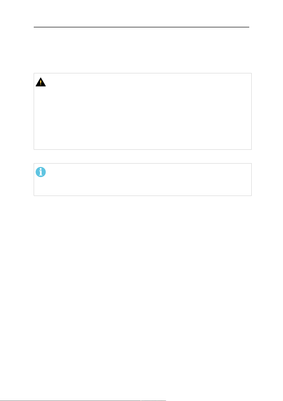
1. Loosen the three screws (7) with the associated washers and remove them from the
RTKSC-2 cover (1). See illustration below.
2. Install the supplied O-rings (4) into the grooves in the cover (1).
3. Pull the cable assembly approximately 15 cm (6 in.) from the main body (3).
0463 373 101
- 34 -
© ESAB AB 2018

5 INSTALLATION
4. Insert the coupling (2) into the socket of the cover (1) as shown. Align the index pin (6)
with the index hole (5) in the main body and insert completely.
OPOMBA!
Make sure that the position of the O-rings are not shifted by the index pin
during the assembly.
1 - RTKSC-2 cover 5 - Index hole
2 - Coupling 6 - Index pin
3 - RTKSC-2 main body 7 - 3× M5×35 screws
4 - 3× O-ring for water cooled systems 11 - Control cable connector
5. Insert the three screws (7) with the associated washers (8) and tighten gently with the
enclosed hexagonal wrench, see below illustration.
Fastening torque approximately 2 Nm (18 in.lb).
0463 373 101
- 35 -
© ESAB AB 2018

5 INSTALLATION
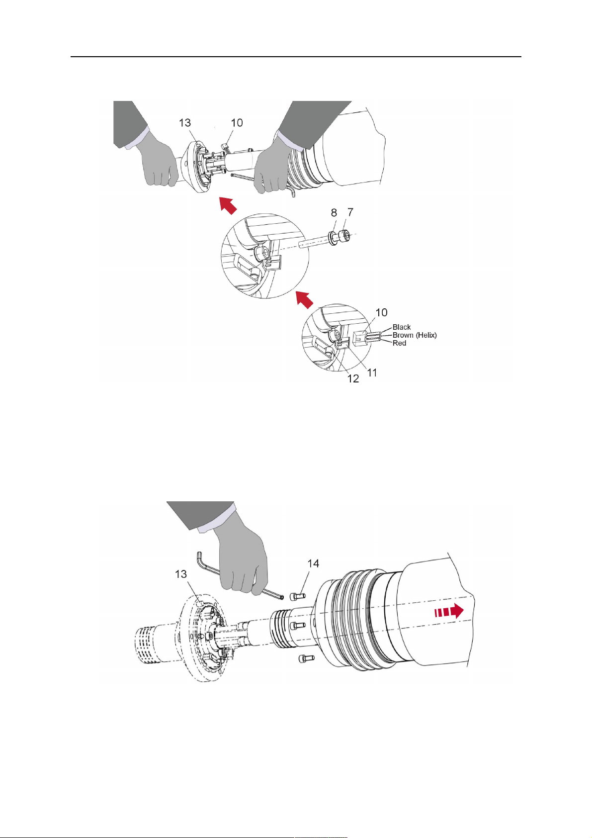
6. If present, insert the control cable plug (10) into the connector (11) and make sure it is
firmly seated.
7 - 3× M5×35 screw 11 - Control cable connector
8 - Washer 12 - 2× Micro switch
10 - Control cable plug 13 - Index pin
7. Gently push back the cable assembly into the robot arm and carefully seat the
RTKSC-2 cover (1) in place. Observe the index pin (13) to be in the correct position.
Make sure the two micro switches (12) are not damaged if present.
8. Insert the three M5 screws (14) and tighten without excessive force.
13. Index pin
14. 3× M5×12 screws
0463 373 101
- 36 -
© ESAB AB 2018

5 INSTALLATION
5.3.3.2 RTKSC-2 electrical connections
OPOMBA!
After connecting the control cable, secure the cable in order to protect it from getting
caught while the robot is moving.
Usually, the control cable will be directly connected to the wire feeder. See the
manufacturer's documentation for details. The link to the robot control is then
implemented via the power source controller.
RTKSC-2 safety-off mechanism connection
The switch for the safety-off functionality RTKSC-2 is connected through the control cable,
see (3) in the illustration below. This connects to the RTKSC-2 unit via the control cable plug
(1).
The safety-off signal requires a 2-wire connection (black/black) to the safety-off circuit in the
robot control (5).
If a collision is detected, the control circuit (normally closed) will be interrupted (4).
Rating of the control circuit: max. 48 V / 1 A.
1 - Control cable plug 3 - Burndy connector VVV
2 - EURO central connector
Nožice konektorja Burndy
A. Plinska šoba z
zaznavanjem dotika
C. Tipalo za zaznavanje
trčenja
F. 0V
G. + Napetost motorja
H. - Napetost motorja
D. Tipalo za zaznavanje
trčenja
E. Koračno pomikanje
RTKSC-2 nozzle sense function connection
If the robot control provides a control circuit for nozzle sense functionality.
The connection is accomplished with a 2-wire connection (black/black) to the nozzle sense
circuit in the robot control (5), see illustration below.
0463 373 101
- 37 -
© ESAB AB 2018

5 INSTALLATION
Usually, the control cable will be directly connected to the wire feeder. See the
manufacturer's documentation for details. The link to the robot control is then implemented
via the power source robot interface.
Rating of the control circuit: max. 50 V / 5 A.
NEVARNOST!
If the nozzle sense function is not being used, the open end of the control cable on
the power source connection side must be properly isolated in order to avoid short
circuits. During certain problems on the torch head, the full welding potential may be
present on this cable.
PREVIDNO!
After detection of contact (gas nozzle on work piece), quickly reduce or cut off the
maximum current in the nozzle sense circuit in order to avoid overloading of the
system.
Allowed load max. 1 minute at the rated nominal current.
1 - Control cable plug 3 - Control cable
2 - EURO central connector
5.3.4 RTKSC-2 torch installation
Continue according to section "Torch installation".
0463 373 101
- 38 -
© ESAB AB 2018

5 INSTALLATION
5.4 RTFLC-2 installation
5.4.1 RTFLC-2 mount
1. Remove the three M5 screws (2) from the front cover (3) of the RT FLC-2 torch mount
and carefully pull the cover off the main body (4).
1 - Hexagon wrench 4 mm 3 - RT FLC-2 front cover
2 - 3× M5×12 screws 4 - RT FLC-2 main body
2. Now position the RT FLC-2 main body (4) on the adapter flange (6) so that the index
pin is correctly seated. Attach with the screws (5) enclosed
Fastening torque max. 2.2 Nm (19.5 in.lb).
1 - Hexagon wrench 4 mm 5 - 3× M5×12 hexagon socket screws
4 - RT FLC-2 main body 6 - Adapter flange
5.4.2 RTFLC-2 wire feeder connection
5.4.2.1 Feeding through the robot arm
OPOMBA!
In order to adjust the wire feeder position to the cable assembly length, it must be
mounted on an adjustable support with a possible movement of ± 2-3 cm (± 1 in.) to
the back and to the front. The length of the cable assembly must be determined
from the centred mounting position of the wire feeder.
0463 373 101
- 39 -
© ESAB AB 2018

5 INSTALLATION
1. Move the robot arm into a completely straight position, see illustration below. Make
sure that (1) axis 6 (rotation around the torch axis) is in 0° position.
2. Move the feeder (3) completely to the back in order to create space for inserting the
cable assembly. If it is not possible to move the feeder sufficiently, it should be
removed from the robot.
3. Insert the cable assembly with the coupling (2) first into the robot arm and feed it
through the robot wrist.
4. The feeder should only be installed again after the correct mounting position with
respect to the cable length has been determined. (See section "Installing the cable
assembly").
PREVIDNO!
Important! Axis 6 must be in 0° position.
5.4.2.2 RTFLC-2 feeder cabinet connections
When installed for the first time, the position of the wire feeder cabinet must be adjusted to
the length of the cable assembly. First, the robot arm must be fully extended (straight).
PREVIDNO!
As long as the correct position of the feeder corresponding to the length of the cable
assembly has not been determined, be careful when moving the robot arm and
avoid overstretching the cable. It is helpful to loosen the positioning screws of the
feeder before moving the robot arm to allow the feeder to follow the cable assembly.
0463 373 101
- 40 -
© ESAB AB 2018

5 INSTALLATION
1. Loosen the sliding mechanism of the wire feeder and connect the cable assembly.
Refer to the instruction of the feeder manufacturer.
2. Now adjust the position of the wire feeder to suit the length of the Infiniturn or Helix
cable, as indicated with "A" in the illustration below.
PREVIDNO!
When adjusting the position of the feeder cabinet, make sure that the cable
assembly is not under stress when the robot arm is in stretched-out position.
It is normal for the cable assembly to sag slightly, it should never be taut.
3. Before securing the wire feeder in its permanent position, ensure that the Euro
connections are tightly connected. Then turn the torch mount down and up again
(rotating on the axis 5), in order not to tighten the cable assembly too much against
the feeder (see illustration above). Once this is done, tighten the feeder in that
position.
4. For water cooled systems, connect the water lines to the cooling circuit. See section
"Cable assemblies for hollow wrist systems" in the TECHNICAL DATA chapter for
indications.
The hose with the blue rubber cap is for cooling water to the torch, the hose with the
red rubber cap returns the heated water. Make sure the hoses will not kink or get
otherwise blocked.
OPOMBA!
A Helix cable assembly used for a gas cooled system must not be connected
to a cooling circuit. As the water connections are not needed, they may be cut
off.
5. Connect the blow-out hose (black rubber cap) to the corresponding outlet of the wire
feeder.
OPOMBA!
If the blow-out function is not used, the blow-out hose must be sealed with the
rubber cap enclosed. With Infiniturn systems, the blow-out air must be
supplied to the corresponding connection hose, if it is not permitted to connect
blow-out air to the shield gas connection!
0463 373 101
- 41 -
© ESAB AB 2018

5 INSTALLATION
6. Install the necessary plug on the control cable and connect it to the safety off circuit
interface of the wire feeder (see section "Electrical connections").
5.4.3 RTFLC-2 cable assembly
The cable assembly must be aligned to the intended use in length and design. The type of
cooling for the torch and the cable assembly must be the same (either gas or water cooled
respectively). In order to prevent damage to the torch system and other components, it is
imperative to observe the following instructions.
PREVIDNO!
• Coordinate the length and design of the cable assembly to suit the range of
action of the robot.
• Do not bend, compress or overstretch the cable assembly.
• Fix the cable assembly such that is can be moved freely and cannot become
entangled.
• Any additional holding devices possibly installed, for example a balancer,
must not crush or bend the cable assembly.
• Extreme turning movements must be avoided in which the cable assembly
may become twisted.
• Chafing on the robot or other objects must be excluded.
5.4.3.1 RTFLC-2 cable assembly installation
In a hollow wrist system the recommended order of installation is to feed the cable assembly
through the robot arm before connecting the cables to the torch mount.
When the cable assembly is correctly installed in the hollow wrist, continue the installation
according to the procedure described below.
OPOMBA!
For some robots, it may be possible to deviate from this order, and first connect the
cable assembly to the RTKSC-2 and RTFLC-2, then thread the cable from the front
through the robot arm. If in doubt, follow the suggested order.
1. Loosen the three screws (7) with the associated washers and remove them from the
RTFLC-2 cover (1). See illustration below.
2. Install the supplied O-rings (4) into the grooves in the cover (1). For gas cooled
systems, only one O-ring (4a) is needed, for water cooled systems all three O-rings
are needed.
3. Pull the cable assembly approximately 15 cm (6 in.) from the main body (3).
0463 373 101
- 42 -
© ESAB AB 2018

5 INSTALLATION
4. Insert the coupling (2) into the socket of the cover (1) as shown. Align the index pin (6)
with the index hole (5) in the main body and insert completely.
OPOMBA!
Take great care that the position of the O-rings is not shifted by the index pin
during the assembly.
1 - RT FLC-2 cover 5 - Index hole
2 - Coupling 6 - Index pin
3 - RT FLC-2 main body 7 - 3× M5×35 screws
4 - 3× O-ring for water cooled systems 11 - Control cable connector
5. Insert the three screws (7) with the associated washers (8) and tighten gently with the
enclosed hexagonal wrench, see below illustration.
Fastening torque approximately 2 Nm (18 in.lb).
0463 373 101
- 43 -
© ESAB AB 2018
5 INSTALLATION
6. If present insert the control cable plug (10) into the connector (11) and make sure it is
firmly seated.
7 - 3× M5×35 screw 11 - Control cable connector
8 - Washer 12 - 2× Micro switch
10 - Control cable plug 13 - Index pin
7. Gently push back the cable assembly into the robot arm and carefully seat the
RTFLC-2 cover (1) in place. Observe the index pin (13) to be in the correct position.
Make sure the two micro switches (12) are not damaged if present.
8. Insert the three M5 screws (14) and tighten without excessive force.
13 - Index pin 14 - 3x M5x12 screws
0463 373 101
- 44 -
© ESAB AB 2018
5 INSTALLATION
5.4.4 RTFLC-2 electrical connections
OPOMBA!
After connecting the control cable, secure the cable in order to protect it from getting
caught while the robot is moving.
Usually, the control cable will be directly connected to the wire feeder. See the
documentation of the manufacturer for details. The link to the robot control is then
implemented via the power source controller.
5.4.4.1 RTFLC-2 hollow wrist system with Infiniturn cable assembly
Connecting the nozzle sense function
If the robot control provides a control circuit for nozzle sense functionality.
The connection is accomplished with a 2-wire connection (black/black) to the nozzle sense
circuit in the robot control (5), see illustration below.
Usually, the control cable will be directly connected to the wire feeder. See the
manufacturer's documentation for details. The link to the robot control is then implemented
via the power source robot interface.
Rating of the control circuit: max. 50 V / 5 A.
NEVARNOST!
If the nozzle sense function is not being used, the open end of the control cable on
the power source connection side must be properly isolated in order to avoid short
circuits. During certain problems on the torch head, the full welding potential may be
present on this cable.
PREVIDNO!
After detection of contact (gas nozzle on work piece), quickly reduce or cut off the
maximum current in the nozzle sense circuit in order to avoid overloading of the
system.
Allowed load max. 1 minute at the rated nominal current.
1 - Control cable plug 3 - Control cable
2 - EURO central connector
0463 373 101
- 45 -
© ESAB AB 2018
5 INSTALLATION
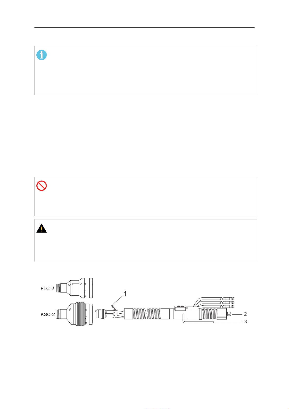
5.4.4.2 RTFLC-2 hollow wrist system with Helix cable assembly
Connecting the nozzle sense function
If the robot control provides a control circuit for nozzle sense functionality.
The connection is accomplished with a 1-wire connection (green) to the nozzle sense circuit
in the robot control (5), see illustration below.
Usually, the control cable will be directly connected to the wire feeder. See the
manufacturer's documentation for details. The link to the robot control is then implemented
via the power source robot interface.
Rating of the control circuit: max. 50 V / 5 A.
NEVARNOST!
If the nozzle sense function is not being used, the open end of the control cable on
the power source connection side must be properly isolated in order to avoid short
circuits. During certain problems on the torch head, the full welding potential may be
present on this cable.
PREVIDNO!
After detection of contact (gas nozzle on work piece), quickly reduce or cut off the
maximum current in the nozzle sense circuit in order to avoid overloading of the
system.
Allowed load max. 1 minute at the rated nominal current.
1 - Control cable plug 3 - EURO central connector
2 - Control cable 4 - Burndy connector
5.5 Torch installation
Be sure to use the correct version of the torch mount and cable assembly (water or gas
cooled).
5.5.1 Torch neck equipment
The torch neck, see (1) in the illustration below, must always be equipped to suit the wire
diameter and material.
0463 373 101
- 46 -
© ESAB AB 2018

5 INSTALLATION
1. Select the correct wire guide, contact tip (4), tip holder (2), gas nozzle (5), and gas
diffuser/spatter protection (3). You will find an exact overview and possible alternative
equipment elements for various torch models in the spare parts list. Only use original
ESAB parts; only then is the fitting accuracy ensured.
2. Firmly tighten the tip holder and the contact tip using a suitable tool for example the
enclosed monkey wrench.
3. When using a split wire guide, remove the installed guide nipple including the o-ring
from the torch flange upon delivery if necessary (see section "Installing the neck
liner").
PREVIDNO!
The torch must be completely equipped before welding, especially the gas
diffuser and/or spatter protection and all necessary insulators have to be
installed according to the spare parts list. Welding without these items may
cause immediate destruction of the torch.
1 - Torch neck 4 - Contact tip
2 - Tip holder 5 - Contact tip
3 - Gas diffuser
5.5.2 Aristo RT torch neck installation
OPOMBA!
Check the O-rings on the flange of the torch neck before mounting. Replace the
O-rings if damaged or lost. Missing or faulty O-rings will lead to leaks of shielding
gas and coolant.
1. For hollow wrist systems, insert the torch into the torch mount in the correct
orientation, so that the locator pin fits into the slot of the RTKSC-2 or RTFLC-2
interface, see (A) in the illustration below. For standard systems, attach the torch to
the RT flange of the cable assembly, (B) in the illustration below.
Installation is only possible in the correct orientation.
2. Tighten the locking nut of the torch neck.
OPOMBA!
Only tighten by hand, never use tools or excessive force.
0463 373 101
- 47 -
© ESAB AB 2018

5 INSTALLATION
3. The correct seating of the torch can be checked by means of the window (1). If the
torch has been correctly mounted, no gap should be seen through the window (1).
5.6 Installing the wire guide for standard and hollow Wrist arm
Installing the wire guide
Choose the wire guide or liner depending on the filler wire material and diameter to be used,
see the spare parts list. Accurate performance of the system can only be guaranteed when
using original ESAB wire guides.
The recommended wire guide is the split wire guide, which consists of the neck liner and a
separate guide in the cable assembly. The front part of the wire guide, which is most
stressed, can be exchanged easily and independently of the cable assembly wire guide.
For correct installation, the following steps must be followed (example for Euro central
connector).
5.6.1 Installing the neck liner
The neck liner must be selected to fit the material and diameter of the welding wire, see the
spare parts list.
0463 373 101
- 48 -
© ESAB AB 2018

5 INSTALLATION
1. If present, remove the central guide nipple (1), from the torch neck using a hexagon
wrench (size 6 mm) or a large flat-blade screwdriver.
OPOMBA!
The guide nipple (1) can only be used with one-piece liners and must not be
used with the standard RT or hollow wrist system.
2. When replacing the neck liner:
Unfasten the sleeve nut and remove the torch neck.
Unfasten the liner nipple using a hexagon wrench (size 6 mm) and remove nipple and
liner from the torch neck.
3. Remove the gas nozzle and the contact tip.
4. Insert the new neck liner (2) into the torch. Carefully tighten the guide nipple using a
suitable tool, e.g. a hex-wrench (size 6 mm) or a large flat-blade screwdriver.
5. Cut the neck liner flush with the tip holder and remove the neck liner from the torch.
6. Install the contact tip.
7. Insert the neck liner again. It will be stopped by the contact tip. Measure the excess
liner sticking out of the neck.
8. Remove the liner again and shorten the front end by the measured length. Carefully
deburr the edge and make sure that the inner hole is not blocked.
9. Reinstall the neck liner and tighten the guide nipple in the neck.
5.6.2 Installing a split wire guide in the cable assembly
The correct liner must be inserted to suit the filler material and the wire diameter, see the
spare parts list.
The wire guide is inserted through the cable assembly from the rear, reaching the guide
nipple that is installed in the flange where the torch neck will be attached. The following
worksteps must be followed in order to correctly determine the wire guide length. (Example
for Euro central connector).
0463 373 101
- 49 -
© ESAB AB 2018

5 INSTALLATION
1. For standard RT system: Install the guide nipple (1) in the center hole of the neck
support flange, see illustration A below.
For hollow wrist system: Install the guide nipple (1) into the torch interface of the
RTKSC-2 / RTFLC-2 cover, see illustration B below.
2. Remove the sleeve nut (2) from the central connector, and remove the old wire guide.
3. Insert the wire guide through the central connection and push forwards as far as it will
go into the guide nipple (1), applying light pressure.
PREVIDNO!
Ensure that the wire guide has advanced right up to the stop at the front,
rotating and pushing forward gently.
4. Measure the excess length that needs to be cut from the wire guide.
5. Remove the wire guide again and shorten the front end by the measured length.
Steel liner: grind down the burred edges if needed.
Plastic liner: make a clean cut and chamfer the edges (e.g. with a pencil sharpener)
OPOMBA!
Make sure the inner opening of the liner is not obstructed by the cut wire end.
0463 373 101
- 50 -
© ESAB AB 2018

5 INSTALLATION
6. Reinstall the wire guide and attach the sleeve nut (2).
OPOMBA!
For hollow wrist systems where Infiniturn and Helix cable assemblies are
used, wire guides should be installed without tension so that the ends of the
liners may rotate freely.
Important note when using a plastic liner:
The wire channel between the drive rolls of the feeder and the central
connector of the torch must be fitted with a plastic liner. Depending on the
design of the feeder, a piece of plastic liner inserted into a brass guide tube
can be used.
During wire run-in, make sure that the wire is fed correctly into the plastic liner
of the torch. If necessary, remove the cable assembly from the feeder and
insert the wire, then reattach.
5.6.3 Installing a continuous wire guide in the cable assembly
Installing a steel liner
The wire guide is inserted through the cable assembly from the rear and reaches to the
contact tip. The following worksteps must be followed for the correct calculation of the length
(example for Euro central connector):
1. Install the torch (see section "Torch neck equipment").
2. Remove the gas nozzle and contact tip from the torch.
3. Remove the sleeve nut (D) from the Euro connector.
4. Push in the liner through the central connector and fix with the sleeve nut.
5. Cut off the liner flush with the nozzle holder. To determine the thread projection of the
contact tip, pull the liner backwards and screw in the contact tip.
6. Push the liner forwards as far as it will go to the contact tip applying light pressure on
the liner and measure the length to be shortened at the rear.
7. Now remove the liner again and cut the excess length measured off it’s front end. If
needed, grind down the burred edges. Make sure the inner opening of the liner is not
obstructed by the cut wire end.
8. The insulation of the liner must be removed after cutting off in the front area, such that
the insulation protrudes out of the RM2 flange by approx. 5 cm. For this, briefly
remove the torch neck.
9. Push the liner back in again and fix with the sleeve nut (D), see above. Re-install the
gas nozzle.
0463 373 101
- 51 -
© ESAB AB 2018

5 INSTALLATION
Installing a plastic liner
1. Mount the torch neck (see section "Torch neck equipment") and equip it with a gas
nozzle and contact tip.
2. Remove the sleeve nut (D) from the Euro connector.
3. Cleanly cut off the liner, slightly break the outer edges, point slightly (e.g. with a pencil
sharpener).
4. Insert the liner through the central connector into the cable assembly with fitted torch.
If it gets stuck, rotate the liner to free it and facilitate installation.
OPOMBA!
Make sure the liner is completely inserted by rotating it and slightly pushing it
forward, until you can feel it has reached its stop.
5. Mount the nipple (B) and the O-Ring (C), move it to the right position and fix it with the
sleeve nut (D) of the Euro central connector.
6. Measure the required overlap needed inside the wire feeder cabinet and cut the liner
accordingly.
5.7 Adjust the narrow gap contact tip
The adjusting tool RT42-NG is designed for the narrow gap torch necks RT42W-NG,
RT42G-NG and RT 82W-0°NG, torches with curved narrow gap contact tip. It facilitates the
precisely repeatable and fast changing of the curved contact tip.
OPOMBA!
The adjusting tool must be securely fastened to a stable base, in order to prevent
the position of the device in relation to the robot cannot change unintentionally. If the
exact orientation of the device is lost, the alignment of the contact tip used for the
elaboration of the welding programs can no longer be reproduced with precision.
Select a position within the operating range of the robot for orientation (alignment) of the
contact tip to the torch. Fasten the adjusting tool firmly to a base using the fastening grooves
provided for this purpose. Fastening material is not included with the adjusting tool. Select
fastening material (screws) to suit the existing conditions.
Save all motion sequences and stop positions required to change or align the wearing parts
to a separate robot program.
Before programming the welding tasks: plan at which orientation the contact tip is to stand in
relation to the torch. The torch must then be positioned in the desired rotational position and
the contact tip aligned using the adjusting device. Only then may the welding task be
programmed. If different orientations of the contact tip are required for various welding tasks,
the contact tip has to be aligned to the new position when the welding task is changed.
POZOR!
The gas nozzle and the torch head become very hot during welding. Always allow
the torch to cool down before replacing wearing parts or adjusting the contact tip.
0463 373 101
- 52 -
© ESAB AB 2018

5 INSTALLATION
Adjust the contact tip
Move the robot torch to a position parallel to
the opening of the adjusting tool (2). Maintain
a sufficient distance to the work table to be
able to comfortably remove the gas nozzle.
Define this position in your robot program as
the wearing parts change position (stop
position 1).
Remove the gas nozzle by pulling it
downwards. Remove the welding wire in the
contact tip if necessary.
Loosen the counter nut (4) of the contact tip
while counter-holding the nozzle holder at the
wrench flat (3).
Unscrew the contact tip including the counter
nut from the nozzle holder and replace the
nozzle holder if necessary.
Completely screw the counter nut (4) onto the
new contact tip. Screw the contact tip
including the counter nut into the nozzle
holder.
Align the contact tip until it is parallel to the
opening of the adjusting tool. If necessary,
slightly unscrew the contact tip so that it can
be easily turned in both directions.
0463 373 101
- 53 -
© ESAB AB 2018

5 INSTALLATION
OPOMBA!
The contact tip must be able to be
easily moved by hand in both
directions in order to enable the
threading of the adjusting tool.
Place the robot torch or contact tip directly in
front of the opening of the adjusting tool (2)
(stop position 2).
Insert it slowly from the front until it is
completely inserted into the device (stop
position 3).
The contact tip was aligned exactly in the
device during insertion. Now cautiously
tighten the counter nut (4) in this position,
while counter holding the nozzle holder at the
wrench flat.
Slowly move the robot torch out of the
adjusting gauge, return to stop position 1 and
push on the gas nozzle as far as it will go.
Allow the welding wire to run into the contact
tip and bring the robot arm into welding
position.
0463 373 101
- 54 -
© ESAB AB 2018

6 OPERATION
6 OPERATION
PREVIDNO!
Before starting the system, check the whole installation according to the
manufacturer's instructions and applicable safety regulations.
Check the following to make sure that the system has been installed correctly:
1. Are all parts securely attached (torch, torch mount, flanges, safety-off device, cable
assembly, and wire feeder cabinet)?
2. Are all media hoses connected correctly and protected from damage?
3. Is the EURO central connector or direct connector fastened tightly?
4. Is the cable assembly length correct and suitable for the installation and can the cable
rotate freely? The cable must not be bent sharply. Any risk of the cable getting caught
on another object must be eliminated.
5. Is the control cable of the safety-off circuit connected and functioning? Move torch by
hand to test (RTKSC-2 and RTKS-2 only).
6. Is the torch firmly attached and is it completely equipped?
7. Is the wire guide installed according to the manual?
8. Are all lines and tubes arranged so that they cannot be damaged or bent?
The wire run-in can now be started, either via the wire run-in pushbutton or via the wire run-in
at the feeder.
6.1 Important information for programming (hollow wrist system only)
Fast rotation of axis 6 of the robot will significantly stress the cable assembly. In certain
cases, this can lead to damage or destruction of the cable. In order to maximize the lifetime
of the cable, we strongly suggest respecting the following limitations when programming the
robot.
Position of axis 5 Max. rotational speed of axis 6
0 – 60° 100 % (no limitations)
60° – 80° 300°/sec (approximately 50 % of max. robot speed)
> 80° 120°/sec (approximately 20 % of max. robot speed)
OPOMBA!
The above values are only indications. For information on the exact rotational speed
limits, refer to the individual robot manual or contact the robot supplier.
To reposition the torch quickly, the robot arm may have to be slightly extended first to achieve
a bending angle of max. 60° of axis 5. In this position, the maximum available rotation speed
of axis 6 can be used.
When using the ESAB Helix cable assembly, the max. rotation of ±270° from the neutral
position must not be exceeded.
0463 373 101
- 55 -
© ESAB AB 2018

6 OPERATION
PREVIDNO!
While axis 5 is bent more than 60°, the rotational speed of the torch around axis 6
must be limited, see table above.
Otherwise, the cable assembly may be damaged.
0463 373 101
- 56 -
© ESAB AB 2018
7 SERVIS IN VZDRŽEVANJE
7 SERVIS IN VZDRŽEVANJE
POZOR!
Pred vzdrževanjem sistema je treba odklopiti napajanje. Preberite varnostne
predpise na začetku teh navodil.
Poškodovanih gorilnikov ali sklopov kablov ne smete uporabljati. Znane okvare
mora pred naslednjo uporabo sistema popraviti usposobljeno osebje.
POZOR!
Nevarnost opeklin! Šoba za plin in glava gorilnika se med varjenjem zelo segrejeta.
Počakajte, da se gorilnik ohladi, preden se lotite vzdrževanja.
POZOR!
Z upoštevanjem teh navodil lahko preprečite telesne poškodbe ali škodo na opremi:
1. Popravilo nosilca gorilnika RT KSC-2 ali RT FLC-2, mehanizma
varnostnega izklopa RT KS-2, sklopa kablov ali priključka za sredstva
Infiniturn lahko izvede samo servisna služba družbe ESAB.
2. Priključka za sredstva Infiniturn ne smete odpirati. Vsebuje dele, ki jih
uporabnik ne more servisirati in jih boste z razstavljanjem uničili.
3. Ne razstavljajte nosilca RT KSC-2 ali mehanizma RT KS-2. Mehanizem je
vzmeten. Neustrezni posegi lahko povzročijo težke poškodbe.
7.1 Obvezni pregledi in ukrepi
Pred vsako uporabo:
• Preglejte morebitne splošne poškodbe na gorilniku, kontaktni konici, šobi za plin, oblogi
vratu in vsej opremi.
OPOMBA!
Čas nedelovanja skrajšate tako, da izmenično uporabljate dva vratova gorilnika in
imate vedno pri roki na novo opremljen vrat gorilnika.
Vsakih 8 ur uporabe (odvisno od namena uporabe):
• Zamenjajte kontaktno konico.
Vsak dan:
• Z roko preglejte delovanje mehanizma varnostnega izklopa.
• Vizualno si oglejte morebitno škodo, npr. upogibanja in razpoke.
• Preverite, ali je podajalnik žice v ustreznem položaju. Sklop kablov ne sme biti preveč
napet ali preveč razrahljan.
• Preverite, ali priključek za sredstva Infiniturn in drugi priključki za sredstva morda
puščajo.
• Čistite in vzdržujte gorilnik v skladu z navodili za uporabo gorilnika.
Vsakih 40 ur uporabe (odvisno od namena uporabe):
• Zamenjajte vodila žic.
• Zamenjajte obloge vratov.
Vsak teden ali po potrebi glede na uporabo:
0463 373 101
- 57 -
© ESAB AB 2018

7 SERVIS IN VZDRŽEVANJE
• Odstranite vodilo žice in preglejte, ali je morda obrabljeno in umazano. Po potrebi ga
zamenjajte
Vsak mesec ali pogosteje ob intenzivni uporabi (več kot 8 ur dnevno):
• Izpihajte kanal za vodilo žice s stisnjenim zrakom (odstranite kontaktno konico in vodilo
žice).
• Prepričajte se, da so vsi vijaki priviti.
• Preglejte morebitne poškodbe povezav in cevi.
• Zamenjajte vseh 250kg varilne žice.
Škodo na električni izolaciji mora popraviti usposobljeno osebje, preden lahko sistem varno
uporabljate.
0463 373 101
- 58 -
© ESAB AB 2018
8 ODPRAVLJANJE NAPAK
8 ODPRAVLJANJE NAPAK
Napaka Možen vzrok Ukrep
Podajanje žice
je
onemogočeno
Varilna žica ni bila poravnana,
preden ste jo podali v sklop kablov
Gorilnik in sklop kablov nista
ustrezno opremljena za premer in
material žice
Vodilo žice ni pravilno vstavljeno v
sklop kablov
Kontaktna konica je zamašena z
ostanki žice
Vodilo žice je obrabljeno
Podajanje žice ovirajo umazanija in
ostanki v gorilniku
Po potrebi znova izvlecite varilno
žico, jo odrežite in zgladite na koncu
ter poravnajte prvih 10cm žice.
Nato jo napeljite nazaj v sklop
kablov.
Preglejte vodilo žice (sklop kablov in
vrat gorilnika) in kontaktno konico.
Vodilo žice nekoliko izvlecite iz
EURO-priključka. Pri vstavljanju
vodila žice morate čutiti, kako
zadnjih nekaj centimetrov zdrsne v
nastavek vodila v vmesniku
gorilnika. V nasprotnem primeru je
vodilo žice morda prekratko in ni
vstavljeno do konca.
Zamenjajte kontaktno konico in/ali
vodilo žice, izpihajte vrat gorilnika,
cev vodila žice in vodilo žice s
stisnjenim zrakom.
Gorilnik se
preveč segreva
Težave pri
podajanju žice
Kontaktna konica ali držalo konice
nista ustrezno privita
Z roko in ustreznim orodjem ju
privijte.
Hladilni sistem ne deluje pravilno Preverite pretok vode, raven
napolnjenosti in čistočo.
Hladilni sistem ni pravilno priključen Preglejte priključke (dovodno in
povratno odprtino za vodo).
Prenapet gorilnik Oglejte si tehnične podatke in po
potrebi izberite drugo vrsto.
Pokvarjen kabelski sestav Preglejte kable, cevi in priključke.
Kontaktna konica je obrabljena Zamenjajte kontaktno konico.
Vodilo je obrabljeno/umazano Preglejte vodilo; izpihajte. Po
potrebi ga zamenjajte
Uporabljen potrošni material ni
primeren za premer ali material žice
Podajalnik žice ni pravilno
nastavljen
Sklop kablov je upognjen ali
napeljan v premajhnem radiju
Oglejte si seznam nadomestnih
delov.
Preglejte valjčke za podajanje žice,
kontaktni tlak in zavoro za tuljavo.
Preglejte morebitno škodo na
sklopu kablov. Je vodilo mogoče
zlahka vstaviti? Vstavite ga po
navodilih. Glejte poglavje »Montaža
sklopa kablov«.
0463 373 101
Žica je onesnažena Uporabite čistilno klobučevino.
- 59 -
© ESAB AB 2018

8 ODPRAVLJANJE NAPAK
Napaka Možen vzrok Ukrep
Podajanje žice
Tuljava z žico je prazna Preglejte količino varilne žice na
se med
varjenjem
Blokada žice v sklopu kablov Preglejte postopek podajanja žice
zaustavi
Odgorevanje žice v kontaktni konici
ali obrabljena kontaktna konica
Postopek
varjenja se
Sprožil se je mehanizem
varnostnega izklopa.
prekinja
Pore v spojih Vrtinčenje plina, ki ga povzročijo
okruški
Premajhen ali izjemno visok pretok
plina v gorilniku
Pokvarjen dovod plina Preverite hitrost pretoka in
Vlaga ali onesnaženost na žici ali
obdelovancu
tuljavi v podajalniku žice.
(morda je prehitro), preglejte, ali je
kontaktna konica
onesnažena/zamašena in jo po
potrebi očistite ali zamenjajte.
Zamenjajte kontaktno konico.
Poiščite točke trčenja in jih
odpravite. Preverite, ali je v
krmilnem vodu slab stik.
Očistite glavo gorilnika, uporabite
difuzor plina/zaščito proti
odkruškom.
Preverite hitrost pretoka z merilnim
orodjem.
morebitna uhajanja.
Preverite žico in obdelovanec,
uporabite manj tekočine ali drugo
tekočino proti okruškom.
Oblok ni
stabilen
Kontaktna konica je obrabljena Zamenjajte kontaktno konico.
Napačni varilni parametri Preglejte namestitev varilne
opreme.
Pomanjkljive električne povezave v
vezju
Preglejte, ali so vse električne
povezave (vključno z ozemljitvenim
kablom) med varilnim
transformatorjem in obdelovancem
dobro priključene.
0463 373 101
- 60 -
© ESAB AB 2018

9 NAROČANJE NADOMESTNIH DELOV
9 NAROČANJE NADOMESTNIH DELOV
PREVIDNO!
Popravila in električna dela naj opravlja pooblaščeni ESAB-ov serviser. Uporabljajte
izključno originalne ESAB-ove nadomestne in obrabne dele.
Gorilniki ESAB RTKS-2, RTFL-2, RT-KSC-2, RT-FLC-2, RT42, RT52, RT62, RT72,
RT82, RT42-NG in RT82WNG so zasnovani in testirani v skladu z mednarodnimi in
evropskimi standardi IEC/EN 60974-7. Servisna delavnica, ki je opravila servis ali popravilo,
mora preveriti in zagotoviti, da je izdelek še vedno skladen z navedenim standardom.
Nadomestne in obrabne dele lahko naročite pri najbližjem predstavniku proizvajalca ESAB –
glejte esab.com. Pri naročanju navedite tip in serijsko številko izdelka ter oznako in številko
nadomestnega dela po seznamu nadomestnih delov. S tem poenostavite dobavo in si
zagotovite, da bo pravilna.
0463 373 101
- 61 -
© ESAB AB 2018

ESAB AB, Lindholmsallén 9, Box 8004, 402 77 Gothenburg, Sweden, Phone +46 (0) 31 50 90 00
http://manuals.esab.com
For contact information visit esab.com
 Loading...