

RT Robo Welding Torch System
RTKS-2, RTFL-2, KSC-2, FLC-2, RT42, RT52,
RT62, RT72, RT82, RT42-NG, RT82WNG
Lietošanas pamācība
0463 373 101 LV 20181227


SATR-TRS
1
DROŠĪBA..................................................................................................... 5
1.1 Simbolu nozīme...................................................................................... 5
1.2 Drošības pasākumi ................................................................................ 5
2
GARANTIJA ................................................................................................ 8
2.1 Paredzētās lietošanas nosacījumi ........................................................ 8
3
IEVADS ........................................................................................................ 9
3.1 Metināšanas degļu sistēmu pārskats................................................... 10
4
TEHNISKIE DATI ......................................................................................... 12
4.1 Metināšanas degļa kakls ....................................................................... 12
4.2 Sprieguma nominālie parametri............................................................ 13
4.2.1 Dzesēšanas kontūra robežvērtības...................................................... 13
4.3 Degļa stiprinājums ................................................................................. 14
4.3.1 Degļa stiprinājumi standarta RT sistēmai ............................................. 14
4.3.1.1 RTKS-2 aizsargizslēgšanas mehānisms .......................................... 15
4.3.1.2 RTFL-2 vidējais atloks ...................................................................... 15
4.3.2 Degļa stiprinājumi dobā satvērēja sistēmai .......................................... 15
4.3.2.1 RTKSC-2 G/W degļa stiprinājums ar aizsargizslēgšanas
mehānismu........................................................................................
4.3.2.2 RTFLC-2 G/W nekustīgais degļa stiprinājums ................................. 18
4.4 Adaptera atloki ....................................................................................... 19
4.5 Kabeļa bloki ............................................................................................ 19
4.5.1 Kabeļa bloki standarta RT sistēmai ...................................................... 19
4.5.2 Kabeļa bloki dobā satvērēja sistēmām................................................. 20
5
INSTALLATION............................................................................................ 22
5.1 RTKS-2 standard arm installation........................................................ 22
5.1.1 RTKS-2 safety-off mechanism............................................................. 22
5.1.1.1 Torch installation with adjustable mount............................................ 23
5.1.2 Standard arm cable assembly for KS-2 and FL-2 ................................ 25
5.1.3 RTKS-2 wire feeder connection........................................................... 26
5.1.4 RTKS-2 electrical connections ............................................................ 27
5.1.4.1 RTKS-2 safety-off mechanism connection ....................................... 27
5.1.5 RTKS-2 Torch installation.................................................................... 28
5.2 RTFL-2 standard arm installation ........................................................ 29
17
5.2.1 RTFL-2 rigid mount.............................................................................. 29
5.2.2 RTFL-2 torch installation ..................................................................... 31
5.3 RTKSC-2 hollow wrist system installation.......................................... 31
5.3.1 RTKSC-2 mount with safety off mechanism........................................ 31
5.3.2 Mounting the cable assembly............................................................... 32
5.3.2.1 RTKSC-2 feeder cabinet connections .............................................. 33
5.3.3 RTKSC-2 cable assembly ................................................................... 35
5.3.3.1 RTKSC-2 cable assembly installation .............................................. 35
0463 373 101 © ESAB AB 2018

SATR-TRS
5.3.3.2 RTKSC-2 electrical connections....................................................... 38
5.3.4 RTKSC-2 torch installation .................................................................. 39
5.4 RTFLC-2 installation.............................................................................. 40
5.4.1 RTFLC-2 mount................................................................................... 40
5.4.2 RTFLC-2 wire feeder connection......................................................... 40
5.4.2.1 Feeding through the robot arm.......................................................... 40
5.4.2.2 RTFLC-2 feeder cabinet connections............................................... 41
5.4.3 RTFLC-2 cable assembly .................................................................... 43
5.4.3.1 RTFLC-2 cable assembly installation ............................................... 43
5.4.4 RTFLC-2 electrical connections .......................................................... 46
5.4.4.1 RTFLC-2 hollow wrist system with Infiniturn cable assembly........... 46
5.4.4.2 RTFLC-2 hollow wrist system with Helix cable assembly................. 47
5.5 Torch installation.................................................................................... 47
5.5.1 Torch neck equipment .......................................................................... 47
5.5.2 Aristo RT torch neck installation ........................................................... 48
5.6 Installing the wire guide for standard and hollow Wrist arm ............. 49
5.6.1 Installing the neck liner......................................................................... 49
5.6.2 Installing a split wire guide in the cable assembly................................ 50
5.6.3 Installing a continuous wire guide in the cable assembly..................... 52
5.7 Adjust the narrow gap contact tip ........................................................ 53
6
OPERATION ................................................................................................ 56
6.1 Important information for programming (hollow wrist system only) 56
7
SERVISS UN APKOPE................................................................................ 58
7.1 Obligātās pārbaudes un darbības ........................................................ 58
8
TRAUCĒJUMMEKLĒŠANA ........................................................................ 60
9
REZERVES DAĻU PASŪTĪŠANA............................................................... 62
Tiek paturētas tiesības bez brīdinājuma veikt izmaiņas specifikācijās.
0463 373 101 © ESAB AB 2018

1 DROŠĪBA
1 DROŠĪBA
1.1 Simbolu nozīme
Izmantoti šajā rokasgrāmatā: Uzmanību! Ievērojiet piesardzību!
BĪSTAMI
Apzīmē tūlītēju apdraudējumu, kas, ja netiek novērsts, izraisa nopietnas vai
nāvējošas traumas.
BRĪDINĀJUMS!
Apzīmē iespējamu apdraudējumu, kas var izraisīt traumas vai nāvi.
UZMANĪBU!
Apzīmē apdraudējumu, kas var izraisīt vieglas traumas.
BRĪDINĀJUMS!
Pirms iekārtas lietošanas izlasiet un izprotiet lietošanas
instrukciju, kā arī ievērojiet visās uzlīmēs sniegtos
norādījumus, darba devēja noteiktos drošības
pasākumus un drošības datu lapās (Safety Data
Sheets— SDS) norādīto informāciju.
1.2 Drošības pasākumi
ESAB iekārtas lietotāji pilnībā atbild par to, lai tiktu nodrošināts, ka visi, kas strādā ar iekārtu
vai pie tās, ievērotu visus attiecīgos drošības pasākumus. Drošības pasākumiem jāatbilst
prasībām, kas attiecas uz šī tipa iekārtām. Papildus standarta noteikumiem, kas attiecas uz
darba vietu, jāievēro šādi ieteikumi.
Visus darbus veic kvalificēts personāls, kas labi pārzina iekārtas darbību. Nepareizi
ekspluatējot iekārtu, var rasties bīstamas situācijas, kuru dēļ iekārtas operators var gūt
ievainojumus un iekārtu var sabojāt.
1. Visiem, kas lieto iekārtu, jāpārzina:
○ tās darbība;
○ kur atrodas avārijas slēdži;
○ iekārtas funkcijas;
○ attiecīgie drošības pasākumi;
○ metināšana un griešana vai citas ar iekārtu veicamās darbības.
2. Operatoram jānodrošina, lai:
○ neviena nepiederoša persona iedarbināšanas brīdī neatrodas iekārtas darbības
zonā;
○ neviens nav neaizsargāts, kad rodas elektriskais loks vai tiek sākts darbs ar
iekārtu.
3. Darba vietā:
○ jābūt metināšanai piemērotiem apstākļiem;
○ nedrīkst būt caurvējš.
0463 373 101
- 5 -
© ESAB AB 2018

1 DROŠĪBA
4. Individuālās aizsardzības līdzekļi:
○ Vienmēr lietojiet ieteiktos drošības līdzekļus, piemēram, aizsargbrilles,
ugunsdrošu apģērbu, aizsargcimdus
○ Nevalkājiet nepieguļošus aksesuārus, tādus kā šalles, rokassprādzes,
gredzenus utt., kas var aizķerties vai radīt apdegumus
5. Vispārīgi drošības pasākumi:
○ Pārliecinieties, vai atpakaļstrāvas kabelis ir pievienots droši
○ Darbu ar augstsprieguma iekārtu drīkst veikt tikai kvalificēts elektriķis
○ Piemērotai ugunsdzēšanas iekārtai jābūt skaidri apzīmētai un jāatrodas ļoti tuvu
○ Eļļošanu un apkopi nedrīkst veikt iekārtas darbības laikā
BRĪDINĀJUMS!
Loka metināšana un griešana var radīt traumas jums un citām personām.
Metināšanas un griešanas laikā ievērojiet drošības pasākumus.
ELEKTROŠOKS— bīstams dzīvībai
• Uzstādiet un iezemējiet iekārtu atbilstoši lietošanas instrukcijai.
• Nepieskarieties elektrību vadošajām daļām un elektrodiem ar kailu ādu,
slapjiem cimdiem vai slapju apģērbu.
• Izolējiet sevi no darba materiāla un zemes.
• Strādājiet drošā pozā.
ELEKTROMAGNĒTISKIE LAUKI— var būt kaitīgi veselībai
• Metinātājiem, kuriem ir elektrokardiostimulators, pirms metināšanas ir
ieteicams konsultēties ar ārstu. Elektromagnētiskie lauki (EML) var izraisīt
elektrokardiostimulatora darbības traucējumus.
• EML var izraisīt arī citu, pagaidām nezināmu ietekmi uz veselību.
• Metinātājiem jāveic tālāk minētās darbības, lai mazinātu iespēju tikt
pakļautiem EML ietekmei.
○ Izvelciet elektrodu un darba kabeļus tā, lai tie būtu jums vienā pusē.
Ja iespējams, nostipriniet kabeļus ar līmlenti. Uzmanieties, lai jūsu
ķermenis neatrastos starp metināšanas degli un darba kabeļiem.
Nekādā gadījumā neapvijiet metināšanas degli vai darba kabeli ap
sevi. Turiet metināšanas strāvas avotu un kabeļus pēc iespējas tālāk
no sevis.
○ Pievienojiet darba kabeli sagatavei pēc iespējas tuvāk metināšanas
apgabalam.
DŪMI UN GĀZES— var būt kaitīgi veselībai
• Neturiet galvu dūmos.
• Lai aizvadītu dūmus un gāzes no elpošanas zonas un apkārtējās
teritorijas, ieslēdziet ventilāciju, nosūcēju pie loka vai abus.
LOKA STARI - var savainot acis un apdedzināt ādu
0463 373 101
• Sargājiet acis un ķermeni. Lietojiet piemērotu metināšanas masku un
aizsarglēcas un nēsājiet aizsargapģērbu.
• Aizsargājiet blakus esošās personas ar piemērotām maskām vai
aizslietņiem.
TROKSNIS— pārmērīgs troksnis var bojāt dzirdi
Sargājiet ausis. Lietojiet austiņas vai citus dzirdes aizsarglīdzekļus.
- 6 -
© ESAB AB 2018

1 DROŠĪBA
KUSTĪGAS DAĻAS— var izraisīt savainojumus
• Visām durvīm, paneļiem un pārsegiem jābūt aizvērtiem un nostiprinātiem.
Tikai kvalificēti darbinieki drīkst noņemt pārsegus, lai nepieciešamības
gadījumā veiktu apkopi un remontu. Pēc apkopes pabeigšanas uzstādiet
atpakaļ paneļus vai pārsegus un aizveriet durvis, pirms iedarbināt dzinēju.
• Pirms ierīces uzstādīšanas vai pievienošanas izslēdziet dzinēju.
• Kustīgu daļu tuvumā nedrīkst atrasties rokas, mati, vaļīgs apģērbs un rīki.
UGUNSBĪSTAMĪBA
• Dzirksteļu dēļ var izcelties ugunsgrēks. Pārliecinieties, vai tuvumā nav
viegli uzliesmojošu materiālu.
• Neizmantojiet iekārtu darbam ar slēgtām tvertnēm.
DARBĪBAS TRAUCĒJUMI— rodoties darbības traucējumiem, meklējiet profesionālu
palīdzību
SARGĀJIET SEVI UN CITUS!
UZMANĪBU!
Šis produkts paredzēts tikai elektriskā loka metināšanai.
BRĪDINĀJUMS!
Neizmantojiet barošanas avotu, lai atkausētu sasalušas caurules.
UZMANĪBU!
A klases iekārtas nav paredzētas lietošanai dzīvojamās
mājās, kurās elektriskā strāva tiek piegādāta, izmantojot
publisko zemsprieguma elektrotīklu. Šādās vietās var
būt grūtības nodrošināt A klases iekārtu
elektromagnētisko saderību, ņemot vērā pārvades un
starojuma izraisītos traucējumus.
IEVĒROJIET!
Utilizējiet elektronisko aprīkojumu, nododot to
otrreizējās pārstrādes punktā!
Ievērojot Eiropas Direktīvu 2012/19/EK par elektriskā un
elektroniskā aprīkojuma atkritumiem un īstenojot to
saskaņā ar valsts tiesību aktiem, elektriskās un/vai
elektroniskās iekārtas, kam beidzies kalpošanas laiks,
jānodod utilizācijai otrreizējās pārstrādes punktos.
Kā par iekārtu atbildīgajai personai, jums ir pienākums
iegūt informāciju par apstiprinātajām savākšanas
vietām.
Lai iegūtu plašāku informāciju, sazinieties ar tuvāko
ESAB izplatītāju.
ESAB piedāvā iegādāties dažādas metināšanas piederumu un personiskās
aizsardzības aprīkojuma preces. Lai saņemtu informāciju par pasūtīšanu, sazinieties
ar vietējo ESAB izplatītāju vai apmeklējiet mūsu uzņēmuma tīmekļa vietni.
0463 373 101
- 7 -
© ESAB AB 2018

2 GARANTIJA
2 GARANTIJA
Pirms piegādes mūsu produkti tiek rūpīgi pārbaudīti. ESAB apliecina, ka piegādes brīdī
nevienam produktam nav materiāla vai izgatavošanas defektu un tas darbojas atbilstoši
paredzētajam lietošanas mērķim.
ESAB nodrošina garantiju materiālu un izgatavošanas defektu gadījumā atbilstoši
likumdošanas normu prasībām. Garantija neattiecas uz palīgmateriāliem.
Garantija nav spēkā, ja bojājumi vai darbības traucējumi radušies šādu iemeslu dēļ:
• produkta pārslogošana, nepareiza ekspluatācija vai mērķim neatbilstoša lietošana;
• triecieni vai negadījumi;
• šajā lietošanas instrukcijā sniegto norādījumu neievērošana;
• nepareiza uzstādīšana vai montāža;
• nepietiekama apkope;
• produkta oriģinālā stāvokļa pārveidošana;
• ķīmisku vielu ietekme;
• normāls nodilums un nolietošanās.
ESAB uzņemas atbildību tikai par bojātu daļu nomaiņu vai remontu.
2.1 Paredzētās lietošanas nosacījumi
1. Produkts ir paredzēts rūpnieciskai un komerciālai lietošanai, un to drīkst izmantot tikai
apmācīts personāls. Ražotājs nav atbildīgs ne par kādiem bojājumiem vai
negadījumiem, kas radušies nepareizas lietošanas dēļ.
2. Aristo® RT robotizētā metināšanas sistēma ir izstrādāta un izgatavota atbilstoši
mūsdienu tehnikas attīstības līmenim, un tās darbība ir droša un uzticama, ja ar to
rīkojas, to uzstāda un apkopi veic apmācīts personāls. Ir jāievēro uzstādīšanas,
lietošanas un apkopes norādījumi, kas aprakstīti šajā dokumentā.
3. Aristo® RT robotizēto metināšanas sistēmu drīkst uzstādīt, lietot un apkopt tikai
apmācīts personāls. Ir jāievēro šajā rokasgrāmatā detalizēti aprakstītie uzstādīšanas,
lietošanas un apkopes noteikumi.
4. Aristo® RT robotizēto metināšanas sistēmu drīkst lietot tikai ražotāja norādītajam
mērķim, ievērojot sistēmas tehniskos datus un izmantojot automatizētas apstrādes
sistēmas. Degļa tips jāizvēlas atbilstoši metināšanas uzdevumam.
5. Aristo® RT robotizētā metināšanas sistēma ir izstrādāta lietošanai kā pilnībā
komplektēta sistēma. Citu ražotāju izgatavotu komponentu iebūvēšana sistēmā nav
atļauta.
6. RT KS-2 un RT KSC-2 ir paredzēti izmantošanai tikai kā avārijas apturēšanas
mehānismi, ievērojot tehniskās specifikācijas un kombinācijā ar RT standarta sviras
kabeļa bloku (KS-2), Infiniturn vai Helix (KSC-2), ESAB adaptera atloku kopā ar RT
degļa stiprinājumiem (KS-2) un Aristo RT metināšanas degli.
7. Izpūtes gāzei nedrīkst pievienot eļļu vai pretšļakstu šķidrumu. ESAB negarantē
ķīmisko izturību pret šīm vielām. ESAB iesaka izmantot ESAB smidzināšanas ierīci, lai
padotu deglim minimālo daudzumu pretšļakstu šķidruma un tādējādi aizsargātu
apkārtējo vidi.
8. Transportēšanas, glabāšanas un lietošanas laikā produkts jātur sausumā un jāsargā
no mitruma.
9. Sistēma ir paredzēta vides temperatūrai diapazonā no 5°C līdz 40°C (41°F līdz
104°F). Ja šīs robežvērtības tiek pārsniegtas, ir nepieciešama īpaša rīcība. Sala riska
gadījumā lietojiet piemērotu dzesēšanas šķidrumu.
0463 373 101
- 8 -
© ESAB AB 2018

3 IEVADS
3 IEVADS
RT metināšanas degļu sistēmas ir izstrādātas pilnībā automātiskai MIG/MAG metināšanai,
izmantojot robotus. Sistēma sastāv no dažādiem Aristo RT degļa kakliem, kas paredzēti
robotizētai lietošanai, degļa stiprinājumiem, kabeļa blokiem, kas optimizēti robotizētai
lietošanai, un aizsargizslēgšanas funkcijām, lai nepieļautu sistēmas bojājumus sadursmes
gadījumā.
Standarta RT metināšanas sistēma nodrošina aizsardzību pret sadursmēm, izmantojot
RTKS-2, kas ir mehāniska, ar atsperi darbināma aizsargizslēgšanas funkcija. Pēc izvēles to
var aizstāt ar RTFL-2, lai izmantotu robota vadības sistēmas nodrošinātās sadursmes
noteikšanas funkcijas priekšrocības. Standarta RT metināšanas sistēmu var izmantot ar
dažādiem kabeļa bloku tipiem.
RTKSC-2 un RTFLC-2 degļu stiprinājumi ar Infiniturn vai Helix kabeļa blokiem ir paredzēti
lietošanai ar dobā satvērēja robotizētajām metināšanas sistēmām, kas izstrādātas
sarežģītiem metināšanas lietojumiem. Aizsargizslēgšanas mehānisms RTKSC-2 degļa
stiprinājumā nodrošina plašu, elastīgu degļa nolieci sadursmes gadījumā. Infiniturn un Helix
kabeļa bloki ir viegli uzstādāmi un nodrošina augstu sistēmas uzticamību un precīzas
manevrēšanas spēju.
Kombinācijā ar vispāratzītajiem RT robotizētajiem metināšanas degļiem šīs sastāvdaļas
veido ļoti uzticamu un ilgtspējīgu sistēmu, kam nepieciešama tikai minimāla apkope.
Šī lietošanas rokasgrāmata ir iekļauta degļa stiprinājumu un kabeļa bloku piegādes
komplektācijā.
ESAB pasūtījuma numuri, pieejamie piederumi, rezerves daļas un dilstošās daļas ir
atrodamas rezerves daļu sarakstā.
0463 373 101
- 9 -
© ESAB AB 2018

3 IEVADS
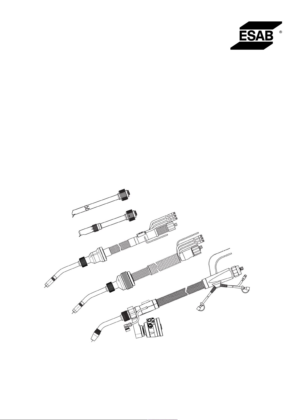
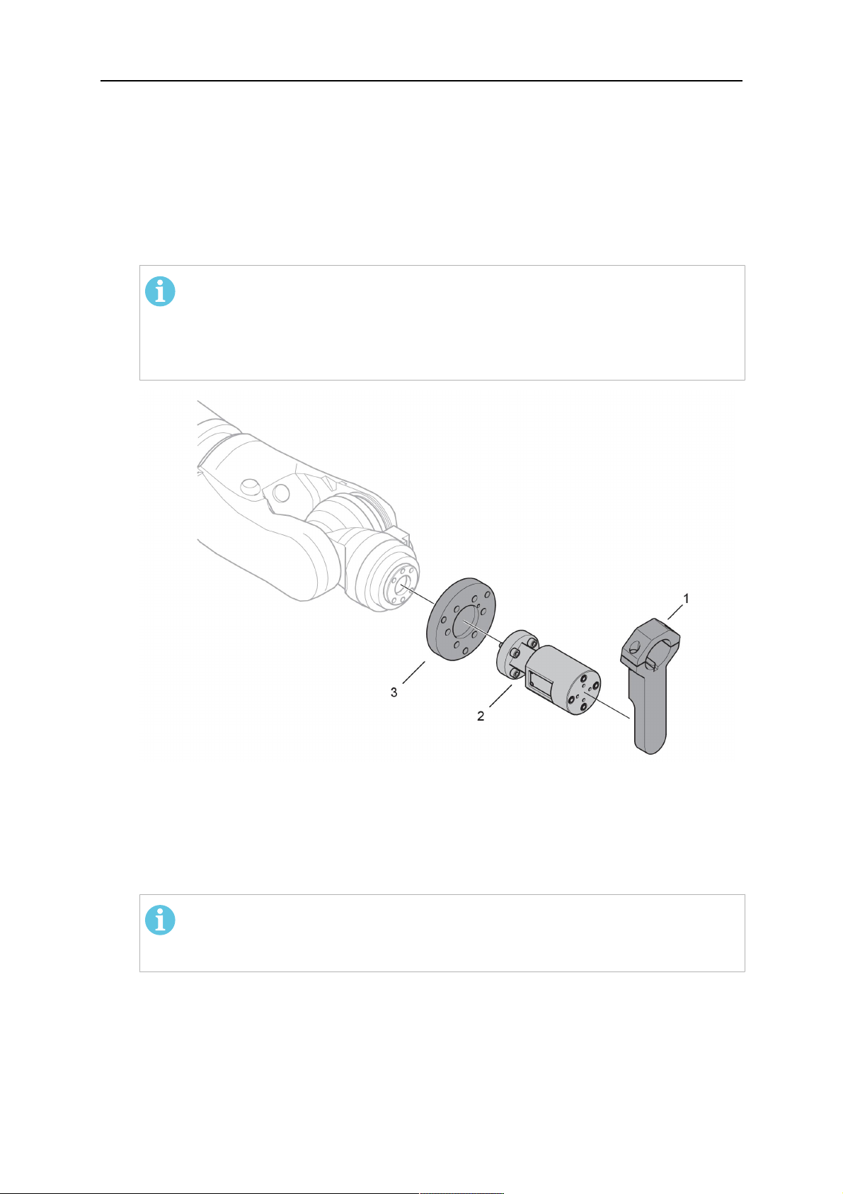
3.1 Metināšanas degļu sistēmu pārskats
Standarta RT sistēma
Detalizētu aprakstu skatiet nodaļas
TEHNISKIE DATI atbilstošajā sadaļā.
1. Degļa kakls
Skatiet sadaļu "Metināšanas deglis".
2. Kabeļa bloks
Skatiet "Kabeļa bloki standarta RT
sistēmai".
3. Degļa stiprinājums
Skatiet sadaļu "Degļa stiprinājumi
standarta RT sistēmai".
4. RTKS-2 aizsargizslēgšanas
mehānisms
Skatiet sadaļu "RTKS-2
aizsargizslēgšanas mehānisms".
5. RTFL-2 vidējais atloks
Skatiet sadaļu "RTFL-2 vidējais
atloks".
6. Adaptera atloks (ja nepieciešams)
Skatiet sadaļu "Adaptera atloki".
0463 373 101
- 10 -
© ESAB AB 2018
3 IEVADS
Dobā satvērēja sistēma
Detalizētu aprakstu skatiet nodaļas
TEHNISKIE DATI atbilstošajā sadaļā.
1. Degļa kakls
Skatiet sadaļu "Metināšanas deglis".
2. Degļa stiprinājums RTKSC-2
Skatiet sadaļu "RTKSC-2 degļa
stiprinājums ar aizsargizslēgšanas
mehānismu".
3. Degļa stiprinājums RTFLC-2
Skatiet sadaļu "RTFLC-2
nekustīgais degļa stiprinājums".
4. Adaptera atloks
Skatiet sadaļu "Adaptera atloki".
5. Kabeļa bloki Helix vai Infiniturn
Skatiet "Kabeļa bloki dobā satvērēja
sistēmām".
0463 373 101
- 11 -
© ESAB AB 2018

4 TEHNISKIE DATI
4 TEHNISKIE DATI
4.1 Metināšanas degļa kakls
Izvēlieties degļa modeli atbilstoši metināšanas lietojumam. Jāņem vērā nepieciešamais
darba režīma cikls un jauda, dzesēšanas veids un stieples diametrs. Ja pastāv
paaugstinātas prasības, piemēram, iepriekš uzkarsēts apstrādājamais priekšmets, liels
karstuma atstarojums stūros, tās ir jāņem vērā, un jāizvēlas metināšanas deglis ar atbilstošu
nominālās slodzes rezervi.
RT metināšanas degļi ir paredzēti lietošanai ar CE prasībām atbilstošiem metināšanas
barošanas avotiem metāla inerto gāzu (MIG) metināšanas, metāla aktīvo gāzu (MAG)
metināšanas un MIG cietlodēšanas procesos ar rūpnieciskajām apaļajām stieplēm.
Neizmantojiet degli citiem procesiem.
Tērauda impulsa loka metināšanai vai alumīnija metināšanai jāizmanto RT82W deglis ar
ūdens dzesēšanu.
Pieejamos degļa modeļus skatiet tālāk.
Degļa modelis Dzesēšanas veids Ekranējošā gāze Nominālie parametri
RT42G Dzesēšana ar gāzi CO
Dzesēšana ar gāzi 300A/100%
Dzesēšana ar gāzi Maisījums 350A/60%
Dzesēšana ar gāzi 250A/100%
RT42W Dzesēšana ar ūdeni CO
Dzesēšana ar ūdeni 420A/100%
Dzesēšana ar ūdeni Maisījums 350A/60%
Dzesēšana ar ūdeni 350A/100%
RT52G Dzesēšana ar gāzi CO
Dzesēšana ar gāzi 300A/100%
Dzesēšana ar gāzi Maisījums 350A/60%
Dzesēšana ar gāzi 250A/100%
RT52W Dzesēšana ar ūdeni CO
Dzesēšana ar ūdeni 470A/100%
Dzesēšana ar ūdeni Maisījums 400A/60%
Dzesēšana ar ūdeni 400A/100%
RT62G Dzesēšana ar gāzi CO
Dzesēšana ar gāzi 340A/100%
2
2
2
2
2
420A/60%
420A/60%
420A/60%
470A/60%
500A/60%
Dzesēšana ar gāzi Maisījums 420A/60%
Dzesēšana ar gāzi 290A/100%
RT62W Dzesēšana ar ūdeni CO
Dzesēšana ar ūdeni 530A/100%
Dzesēšana ar ūdeni Maisījums 450A/60%
Dzesēšana ar ūdeni 450A/100%
0463 373 101
- 12 -
2
530A/60%
© ESAB AB 2018
4 TEHNISKIE DATI
Degļa modelis Dzesēšanas veids Ekranējošā gāze Nominālie parametri
RT72G Dzesēšana ar gāzi CO
2
480A/60%
Dzesēšana ar gāzi 320A/100%
Dzesēšana ar gāzi Maisījums 400A/60%
Dzesēšana ar gāzi 270A/100%
RT72W Dzesēšana ar ūdeni CO
2
480A/60%
Dzesēšana ar ūdeni 430A/100%
Dzesēšana ar ūdeni Maisījums 480A/60%
Dzesēšana ar ūdeni 430A/100%
RT82W Dzesēšana ar ūdeni CO
2
600A/60%
Dzesēšana ar ūdeni 600A/100%
Dzesēšana ar ūdeni Maisījums 550A/60%
Dzesēšana ar ūdeni 550A/100%
Degļa rādītāju un darba režīma cikla vērtības attiecas uz 10minūšu ciklu.
Tehniskie dati attiecas uz standarta lietojumu, izmantojot standarta dilstošās/rezerves daļas.
Degļa rādītāji ir samazināti, ja tiek izmantots impulsu arkas metāla pārneses režīms.
Temperatūras diapazoni Uzglabāšana: -15-50°C (5-122°F)
Darbība: 5–40°C (41–104°F)
Izpūtes gāze Maks. 10bāri, atsevišķa gāzes šļūtene
Kopējais svars (degļa kakls,
Aptuveni 5kg
aizsargizslēgšanas mehānisms, degļa
stiprinājums un 1m kabeļa bloks)
4.2 Sprieguma nominālie parametri
Maks. atļautais spriegums/strāva
Visa metināšanas degļa sistēma 141V (maksimālā vērtība metināšanai)
RTKS-2 aizsargizslēgšanas vadības ķēde
RTKS-2 spiedpoga
RTKSC-2 aizsargizslēgšanas vadības ķēde 48 V
Izmantojot sprauslas uztveršanas funkciju ar
standarta kabeļa bloku
Izmantojot sprauslas uztveršanas funkciju ar
Helix vai Infiniturn kabeļa bloku
24V/1A
48V/0,1 A
50V/5A
(Atļautais slodzes maksimums 1minūti pie
nominālās strāvas)
50V/5A
(Atļautais slodzes maksimums 1minūti pie
nominālās strāvas)
Norādītie rādītāji attiecas uz standarta lietojuma gadījumiem.
Kabeļa bloku rādītājus skatiet sadaļā "Kabeļa bloki".
4.2.1 Dzesēšanas kontūra robežvērtības
Attiecas tikai uz versiju ar ūdens dzesēšanu.
0463 373 101
- 13 -
© ESAB AB 2018

4 TEHNISKIE DATI
Min. ūdens plūsmas līmenis: 1,0l/min (1,1kvarts/min)
Min. ūdens spiediens: 2,5bāri (36,3PSI)
Maks. ūdens spiediens: 3,5bāri (50,8PSI)
Ieplūdes temperatūra: Maks. 40°C (104°F)
Atplūdes temperatūra: Maks. 60°C (140°F)
Dzesēšanas jauda: Min. 1000W, atkarībā no lietojuma
UZMANĪBU!
Atplūdes temperatūra virs 60°C (140°F) var izraisīt kabeļa bloka bojājumus vai to
iznīcināt
4.3 Degļa stiprinājums
Nepieciešamais degļa stiprinājuma veids ir atkarīgs no RT metināšanas degļu sistēmas
konstrukcijas un izvēlētajām aizsargizslēgšanas ierīcēm; skatiet sadaļu "Metināšanas degļu
sistēmu pārskats".
Komponents Aptuvenais svars
Degļa stiprinājums (standarta sistēmai) 0,43 kg
RTKS-2 aizsargizslēgšanas mehānisms
0,85 kg
(standarta sistēmai)
RTFL-2 vidējais atloks (standarta sistēmai) 0,35 kg
RTKSC-2 degļa stiprinājums (dobā satvērēja
1,90 kg
sistēmai)
RTFLC-2 nekustīgais degļa stiprinājums
1,22 kg
(dobā satvērēja sistēmai)
Robotizētais metināšanas deglis 0,66 kg
4.3.1 Degļa stiprinājumi standarta RT sistēmai
Standarta RT sistēmās degļa stiprinājums ir uzstādīts uz RTKS-2 aizsargizslēgšanas
mehānisma (alternatīvi uz RTFL-2 vidējā atloka), nostiprinot kabeļa bloku un pievienoto
degļa kaklu.
Izvēlieties degļa stiprinājumu atbilstoši degļa veidam un tā ģeometrijai. Var izmantot dažādus
stiprinājuma veidus. Standarta RT sistēmai pieejamos degļa stiprinājumu veidus skatiet
rezerves daļu sarakstā.
Degļa stiprinājums standarta sviras robotiem
0463 373 101
- 14 -
© ESAB AB 2018

4 TEHNISKIE DATI
4.3.1.1 RTKS-2 aizsargizslēgšanas mehānisms
RTKS-2 aizsargmehānisms ir ar atsperi aprīkota ierīce, kas pasargā robotu un degļa
sistēmu sadursmes gadījumā.
IEVĒROJIET!
Nedemontējiet RTKS-2.
4.3.1.2 RTFL-2 vidējais atloks
Ja robotam ir elektroniska sadursmes noteikšanas sistēma, RTKS-2 vietā var izmantot
nekustīgo vidējo atloku RTFL-2.
4.3.2 Degļa stiprinājumi dobā satvērēja sistēmai
Dobā satvērēja sistēmā Aristo RT metināšanas degļa kakls ir savienots ar degļa stiprinājumu
KSC-2 vai FLC-2.
Degļa stiprinājums RTKSC-2 nodrošina elastīgu degļa nolieci sadursmes gadījumā.
Vienlaikus tiek atvērts elektriskais kontakts, signalizējot, ka robota vadības ierīcei jāaptur
darbība. Pēc kļūdas atiestatīšanas degļa sākotnējā ģeometrija un instrumenta centra punkts
(Tool Center Point– TCP) tiek atjaunots ar augstu precizitāti. Sistēma darbojas pilnībā
mehāniski un tiek darbināta ar atsperi.
Degļa stiprinājumam RTFLC-2 nav iebūvētas aizsargizslēgšanas funkcijas.
0463 373 101
- 15 -
© ESAB AB 2018

4 TEHNISKIE DATI
Dobā satvērēja sistēmām ir ieteicams RTKSC-2 G/W (alternatīvi RTFLC-2 G/W). Šo degļa
stiprinājumu var lietot gan ar gāzi dzesējamiem, gan ar ūdeni dzesējamiem Aristo RT sērijas
degļiem.
RTKSC-2 G/W RTFLC-2 G/W
Aizsargizslēgšanas
mehānisma darbības princips
Aksiāls atbrīvošanas spēks
(Fz)
Degļa atbrīvošana uz
šķērsvirziena ass (Mx)
Atiestatīšana pēc
atbrīvošanas
Atkārtojamība Sāniski ± 0,1mm pie
Mehānisks Nav piemērojams (nekustīgs
stiprinājums)
650 N Nav piemērojams (nekustīgs
stiprinājums)
24Nm Nav piemērojams (nekustīgs
stiprinājums)
Automātiskā Nav piemērojams (nekustīgs
stiprinājums)
Nav piemērojams (nekustīgs
standarta Aristo RT degļa
stiprinājums)
TCP
Maks. noliece Apt. ± 8° Nav piemērojams (nekustīgs
stiprinājums)
Drošības slēdzis Parasti aizvērts
Elektriskā slodze maks.
48V/1A
0463 373 101
- 16 -
Nav piemērojams (nekustīgs
stiprinājums)
© ESAB AB 2018

4 TEHNISKIE DATI
Elektriskās vadības ķēde
sprauslas uztveršanas
funkcijai
Sprieguma nominālie
parametri
Nominālie parametri:
• Helix kabeļa blokiem:
maks. 50V DC/5A,
maks. 1minūte
Pēc kontakta
noteikšanas ātri
atvienojiet uztveršanas
spriegumu.
• Infiniturn kabeļa blokiem
sprauslas noteikšanas
funkcijai ir ierobežota
darbība. Lai iegūtu
detalizētu informāciju
par iespējamiem
risinājumiem jūsu
lietojumu veidiem,
sazinieties ar
uzņēmumu ESAB.
Maksimālais atļautais
spriegums aizsargizslēgšanas
vadības ķēdē: 48V
Nominālie parametri:
• Helix kabeļa blokiem:
maks. 50V DC/5A,
maks. 1minūte
• Infiniturn kabeļa
blokiem: maks. 50V
DC/1A, maks. 1minūte
Pēc kontakta noteikšanas ātri
atvienojiet uztveršanas
spriegumu.
4.3.2.1 RTKSC-2 G/W degļa stiprinājums ar aizsargizslēgšanas mehānismu
Num
Apraksts Function
urs
1 Degļa kakla turētājs Aristo RT degļa savienojums
2 RTKSC-2 pārsegs Bloks ar kabeļa un degļa savienojumiem
0463 373 101
- 17 -
© ESAB AB 2018

4 TEHNISKIE DATI
Num
Apraksts Function
urs
3 Gumijas apvalks Aizsargizslēgšanas mehānisma aizsardzība
4 RTKSC-2 galvenais korpuss Nodrošina mehānisku nolieci sadursmes laikā
5 Adaptera atloks Izolējošs savienojums ar robotizēto satvērēju
(jāatbilst attiecīgajam robotam)
6 Rādītāja tapa Adaptera atloka precīzai regulēšanai
7 Vadības kabeļa savienotājs Sadursmes signāla un sprauslas uztveršanas
funkcijas elektriskais savienojums
8 Mikro slēdzis Sadursmes noteikšanas sensors
4.3.2.2 RTFLC-2 G/W nekustīgais degļa stiprinājums
Num
Apraksts Function
urs
1 Degļa kakla turētājs Aristo RT degļa savienojums
2 RTFLC-2 pārsegs Bloks ar kabeļa un degļa savienojumiem
3 RTFLC-2 galvenais korpuss Nodrošina mehānisku nolieci sadursmes laikā
4 Rādītāja tapa Adaptera atloka precīzai regulēšanai
5 Adaptera atloks Izolējošs savienojums ar robotizēto satvērēju
(jāatbilst attiecīgajam robotam)
6 Vadības kabeļa savienotājs
(3polu)
0463 373 101
Sprauslas uztveršanas funkcijas elektriskais
savienojums (ja piemērojams)
- 18 -
© ESAB AB 2018

4 TEHNISKIE DATI
4.4 Adaptera atloki
Izvēlieties uzstādīšanai uz robota sviras nepieciešamo adaptera atloku atkarībā no robota
veida. Ir pieejami adaptera atloki visām piemērotajām standarta un dobā satvērēja sistēmām;
skatiet rezerves daļu sarakstu.
4.5 Kabeļa bloki
Savienojumu ar stieples padevēju nodrošina kabeļa bloks; pieejamās versijas galvenokārt
nosaka sistēmas konstrukcija un dzesēšanas līdzeklis (gāze vai ūdens); skatiet rezerves
daļu sarakstu.
Rādītāji attiecas uz kabeļu garumiem no 1 līdz 5m.
Standarta kabeļa
Infiniturn Helix
bloks
Nominālie parametri
(10min cikls)
Dzesēšana ar gāzi
(gāzu maisījums)
Nominālie parametri
(10min cikls)
Maks. 500A/60%
darba cikls
Maks. 350A/100%
darba cikls
Maks. 600A/100%
darba cikls
Maks. 400A/60%
darba cikls
Maks. 320A/100%
darba cikls
Maks. 550A/100%
darba cikls
Dzesēšana ar ūdeni
Rotācijas diapazons Ierobežota
pagriežamība
Svars
Dzesēšana ar gāzi
Svars
Dzesēšana ar ūdeni
1,2m garš:
2,35 kg
1,2m garš:
2,35 kg
Neierobežoti
pagriežams
1,0m garš:
2,0 kg
1,0m garš:
2,0 kg
4.5.1 Kabeļa bloki standarta RT sistēmai
Maks. 400A/60%
darba cikls
Maks. 320A/100%
darba cikls
Maks. 550A/100%
darba cikls
± 270° no neitrālas
pozīcijas
1,0m garš:
2,0 kg
1,0m garš:
2,0 kg
0463 373 101
- 19 -
© ESAB AB 2018

4 TEHNISKIE DATI
Burndy savienotāja tapas
A. Gāzes sprauslas
pieskāriena uztvērējs
C. Sadursmes sensors
F. 0V
G. + motora spriegums
H. - motora spriegums
D. Sadursmes sensors
E. Pakāpeniska padeve
Num
Apraksts Function
urs
1 Kakla turētāja atloks Degļa savienojums
2 Aizsargpārsegs Pasargā kabeļa bloku no bojājumiem
3 Burndy, savienotājs, 12polu Elektriskais savienojums starp aizsargizslēgšanu un
stieples padeves ierīci
4 Kontroles kabelis Paredzēts KS-2 (aizsargizslēgšana un spiedpoga)
5 EURO savienotājs Stieples padeves ierīces savienojums
6 Izpūtes šļūtene (melns vāciņš) Degļa tīrīšanai ar saspiestu gaisu pēc tīrīšanas cikla
7 Ūdens ieplūde (zils vāciņš)
8 Ūdens atplūde (sarkans vāciņš)
Ūdens ieplūde degļa dzesēšanai
Sakarsušā ūdens atplūde no degļa
1)
1)
9 Aizsargizslēgšanas mehānisma
vadības kabeļa spraudnis
Elektriskais savienojums ar RTKS-2
aizsargizslēgšanas signāla un sprauslas
uztveršanas funkcijas nodrošināšanai
1)
Tikai degļa sistēmām ar ūdens dzesēšanu
4.5.2 Kabeļa bloki dobā satvērēja sistēmām
Infiniturn kabeļa bloks nodrošina bezgalīgu degļa pagriešanas iespēju abos virzienos.
Vienlaikus tiek padots dzesēšanas šķidrums, aizsarggāze, izpūtes gaiss, metināšanas jauda
un aizsargizslēgšanas mehānisma signāls.
Helix kabeļa bloks ir izstrādāts rotācijas diapazonam ±270° no neitrālas pozīcijas. To var
izmantot metināšanas darbiem, kuros nav nepieciešama bezgalīgas pagriešanas iespēja.
Infiniturn kabeļa blokiem ir pieejama versija ar gāzes dzesēšanu un versija ar ūdens
dzesēšanu. Helix kabeļa blokus var universāli izmantot gan lietojumos ar gāzes dzesēšanu,
gan ar ūdens dzesēšanu.
IEVĒROJIET!
Nedrīkst pievienot Helix kabeļa bloku, kas darbojas ar degļa kaklu, kas tiek dzesēts
ar gāzi, pie sistēmas, kam ir ūdens dzesēšana.
0463 373 101
- 20 -
© ESAB AB 2018

4 TEHNISKIE DATI
Num
Apraksts Function
urs
1 Atloks Degļa stiprinājuma RTKSC-2/RTFLC-2
savienojums
2 Rādītāja tapa Nodrošina pareizu savienojuma orientāciju
3 Vadības kabeļa spraudnis Elektriskais savienojums ar RTKSC-2
aizsargizslēgšanas signāla un sprauslas
uztveršanas funkcijas nodrošināšanai (ja
piemērojams)
4 EURO savienotājs Stieples padeves ierīces savienojums
5 Kontroles kabelis Elektriskais savienojums aizsargizslēgšanas signāla
nodrošināšanai (no RTKSC-2) un sprauslas
uztveršanas funkcijai (sprauslas uztveršana ir
standarta funkcija Helix, bet ne Infiniturn)
6 Ūdens atplūde (sarkans vāciņš) Sakarsušā ūdens atplūde no degļa
7 Ūdens ieplūde (zils vāciņš) Ūdens ieplūde degļa dzesēšanai
8 Izpūtes šļūtene (melns vāciņš) Degļa tīrīšanai ar saspiestu gaisu pēc metināšanas
9 Darba līdzekļu padeves
savienojums
Bezgalīgi pagriežams savienojums ar darba līdzekļu
padevi
10 Aizsargpārsegs Pasargā kabeļa bloku no bojājumiem
0463 373 101
- 21 -
© ESAB AB 2018

5 INSTALLATION
5 INSTALLATION
BRĪDINĀJUMS!
For your own safety, make sure that the robot is either in standby or power-less
state before doing maintenance work in the moving radius of the robot.
Follow the assembly instructions exactly. Pay attention during assembly that the cables are
not damaged. Damaged cables can lead to a short circuit, which may damage the electronics
of the robot or the welding torch.
Use only original ESAB components that have been specially developed for this purpose.
Only then the correct functioning of the whole welding torch system can be guaranteed.
5.1 RTKS-2 standard arm installation
5.1.1 RTKS-2 safety-off mechanism
1. Dismount the insulation flange (10) from the RTKS-2 (11) by removing the screws
(12).
2. Position the insulation flange (10) with the index pin on the robot arm and fix it with the
screws (20) included.
The insulation flange (10) is directly compatible with robots with tool flange according
to DIN ISO 9409-1-A40 (diameter 40mm, 4×M6). If the insulation flange (10) does
not fit, use an adapter flange (21).
IEVĒROJIET!
Ensure that the index pin is located correctly. The maximum torque of 1.2Nm
(10.5in.lb) must be observed for the fastening of the adapter flange screws.
Prevent self-loosening of the screws by using suitable thread locking
measures.
3. Mount the RTKS-2 the back on the insulation flange (10).
0463 373 101
- 22 -
© ESAB AB 2018

5 INSTALLATION
4. Position the mount on the RTKS-2 and carefully insert the cylindrical pins (14) into the
holes provided. Take the position of the torch into account. Two mounting positions
may be potentially possible.
5. Screw the mount evenly using the enclosed cylinder screws with hexagon socket (12).
IEVĒROJIET!
The maximum tightening torque for the cylinder screw (5) is 6Nm (53in.lb)
and the property class category is 8.8.
12 - Cylinder screw with hexagon socket
M6DIN912 (length of the screw depending
on the torch mount)
14 - Cylindrical pins Ø4×20
5.1.1.1 Torch installation with adjustable mount
Torch mounts with a central clamping assembly can only be fastened on the journal of the
mounting flange. For this, the mounting flange must be fastened first.
1. If applicable, carefully press the cylindrical pins (1) into the corresponding holes in the
mounting flange. The pins should protrude by approximately 5 mm (0.2 in.).
2. Position the mount on the safety-off mechanism RTKS-2 and carefully insert the
cylindrical pins (1) into the holes provided. In doing so, take the later position of the
torch into account. Two mounting positions may be potentially possible.
3. Then screw down the mounting flange evenly using the enclosed cylinder screws with
hexagon socket (2).
IEVĒROJIET!
The maximum tightening torque for the cylinder screw (2) is 7.1 Nm (62.8
in.lb) and the property class category is 8.8.
0463 373 101
- 23 -
© ESAB AB 2018

5 INSTALLATION
4. Unscrew the axial cylinder screw with hexagon socket (4) out of the mounting flange
together with the washer (3).
1 - Cylindrical pins Ø4×14 3 - Washer Ø9 mm
2 - Cylinder screw with hexagon socket
M6×16
4 - Axial cylinder screw with hexagon
socket M8×16
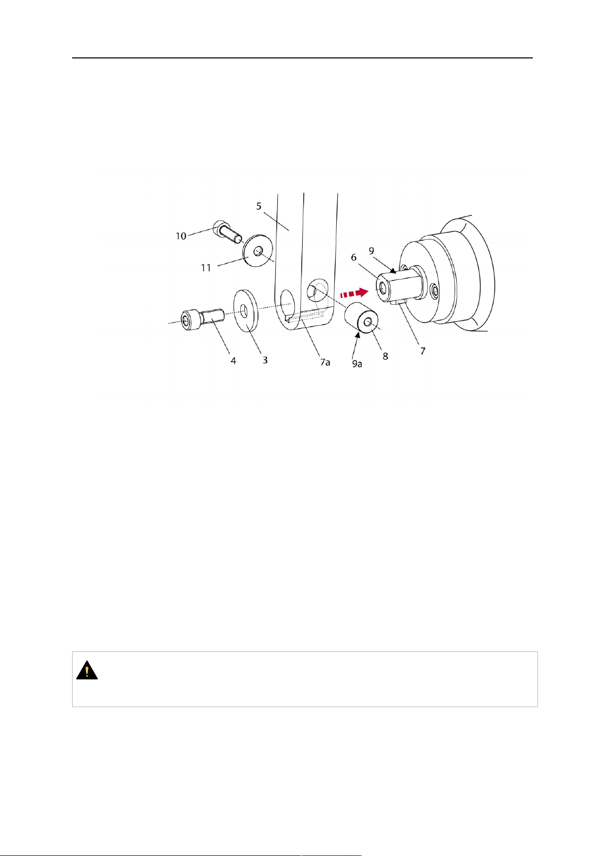
5. Place the torch mount (5) onto the journal (6) of the mounting flange, paying attention
while doing so to the exact alignment of the feather key (7) and the corresponding
groove (7a).
6. Insert the clamping mandrel (8) into the lateral hole (see illustration) and position it so
that the mating surfaces (9a) of the clamping mandrel rest on the mating surface (9) of
the journal.
0463 373 101
- 24 -
© ESAB AB 2018

5 INSTALLATION
7. Fix the clamping mandrel from the opposite side using the M6 cylinder screw with
hexagon socket (10) and the Ø22 mm washer (11).
8. Screw the axial cylinder screw (4) with the Ø9 mm washer (3) into the mounting flange
and tighten firmly.
3 - Washer Ø9 mm 8 - Clamping mandrel
4 - Axial cylinder screw with hexagon
9 - Mating surface of mounting flange
socket M8×16
5 - Torch mount 9a - Mating surfaces of clamping mandrel
6 - Mounting flange journal 10 - Cylinder screw with hexagon socket
M6×30
7 Feather key 11 - Washer Ø22×6.4 mm
7a - Groove for feather key
5.1.2 Standard arm cable assembly for KS-2 and FL-2
The cable assembly must be aligned to the intended use in length and design. The type of
cooling for the torch and the cable assembly must be the same (either gas or water cooled
respectively). In order to prevent damage to the torch system and other components, it is
imperative to observe the following instructions.
0463 373 101
- 25 -
© ESAB AB 2018
5 INSTALLATION
UZMANĪBU!
• Coordinate the length and design of the cable assembly to suit the range of
action of the robot.
• Do not bend, compress or overstretch the cable assembly.
• Fix the cable assembly such that is can be moved freely and cannot become
entangled.
• Any additional holding devices possibly installed, for example a balancer,
must not crush or bend the cable assembly.
• Extreme turning movements must be avoided in which the cable assembly
may become twisted.
• Chafing on the robot or other objects must be excluded.
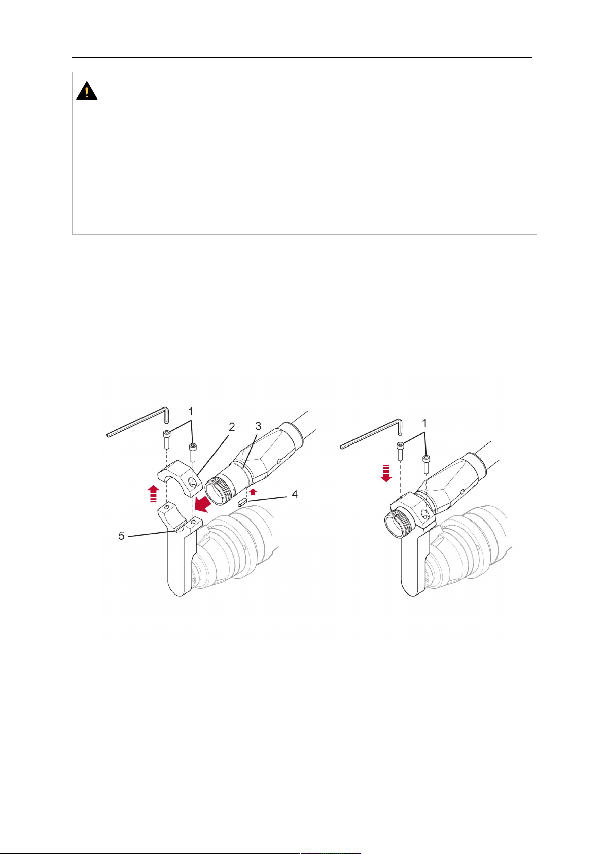
1. Unscrew the cylinder screws (1) and lift off the top section (2) of the torch mount.
2. Insert the feather key (4) into the recess of the neck support flange (3) from below.
3. Align the neck support flange (3) including the feather key (4) to the groove (5) of the
torch mount and push into the groove right up to the stop of the flange.
4. Hold the cable assembly in this position and simultaneously place the top section (2)
back onto the torch mount. First screw both cylinder screws (1) loosely in to about the
same length, then tighten alternately. The top section (2) of the mount should have an
even gap to the bottom section.
The front part of the cable assembly is directly clamped into the torch mount (see
illustration below).
1 - Cylinder screws 4 - Feather key
2 - Torch mount top section 5 - Groove for feather key
3 - Neck support flange
5.1.3 RTKS-2 wire feeder connection
In order to be able to create the connection, the cable assembly must be mounted as
described in the "Installing the cable assembly" section and equipped following "Installing the
wire guide" section. Only then can the central and media connection take place. Proceed as
described below:
0463 373 101
- 26 -
© ESAB AB 2018

5 INSTALLATION
1. Connect the central connector of the cable assembly (2) to the wire feeder cabinet
socket. Tighten the central connector sleeve nut fingertight. Do not use tools.
1 - Burndy Connector 4 - Return of heated water (red cap)
2 - EURO central connector 5 - Return of heated water (red cap)
3 - Air blow-out 6 - Main Wire feeder
2. For water cooled systems. Connect the water hoses to the cooling circuit. The end of
the hose marked blue (4) is connected to the water outlet, and the end marked red (5)
is connected to the water return.
3. Connect the blow-out line (3) to the corresponding connection of the feeder.
4. Connect the Burndy Connector to the wire feeder. (1) to the feeder. See section
"Electrical connections".
IEVĒROJIET!
All hoses and the control line must be installed so they can not bend or get
damaged!
5.1.4 RTKS-2 electrical connections
5.1.4.1 RTKS-2 safety-off mechanism connection
The switch for the safety-off functionality RTKS-2 is connected through the control cable,
see (3) in the illustration below. This connects to the RTKS-2 unit via the 4-pole plug (4) that
contains circuits for the push-button (6) and the safety-off signal (7).
If a collision is detected, the control circuit for the safety-off signal (7), which is normally
closed, will be interrupted.
Rating of the control circuit: max. 48 V / 1 A
0463 373 101
- 27 -
© ESAB AB 2018

5 INSTALLATION
2 - Burndy connector 5 - RTKS-2 connector for control cable plug
4 - Control cable plug
Burndy savienotāja tapas
A. Gāzes sprauslas
pieskāriena uztvērējs
C. Sadursmes sensors
F. 0V
G. + motora spriegums
H. - motora spriegums
D. Sadursmes sensors
E. Pakāpeniska padeve
If the robot control provides a control circuit for nozzle sense functionality, the connection is
accomplished with a 1-wire connection.
Rating of the control circuit: max 50 V / 5 A.
BĪSTAMI
If the nozzle sense function is not being used, the open end of the control cable on
the power source connection side must be properly isolated in order to avoid short
circuits. During certain problems on the torch head, the full welding potential may be
present on this cable.
UZMANĪBU!
After detection of contact (gas nozzle on work piece), quickly reduce or cut off the
maximum current in the nozzle sense circuit in order to avoid overloading of the
system.
Allowed load max. 1 minute at the rated nominal current.
5.1.5 RTKS-2 Torch installation
Continue according to section "Torch installation".
0463 373 101
- 28 -
© ESAB AB 2018
5 INSTALLATION
5.2 RTFL-2 standard arm installation
5.2.1 RTFL-2 rigid mount
1. Position the RT FL-2 (2) with the index pin on the robot arm and fix it with the hexagon
socket screw included.
The FL-2 is directly compatible with robots with tool flange according to DIN ISO
9409-1-A40 (diameter 40mm, 4×M6). If the rigid mount does not fit, use an adapter
flange (3).
IEVĒROJIET!
Ensure that the index pin is located correctly. The maximum torque of 1.2Nm
(10.5in.lb) must be observed for the fastening of the adapter flange screws.
Prevent self-loosening of the screws by using suitable thread locking
measures.
2. Install torch mount (1). Only torch mounts having a hole pattern equivalent with the
mounting surface may be attached. If necessary, carefully press the cylindrical pins (4)
into the corresponding holes in the bracket. The pins should protrude by
approximately 5mm (0.2in.). Position the torch mount on the RTFL-2 (2) and
carefully insert the cylindrical pins (4) into the holes provided. Take the position of the
torch into account. Two mounting positions may be potentially possible.
3. Screw the mount evenly using the enclosed cylinder screws with hexagon socket (5).
IEVĒROJIET!
The maximum tightening torque for the cylinder screw (5) is 6Nm (53in.lb)
and the property class category is 8.8.
0463 373 101
- 29 -
© ESAB AB 2018

5 INSTALLATION
4 - Cylindrical pins Ø4×20
5 - Cylinder screw with hexagon socket M6
DIN 912 (length of the screw depending on
the torch mount)
Side view
Torch installation with adjustable mount
Torch mounts with a central clamping assembly can only be fastened on the journal of the
mounting flange. For this, the mounting flange must be fastened first.
1. If applicable, carefully press the cylindrical pins (1) into the corresponding holes in the
mounting flange. Avoid the formation of burrs. The pins should protrude by
approximately 5 mm (0.2 in.).
2. Position the mount on the RTFL-2 and carefully insert the cylindrical pins (1) into the
holes provided. In doing so, take the later position of the torch into account. Two
mounting positions may be potentially possible.
3. Then screw down the mounting flange evenly using the enclosed cylinder screws with
hexagon socket (2).
IEVĒROJIET!
The maximum tightening torque for the cylinder screw (2) is 7.1 Nm (62.8
in.lb) and the property class category is 8.8.
4. Unscrew the axial cylinder screw with hexagon socket (4) out of the mounting flange
together with the washer (3).
1 - Cylindrical pins Ø4×14 3 - Washer Ø9 mm
2 - Cylinder screw with hexagon socket
M6×16
4 - Axial cylinder screw with hexagon
socket M8×16
5. Place the torch mount (5) onto the journal (6) of the mounting flange, paying attention
while doing so to the exact alignment of the feather key (7) and the corresponding
groove (7a).
0463 373 101
- 30 -
© ESAB AB 2018
5 INSTALLATION
6. Insert the clamping mandrel (8) into the lateral hole (see illustration) and position it so
that the mating surfaces (9a) of the clamping mandrel rest on the mating surface (9) of
the journal.
7. Fix the clamping mandrel from the opposite side using the M6 cylinder screw with
hexagon socket (10) and the Ø22 mm washer (11).
8. Screw the axial cylinder screw (4) with the Ø9 mm washer (3) into the mounting flange
and tighten firmly.
3 - Washer Ø9 mm 8 - Clamping mandrel
4 - Axial cylinder screw with hexagon
9 - Mating surface of mounting flange
socket M8×16
5 - Torch mount 9a - Mating surfaces of clamping mandrel
6 - Mounting flange journal 10 - Cylinder screw with hexagon socket
M6×30
7 - Feather key 11 - Washer Ø22×6.4 mm
7a - Groove for feather key
5.2.2 RTFL-2 torch installation
Continue according to section "Torch installation".
5.3 RTKSC-2 hollow wrist system installation
5.3.1 RTKSC-2 mount with safety off mechanism
UZMANĪBU!
For hollow wrist systems make sure that the clear space around the robot is at least
Ø45 mm (1.8 in.) around the wrist and 50 mm (2.0 in.) near the wire feeder.
0463 373 101
- 31 -
© ESAB AB 2018

5 INSTALLATION
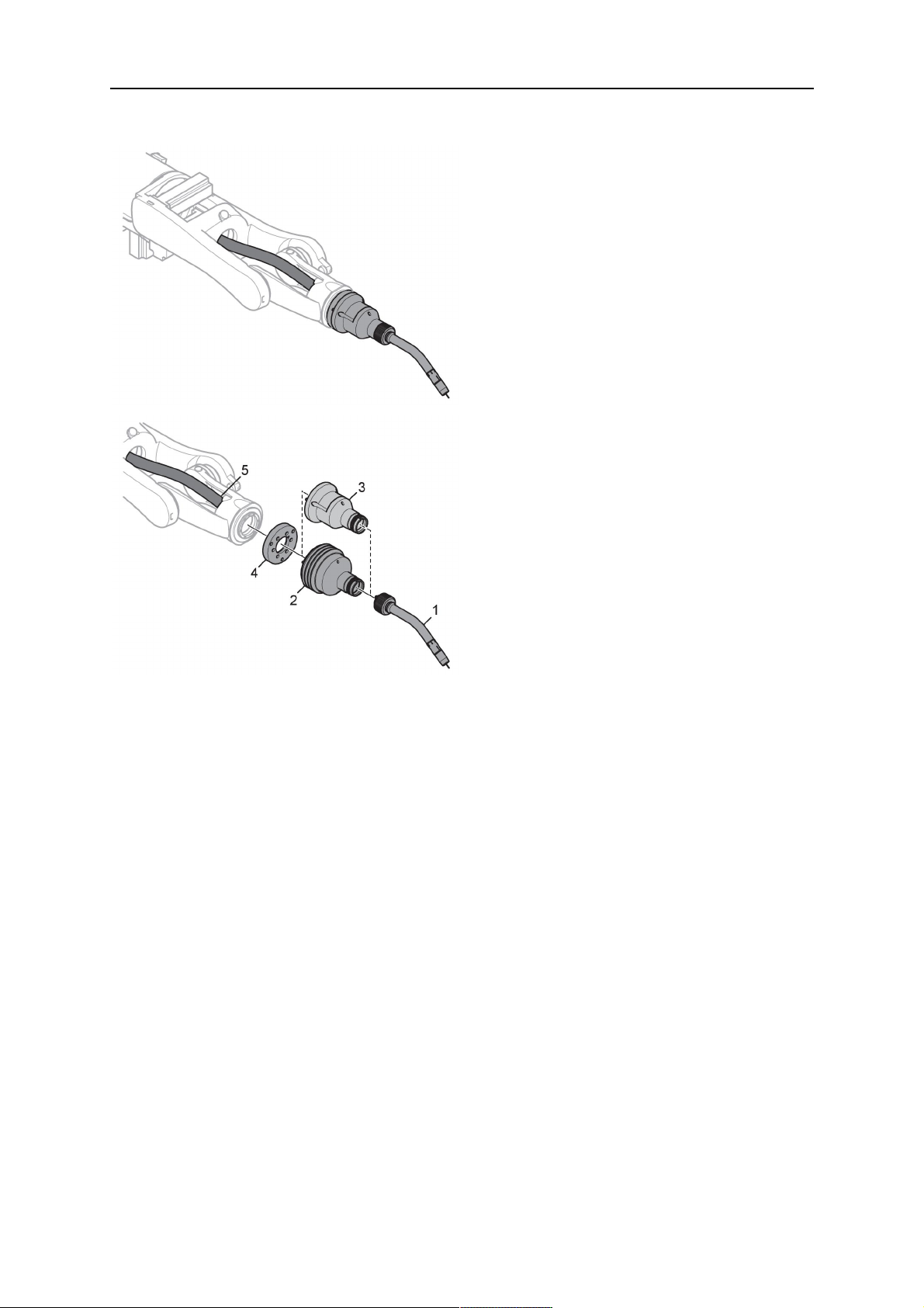
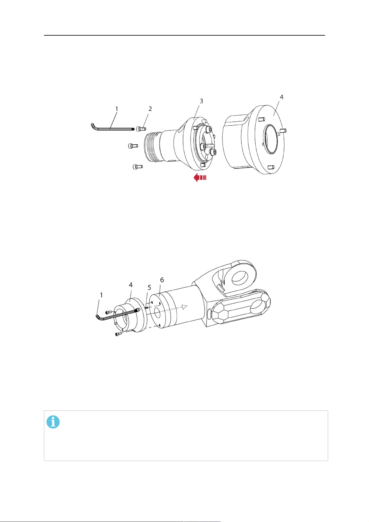
1. Remove the three screws (2) from the front cover (3) of the torch mount and carefully
pull the cover off the RTKSC-2 main body (5). Take care not to damage the micro
switches installed inside the assembly.
1 - Hexagon wrench 4 mm 4 - Rubber boot
2 - 3× M5×12 screws 5 - RT KSC-2 main body
3 - RT KSC-2 front cover
1. Pull off the rubber boot (4) from the RTKSC-2 main body (5) to the front.
2. Now position the RTKSC-2 main body (5) on the adapter flange (7) so that the index
pin is correctly seated. Attach with the screws (6) enclosed.
3. Reinstall the rubber boot (4) on the RTKSC-2 main body (5) and make sure it is
correctly located in the grooves on the front and back flange.
4. Istall the adapter flange (7) on the robot.
Fastening torque max. 2.2 Nm (19.5 in.lb).
1 - Hexagon wrench 4 mm 3 - 3× M5×12 hexagon socket screws
2 - Rubber boot 4 - Adapter flange
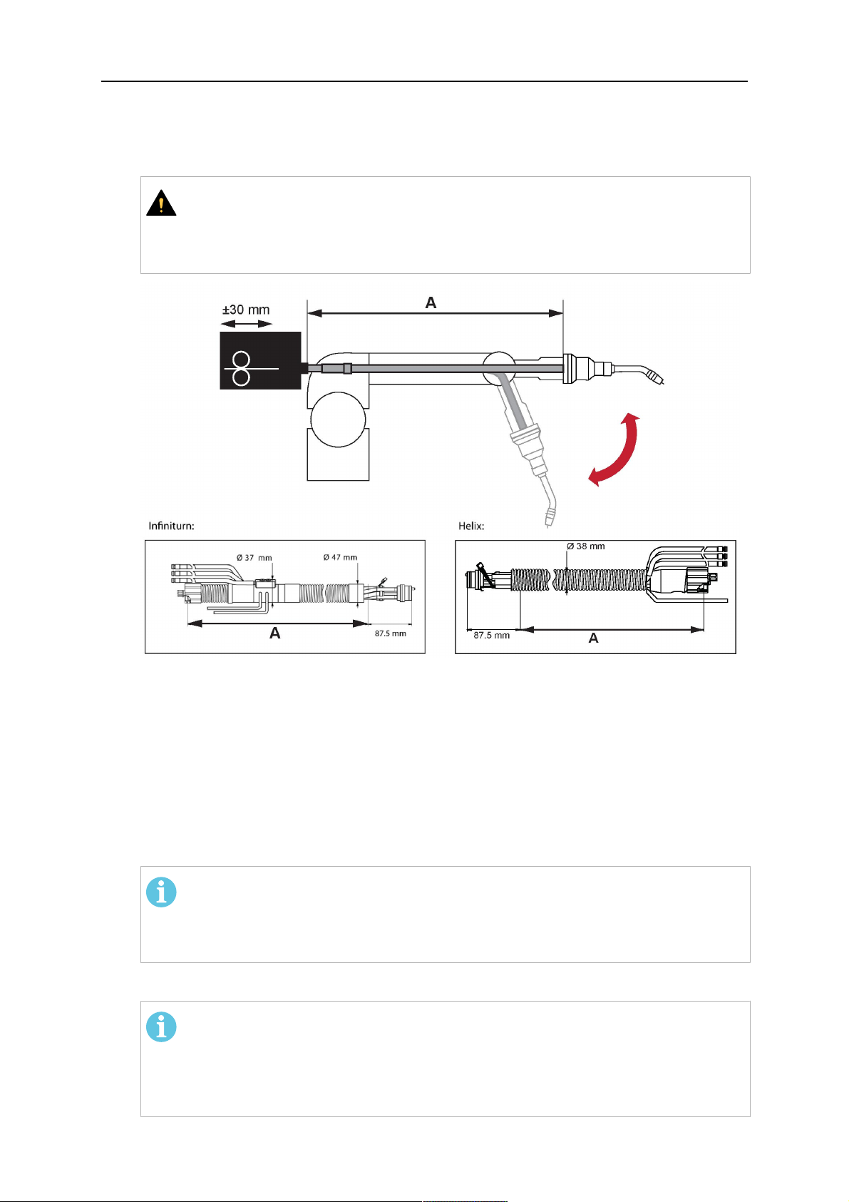
5.3.2 Mounting the cable assembly
IEVĒROJIET!
In order to adjust the wire feeder position to the cable assembly length, it must be
mounted on an adjustable support with a possible movement of ±2-3cm (±1in.) to
the back and to the front. The length of the cable assembly must be determined
from the centred mounting position of the wire feeder.
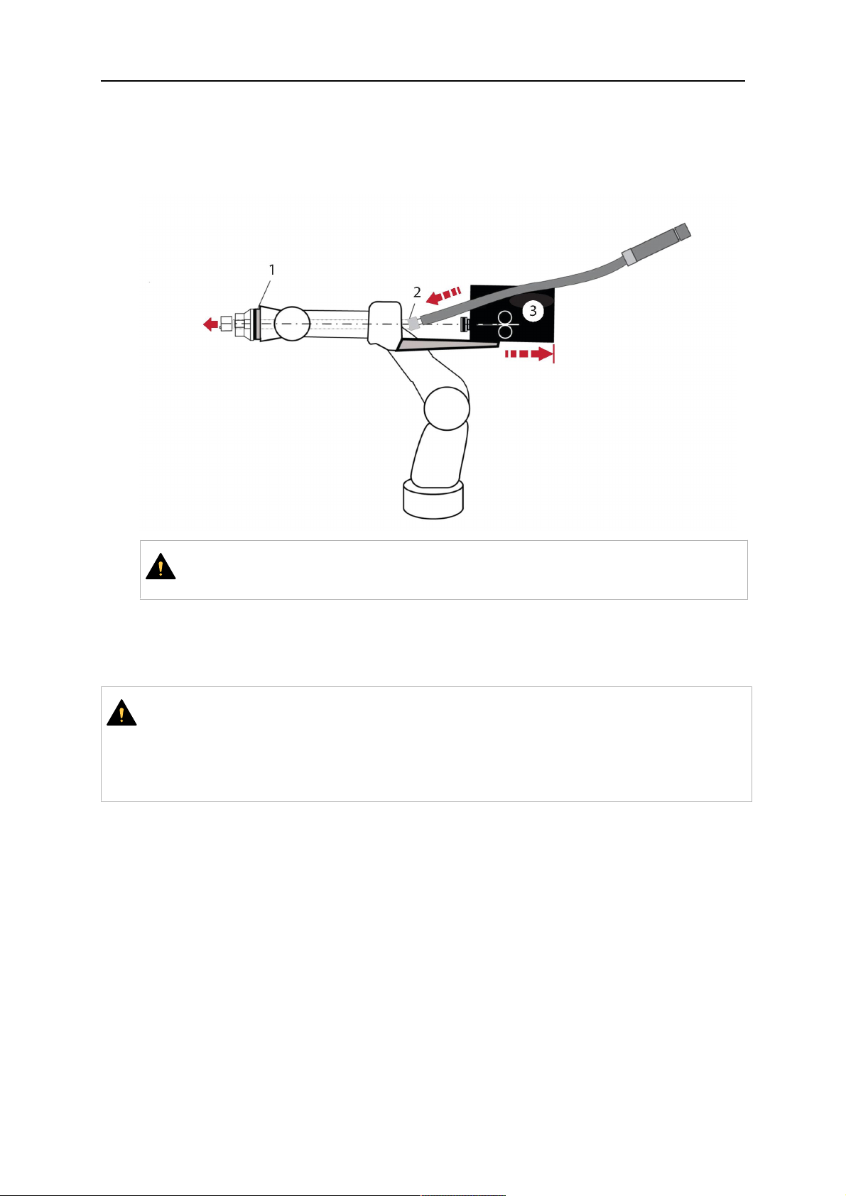
1. Move the robot arm into a completely straight position, see illustration below. Make
sure that (1) axis 6 (rotation around the torch axis) is in 0° position.
2. Move the feeder (3) completely to the back in order to create space for inserting the
cable assembly. If it is not possible to move the feeder sufficiently, it should be
removed from the robot.
0463 373 101
- 32 -
© ESAB AB 2018
5 INSTALLATION
3. Insert the cable assembly with the coupling (2) first into the robot arm and feed it
through the robot wrist.
4. The feeder should only be installed again after the correct mounting position with
respect to the cable length has been determined. (See section "Installing the cable
assembly").
UZMANĪBU!
Axis 6 must be in 0° position.
5.3.2.1 RTKSC-2 feeder cabinet connections
When installed for the first time, the position of the wire feeder cabinet must be adjusted to
the length of the cable assembly. First, the robot arm must be fully extended (straight).
UZMANĪBU!
As long as the correct position of the feeder corresponding to the length of the cable
assembly has not been determined, be careful when moving the robot arm and
avoid overstretching the cable. It is helpful to loosen the positioning screws of the
feeder before moving the robot arm to allow the feeder to follow the cable assembly.
0463 373 101
- 33 -
© ESAB AB 2018

5 INSTALLATION
1. Loosen the sliding mechanism of the wire feeder and connect the cable assembly.
2. Now adjust the position of the wire feeder to suit the length of the Infiniturn or Helix
cable, as indicated with "A" in the illustration below.
UZMANĪBU!
When adjusting the position of the feeder cabinet, make sure that the cable
assembly is not under stress when the robot arm is in stretched-out position.
It is normal for the cable assembly to sag slightly, it should never be taut.
3. Before securing the wire feeder in its permanent position, ensure that the Euro
connectors are tightly connected. Then turn the torch mount down and up again
(rotating on the axis 5), in order not to tighten the cable assembly too much against
the feeder (see illustration above). Once this is done, tighten the feeder in that
position.
4. For water cooled systems, connect the water lines to the cooling circuit. See section
"Cable assemblies for hollow wrist systems" in the TECHNICAL DATA chapter for
indications.
The hose with the blue rubber cap is for cooling water to the torch, the hose with the
red rubber cap returns the heated water. Make sure the hoses will not kink or get
otherwise blocked.
IEVĒROJIET!
A Helix cable assembly used for a gas cooled system must not be connected
to a cooling circuit. As the water connections are not needed, they may be cut
off.
5. Connect the blow-out hose (black rubber cap) to the corresponding outlet of the wire
feeder.
IEVĒROJIET!
If the blow-out function is not used, the blow-out hose must be sealed with the
rubber cap enclosed. With Infiniturn systems, the blow-out air must be
supplied to the corresponding connection hose, if it is not permitted to connect
blow-out air to the shield gas connection!
6. Install the necessary plug on the control cable and connect it to the safety off circuit
interface of the wire feeder (see section "Electrical connections").
0463 373 101
- 34 -
© ESAB AB 2018

5 INSTALLATION
5.3.3 RTKSC-2 cable assembly
The cable assembly must be aligned to the intended use in length and design. The type of
cooling for the torch and the cable assembly must be the same (either gas or water cooled
respectively). In order to prevent damage to the torch system and other components, it is
imperative to observe the following instructions.
UZMANĪBU!
• Coordinate the length and design of the cable assembly to suit the range of
action of the robot.
• Do not bend, compress or overstretch the cable assembly.
• Fix the cable assembly such that is can be moved freely and cannot become
entangled.
• Any additional holding devices possibly installed, for example a balancer,
must not crush or bend the cable assembly.
• Extreme turning movements must be avoided in which the cable assembly
may become twisted.
• Chafing on the robot or other objects must be excluded.
5.3.3.1 RTKSC-2 cable assembly installation
IEVĒROJIET!
For some robots, it may be possible to deviate from this order, and first connect the
cable assembly to the RTKSC-2, then thread the cable from the front through the
robot arm. If in doubt, follow the suggested order.
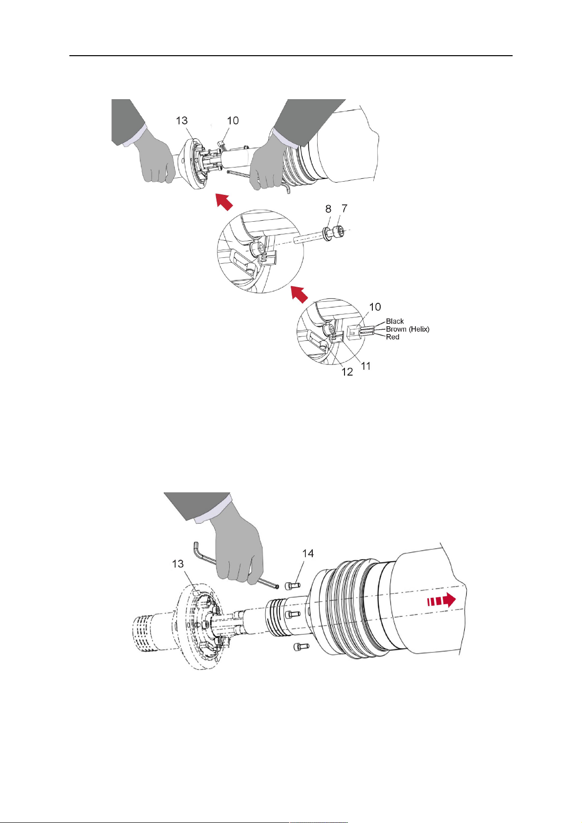
1. Loosen the three screws (7) with the associated washers and remove them from the
RTKSC-2 cover (1). See illustration below.
2. Install the supplied O-rings (4) into the grooves in the cover (1).
3. Pull the cable assembly approximately 15 cm (6 in.) from the main body (3).
0463 373 101
- 35 -
© ESAB AB 2018

5 INSTALLATION
4. Insert the coupling (2) into the socket of the cover (1) as shown. Align the index pin (6)
with the index hole (5) in the main body and insert completely.
IEVĒROJIET!
Make sure that the position of the O-rings are not shifted by the index pin
during the assembly.
1 - RTKSC-2 cover 5 - Index hole
2 - Coupling 6 - Index pin
3 - RTKSC-2 main body 7 - 3× M5×35 screws
4 - 3× O-ring for water cooled systems 11 - Control cable connector
5. Insert the three screws (7) with the associated washers (8) and tighten gently with the
enclosed hexagonal wrench, see below illustration.
Fastening torque approximately 2 Nm (18 in.lb).
0463 373 101
- 36 -
© ESAB AB 2018

5 INSTALLATION
6. If present, insert the control cable plug (10) into the connector (11) and make sure it is
firmly seated.
7 - 3× M5×35 screw 11 - Control cable connector
8 - Washer 12 - 2× Micro switch
10 - Control cable plug 13 - Index pin
7. Gently push back the cable assembly into the robot arm and carefully seat the
RTKSC-2 cover (1) in place. Observe the index pin (13) to be in the correct position.
Make sure the two micro switches (12) are not damaged if present.
8. Insert the three M5 screws (14) and tighten without excessive force.
13. Index pin
14. 3× M5×12 screws
0463 373 101
- 37 -
© ESAB AB 2018

5 INSTALLATION
5.3.3.2 RTKSC-2 electrical connections
IEVĒROJIET!
After connecting the control cable, secure the cable in order to protect it from getting
caught while the robot is moving.
Usually, the control cable will be directly connected to the wire feeder. See the
manufacturer's documentation for details. The link to the robot control is then
implemented via the power source controller.
RTKSC-2 safety-off mechanism connection
The switch for the safety-off functionality RTKSC-2 is connected through the control cable,
see (3) in the illustration below. This connects to the RTKSC-2 unit via the control cable plug
(1).
The safety-off signal requires a 2-wire connection (black/black) to the safety-off circuit in the
robot control (5).
If a collision is detected, the control circuit (normally closed) will be interrupted (4).
Rating of the control circuit: max. 48 V / 1 A.
1 - Control cable plug 3 - Burndy connector VVV
2 - EURO central connector
Burndy savienotāja tapas
A. Gāzes sprauslas
pieskāriena uztvērējs
C. Sadursmes sensors
F. 0V
G. + motora spriegums
H. - motora spriegums
D. Sadursmes sensors
E. Pakāpeniska padeve
RTKSC-2 nozzle sense function connection
If the robot control provides a control circuit for nozzle sense functionality.
The connection is accomplished with a 2-wire connection (black/black) to the nozzle sense
circuit in the robot control (5), see illustration below.
0463 373 101
- 38 -
© ESAB AB 2018

5 INSTALLATION
Usually, the control cable will be directly connected to the wire feeder. See the
manufacturer's documentation for details. The link to the robot control is then implemented
via the power source robot interface.
Rating of the control circuit: max. 50 V / 5 A.
BĪSTAMI
If the nozzle sense function is not being used, the open end of the control cable on
the power source connection side must be properly isolated in order to avoid short
circuits. During certain problems on the torch head, the full welding potential may be
present on this cable.
UZMANĪBU!
After detection of contact (gas nozzle on work piece), quickly reduce or cut off the
maximum current in the nozzle sense circuit in order to avoid overloading of the
system.
Allowed load max. 1 minute at the rated nominal current.
1 - Control cable plug 3 - Control cable
2 - EURO central connector
5.3.4 RTKSC-2 torch installation
Continue according to section "Torch installation".
0463 373 101
- 39 -
© ESAB AB 2018
5 INSTALLATION
5.4 RTFLC-2 installation
5.4.1 RTFLC-2 mount
1. Remove the three M5 screws (2) from the front cover (3) of the RT FLC-2 torch mount
and carefully pull the cover off the main body (4).
1 - Hexagon wrench 4 mm 3 - RT FLC-2 front cover
2 - 3× M5×12 screws 4 - RT FLC-2 main body
2. Now position the RT FLC-2 main body (4) on the adapter flange (6) so that the index
pin is correctly seated. Attach with the screws (5) enclosed
Fastening torque max. 2.2 Nm (19.5 in.lb).
1 - Hexagon wrench 4 mm 5 - 3× M5×12 hexagon socket screws
4 - RT FLC-2 main body 6 - Adapter flange
5.4.2 RTFLC-2 wire feeder connection
5.4.2.1 Feeding through the robot arm
IEVĒROJIET!
In order to adjust the wire feeder position to the cable assembly length, it must be
mounted on an adjustable support with a possible movement of ± 2-3 cm (± 1 in.) to
the back and to the front. The length of the cable assembly must be determined
from the centred mounting position of the wire feeder.
0463 373 101
- 40 -
© ESAB AB 2018

5 INSTALLATION
1. Move the robot arm into a completely straight position, see illustration below. Make
sure that (1) axis 6 (rotation around the torch axis) is in 0° position.
2. Move the feeder (3) completely to the back in order to create space for inserting the
cable assembly. If it is not possible to move the feeder sufficiently, it should be
removed from the robot.
3. Insert the cable assembly with the coupling (2) first into the robot arm and feed it
through the robot wrist.
4. The feeder should only be installed again after the correct mounting position with
respect to the cable length has been determined. (See section "Installing the cable
assembly").
UZMANĪBU!
Important! Axis 6 must be in 0° position.
5.4.2.2 RTFLC-2 feeder cabinet connections
When installed for the first time, the position of the wire feeder cabinet must be adjusted to
the length of the cable assembly. First, the robot arm must be fully extended (straight).
UZMANĪBU!
As long as the correct position of the feeder corresponding to the length of the cable
assembly has not been determined, be careful when moving the robot arm and
avoid overstretching the cable. It is helpful to loosen the positioning screws of the
feeder before moving the robot arm to allow the feeder to follow the cable assembly.
0463 373 101
- 41 -
© ESAB AB 2018
5 INSTALLATION
1. Loosen the sliding mechanism of the wire feeder and connect the cable assembly.
Refer to the instruction of the feeder manufacturer.
2. Now adjust the position of the wire feeder to suit the length of the Infiniturn or Helix
cable, as indicated with "A" in the illustration below.
UZMANĪBU!
When adjusting the position of the feeder cabinet, make sure that the cable
assembly is not under stress when the robot arm is in stretched-out position.
It is normal for the cable assembly to sag slightly, it should never be taut.
3. Before securing the wire feeder in its permanent position, ensure that the Euro
connections are tightly connected. Then turn the torch mount down and up again
(rotating on the axis 5), in order not to tighten the cable assembly too much against
the feeder (see illustration above). Once this is done, tighten the feeder in that
position.
4. For water cooled systems, connect the water lines to the cooling circuit. See section
"Cable assemblies for hollow wrist systems" in the TECHNICAL DATA chapter for
indications.
The hose with the blue rubber cap is for cooling water to the torch, the hose with the
red rubber cap returns the heated water. Make sure the hoses will not kink or get
otherwise blocked.
IEVĒROJIET!
A Helix cable assembly used for a gas cooled system must not be connected
to a cooling circuit. As the water connections are not needed, they may be cut
off.
5. Connect the blow-out hose (black rubber cap) to the corresponding outlet of the wire
feeder.
IEVĒROJIET!
If the blow-out function is not used, the blow-out hose must be sealed with the
rubber cap enclosed. With Infiniturn systems, the blow-out air must be
supplied to the corresponding connection hose, if it is not permitted to connect
blow-out air to the shield gas connection!
0463 373 101
- 42 -
© ESAB AB 2018

5 INSTALLATION
6. Install the necessary plug on the control cable and connect it to the safety off circuit
interface of the wire feeder (see section "Electrical connections").
5.4.3 RTFLC-2 cable assembly
The cable assembly must be aligned to the intended use in length and design. The type of
cooling for the torch and the cable assembly must be the same (either gas or water cooled
respectively). In order to prevent damage to the torch system and other components, it is
imperative to observe the following instructions.
UZMANĪBU!
• Coordinate the length and design of the cable assembly to suit the range of
action of the robot.
• Do not bend, compress or overstretch the cable assembly.
• Fix the cable assembly such that is can be moved freely and cannot become
entangled.
• Any additional holding devices possibly installed, for example a balancer,
must not crush or bend the cable assembly.
• Extreme turning movements must be avoided in which the cable assembly
may become twisted.
• Chafing on the robot or other objects must be excluded.
5.4.3.1 RTFLC-2 cable assembly installation
In a hollow wrist system the recommended order of installation is to feed the cable assembly
through the robot arm before connecting the cables to the torch mount.
When the cable assembly is correctly installed in the hollow wrist, continue the installation
according to the procedure described below.
IEVĒROJIET!
For some robots, it may be possible to deviate from this order, and first connect the
cable assembly to the RTKSC-2 and RTFLC-2, then thread the cable from the front
through the robot arm. If in doubt, follow the suggested order.
1. Loosen the three screws (7) with the associated washers and remove them from the
RTFLC-2 cover (1). See illustration below.
2. Install the supplied O-rings (4) into the grooves in the cover (1). For gas cooled
systems, only one O-ring (4a) is needed, for water cooled systems all three O-rings
are needed.
3. Pull the cable assembly approximately 15 cm (6 in.) from the main body (3).
0463 373 101
- 43 -
© ESAB AB 2018

5 INSTALLATION
4. Insert the coupling (2) into the socket of the cover (1) as shown. Align the index pin (6)
with the index hole (5) in the main body and insert completely.
IEVĒROJIET!
Take great care that the position of the O-rings is not shifted by the index pin
during the assembly.
1 - RT FLC-2 cover 5 - Index hole
2 - Coupling 6 - Index pin
3 - RT FLC-2 main body 7 - 3× M5×35 screws
4 - 3× O-ring for water cooled systems 11 - Control cable connector
5. Insert the three screws (7) with the associated washers (8) and tighten gently with the
enclosed hexagonal wrench, see below illustration.
Fastening torque approximately 2 Nm (18 in.lb).
0463 373 101
- 44 -
© ESAB AB 2018
5 INSTALLATION
6. If present insert the control cable plug (10) into the connector (11) and make sure it is
firmly seated.
7 - 3× M5×35 screw 11 - Control cable connector
8 - Washer 12 - 2× Micro switch
10 - Control cable plug 13 - Index pin
7. Gently push back the cable assembly into the robot arm and carefully seat the
RTFLC-2 cover (1) in place. Observe the index pin (13) to be in the correct position.
Make sure the two micro switches (12) are not damaged if present.
8. Insert the three M5 screws (14) and tighten without excessive force.
13 - Index pin 14 - 3x M5x12 screws
0463 373 101
- 45 -
© ESAB AB 2018
5 INSTALLATION
5.4.4 RTFLC-2 electrical connections
IEVĒROJIET!
After connecting the control cable, secure the cable in order to protect it from getting
caught while the robot is moving.
Usually, the control cable will be directly connected to the wire feeder. See the
documentation of the manufacturer for details. The link to the robot control is then
implemented via the power source controller.
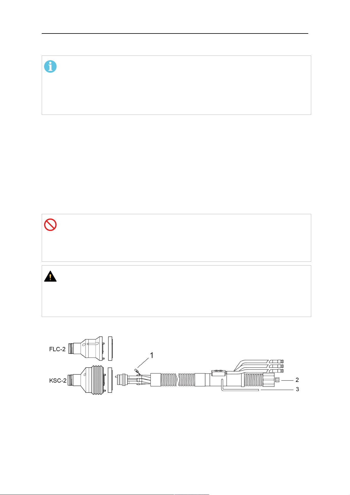
5.4.4.1 RTFLC-2 hollow wrist system with Infiniturn cable assembly
Connecting the nozzle sense function
If the robot control provides a control circuit for nozzle sense functionality.
The connection is accomplished with a 2-wire connection (black/black) to the nozzle sense
circuit in the robot control (5), see illustration below.
Usually, the control cable will be directly connected to the wire feeder. See the
manufacturer's documentation for details. The link to the robot control is then implemented
via the power source robot interface.
Rating of the control circuit: max. 50 V / 5 A.
BĪSTAMI
If the nozzle sense function is not being used, the open end of the control cable on
the power source connection side must be properly isolated in order to avoid short
circuits. During certain problems on the torch head, the full welding potential may be
present on this cable.
UZMANĪBU!
After detection of contact (gas nozzle on work piece), quickly reduce or cut off the
maximum current in the nozzle sense circuit in order to avoid overloading of the
system.
Allowed load max. 1 minute at the rated nominal current.
1 - Control cable plug 3 - Control cable
2 - EURO central connector
0463 373 101
- 46 -
© ESAB AB 2018
5 INSTALLATION
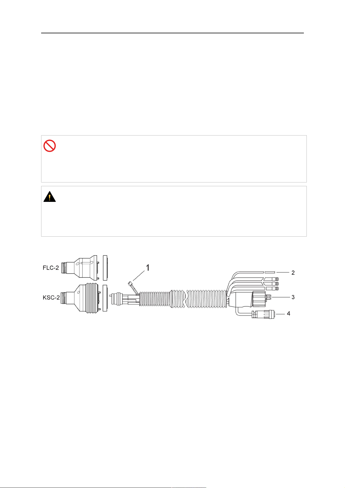
5.4.4.2 RTFLC-2 hollow wrist system with Helix cable assembly
Connecting the nozzle sense function
If the robot control provides a control circuit for nozzle sense functionality.
The connection is accomplished with a 1-wire connection (green) to the nozzle sense circuit
in the robot control (5), see illustration below.
Usually, the control cable will be directly connected to the wire feeder. See the
manufacturer's documentation for details. The link to the robot control is then implemented
via the power source robot interface.
Rating of the control circuit: max. 50 V / 5 A.
BĪSTAMI
If the nozzle sense function is not being used, the open end of the control cable on
the power source connection side must be properly isolated in order to avoid short
circuits. During certain problems on the torch head, the full welding potential may be
present on this cable.
UZMANĪBU!
After detection of contact (gas nozzle on work piece), quickly reduce or cut off the
maximum current in the nozzle sense circuit in order to avoid overloading of the
system.
Allowed load max. 1 minute at the rated nominal current.
1 - Control cable plug 3 - EURO central connector
2 - Control cable 4 - Burndy connector
5.5 Torch installation
Be sure to use the correct version of the torch mount and cable assembly (water or gas
cooled).
5.5.1 Torch neck equipment
The torch neck, see (1) in the illustration below, must always be equipped to suit the wire
diameter and material.
0463 373 101
- 47 -
© ESAB AB 2018

5 INSTALLATION
1. Select the correct wire guide, contact tip (4), tip holder (2), gas nozzle (5), and gas
diffuser/spatter protection (3). You will find an exact overview and possible alternative
equipment elements for various torch models in the spare parts list. Only use original
ESAB parts; only then is the fitting accuracy ensured.
2. Firmly tighten the tip holder and the contact tip using a suitable tool for example the
enclosed monkey wrench.
3. When using a split wire guide, remove the installed guide nipple including the o-ring
from the torch flange upon delivery if necessary (see section "Installing the neck
liner").
UZMANĪBU!
The torch must be completely equipped before welding, especially the gas
diffuser and/or spatter protection and all necessary insulators have to be
installed according to the spare parts list. Welding without these items may
cause immediate destruction of the torch.
1 - Torch neck 4 - Contact tip
2 - Tip holder 5 - Contact tip
3 - Gas diffuser
5.5.2 Aristo RT torch neck installation
IEVĒROJIET!
Check the O-rings on the flange of the torch neck before mounting. Replace the
O-rings if damaged or lost. Missing or faulty O-rings will lead to leaks of shielding
gas and coolant.
1. For hollow wrist systems, insert the torch into the torch mount in the correct
orientation, so that the locator pin fits into the slot of the RTKSC-2 or RTFLC-2
interface, see (A) in the illustration below. For standard systems, attach the torch to
the RT flange of the cable assembly, (B) in the illustration below.
Installation is only possible in the correct orientation.
2. Tighten the locking nut of the torch neck.
IEVĒROJIET!
Only tighten by hand, never use tools or excessive force.
0463 373 101
- 48 -
© ESAB AB 2018

5 INSTALLATION
3. The correct seating of the torch can be checked by means of the window (1). If the
torch has been correctly mounted, no gap should be seen through the window (1).
5.6 Installing the wire guide for standard and hollow Wrist arm
Installing the wire guide
Choose the wire guide or liner depending on the filler wire material and diameter to be used,
see the spare parts list. Accurate performance of the system can only be guaranteed when
using original ESAB wire guides.
The recommended wire guide is the split wire guide, which consists of the neck liner and a
separate guide in the cable assembly. The front part of the wire guide, which is most
stressed, can be exchanged easily and independently of the cable assembly wire guide.
For correct installation, the following steps must be followed (example for Euro central
connector).
5.6.1 Installing the neck liner
The neck liner must be selected to fit the material and diameter of the welding wire, see the
spare parts list.
0463 373 101
- 49 -
© ESAB AB 2018

5 INSTALLATION
1. If present, remove the central guide nipple (1), from the torch neck using a hexagon
wrench (size 6 mm) or a large flat-blade screwdriver.
IEVĒROJIET!
The guide nipple (1) can only be used with one-piece liners and must not be
used with the standard RT or hollow wrist system.
2. When replacing the neck liner:
Unfasten the sleeve nut and remove the torch neck.
Unfasten the liner nipple using a hexagon wrench (size 6 mm) and remove nipple and
liner from the torch neck.
3. Remove the gas nozzle and the contact tip.
4. Insert the new neck liner (2) into the torch. Carefully tighten the guide nipple using a
suitable tool, e.g. a hex-wrench (size 6 mm) or a large flat-blade screwdriver.
5. Cut the neck liner flush with the tip holder and remove the neck liner from the torch.
6. Install the contact tip.
7. Insert the neck liner again. It will be stopped by the contact tip. Measure the excess
liner sticking out of the neck.
8. Remove the liner again and shorten the front end by the measured length. Carefully
deburr the edge and make sure that the inner hole is not blocked.
9. Reinstall the neck liner and tighten the guide nipple in the neck.
5.6.2 Installing a split wire guide in the cable assembly
The correct liner must be inserted to suit the filler material and the wire diameter, see the
spare parts list.
The wire guide is inserted through the cable assembly from the rear, reaching the guide
nipple that is installed in the flange where the torch neck will be attached. The following
worksteps must be followed in order to correctly determine the wire guide length. (Example
for Euro central connector).
0463 373 101
- 50 -
© ESAB AB 2018

5 INSTALLATION
1. For standard RT system: Install the guide nipple (1) in the center hole of the neck
support flange, see illustration A below.
For hollow wrist system: Install the guide nipple (1) into the torch interface of the
RTKSC-2 / RTFLC-2 cover, see illustration B below.
2. Remove the sleeve nut (2) from the central connector, and remove the old wire guide.
3. Insert the wire guide through the central connection and push forwards as far as it will
go into the guide nipple (1), applying light pressure.
UZMANĪBU!
Ensure that the wire guide has advanced right up to the stop at the front,
rotating and pushing forward gently.
4. Measure the excess length that needs to be cut from the wire guide.
5. Remove the wire guide again and shorten the front end by the measured length.
Steel liner: grind down the burred edges if needed.
Plastic liner: make a clean cut and chamfer the edges (e.g. with a pencil sharpener)
IEVĒROJIET!
Make sure the inner opening of the liner is not obstructed by the cut wire end.
0463 373 101
- 51 -
© ESAB AB 2018
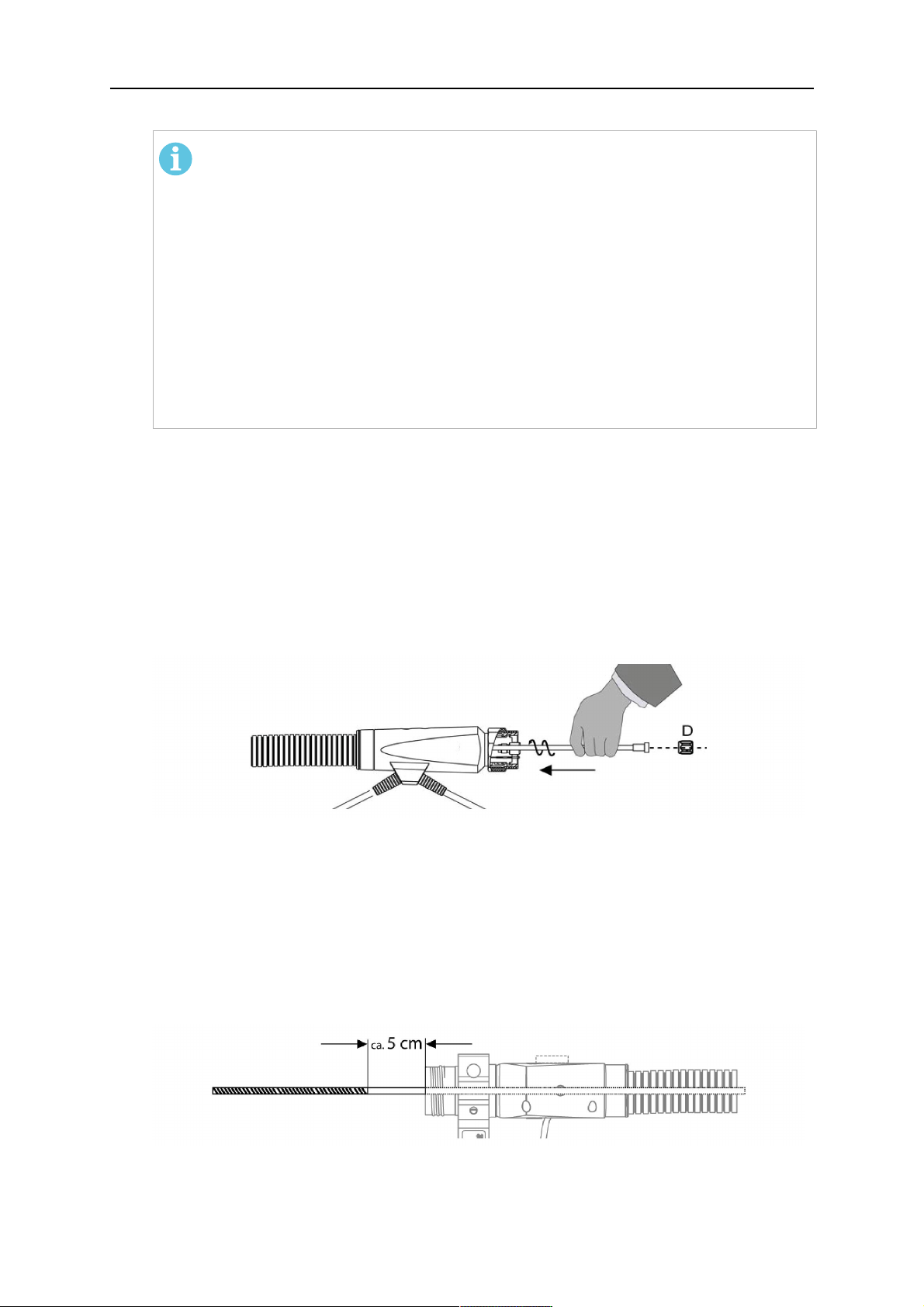
5 INSTALLATION
6. Reinstall the wire guide and attach the sleeve nut (2).
IEVĒROJIET!
For hollow wrist systems where Infiniturn and Helix cable assemblies are
used, wire guides should be installed without tension so that the ends of the
liners may rotate freely.
Important note when using a plastic liner:
The wire channel between the drive rolls of the feeder and the central
connector of the torch must be fitted with a plastic liner. Depending on the
design of the feeder, a piece of plastic liner inserted into a brass guide tube
can be used.
During wire run-in, make sure that the wire is fed correctly into the plastic liner
of the torch. If necessary, remove the cable assembly from the feeder and
insert the wire, then reattach.
5.6.3 Installing a continuous wire guide in the cable assembly
Installing a steel liner
The wire guide is inserted through the cable assembly from the rear and reaches to the
contact tip. The following worksteps must be followed for the correct calculation of the length
(example for Euro central connector):
1. Install the torch (see section "Torch neck equipment").
2. Remove the gas nozzle and contact tip from the torch.
3. Remove the sleeve nut (D) from the Euro connector.
4. Push in the liner through the central connector and fix with the sleeve nut.
5. Cut off the liner flush with the nozzle holder. To determine the thread projection of the
contact tip, pull the liner backwards and screw in the contact tip.
6. Push the liner forwards as far as it will go to the contact tip applying light pressure on
the liner and measure the length to be shortened at the rear.
7. Now remove the liner again and cut the excess length measured off it’s front end. If
needed, grind down the burred edges. Make sure the inner opening of the liner is not
obstructed by the cut wire end.
8. The insulation of the liner must be removed after cutting off in the front area, such that
the insulation protrudes out of the RM2 flange by approx. 5 cm. For this, briefly
remove the torch neck.
9. Push the liner back in again and fix with the sleeve nut (D), see above. Re-install the
gas nozzle.
0463 373 101
- 52 -
© ESAB AB 2018

5 INSTALLATION
Installing a plastic liner
1. Mount the torch neck (see section "Torch neck equipment") and equip it with a gas
nozzle and contact tip.
2. Remove the sleeve nut (D) from the Euro connector.
3. Cleanly cut off the liner, slightly break the outer edges, point slightly (e.g. with a pencil
sharpener).
4. Insert the liner through the central connector into the cable assembly with fitted torch.
If it gets stuck, rotate the liner to free it and facilitate installation.
IEVĒROJIET!
Make sure the liner is completely inserted by rotating it and slightly pushing it
forward, until you can feel it has reached its stop.
5. Mount the nipple (B) and the O-Ring (C), move it to the right position and fix it with the
sleeve nut (D) of the Euro central connector.
6. Measure the required overlap needed inside the wire feeder cabinet and cut the liner
accordingly.
5.7 Adjust the narrow gap contact tip
The adjusting tool RT42-NG is designed for the narrow gap torch necks RT42W-NG,
RT42G-NG and RT 82W-0°NG, torches with curved narrow gap contact tip. It facilitates the
precisely repeatable and fast changing of the curved contact tip.
IEVĒROJIET!
The adjusting tool must be securely fastened to a stable base, in order to prevent
the position of the device in relation to the robot cannot change unintentionally. If the
exact orientation of the device is lost, the alignment of the contact tip used for the
elaboration of the welding programs can no longer be reproduced with precision.
Select a position within the operating range of the robot for orientation (alignment) of the
contact tip to the torch. Fasten the adjusting tool firmly to a base using the fastening grooves
provided for this purpose. Fastening material is not included with the adjusting tool. Select
fastening material (screws) to suit the existing conditions.
Save all motion sequences and stop positions required to change or align the wearing parts
to a separate robot program.
Before programming the welding tasks: plan at which orientation the contact tip is to stand in
relation to the torch. The torch must then be positioned in the desired rotational position and
the contact tip aligned using the adjusting device. Only then may the welding task be
programmed. If different orientations of the contact tip are required for various welding tasks,
the contact tip has to be aligned to the new position when the welding task is changed.
BRĪDINĀJUMS!
The gas nozzle and the torch head become very hot during welding. Always allow
the torch to cool down before replacing wearing parts or adjusting the contact tip.
0463 373 101
- 53 -
© ESAB AB 2018

5 INSTALLATION
Adjust the contact tip
Move the robot torch to a position parallel to
the opening of the adjusting tool (2). Maintain
a sufficient distance to the work table to be
able to comfortably remove the gas nozzle.
Define this position in your robot program as
the wearing parts change position (stop
position 1).
Remove the gas nozzle by pulling it
downwards. Remove the welding wire in the
contact tip if necessary.
Loosen the counter nut (4) of the contact tip
while counter-holding the nozzle holder at the
wrench flat (3).
Unscrew the contact tip including the counter
nut from the nozzle holder and replace the
nozzle holder if necessary.
Completely screw the counter nut (4) onto the
new contact tip. Screw the contact tip
including the counter nut into the nozzle
holder.
Align the contact tip until it is parallel to the
opening of the adjusting tool. If necessary,
slightly unscrew the contact tip so that it can
be easily turned in both directions.
0463 373 101
- 54 -
© ESAB AB 2018
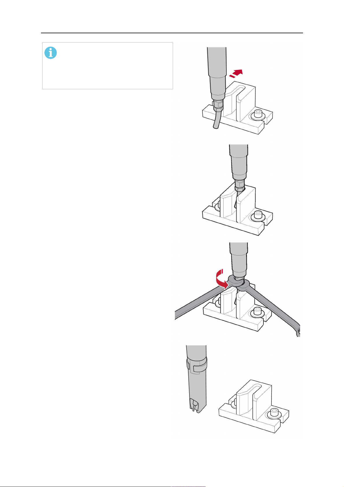
5 INSTALLATION
IEVĒROJIET!
The contact tip must be able to be
easily moved by hand in both
directions in order to enable the
threading of the adjusting tool.
Place the robot torch or contact tip directly in
front of the opening of the adjusting tool (2)
(stop position 2).
Insert it slowly from the front until it is
completely inserted into the device (stop
position 3).
The contact tip was aligned exactly in the
device during insertion. Now cautiously
tighten the counter nut (4) in this position,
while counter holding the nozzle holder at the
wrench flat.
Slowly move the robot torch out of the
adjusting gauge, return to stop position 1 and
push on the gas nozzle as far as it will go.
Allow the welding wire to run into the contact
tip and bring the robot arm into welding
position.
0463 373 101
- 55 -
© ESAB AB 2018
6 OPERATION
6 OPERATION
UZMANĪBU!
Before starting the system, check the whole installation according to the
manufacturer's instructions and applicable safety regulations.
Check the following to make sure that the system has been installed correctly:
1. Are all parts securely attached (torch, torch mount, flanges, safety-off device, cable
assembly, and wire feeder cabinet)?
2. Are all media hoses connected correctly and protected from damage?
3. Is the EURO central connector or direct connector fastened tightly?
4. Is the cable assembly length correct and suitable for the installation and can the cable
rotate freely? The cable must not be bent sharply. Any risk of the cable getting caught
on another object must be eliminated.
5. Is the control cable of the safety-off circuit connected and functioning? Move torch by
hand to test (RTKSC-2 and RTKS-2 only).
6. Is the torch firmly attached and is it completely equipped?
7. Is the wire guide installed according to the manual?
8. Are all lines and tubes arranged so that they cannot be damaged or bent?
The wire run-in can now be started, either via the wire run-in pushbutton or via the wire run-in
at the feeder.
6.1 Important information for programming (hollow wrist system only)
Fast rotation of axis 6 of the robot will significantly stress the cable assembly. In certain
cases, this can lead to damage or destruction of the cable. In order to maximize the lifetime
of the cable, we strongly suggest respecting the following limitations when programming the
robot.
Position of axis 5 Max. rotational speed of axis 6
0 – 60° 100 % (no limitations)
60° – 80° 300°/sec (approximately 50 % of max. robot speed)
> 80° 120°/sec (approximately 20 % of max. robot speed)
IEVĒROJIET!
The above values are only indications. For information on the exact rotational speed
limits, refer to the individual robot manual or contact the robot supplier.
To reposition the torch quickly, the robot arm may have to be slightly extended first to achieve
a bending angle of max. 60° of axis 5. In this position, the maximum available rotation speed
of axis 6 can be used.
When using the ESAB Helix cable assembly, the max. rotation of ±270° from the neutral
position must not be exceeded.
0463 373 101
- 56 -
© ESAB AB 2018

6 OPERATION
UZMANĪBU!
While axis 5 is bent more than 60°, the rotational speed of the torch around axis 6
must be limited, see table above.
Otherwise, the cable assembly may be damaged.
0463 373 101
- 57 -
© ESAB AB 2018

7 SERVISS UN APKOPE
7 SERVISS UN APKOPE
BRĪDINĀJUMS!
Pirms sistēmas apkopes veikšanas jāatslēdz iekārtas barošana no elektrotīkla.
Ievērojiet drošības noteikumus, kas sniegti šīs rokasgrāmatas sākumā.
Nedrīkst lietot bojātus degļus vai kabeļa blokus! Pirms iekārtas nākamās lietošanas
kvalificētam personālam jānovērš zināmie bojājumi.
BRĪDINĀJUMS!
Apdeguma traumu risks! Gāzes sprausla un degļa galva metināšanas laikā ļoti stipri
sakarst. Pirms apkopes darbiem ļaujiet deglim atdzist.
BRĪDINĀJUMS!
Lai nepieļautu traumas cilvēkiem vai iekārtas bojājumus, ievērojiet tālāk sniegtos
norādījumus.
1. RTKSC-2 vai RTFLC-2 degļa stiprinājuma, RTKS-2 aizsargizslēgšanas
mehānisma, kabeļa bloka vai Infiniturn darba līdzekļu padeves
savienojuma remontu drīkst veikt tikai ESAB servisa dienests.
2. Infiniturn darba līdzekļu padeves savienojumu nekad nedrīkst atvērt. Tajā
neatrodas detaļas, kuru apkope jāveic lietotājam, un demontāžas gadījumā
tas tiks sabojāts.
3. Nekad neizjauciet RTKSC-2 vai RTKS-2. Tas ir ar atsperi aprīkots
mehānisms. Neatbilstoša rīkošanās var radīt smagas traumas.
7.1 Obligātās pārbaudes un darbības
Pirms katras lietošanas
• Pārbaudiet degli, metināšanas uzgali, gāzes sprauslu, kakla čaulu, kabeļus un visu
aprīkojumu, vai nav vispārēju bojājumu.
IEVĒROJIET!
Lai iespējami samazinātu dīkstāves laiku, ir ieteicams pārmaiņus izmantot divus
degļa kaklus un vienmēr turēt gatavībā lietošanai aprīkotu degļa kaklu.
Ik pēc 8lietošanas stundām (atkarībā no lietojuma)
• Nomainiet metināšanas uzgali.
Katru dienu
• Manuāli pārbaudiet aizsargizslēgšanas mehānisma darbību.
• Vizuāli pārbaudiet, vai nav bojājumu, piemēram, liekumu vai plaisu.
• Pārbaudiet, vai stieples padeves ierīce ir pareizā pozīcijā. Kabeļu bloks nedrīkst būt
pārmērīgi nospriegots vai pārāk vaļīgs.
• Pārbaudiet, vai darba līdzekļu padeves savienojumos un Infiniturn darba līdzekļu
padeves savienojumā nav noplūdes.
• Veiciet degļa tīrīšanu un apkopi atbilstoši norādījumiem degļa lietošanas rokasgrāmatā.
Ik pēc 40lietošanas stundām (atkarībā no lietojuma)
• Nomainiet stieples čaulas.
• Nomainiet kakla čaulas.
Reizi nedēļā vai pēc nepieciešamības atkarībā no lietojuma
0463 373 101
- 58 -
© ESAB AB 2018

7 SERVISS UN APKOPE
• Izņemiet stieples vadotni un pārbaudiet, vai nav nodiluma un uzkrājušos netīrumu. Ja
nepieciešams, nomainiet to.
Reizi mēnesī vai pēc intensīvas lietošanas (t.i., vairāk nekā 8stundas dienā) biežāk
• Izpūtiet stieples vadotnes kanālu ar saspiestu gaisu (izņemiet metināšanas uzgali un
stieples vadotni).
• Pārliecinieties, ka visas skrūves ir cieši pievilktas.
• Pārbaudiet visus savienojumus un šļūtenes, vai nav bojājumu.
• Nomainiet pēc katriem 250kg metinātās stieples.
Pirms sistēmas drošas darbināšanas elektriskās izolācijas bojājumi jānovērš apmācītam
personālam.
0463 373 101
- 59 -
© ESAB AB 2018
8 TRAUCĒJUMMEKLĒŠANA
8 TRAUCĒJUMMEKLĒŠANA
Kļūme Iespējamais cēlonis Darbība
Stieple netiek
padota
Deglis kļūst
pārāk karsts
Metināšanas stieple pirms
ievadīšanas kabeļa blokā nav
iztaisnota
Deglis un kabeļa bloks nav pareizi
aprīkots atbilstoši stieples
diametram un stieples materiālam
Stieples vadotne nav pareizi
ievietota kabeļa blokā
Metināšanas uzgalis ir nosprostots
ar stieples gružiem
Stieples vadotne ir nodilusi
Stieples padevi traucē deglī
uzkrājušies netīrumi un gruži
Nav pareizi pievilkts metināšanas
uzgalis vai uzgaļa turētājs
Ja nepieciešams, izvelciet
metināšanas stiepli, nogrieziet un
nolīdziniet galu un iztaisnojiet
stieples pirmos 10cm. Pēc tam
ievadiet atpakaļ kabeļa blokā.
Pārbaudiet stieples vadotni (kabeļa
bloku un degļa kaklu) un
metināšanas uzgali.
Nedaudz izvelciet stieples vadotni
no Euro savienotāja. Ievietojot
stieples vadotni, ir jābūt jūtamam,
kā pēdējie centimetri ieslīd degļa
savienojuma vadotnes nipelī.
Pretējā gadījumā stieples vadotne
var būt par īsu un nepilnīgi ievietota.
Nomainiet metināšanas uzgali
un/vai stieples vadotni, izpūtiet
degļa kaklu, stieples vadotnes
kanālu un stieples vadotni ar
saspiestu gaisu.
Izmantojiet piemērotu instrumentu,
lai pievilktu tik cieši, cik var pievilkt
ar roku.
Problēmas ar
stieples padevi
Dzesēšanas sistēma darbojas
nepareizi
Dzesēšanas sistēma nav pareizi
pievienota
Pārbaudiet ūdens plūsmu, uzpildes
līmeni un tīrību.
Pārbaudiet savienojumus (ūdens
ieplūde un atplūde).
Deglis ir pārslogots Ievērojiet tehniskos datus; ja
nepieciešams, izvēlieties citu tipu.
Kabeļa blokā ir defekts Pārbaudiet kabeļus, caurules un
savienojumus.
Metināšanas uzgalis ir nolietots Nomainiet metināšanas uzgali.
Čaula ir nodilusi/netīra Pārbaudiet čaulu; izpūtiet. Ja
nepieciešams, nomainiet to.
Izmantotās dilstošās daļas nav
Pārbaudiet rezerves daļu sarakstu.
piemērotas stieples diametram vai
materiālam
Stieples padeve nav pareizi
uzstādīta
Pārbaudiet stieples padeves
rullīšus, saskares spiedienu un
spoles bremzi.
Kabeļa bloks ir saliekts vai izvietots
nelielā rādiusā
Pārbaudiet, vai kabeļa blokam nav
bojājumu. Vai čaulu var viegli
ievietot? Uzstādiet atbilstoši
norādījumiem. Skatiet sadaļu
"Kabeļa bloka uzstādīšana".
0463 373 101
Stieple ir piesārņota Izmantojiet tīrīšanas filcu.
- 60 -
© ESAB AB 2018

8 TRAUCĒJUMMEKLĒŠANA
Kļūme Iespējamais cēlonis Darbība
Stieples padeve
apstājas
metināšanas
laikā
Metināšanas
process tiek
apturēts
Poras
metināšanas
šuvē
Stieples spole ir tukša Pārbaudiet metināšanas stieples
daudzumu uz spoles stieples
padeves ierīcē.
Stieple tiek bloķēta kabeļa blokā Pārbaudiet stieples padevi
(iespējams, pārāk ātra), pārbaudiet,
vai metināšanas uzgalī nav
piesārņojuma/aizsprostojuma, ja
nepieciešams, nomainiet
metināšanas uzgali.
Stieples atkārtota aizdegšanās
Nomainiet metināšanas uzgali.
metināšanas uzgalī vai nolietots
metināšanas uzgalis
Ir nostrādājis aizsargizslēgšanas
mehānisms.
Atrodiet sadursmes vietas un
novērsiet sadursmi. Pārbaudiet, vai
vadības līnijā nav vaļīgu kontaktu.
Gāzes virpulis, ko izraisījušas
pielīpošas šļakatas
Notīriet degļa galvu; izmantojiet
gāzes difuzoru/aizsargu pret
šļakstiem
Deglī ir pārāk maza vai ārkārtīgi
liela gāzes plūsma
Pārbaudiet plūsmas ātrumu,
izmantojot mērinstrumentu.
Gāzes padevē ir defekts Pārbaudiet plūsmas ātrumu un
iespējamu noplūdi.
Stieple vai apstrādājamais
priekšmets ir mitrs vai piesārņots
Pārbaudiet stiepli un sagatavi;
izmantojiet mazāku pretšļakstu
līdzekļa daudzumu vai citu līdzekli.
Loks nav stabils Metināšanas uzgalis ir nolietots Nomainiet metināšanas uzgali.
Nepareizi metināšanas parametri Pārbaudiet metināšanas aprīkojuma
iestatījumus.
Nepietiekami elektriskie savienojumi
ķēdē
Pārbaudiet visus elektriskos
savienojumus (ieskaitot zemējuma
kabeli) starp degļa barošanas avotu
vai sagatavi, vai tie ir stingri.
0463 373 101
- 61 -
© ESAB AB 2018

9 REZERVES DAĻU PASŪTĪŠANA
9 REZERVES DAĻU PASŪTĪŠANA
UZMANĪBU!
Remontu un ar elektrību saistīto darbu drīkst veikt pilnvarots ESAB apkopes
darbinieks. Izmantojiet tikai ESAB oriģinālās rezerves daļas un dilstošās daļas.
ESAB RT degļi RTKS-2, RTFL-2, RT-KSC-2, RT-FLC-2, RT42, RT52, RT62, RT72,
RT82, RT42-NG un RT82WNG ir izstrādāti un pārbaudīti atbilstoši starptautiskajiem un
Eiropas standartiem IEC/EN 60974-7. Servisa centram, kas veicis apkopi vai remontu, ir
jānodrošina, lai izstrādājums joprojām atbilstu minētajam standartam.
Rezerves daļas un dilstošās daļas var pasūtīt no tuvākā ESAB preču izplatītāja; skatiet vietni
esab.com. Pasūtot rezerves daļu, norādiet produkta tipu, sērijas numuru, paredzēto lietojumu
un rezerves daļas numuru saskaņā ar rezerves daļu sarakstu. Tas atvieglos piegādi un
nodrošinās pareizu piegādi.
0463 373 101
- 62 -
© ESAB AB 2018

9 REZERVES DAĻU PASŪTĪŠANA
0463 373 101
- 63 -
© ESAB AB 2018

ESAB AB, Lindholmsallén 9, Box 8004, 402 77 Gothenburg, Sweden, Phone +46 (0) 31 50 90 00
http://manuals.esab.com
For contact information visit esab.com
 Loading...