


RT Robo Welding Torch System
RTKS-2, RTFL-2, KSC-2, FLC-2, RT42, RT52,
RT62, RT72, RT82, RT42-NG, RT82WNG
Betriebsanleitung
0463 373 101 DE 20181227

INHALT
1
SICHERHEIT................................................................................................ 5
1.1 Bedeutung der Symbole ........................................................................ 5
1.2 Sicherheitsvorkehrungen ...................................................................... 5
2
GARANTIE................................................................................................... 9
2.1 Bedingungen für den beabsichtigten Verwendungszweck................ 9
3
EINFÜHRUNG ............................................................................................. 11
3.1 Übersicht über Schweißbrennersysteme............................................. 12
4
TECHNISCHE DATEN................................................................................. 14
4.1 Schweißbrennerhals .............................................................................. 14
4.2 Nennspannung ....................................................................................... 15
4.2.1 Grenzen des Kühlkreislaufs ................................................................. 16
4.3 Schweißbrenner-Befestigung................................................................ 16
4.3.1 Schweißbrenner-Befestigungen für Standard-RT-System ................... 16
4.3.1.1 RT KS-2-Sicherheits-Abschaltmechanismus..................................... 17
4.3.1.2 RT FL-2-Zwischenflansch.................................................................. 17
4.3.2 Schweißbrenner-Befestigungen für Hollow-Wrist-System.................... 18
4.3.2.1 RT KSC-2 G/W-Schweißbrenner-Befestigung mit
Sicherheits-Abschaltmechanismus ...................................................
4.3.2.2 Starre RT FLC-2 G/W-Schweißbrenner-Befestigung ........................ 21
4.4 Adapterflansche ..................................................................................... 21
4.5 Kabelbaugruppen................................................................................... 21
4.5.1 Kabelbaugruppen für Standard-RT-System ......................................... 22
4.5.2 Kabelbaugruppen für Hollow-Wrist-Systeme........................................ 23
5
INSTALLATION............................................................................................ 25
5.1 RTKS-2 standard arm installation........................................................ 25
5.1.1 RTKS-2 safety-off mechanism............................................................. 25
5.1.1.1 Torch installation with adjustable mount ............................................ 26
5.1.2 Standard arm cable assembly for KS-2 and FL-2 ................................ 28
5.1.3 RTKS-2 wire feeder connection........................................................... 29
5.1.4 RTKS-2 electrical connections ............................................................ 30
5.1.4.1 RTKS-2 safety-off mechanism connection ....................................... 30
5.1.5 RTKS-2 Torch installation .................................................................... 31
5.2 RTFL-2 standard arm installation ........................................................ 32
20
5.2.1 RTFL-2 rigid mount.............................................................................. 32
5.2.2 RTFL-2 torch installation ..................................................................... 34
5.3 RTKSC-2 hollow wrist system installation.......................................... 34
5.3.1 RTKSC-2 mount with safety off mechanism ........................................ 34
5.3.2 Mounting the cable assembly ............................................................... 35
5.3.2.1 RTKSC-2 feeder cabinet connections .............................................. 36
5.3.3 RTKSC-2 cable assembly ................................................................... 38
5.3.3.1 RTKSC-2 cable assembly installation .............................................. 38
0463 373 101 © ESAB AB 2018

INHALT
5.3.3.2 RTKSC-2 electrical connections ....................................................... 41
5.3.4 RTKSC-2 torch installation .................................................................. 42
5.4 RTFLC-2 installation.............................................................................. 43
5.4.1 RTFLC-2 mount................................................................................... 43
5.4.2 RTFLC-2 wire feeder connection......................................................... 43
5.4.2.1 Feeding through the robot arm .......................................................... 43
5.4.2.2 RTFLC-2 feeder cabinet connections............................................... 44
5.4.3 RTFLC-2 cable assembly .................................................................... 46
5.4.3.1 RTFLC-2 cable assembly installation ............................................... 46
5.4.4 RTFLC-2 electrical connections .......................................................... 49
5.4.4.1 RTFLC-2 hollow wrist system with Infiniturn cable assembly........... 49
5.4.4.2 RTFLC-2 hollow wrist system with Helix cable assembly................. 50
5.5 Torch installation.................................................................................... 50
5.5.1 Torch neck equipment .......................................................................... 50
5.5.2 Aristo RT torch neck installation........................................................... 51
5.6 Installing the wire guide for standard and hollow Wrist arm ............. 52
5.6.1 Installing the neck liner ......................................................................... 52
5.6.2 Installing a split wire guide in the cable assembly................................ 53
5.6.3 Installing a continuous wire guide in the cable assembly..................... 55
5.7 Adjust the narrow gap contact tip ........................................................ 56
6
OPERATION ................................................................................................ 59
6.1 Important information for programming (hollow wrist system only) 59
7
PFLEGE UND WARTUNG........................................................................... 61
7.1 Obligatorische Prüfungen und Aktionen ............................................. 61
8
FEHLERBEHEBUNG .................................................................................. 63
9
ERSATZTEILBESTELLUNG ....................................................................... 66
Änderungen ohne vorherige Ankündigung vorbehalten.
0463 373 101 © ESAB AB 2018

1 SICHERHEIT
1 SICHERHEIT
1.1 Bedeutung der Symbole
Diese werden im gesamten Handbuch verwendet: Sie bedeuten „Achtung! Seien Sie
vorsichtig!“
GEFAHR!
Weist auf eine unmittelbare Gefahr hin, die unbedingt zu vermeiden ist, da
sie andernfalls unmittelbar zu schweren Verletzungen bis hin zum Tod führt.
WARNUNG!
Weist auf eine mögliche Gefahr hin, die zu Verletzungen bis hin zum Tod
führen kann.
VORSICHT!
Weist auf eine Gefahr hin, die zu leichten Verletzungen führen kann.
WARNUNG!
Lesen Sie vor der Verwendung die Betriebsanweisung
und befolgen Sie alle Kennzeichnungen, die
Sicherheitsroutinen des Arbeitgebers und die
Sicherheitsdatenblätter (SDBs).
1.2 Sicherheitsvorkehrungen
Nutzer von ESAB-Ausrüstung müssen uneingeschränkt sicherstellen, dass alle Personen,
die mit oder in der Nähe der Ausrüstung arbeiten, die geltenden Sicherheitsvorkehrungen
einhalten. Die Sicherheitsvorkehrungen müssen den Vorgaben für diesen Ausrüstungstyp
entsprechen. Neben den standardmäßigen Bestimmungen für den Arbeitsplatz sind die
folgenden Empfehlungen zu beachten.
Alle Arbeiten müssen von ausgebildetem Personal ausgeführt werden, das mit dem Betrieb
der Ausrüstung vertraut ist. Ein unsachgemäßer Betrieb der Ausrüstung kann zu
Gefahrensituationen führen, die Verletzungen beim Bediener sowie Schäden an der
Ausrüstung verursachen können.
1. Alle, die die Ausrüstung nutzen, müssen mit Folgendem vertraut sein:
○ Betrieb,
○ Position der Notausschalter,
○ Funktion,
○ geltende Sicherheitsvorkehrungen,
○ Schweiß- und Schneidvorgänge oder eine andere Verwendung der Ausrüstung.
2. Der Bediener muss Folgendes sicherstellen:
○ Es dürfen sich keine unbefugten Personen im Arbeitsbereich der Ausrüstung
aufhalten, wenn diese in Betrieb genommen wird.
○ Beim Zünden des Lichtbogens oder wenn die Ausrüstung in Betrieb genommen
wird, dürfen sich keine ungeschützten Personen in der Nähe aufhalten.
3. Das Werkstück:
○ muss für den Verwendungszweck geeignet sein,
○ darf keine Defekte aufweisen.
0463 373 101
- 5 -
© ESAB AB 2018

1 SICHERHEIT
4. Persönliche Sicherheitsausrüstung:
○ Tragen Sie stets die empfohlene persönliche Sicherheitsausrüstung wie
Schutzbrille, feuersichere Kleidung, Schutzhandschuhe.
○ Tragen Sie keine lose sitzende Kleidung oder Schmuckgegenstände wie Schals,
Armbänder, Ringe usw., die eingeklemmt werden oder Verbrennungen
verursachen können.
5. Allgemeine Vorsichtsmaßnahmen
○ Stellen Sie sicher, dass das Rückleiterkabel sicher verbunden ist.
○ Arbeiten an Hochspannungsausrüstung dürfen nur von qualifizierten
Elektrikern ausgeführt werden.
○ Geeignete Feuerlöschausrüstung muss deutlich gekennzeichnet und in
unmittelbarer Nähe verfügbar sein.
○ Schmierung und Wartung dürfen nicht ausgeführt werden, wenn die
Ausrüstung in Betrieb ist.
WARNUNG!
Das Lichtbogenschweißen und Schneiden kann Gefahren für Sie und andere
Personen bergen. Ergreifen Sie beim Schweißen und Schneiden entsprechende
Vorsichtsmaßnahmen.
Bei ELEKTRISCHEN SCHLÄGEN besteht Lebensgefahr!
• Installieren und erden Sie die Einheit gemäß der Betriebsanleitung.
• Berühren Sie keine stromführenden Teile oder Elektroden mit bloßen
Händen oder nasser Schutzausrüstung.
• Isolieren Sie sich von Erde und Werkstück.
• Sorgen Sie für eine sichere Arbeitsposition
ELEKTRISCHE UND MAGNETISCHE FELDER – Können
gesundheitsgefährdend sein
• Schweißer mit Herzschrittmachern sollten vor dem Schweißen ihren Arzt
konsultieren. EMF beeinträchtigen unter Umständen die Funktionsweise
einiger Schrittmacher.
• Das Arbeiten in EMF hat möglicherweise andere, bisher unbekannte
Auswirkungen auf die Gesundheit.
• Schweißer sollten die folgenden Vorkehrungen treffen, um das Arbeiten in
EMF zu minimieren:
○ Positionieren Sie die Elektrode und die Kabel auf derselben Seite
Ihres Körpers. Sichern Sie sie wenn möglich mit Klebeband. Stellen
Sie sich nicht zwischen die Elektrode und die Kabel. Schlingen Sie
den Brenner oder das Betriebskabel niemals um Ihren Körper. Halten
Sie die Stromquelle des Schweißgeräts und die Kabel soweit von
Ihrem Körper entfernt wie möglich.
○ Schließen Sie das Betriebskabel zum Werkstück so nah wie möglich
am geschweißten Bereich an.
0463 373 101
RAUCH UND GASE – Können gesundheitsgefährdend sein.
• Wenden Sie Ihr Gesicht vom Schweißrauch ab.
• Verwenden Sie eine Belüftungseinrichtung, eine Absaugeinrichtung am
Lichtbogen oder beides, um Dämpfe und Gase aus Ihrem Atembereich
und dem allgemeinen Bereich zu entfernen.
- 6 -
© ESAB AB 2018
1 SICHERHEIT
LICHTBOGENSTRAHLEN – Können Augenverletzungen verursachen und
zu Hautverbrennungen führen.
GERÄUSCHPEGEL – Übermäßige Geräuschpegel können Gehörschäden
verursachen.
Schützen Sie Ihre Ohren. Tragen Sie Ohrenschützer oder einen anderen
Gehörschutz.
BEWEGLICHE TEILE – Können Verletzungen verursachen
• Schützen Sie Augen und Körper. Verwenden Sie den korrekten
Schweißschirm und die passende Filterlinse. Tragen Sie Schutzkleidung.
• Schützen Sie Umstehende mit geeigneten Schutzscheiben oder
Vorhängen.
• Achten Sie darauf, dass alle Türen, Verkleidungsteile und Abdeckungen
geschlossen und gesichert sind. Für Wartungsarbeiten und gegebenenfalls
zur Fehlerbehebung darf nur qualifiziertes Personal die Abdeckungen
entfernen. Bringen Sie nach Abschluss der Wartungsarbeiten die
Verkleidungsteile und Abdeckungen wieder an, und schließen Sie die
Türen, bevor Sie den Motor starten.
• Stellen Sie den Motor ab, bevor Sie die Einheit montieren oder
anschließen.
• Halten Sie Hände, Haare, lose Kleidung und Werkzeuge fern von
beweglichen Teilen.
FEUERGEFAHR
• Funken (Schweißspritzer) können Brände auslösen. Sorgen Sie dafür,
dass sich in der Nähe des Schweißplatzes keine brennbaren Materialien
befinden.
• Verwenden Sie das Gerät nicht an geschlossenen Behältern.
FEHLFUNKTION – Fordern Sie bei einer Fehlfunktion qualifizierte Hilfe an.
SCHÜTZEN SIE SICH UND ANDERE!
VORSICHT!
Dieses Produkt ist ausschließlich für das Lichtbogenschweißen vorgesehen.
WARNUNG!
Verwenden Sie die Stromquelle nicht zum Auftauen gefrorener Leitungen.
VORSICHT!
Ausrüstung der Klasse A ist nicht für den Einsatz in
Wohnumgebungen vorgesehen, wenn eine
Stromversorgung über das öffentliche
Niederspannungsnetz erfolgt. Aufgrund von Leitungsund Emissionsstöreinflüssen können in diesen
Umgebungen potenzielle Probleme auftreten, wenn es
um die Gewährleistung der elektromagnetischen
Verträglichkeit von Ausrüstung der Klasse A geht.
0463 373 101
- 7 -
© ESAB AB 2018

1 SICHERHEIT
HINWEIS!
Entsorgen Sie elektronische Ausrüstung in einer
Recyclinganlage!
Gemäß EU-Richtlinie 2012/19/EG zu Elektro- und
Elektronikgeräte-Abfall sowie ihrer Umsetzung durch
nationale Gesetze muss elektrischer und bzw. oder
elektronischer Abfall in einer Recyclinganlage entsorgt
werden.
Als für diese Ausrüstung zuständige Person müssen Sie
Informationen zu anerkannten Sammelstellen einholen.
Weitere Informationen erhalten Sie von einem
ESAB-Händler in Ihrer Nähe.
ESAB bietet ein Sortiment an Schweißzubehör und persönlicher Schutzausrüstung
zum Erwerb an. Bestellinformationen erhalten Sie von einem örtlichen ESAB-Händler
oder auf unserer Website.
0463 373 101
- 8 -
© ESAB AB 2018

2 GARANTIE
2 GARANTIE
Vor der Auslieferung werden unsere Produkte sorgfältig überprüft. ESAB bestätigt, dass alle
Produkte zum Zeitpunkt der Auslieferung keine Material- und Verarbeitungsfehler aufweisen
und gemäß dem vorgesehenen Verwendungszweck ordnungsgemäß funktionieren.
ESAB gibt eine Garantie für Material- und Verarbeitungsfehler gemäß den gesetzlichen
Bestimmungen. Verbrauchsartikel sind von dieser Garantie ausgeschlossen.
Die Garantie deckt jedoch keine Schäden oder funktionelle Mängel ab, die folgende Ursache
haben:
• Überbelastung, Missbrauch oder Verwendung außerhalb des vorgesehenen
Verwendungszwecks des Produkts
• Kollisionen oder Unfälle
• Missachtung der in dieser Betriebsanweisung aufgeführten Anweisungen
• unsachgemäße Aufstellung oder Montage
• unzulängliche Wartung
• Modifizierung des Produkts von seinem ursprünglichen Zustand
• chemische Einflüsse
• normaler Verschleiß
ESAB übernimmt keine Haftung, die über den Ersatz oder die Reparatur fehlerhafter Teile
hinausgeht.
2.1 Bedingungen für den beabsichtigten Verwendungszweck
1. Das Produkt ist für die Nutzung in Industrie und Gewerbe vorgesehen und darf nur
von entsprechend qualifiziertem Personal verwendet werden. Der Hersteller haftet
nicht für Schäden oder Unfälle, die auf eine unsachgemäße Nutzung zurückzuführen
sind.
2. Das Aristo® RT Robotic Welding System basiert bei Entwicklung sowie Herstellung
auf dem neuesten Stand der Technik und ist sicher sowie zuverlässig im Betrieb,
wenn es von geschultem Personal gehandhabt, installiert und gewartet wird. Die in
diesem Dokument beschriebenen Anweisungen für Installation, Betrieb und Wartung
müssen befolgt werden.
3. Das Aristo® RT Robotic Welding System darf nur durch qualifiziertes Personal
aufgestellt, betrieben und gewartet werden. Die in diesem Handbuch aufgeführten
Vorschriften zu Installation, Betrieb und Wartung müssen beachtet werden.
4. Das Aristo® RT Robotic Welding System darf nur in Verbindung mit automatisierten
Handhabungssystemen und für den Zweck verwendet werden, den der Hersteller
vorgesehen hat. Darüber hinaus müssen die technischen Daten beachtet werden. Die
Art des Schweißbrenners muss nach der geplanten Schweißaufgabe ausgewählt
werden.
5. Das Aristo® RT Robotic Welding System ist als Komplettsystem konzipiert. Die
Einbindung von Komponenten anderer Hersteller in das System ist nicht zulässig.
6. RT KS-2 und RT KSC-2 dürfen nur als Not-Aus-Mechanismen innerhalb ihrer
technischen Spezifikationen und in Kombination mit einer
RT-Standardarmkabelbaugruppe (KS-2), Infiniturn oder Helix (KSC-2),
ESAB-Adapterflansch, einschließlich RT-Schweißbrennerhalterungen (KS-2) und
einem Aristo RT-Schweißbrenner verwendet werden.
7. Dem Ausblasgas darf kein Öl oder Spritzschutzflüssigkeit zugeführt werden. ESAB
garantiert keine chemische Beständigkeit gegen diese Substanzen. ESAB empfiehlt
die Verwendung der ESAB-Sprüheinheit, um die minimale Menge
Spritzschutzflüssigkeit auf den Brenner aufzutragen und damit die Umwelt zu
schützen.
0463 373 101
- 9 -
© ESAB AB 2018

2 GARANTIE
8. Bei Transport, Lagerung und Verwendung muss das Produkt trocken gehalten und vor
Feuchtigkeit geschützt werden.
9. Das System ist für Umgebungstemperaturen von 5°C bis 40°C (41°F bis 104°F)
ausgelegt. Werden diese Grenzwerte überschritten, sind besondere Maßnahmen
erforderlich. Verwenden Sie ein geeignetes Kühlmittel, wenn Frosttemperaturen nicht
ausgeschlossen sind.
0463 373 101
- 10 -
© ESAB AB 2018

3 EINFÜHRUNG
3 EINFÜHRUNG
Die Schweißbrennersysteme RT wurden für das vollautomatische MIG/MAG-Schweißen in
Verbindung mit Robotern entwickelt. Die Systeme bestehen aus einer Vielzahl an Aristo
RT-Schweißbrennerhälsen für den Robotereinsatz, Schweißbrenner-Befestigungen,
Kabelbaugruppen, die für den Robotereinsatz optimiert sind, und
Sicherheitsausschaltfunktionen, um das System bei einem Zusammenstoß vor Schäden zu
schützen.
Das Standard-RT-Schweißsystem bietet Kollisionsschutz durch den Einsatz von RT KS-2,
einer mechanischen, federbelasteten Sicherheitsabschaltung. Diese kann optional durch RT
FL-2 ersetzt werden, um die Kollisionserkennungsfunktion der Robotersteuerung zu nutzen.
Das Standard-RT-Schweißsystem kann mit einer Vielzahl von Kabelbaugruppentypen
verwendet werden.
Die Schweißbrennerhalterungen RT KSC-2 und RT FLC-2 mit Infiniturn- oder
Helix-Kabelbaugruppen sind für den Einsatz in Hollow-Wrist-Roboterschweißsystemen
vorgesehen, die für erweiterte Schweißanwendungen entwickelt wurden. Der
Sicherheits-Abschaltmechanismus in der RT KSC-2-Schweißbrenner-Befestigung ermöglicht
eine große elastische Durchbiegung des Brenners bei einem Zusammenstoß. Die Infiniturnund Helix-Kabelbaugruppen sind einfach zu installieren und bieten ein äußerst zuverlässiges
System mit präzisen Manövrierfunktionen.
In Kombination mit den bewährten Roboterschweißbrennern Aristo RT schaffen diese
Bestandteile ein äußerst zuverlässiges und langlebiges System, das nur einen minimalen
Wartungsaufwand erfordert.
Die Betriebsanleitung ist im Lieferumfang der Schweißbrenner-Befestigungen und
Kabelbaugruppen enthalten.
Die ESAB-Bestellnummern, das verfügbare Zubehör, die Ersatzteile und
Verschleißteile sind in der Ersatzteilliste aufgeführt.
0463 373 101
- 11 -
© ESAB AB 2018

3 EINFÜHRUNG
3.1 Übersicht über Schweißbrennersysteme
Standard-RT-System
Eine detaillierte Beschreibung finden Sie im
entsprechenden Abschnitt im Kapitel
TECHNISCHE DATEN:
1. Schweißbrennerhals
Siehe „Schweißbrenner“.
2. Kabel
Siehe „Kabelbaugruppen für
Standard-RT-System“.
3. Schweißbrenner-Befestigung
Siehe
„Schweißbrenner-Befestigungen für
Standard-RT-System“.
4. RT
KS-2-SicherheitsAbschaltmechanismus
Siehe „RT
KS-2Sicherheitsabschaltmechanismus“.
5. RT FL-2-Zwischenflansch
Siehe „RT FL-2-Zwischenflansch“.
6. Adapterflansch (falls erforderlich)
Siehe „Adapterflansche“.
0463 373 101
- 12 -
© ESAB AB 2018
3 EINFÜHRUNG
Hollow-Wrist-System
Eine detaillierte Beschreibung finden Sie im
entsprechenden Abschnitt im Kapitel
TECHNISCHE DATEN:
1. Schweißbrennerhals
Siehe „Schweißbrenner“.
2. Schweißbrenner-Befestigung RT
KSC-2
Siehe „RT
KSC-2-Schweißbrenner-Befestigung
mit
Sicherheits-Abschaltmechanismus“.
3. Schweißbrenner-Befestigung RT
FLC-2
Siehe „Starre RT
FLC-2-SchweißbrennerBefestigung“.
4. Adapterflansch
Siehe „Adapterflansche“.
5. Kabelbaugruppe Helix oder
Infiniturn
Siehe „Kabelbaugruppen für
Hollow-Wrist-Systeme“.
0463 373 101
- 13 -
© ESAB AB 2018

4 TECHNISCHE DATEN
4 TECHNISCHE DATEN
4.1 Schweißbrennerhals
Wählen Sie das Schweißbrennermodell entsprechend der Schweißanwendung aus. Die
Anforderungen in Bezug auf Arbeitszyklus und Kapazität sowie das Kühlverfahren und der
Drahtdurchmesser müssen berücksichtigt werden. Sind zusätzliche Anforderungen
vorhanden– zum Beispiel durch vorerhitzte Werkstücke oder starke Wärmeabstrahlung in
Ecken–, berücksichtigen Sie diese durch Auswahl eines Schweißbrenners mit einer
angemessenen Leistungsreserve.
RT-Schweißbrenner sind für die Verwendung mit Stromquellen nach CE-Zulassung zum
Metall-Schutzgasschweißen (MIG), Metall-Aktivgasschweißen (MAG) und MIG-Löten mit
handelsüblichen Runddrähten konzipiert. Verwenden Sie den Brenner nicht für andere
Zwecke.
Für das Impulslichtbogenschweißen von Stahl oder das Aluminiumschweißen muss der
wassergekühlte Schweißbrenner RT 82W verwendet werden.
Siehe die unten aufgeführten verfügbaren Schweißbrennermodelle.
Schweißbrennermod
Kühlmethode Schutzgas Nennwerte
ell
RT42G Gasgekühlt CO
Gasgekühlt 300A/100%
Gasgekühlt Mischung 350A/60%
Gasgekühlt 250A/100%
RT42W Wassergekühlt CO
Wassergekühlt 420A/100%
Wassergekühlt Mischung 350A/60%
Wassergekühlt 350A/100%
RT52G Gasgekühlt CO
Gasgekühlt 300A/100%
Gasgekühlt Mischung 350A/60%
Gasgekühlt 250A/100%
RT52W Wassergekühlt CO
Wassergekühlt 470A/100%
Wassergekühlt Mischung 400A/60%
2
2
2
2
420A/60%
420A/60%
420A/60%
470A/60%
Wassergekühlt 400A/100%
RT62G Gasgekühlt CO
Gasgekühlt 340A/100%
Gasgekühlt Mischung 420A/60%
Gasgekühlt 290A/100%
RT62W Wassergekühlt CO
Wassergekühlt 530A/100%
Wassergekühlt Mischung 450A/60%
Wassergekühlt 450A/100%
0463 373 101
- 14 -
2
2
500A/60%
530A/60%
© ESAB AB 2018

4 TECHNISCHE DATEN
Schweißbrennermod
Kühlmethode Schutzgas Nennwerte
ell
RT72G Gasgekühlt CO
2
480A /60%
Gasgekühlt 320A/100%
Gasgekühlt Mischung 400A/60%
Gasgekühlt 270A/100%
RT72W Wassergekühlt CO
2
480A/60%
Wassergekühlt 430A/100%
Wassergekühlt Mischung 480A/60%
Wassergekühlt 430A/100%
RT82W Wassergekühlt CO
2
600A/60%
Wassergekühlt 600A/100%
Wassergekühlt Mischung 550A/60%
Wassergekühlt 550A/100%
Die Werte für die Leistung des Schweißbrenners und den Arbeitszyklus gelten für einen
10-Minuten-Zyklus.
Die technischen Daten gelten für eine standardisierte Anwendung unter Verwendung der
Standard-Verschleiß-/Ersatzteile. Die Leistung des Schweißbrenners wird bei Verwendung
des Impulslichtbogen-Metallübergangs-Modus reduziert.
Temperaturbereiche Lagerung: -15-50°C (5-122°F)
Betrieb: 5-40°C (41-104°F)
Ausblasgas Max. 10bar, separater Gasschlauch
Gesamtgewicht (Schweißbrennerhals,
Ca. 5kg
Sicherheits-Abschaltmechanismus,
Schweißbrenner-Befestigung und
1-m-Kabelbaugruppe)
4.2 Nennspannung
Max. zulässige Spannung/Stromstärke
Vollständiges Schweißbrennersystem 141V (Spitzenwert beim Schweißen)
RT
KS-2-Sicherheitsabschaltungs-Steuerkreis
RT KS-2-Drucktaste
RT
KSC-2-Sicherheitsabschaltungs-Steuerkreis
Verwendung der Düsensensorfunktion mit
einer Standardkabelbaugruppe
24 V/ 1A
48V / 0,1A
48 V
50V / 5A
(Zulässige Last max. 1 Minute bei
Nennstrom)
Verwendung der Düsensensorfunktion mit
Helix- oder Infiniturn-Kabelbaugruppen
50V / 5A
(Zulässige Last max. 1 Minute bei
Nennstrom)
Die angegebenen Nennwerte beziehen sich auf einen standardisierten Anwendungsfall.
0463 373 101
- 15 -
© ESAB AB 2018

4 TECHNISCHE DATEN
Die Nennwerte für die Kabelbaugruppe finden Sie im Abschnitt „Kabelbaugruppen“.
4.2.1 Grenzen des Kühlkreislaufs
Gilt nur für die wassergekühlte Ausführung.
Min. Wasserdurchflussrate: 1,0l/min (1,1Quarts/min)
Min. Wasserdruck: 2,5bar (36,3psi)
Max. Wasserdruck: 3,5bar (50,8psi)
Einlasstemperatur: Max. 40°C (104°F)
Rücklauftemperatur: Max. 60°C (140°F)
Kühlleistung: Min. 1.000W, je nach Anwendung
VORSICHT!
Rücklauftemperaturen über 60°C (140°F) können Schäden verursachen oder die
Kabelbaugruppe zerstören.
4.3 Schweißbrenner-Befestigung
Die Art der erforderlichen Schweißbrenner-Befestigung hängt von der Konstruktion des
RT-Schweißbrennersystems und von der Auswahl der Sicherheitsabschaltungsvorrichtungen
ab, siehe Abschnitt „Übersicht über Schweißbrennersysteme“.
Komponente Ungefähres Gewicht
Schweißbrenner-Befestigung (für
0,43 kg
Standardsystem)
RT KS-2-Sicherheits-Abschaltmechanismus
0,85 kg
(für Standardsystem)
RT FL-2-Zwischenflansch (für
0,35 kg
Standardsystem)
RT KSC-2-Schweißbrenner-Befestigung (für
1,90 kg
Hollow-Wrist-System)
Starre RT
1,22 kg
FLC-2-Schweißbrenner-Befestigung (für
Hollow-Wrist-System)
Roboter-Schweißbrenner 0,66 kg
4.3.1 Schweißbrenner-Befestigungen für Standard-RT-System
Bei Standard-RT-Systemen ist die Schweißbrenner-Befestigung am RT
KS-2-Sicherheits-Abschaltmechanismus (alternativ am RT FL-2-Zwischenflansch)
angebracht, wobei die Kabelbaugruppe und der angeschlossene Schweißbrennerhals
festgeklemmt werden.
Wählen Sie die Schweißbrenner-Befestigung in Übereinstimmung mit der Art und Geometrie
des Schweißbrenners aus. Es können verschiedene Ausführungen verwendet werden.
Informationen zu den verfügbaren Schweißbrenner-Befestigungen für das
Standard-RT-System finden Sie in der Ersatzteilliste.
0463 373 101
- 16 -
© ESAB AB 2018

4 TECHNISCHE DATEN
Schweißbrenner-Befestigung für Standard-Armroboter
4.3.1.1 RT KS-2-Sicherheits-Abschaltmechanismus
Der RT KS-2-Sicherheitsmechanismus ist eine federunterstützte Vorrichtung, die den
Roboter und das Schweißbrennersystem bei einer Kollision schützt.
HINWEIS!
Zerlegen Sie den RT KS-2 nicht.
4.3.1.2 RT FL-2-Zwischenflansch
Der starre Zwischenflansch RT FL-2 kann anstelle des RT KS-2 verwendet werden, wenn
der Roboter über ein elektronisches Kollisionserkennungssystem verfügt.
0463 373 101
- 17 -
© ESAB AB 2018

4 TECHNISCHE DATEN
4.3.2 Schweißbrenner-Befestigungen für Hollow-Wrist-System
Im Hollow-Wrist-System sind die Aristo RT-Schweißbrennerhälse mit der
Schweißbrenner-Befestigung KSC-2 oder FLC-2 verbunden.
Die Schweißbrenner-Befestigung RT KSC-2 ermöglicht eine elastische Durchbiegung des
Schweißbrenners bei einer Kollision. Gleichzeitig wird ein elektrischer Kontakt geöffnet und
signalisiert, dass die Robotersteuerung stoppt. Nach dem Zurücksetzen des Fehlers werden
die Anfangsgeometrie und der Werkzeugmittelpunkt (TCP) des Schweißbrenners mit hoher
Präzision erreicht. Das System arbeitet rein mechanisch und ist federbelastet.
Die Schweißbrenner-Befestigung RT FLC-2 verfügt über keine integrierte
Sicherheitsabschaltfunktion.
Für Hollow-Wrist-Systeme wird RT KSC-2 G/W (alternativ RT FLC-2 G/W) empfohlen. Diese
Schweißbrenner-Befestigung kann sowohl mit gasgekühlten als auch mit wassergekühlten
Schweißbrennern der Reihe Aristo RT verwendet werden.
RTKSC-2 G/W RTFLC-2 G/W
Funktionsprinzip des
Sicherheits-
Mechanisch Nicht zutreffend (starre
Befestigung)
Abschaltmechanismus
Axiale Lösekraft (Fz) 650 N Nicht zutreffend (starre
Befestigung)
Lösemoment an Querachse
(Mx)
24Nm Nicht zutreffend (starre
Befestigung)
Nach Lösen zurücksetzen Automatikschweißbrenner Nicht zutreffend (starre
Befestigung)
Wiederholbarkeit Lateral ± 0,1mm bei TCP
eines Standard-Aristo
Nicht zutreffend (starre
Befestigung)
RT-Schweißbrenners
Max. Durchbiegung Ca. ± 8° Nicht zutreffend (starre
Befestigung)
0463 373 101
- 18 -
© ESAB AB 2018

4 TECHNISCHE DATEN
Sicherheitsschalter Im Ruhezustand geschlossen
Elektrische Last max. 48V /
1A
Elektrischer Steuerkreis für
Düsensensorfunktion
Nennwert:
• Für
Helix-Kabelbaugruppen:
max. 50V DC / 5A,
max. 1Minute
Nach Erkennung des
Kontakts die
Sensorspannung schnell
trennen.
• Bei
InfiniturnKabelbaugruppen ist die
Düsensensorfunktion
nur eingeschränkt
funktionsfähig. Wenden
Sie sich an ESAB, um
eine detaillierte
Untersuchung möglicher
Lösungen für Ihre
Anwendung zu erhalten.
Nicht zutreffend (starre
Befestigung)
Nennwert:
• Für
Helix-Kabelbaugruppen:
max. 50 V DC / 5 A,
max. 1 Minute
• Bei
InfiniturnKabelbaugruppen: max.
50V DC / 1A, max.
1Minute
Nach Erkennung des
Kontakts die Sensorspannung
schnell trennen.
Nennspannung Maximal zulässige Spannung
für den
SicherheitsabschaltungsSteuerkreis: 48V.
0463 373 101
- 19 -
© ESAB AB 2018

4 TECHNISCHE DATEN
4.3.2.1 RT KSC-2 G/W-Schweißbrenner-Befestigung mit Sicherheits-Abschaltmechanismus
Teil Beschreibung Funktion
1 Schweißbrennerhals-Stütze Aristo RT-Schweißbrenner-Schnittstelle
2 RT KSC-2-Abdeckung Baugruppe mit Kabel und
Schweißbrenner-Schnittstellen
3 Gummimanschette Schutz für Sicherheits-Abschaltmechanismus
4 RT KSC-2-Hauptgehäuse Ermöglicht eine mechanische Durchbiegung
während einer Kollision
5 Adapterflansch Isolierende Schnittstelle zum Roboter-Handgelenk
(muss für den jeweiligen Roboter geeignet sein)
6 Indexstift Für eine präzise Ausrichtung auf den Adapterflansch
7 Steckverbinder für Steuerkabel Elektrischer Anschluss für Kollisionssignal und
Düsensensorfunktion
8 Mikroschalter Sensor für Kollisionserkennung
0463 373 101
- 20 -
© ESAB AB 2018

4 TECHNISCHE DATEN
4.3.2.2 Starre RT FLC-2 G/W-Schweißbrenner-Befestigung
Teil Beschreibung Funktion
1 Schweißbrennerhals-Stütze Aristo RT-Schweißbrenner-Schnittstelle
2 RT FLC-2-Abdeckung Baugruppe mit Kabel und
Schweißbrenner-Schnittstellen
3 RT FLC-2-Hauptgehäuse Ermöglicht eine mechanische Durchbiegung
während einer Kollision
4 Indexstift Für eine präzise Ausrichtung auf den
Adapterflansch
5 Adapterflansch Isolierende Schnittstelle zum Roboter-Handgelenk
(muss für den jeweiligen Roboter geeignet sein)
6 Steckverbinder für Steuerkabel
(3-polig)
Elektrischer Anschluss für die Düsensensorfunktion
(falls zutreffend)
4.4 Adapterflansche
Wählen Sie je nach Robotertyp den Adapterflansch aus, der für die Installation am
Roboterarm erforderlich ist. Adapterflansche für alle geeigneten Standard- und
Hollow-Wrist-Systeme sind erhältlich, siehe Ersatzteilliste.
4.5 Kabelbaugruppen
Der Anschluss an die Drahtzuführung erfolgt durch die Kabelbaugruppe, die verfügbaren
Ausführungen sind hauptsächlich abhängig von der Systemauslegung und den Kühlmedien
(Gas oder Wasser), siehe Ersatzteilliste.
0463 373 101
- 21 -
© ESAB AB 2018

4 TECHNISCHE DATEN
Die Nennwerte gelten für Kabellängen von 1 bis 5 m.
Standardkabelbaugr
Infiniturn Helix
uppen
Leistung
(10-Minuten-Zyklus)
Gasgekühlt
(Gasgemisch)
Leistung
(10-Minuten-Zyklus)
Max. 500A /
60%Einschaltdauer
Max. 350 A / 100
%Einschaltdauer
Max. 600 A / 100
%Einschaltdauer
Max. 400 A / 60
%Einschaltdauer
Max. 320 A / 100
%Einschaltdauer
Max. 550 A / 100
%Einschaltdauer
Wassergekühlt
Rotationsbereich Eingeschränkte
Endlos drehbar ± 270° von
Drehbarkeit
Gewicht
Gasgekühlt
Gewicht
Wassergekühlt
1,2m lang:
2,35 kg
1,2 m lang:
2,35 kg
1,0 m lang:
2,0 kg
1,0 m lang:
2,0 kg
4.5.1 Kabelbaugruppen für Standard-RT-System
Max. 400 A / 60
%Einschaltdauer
Max. 320 A / 100
%Einschaltdauer
Max. 550 A / 100
%Einschaltdauer
Neutralstellung
1,0 m lang:
2,0 kg
1,0 m lang:
2,0 kg
Burndy-Steckverbinderstifte
A. Tastsinn-Gasdüse
C. Kollisionssensor
D. Kollisionssensor
F. 0V
G. + Motorspannung
H. - Motorspannung
E. Kriechgang
Teil Beschreibung Funktion
1 Hals-Stützen-Flansch Schweißbrenner-Schnittstelle
2 Schutzabdeckung Schützt die Kabelbaugruppe vor Beschädigungen
3 Burndy-Steckverbinder, 12-polig Elektrische Verbindung zwischen
Sicherheitsabschaltung und Drahtvorschubeinheit
4 Steuerkabel Für KS-2 (Sicherheitsabschaltung und Drucktaste)
0463 373 101
- 22 -
© ESAB AB 2018

4 TECHNISCHE DATEN
Teil Beschreibung Funktion
5 EURO-Steckverbinder Drahtvorschubeinheit-Anschluss
6 Ausblasschlauch (schwarze
Kappe)
7 Wassereinlass (blaue Kappe)
Zur Reinigung des Schweißbrenners mit Druckluft
nach dem Reinigungszyklus
Wassereinlass für Schweißbrennerkühlung
1)
8 Wasserrücklauf (rote Kappe) Wasserrücklauf des erhitzten Wassers vom
Brenner
9 Stecker des Steuerkabels für
SicherheitsAbschaltmechanismus
1)
Nur wassergekühlte Schweißbrennersysteme
Elektrischer Anschluss mit RT KS-2 für das
Sicherheits-Abschaltsignal und die
Düsensensorfunktion
1)
4.5.2 Kabelbaugruppen für Hollow-Wrist-Systeme
Die Infiniturn-Kabelbaugruppe ermöglicht eine endlose Drehung des Schweißbrenners in
beide Richtungen. Gleichzeitig werden Kühlflüssigkeit, Schutzgas, Ausblasluft,
Schweißleistung und das Signal des Sicherheits-Abschaltmechanismus übertragen.
Die Helix-Kabelbaugruppe ist für einen Drehbereich von ±270° von der Neutralstellung
ausgelegt. Sie kann für Schweißarbeiten verwendet werden, die keine endlose Rotation
erfordern.
Die Infiniturn-Kabelbaugruppen sind in gas- und wassergekühlten Ausführungen erhältlich.
Die Helix-Kabelbaugruppen können universell für gas- oder wassergekühlte Anwendungen
verwendet werden.
HINWEIS!
Schließen Sie nicht eine Helix-Kabelbaugruppe, die mit einem gasgekühlten
Schweißbrennerhals betrieben wird, an ein Wasserkühlsystem an.
0463 373 101
- 23 -
© ESAB AB 2018

4 TECHNISCHE DATEN
Teil Beschreibung Funktion
1 Flansch Schweißbrenner-Befestigung RT KSC-2 / RT
FLC-2-Schnittstelle
2 Indexstift Sichert die korrekte Ausrichtung der Kupplung
3 Steuerkabelstecker Elektrischer Anschluss an RT KSC-2 für
Sicherheits-Abschaltsignal und
Düsensensorfunktion (falls zutreffend)
4 EURO-Steckverbinder Drahtvorschubeinheit-Anschluss
5 Steuerkabel Elektrischer Anschluss für das
Sicherheits-Abschaltsignal (von RT KSC-2) und
Düsensensorfunktion (Düsensensor ist Standard für
Helix, nicht für Infiniturn)
6 Wasserrücklauf (rote Kappe) Wasserrücklauf des erhitzten Wassers vom Brenner
7 Wassereinlass (blaue Kappe) Wassereinlass für Schweißbrennerkühlung
8 Ausblasschlauch (schwarze
Kappe)
Zur Reinigung des Brenners mit Druckluft nach dem
Schweißen
9 Medienkupplung Endlos drehbare Kupplung mit Medientransfer
10 Schutzabdeckung Schützt die Kabelbaugruppe vor Beschädigungen
0463 373 101
- 24 -
© ESAB AB 2018

5 INSTALLATION
5 INSTALLATION
WARNUNG!
For your own safety, make sure that the robot is either in standby or power-less
state before doing maintenance work in the moving radius of the robot.
Follow the assembly instructions exactly. Pay attention during assembly that the cables are
not damaged. Damaged cables can lead to a short circuit, which may damage the electronics
of the robot or the welding torch.
Use only original ESAB components that have been specially developed for this purpose.
Only then the correct functioning of the whole welding torch system can be guaranteed.
5.1 RTKS-2 standard arm installation
5.1.1 RTKS-2 safety-off mechanism
1. Dismount the insulation flange (10) from the RTKS-2 (11) by removing the screws
(12).
2. Position the insulation flange (10) with the index pin on the robot arm and fix it with the
screws (20) included.
The insulation flange (10) is directly compatible with robots with tool flange according
to DIN ISO 9409-1-A40 (diameter 40mm, 4×M6). If the insulation flange (10) does
not fit, use an adapter flange (21).
HINWEIS!
Ensure that the index pin is located correctly. The maximum torque of 1.2Nm
(10.5in.lb) must be observed for the fastening of the adapter flange screws.
Prevent self-loosening of the screws by using suitable thread locking
measures.
3. Mount the RTKS-2 the back on the insulation flange (10).
0463 373 101
- 25 -
© ESAB AB 2018

5 INSTALLATION
4. Position the mount on the RTKS-2 and carefully insert the cylindrical pins (14) into the
holes provided. Take the position of the torch into account. Two mounting positions
may be potentially possible.
5. Screw the mount evenly using the enclosed cylinder screws with hexagon socket (12).
HINWEIS!
The maximum tightening torque for the cylinder screw (5) is 6Nm (53in.lb)
and the property class category is 8.8.
12 - Cylinder screw with hexagon socket
M6DIN912 (length of the screw depending
on the torch mount)
14 - Cylindrical pins Ø4×20
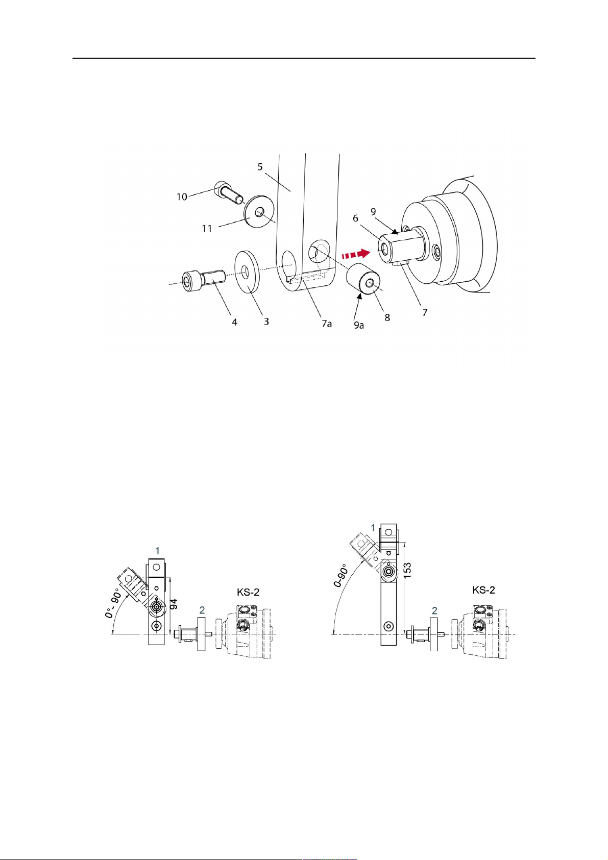
5.1.1.1 Torch installation with adjustable mount
Torch mounts with a central clamping assembly can only be fastened on the journal of the
mounting flange. For this, the mounting flange must be fastened first.
1. If applicable, carefully press the cylindrical pins (1) into the corresponding holes in the
mounting flange. The pins should protrude by approximately 5 mm (0.2 in.).
2. Position the mount on the safety-off mechanism RTKS-2 and carefully insert the
cylindrical pins (1) into the holes provided. In doing so, take the later position of the
torch into account. Two mounting positions may be potentially possible.
3. Then screw down the mounting flange evenly using the enclosed cylinder screws with
hexagon socket (2).
HINWEIS!
The maximum tightening torque for the cylinder screw (2) is 7.1 Nm (62.8
in.lb) and the property class category is 8.8.
0463 373 101
- 26 -
© ESAB AB 2018
5 INSTALLATION
4. Unscrew the axial cylinder screw with hexagon socket (4) out of the mounting flange
together with the washer (3).
1 - Cylindrical pins Ø4×14 3 - Washer Ø9 mm
2 - Cylinder screw with hexagon socket
M6×16
4 - Axial cylinder screw with hexagon
socket M8×16
5. Place the torch mount (5) onto the journal (6) of the mounting flange, paying attention
while doing so to the exact alignment of the feather key (7) and the corresponding
groove (7a).
6. Insert the clamping mandrel (8) into the lateral hole (see illustration) and position it so
that the mating surfaces (9a) of the clamping mandrel rest on the mating surface (9) of
the journal.
0463 373 101
- 27 -
© ESAB AB 2018
5 INSTALLATION
7. Fix the clamping mandrel from the opposite side using the M6 cylinder screw with
hexagon socket (10) and the Ø22 mm washer (11).
8. Screw the axial cylinder screw (4) with the Ø9 mm washer (3) into the mounting flange
and tighten firmly.
3 - Washer Ø9 mm 8 - Clamping mandrel
4 - Axial cylinder screw with hexagon
9 - Mating surface of mounting flange
socket M8×16
5 - Torch mount 9a - Mating surfaces of clamping mandrel
6 - Mounting flange journal 10 - Cylinder screw with hexagon socket
M6×30
7 Feather key 11 - Washer Ø22×6.4 mm
7a - Groove for feather key
5.1.2 Standard arm cable assembly for KS-2 and FL-2
The cable assembly must be aligned to the intended use in length and design. The type of
cooling for the torch and the cable assembly must be the same (either gas or water cooled
respectively). In order to prevent damage to the torch system and other components, it is
imperative to observe the following instructions.
0463 373 101
- 28 -
© ESAB AB 2018

5 INSTALLATION
VORSICHT!
• Coordinate the length and design of the cable assembly to suit the range of
action of the robot.
• Do not bend, compress or overstretch the cable assembly.
• Fix the cable assembly such that is can be moved freely and cannot become
entangled.
• Any additional holding devices possibly installed, for example a balancer,
must not crush or bend the cable assembly.
• Extreme turning movements must be avoided in which the cable assembly
may become twisted.
• Chafing on the robot or other objects must be excluded.
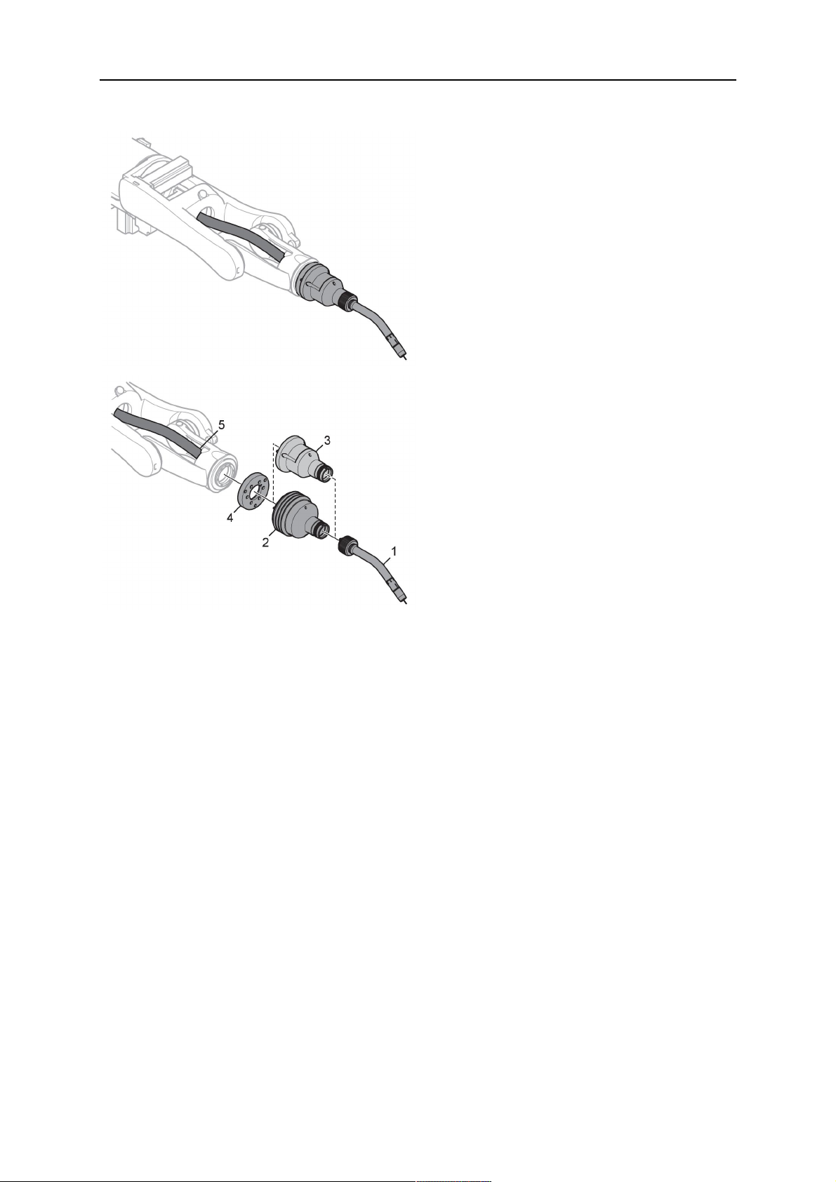
1. Unscrew the cylinder screws (1) and lift off the top section (2) of the torch mount.
2. Insert the feather key (4) into the recess of the neck support flange (3) from below.
3. Align the neck support flange (3) including the feather key (4) to the groove (5) of the
torch mount and push into the groove right up to the stop of the flange.
4. Hold the cable assembly in this position and simultaneously place the top section (2)
back onto the torch mount. First screw both cylinder screws (1) loosely in to about the
same length, then tighten alternately. The top section (2) of the mount should have an
even gap to the bottom section.
The front part of the cable assembly is directly clamped into the torch mount (see
illustration below).
1 - Cylinder screws 4 - Feather key
2 - Torch mount top section 5 - Groove for feather key
3 - Neck support flange
5.1.3 RTKS-2 wire feeder connection
In order to be able to create the connection, the cable assembly must be mounted as
described in the "Installing the cable assembly" section and equipped following "Installing the
wire guide" section. Only then can the central and media connection take place. Proceed as
described below:
0463 373 101
- 29 -
© ESAB AB 2018

5 INSTALLATION
1. Connect the central connector of the cable assembly (2) to the wire feeder cabinet
socket. Tighten the central connector sleeve nut fingertight. Do not use tools.
1 - Burndy Connector 4 - Return of heated water (red cap)
2 - EURO central connector 5 - Return of heated water (red cap)
3 - Air blow-out 6 - Main Wire feeder
2. For water cooled systems. Connect the water hoses to the cooling circuit. The end of
the hose marked blue (4) is connected to the water outlet, and the end marked red (5)
is connected to the water return.
3. Connect the blow-out line (3) to the corresponding connection of the feeder.
4. Connect the Burndy Connector to the wire feeder. (1) to the feeder. See section
"Electrical connections".
HINWEIS!
All hoses and the control line must be installed so they can not bend or get
damaged!
5.1.4 RTKS-2 electrical connections
5.1.4.1 RTKS-2 safety-off mechanism connection
The switch for the safety-off functionality RTKS-2 is connected through the control cable,
see (3) in the illustration below. This connects to the RTKS-2 unit via the 4-pole plug (4) that
contains circuits for the push-button (6) and the safety-off signal (7).
If a collision is detected, the control circuit for the safety-off signal (7), which is normally
closed, will be interrupted.
Rating of the control circuit: max. 48 V / 1 A
0463 373 101
- 30 -
© ESAB AB 2018

5 INSTALLATION
2 - Burndy connector 5 - RTKS-2 connector for control cable plug
4 - Control cable plug
Burndy-Steckverbinderstifte
A. Tastsinn-Gasdüse
C. Kollisionssensor
D. Kollisionssensor
F. 0V
G. + Motorspannung
H. - Motorspannung
E. Kriechgang
If the robot control provides a control circuit for nozzle sense functionality, the connection is
accomplished with a 1-wire connection.
Rating of the control circuit: max 50 V / 5 A.
GEFAHR!
If the nozzle sense function is not being used, the open end of the control cable on
the power source connection side must be properly isolated in order to avoid short
circuits. During certain problems on the torch head, the full welding potential may be
present on this cable.
VORSICHT!
After detection of contact (gas nozzle on work piece), quickly reduce or cut off the
maximum current in the nozzle sense circuit in order to avoid overloading of the
system.
Allowed load max. 1 minute at the rated nominal current.
5.1.5 RTKS-2 Torch installation
Continue according to section "Torch installation".
0463 373 101
- 31 -
© ESAB AB 2018

5 INSTALLATION
5.2 RTFL-2 standard arm installation
5.2.1 RTFL-2 rigid mount
1. Position the RT FL-2 (2) with the index pin on the robot arm and fix it with the hexagon
socket screw included.
The FL-2 is directly compatible with robots with tool flange according to DIN ISO
9409-1-A40 (diameter 40mm, 4×M6). If the rigid mount does not fit, use an adapter
flange (3).
HINWEIS!
Ensure that the index pin is located correctly. The maximum torque of 1.2Nm
(10.5in.lb) must be observed for the fastening of the adapter flange screws.
Prevent self-loosening of the screws by using suitable thread locking
measures.
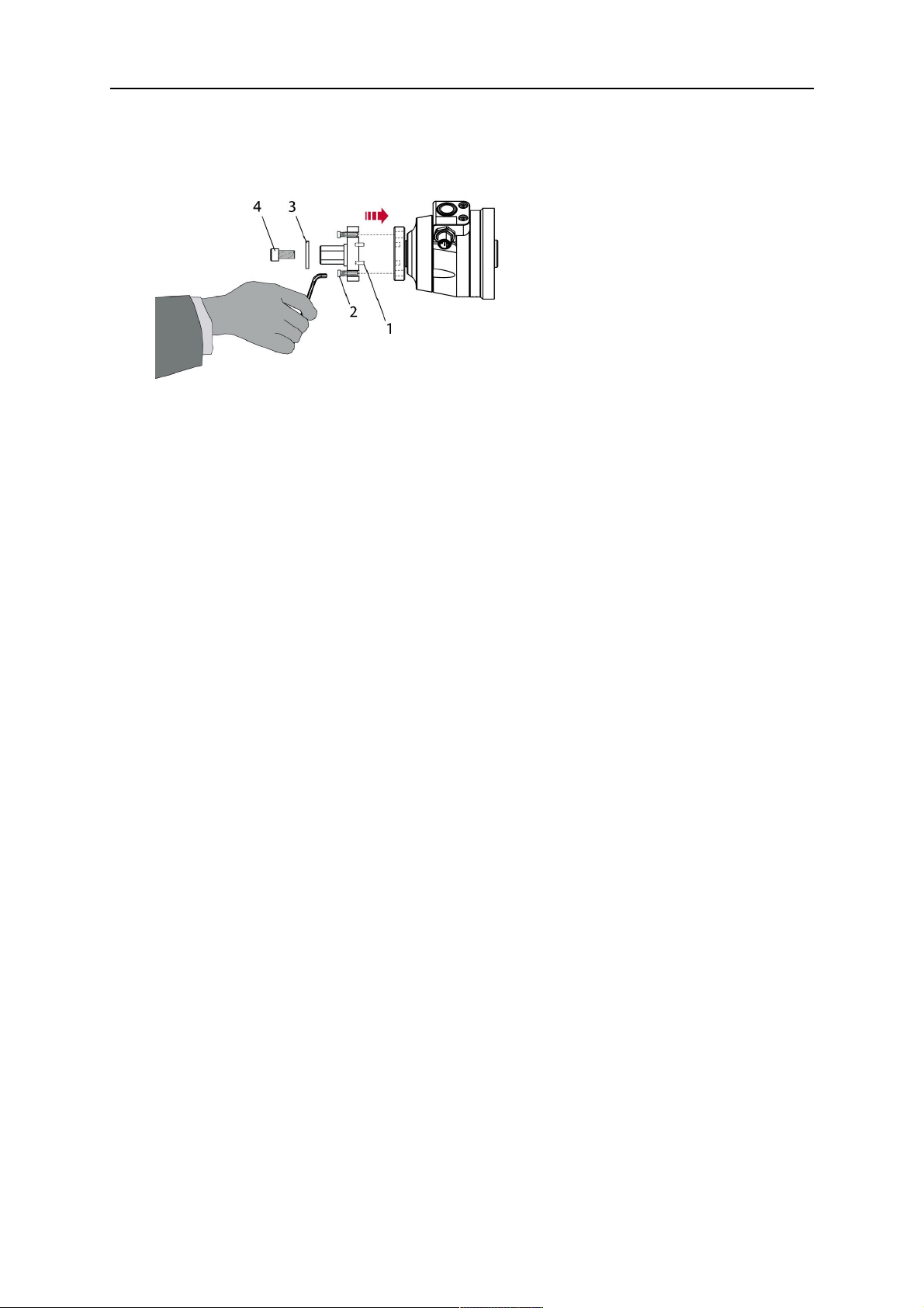
2. Install torch mount (1). Only torch mounts having a hole pattern equivalent with the
mounting surface may be attached. If necessary, carefully press the cylindrical pins (4)
into the corresponding holes in the bracket. The pins should protrude by
approximately 5mm (0.2in.). Position the torch mount on the RTFL-2 (2) and
carefully insert the cylindrical pins (4) into the holes provided. Take the position of the
torch into account. Two mounting positions may be potentially possible.
3. Screw the mount evenly using the enclosed cylinder screws with hexagon socket (5).
HINWEIS!
The maximum tightening torque for the cylinder screw (5) is 6Nm (53in.lb)
and the property class category is 8.8.
0463 373 101
- 32 -
© ESAB AB 2018

5 INSTALLATION
4 - Cylindrical pins Ø4×20
5 - Cylinder screw with hexagon socket M6
DIN 912 (length of the screw depending on
the torch mount)
Side view
Torch installation with adjustable mount
Torch mounts with a central clamping assembly can only be fastened on the journal of the
mounting flange. For this, the mounting flange must be fastened first.
1. If applicable, carefully press the cylindrical pins (1) into the corresponding holes in the
mounting flange. Avoid the formation of burrs. The pins should protrude by
approximately 5 mm (0.2 in.).
2. Position the mount on the RTFL-2 and carefully insert the cylindrical pins (1) into the
holes provided. In doing so, take the later position of the torch into account. Two
mounting positions may be potentially possible.
3. Then screw down the mounting flange evenly using the enclosed cylinder screws with
hexagon socket (2).
HINWEIS!
The maximum tightening torque for the cylinder screw (2) is 7.1 Nm (62.8
in.lb) and the property class category is 8.8.
4. Unscrew the axial cylinder screw with hexagon socket (4) out of the mounting flange
together with the washer (3).
1 - Cylindrical pins Ø4×14 3 - Washer Ø9 mm
2 - Cylinder screw with hexagon socket
M6×16
4 - Axial cylinder screw with hexagon
socket M8×16
5. Place the torch mount (5) onto the journal (6) of the mounting flange, paying attention
while doing so to the exact alignment of the feather key (7) and the corresponding
groove (7a).
0463 373 101
- 33 -
© ESAB AB 2018

5 INSTALLATION
6. Insert the clamping mandrel (8) into the lateral hole (see illustration) and position it so
that the mating surfaces (9a) of the clamping mandrel rest on the mating surface (9) of
the journal.
7. Fix the clamping mandrel from the opposite side using the M6 cylinder screw with
hexagon socket (10) and the Ø22 mm washer (11).
8. Screw the axial cylinder screw (4) with the Ø9 mm washer (3) into the mounting flange
and tighten firmly.
3 - Washer Ø9 mm 8 - Clamping mandrel
4 - Axial cylinder screw with hexagon
9 - Mating surface of mounting flange
socket M8×16
5 - Torch mount 9a - Mating surfaces of clamping mandrel
6 - Mounting flange journal 10 - Cylinder screw with hexagon socket
M6×30
7 - Feather key 11 - Washer Ø22×6.4 mm
7a - Groove for feather key
5.2.2 RTFL-2 torch installation
Continue according to section "Torch installation".
5.3 RTKSC-2 hollow wrist system installation
5.3.1 RTKSC-2 mount with safety off mechanism
VORSICHT!
For hollow wrist systems make sure that the clear space around the robot is at least
Ø45 mm (1.8 in.) around the wrist and 50 mm (2.0 in.) near the wire feeder.
0463 373 101
- 34 -
© ESAB AB 2018

5 INSTALLATION
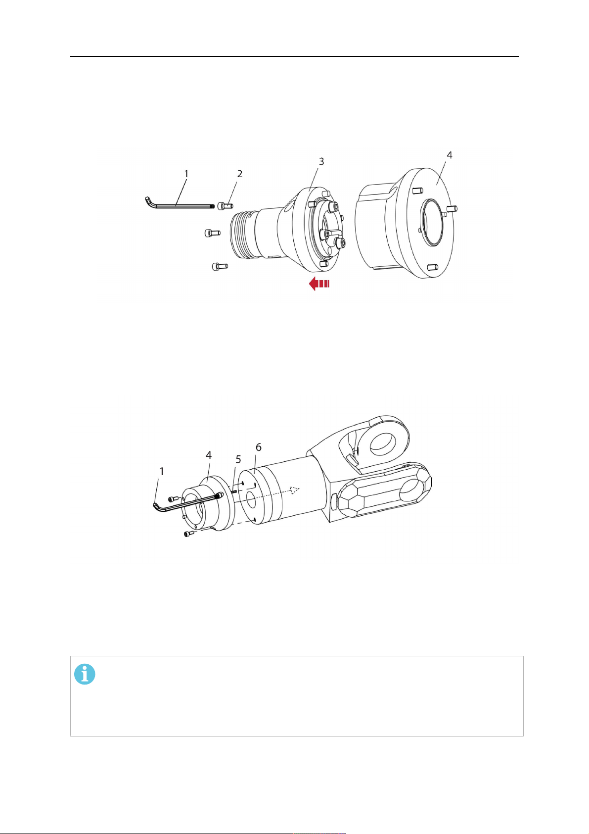
1. Remove the three screws (2) from the front cover (3) of the torch mount and carefully
pull the cover off the RTKSC-2 main body (5). Take care not to damage the micro
switches installed inside the assembly.
1 - Hexagon wrench 4 mm 4 - Rubber boot
2 - 3× M5×12 screws 5 - RT KSC-2 main body
3 - RT KSC-2 front cover
1. Pull off the rubber boot (4) from the RTKSC-2 main body (5) to the front.
2. Now position the RTKSC-2 main body (5) on the adapter flange (7) so that the index
pin is correctly seated. Attach with the screws (6) enclosed.
3. Reinstall the rubber boot (4) on the RTKSC-2 main body (5) and make sure it is
correctly located in the grooves on the front and back flange.
4. Istall the adapter flange (7) on the robot.
Fastening torque max. 2.2 Nm (19.5 in.lb).
1 - Hexagon wrench 4 mm 3 - 3× M5×12 hexagon socket screws
2 - Rubber boot 4 - Adapter flange
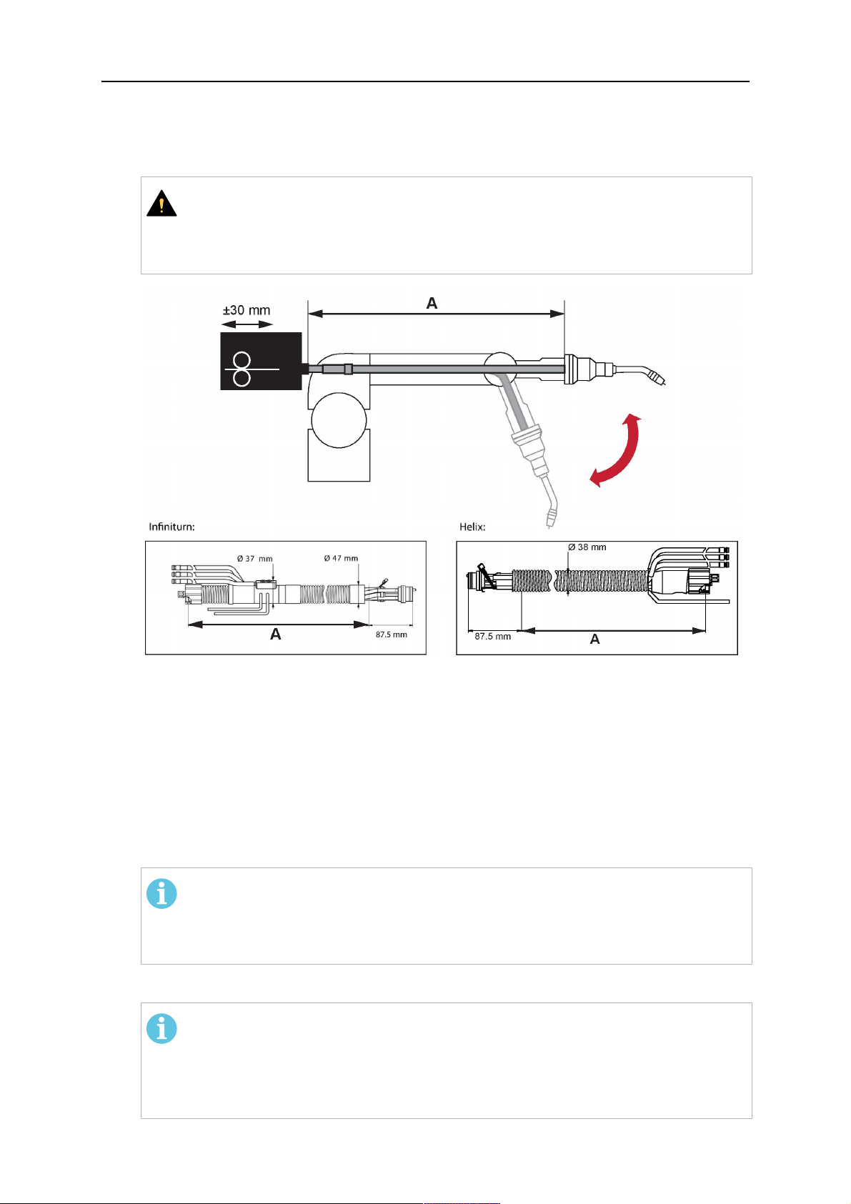
5.3.2 Mounting the cable assembly
HINWEIS!
In order to adjust the wire feeder position to the cable assembly length, it must be
mounted on an adjustable support with a possible movement of ±2-3cm (±1in.) to
the back and to the front. The length of the cable assembly must be determined
from the centred mounting position of the wire feeder.
1. Move the robot arm into a completely straight position, see illustration below. Make
sure that (1) axis 6 (rotation around the torch axis) is in 0° position.
2. Move the feeder (3) completely to the back in order to create space for inserting the
cable assembly. If it is not possible to move the feeder sufficiently, it should be
removed from the robot.
0463 373 101
- 35 -
© ESAB AB 2018

5 INSTALLATION
3. Insert the cable assembly with the coupling (2) first into the robot arm and feed it
through the robot wrist.
4. The feeder should only be installed again after the correct mounting position with
respect to the cable length has been determined. (See section "Installing the cable
assembly").
VORSICHT!
Axis 6 must be in 0° position.
5.3.2.1 RTKSC-2 feeder cabinet connections
When installed for the first time, the position of the wire feeder cabinet must be adjusted to
the length of the cable assembly. First, the robot arm must be fully extended (straight).
VORSICHT!
As long as the correct position of the feeder corresponding to the length of the cable
assembly has not been determined, be careful when moving the robot arm and
avoid overstretching the cable. It is helpful to loosen the positioning screws of the
feeder before moving the robot arm to allow the feeder to follow the cable assembly.
0463 373 101
- 36 -
© ESAB AB 2018

5 INSTALLATION
1. Loosen the sliding mechanism of the wire feeder and connect the cable assembly.
2. Now adjust the position of the wire feeder to suit the length of the Infiniturn or Helix
cable, as indicated with "A" in the illustration below.
VORSICHT!
When adjusting the position of the feeder cabinet, make sure that the cable
assembly is not under stress when the robot arm is in stretched-out position.
It is normal for the cable assembly to sag slightly, it should never be taut.
3. Before securing the wire feeder in its permanent position, ensure that the Euro
connectors are tightly connected. Then turn the torch mount down and up again
(rotating on the axis 5), in order not to tighten the cable assembly too much against
the feeder (see illustration above). Once this is done, tighten the feeder in that
position.
4. For water cooled systems, connect the water lines to the cooling circuit. See section
"Cable assemblies for hollow wrist systems" in the TECHNICAL DATA chapter for
indications.
The hose with the blue rubber cap is for cooling water to the torch, the hose with the
red rubber cap returns the heated water. Make sure the hoses will not kink or get
otherwise blocked.
HINWEIS!
A Helix cable assembly used for a gas cooled system must not be connected
to a cooling circuit. As the water connections are not needed, they may be cut
off.
5. Connect the blow-out hose (black rubber cap) to the corresponding outlet of the wire
feeder.
HINWEIS!
If the blow-out function is not used, the blow-out hose must be sealed with the
rubber cap enclosed. With Infiniturn systems, the blow-out air must be
supplied to the corresponding connection hose, if it is not permitted to connect
blow-out air to the shield gas connection!
6. Install the necessary plug on the control cable and connect it to the safety off circuit
interface of the wire feeder (see section "Electrical connections").
0463 373 101
- 37 -
© ESAB AB 2018

5 INSTALLATION
5.3.3 RTKSC-2 cable assembly
The cable assembly must be aligned to the intended use in length and design. The type of
cooling for the torch and the cable assembly must be the same (either gas or water cooled
respectively). In order to prevent damage to the torch system and other components, it is
imperative to observe the following instructions.
VORSICHT!
• Coordinate the length and design of the cable assembly to suit the range of
action of the robot.
• Do not bend, compress or overstretch the cable assembly.
• Fix the cable assembly such that is can be moved freely and cannot become
entangled.
• Any additional holding devices possibly installed, for example a balancer,
must not crush or bend the cable assembly.
• Extreme turning movements must be avoided in which the cable assembly
may become twisted.
• Chafing on the robot or other objects must be excluded.
5.3.3.1 RTKSC-2 cable assembly installation
HINWEIS!
For some robots, it may be possible to deviate from this order, and first connect the
cable assembly to the RTKSC-2, then thread the cable from the front through the
robot arm. If in doubt, follow the suggested order.
1. Loosen the three screws (7) with the associated washers and remove them from the
RTKSC-2 cover (1). See illustration below.
2. Install the supplied O-rings (4) into the grooves in the cover (1).
3. Pull the cable assembly approximately 15 cm (6 in.) from the main body (3).
0463 373 101
- 38 -
© ESAB AB 2018

5 INSTALLATION
4. Insert the coupling (2) into the socket of the cover (1) as shown. Align the index pin (6)
with the index hole (5) in the main body and insert completely.
HINWEIS!
Make sure that the position of the O-rings are not shifted by the index pin
during the assembly.
1 - RTKSC-2 cover 5 - Index hole
2 - Coupling 6 - Index pin
3 - RTKSC-2 main body 7 - 3× M5×35 screws
4 - 3× O-ring for water cooled systems 11 - Control cable connector
5. Insert the three screws (7) with the associated washers (8) and tighten gently with the
enclosed hexagonal wrench, see below illustration.
Fastening torque approximately 2 Nm (18 in.lb).
0463 373 101
- 39 -
© ESAB AB 2018

5 INSTALLATION
6. If present, insert the control cable plug (10) into the connector (11) and make sure it is
firmly seated.
7 - 3× M5×35 screw 11 - Control cable connector
8 - Washer 12 - 2× Micro switch
10 - Control cable plug 13 - Index pin
7. Gently push back the cable assembly into the robot arm and carefully seat the
RTKSC-2 cover (1) in place. Observe the index pin (13) to be in the correct position.
Make sure the two micro switches (12) are not damaged if present.
8. Insert the three M5 screws (14) and tighten without excessive force.
13. Index pin
14. 3× M5×12 screws
0463 373 101
- 40 -
© ESAB AB 2018

5 INSTALLATION
5.3.3.2 RTKSC-2 electrical connections
HINWEIS!
After connecting the control cable, secure the cable in order to protect it from getting
caught while the robot is moving.
Usually, the control cable will be directly connected to the wire feeder. See the
manufacturer's documentation for details. The link to the robot control is then
implemented via the power source controller.
RTKSC-2 safety-off mechanism connection
The switch for the safety-off functionality RTKSC-2 is connected through the control cable,
see (3) in the illustration below. This connects to the RTKSC-2 unit via the control cable plug
(1).
The safety-off signal requires a 2-wire connection (black/black) to the safety-off circuit in the
robot control (5).
If a collision is detected, the control circuit (normally closed) will be interrupted (4).
Rating of the control circuit: max. 48 V / 1 A.
1 - Control cable plug 3 - Burndy connector VVV
2 - EURO central connector
Burndy-Steckverbinderstifte
A. Tastsinn-Gasdüse
C. Kollisionssensor
D. Kollisionssensor
F. 0V
G. + Motorspannung
H. - Motorspannung
E. Kriechgang
RTKSC-2 nozzle sense function connection
If the robot control provides a control circuit for nozzle sense functionality.
The connection is accomplished with a 2-wire connection (black/black) to the nozzle sense
circuit in the robot control (5), see illustration below.
0463 373 101
- 41 -
© ESAB AB 2018

5 INSTALLATION
Usually, the control cable will be directly connected to the wire feeder. See the
manufacturer's documentation for details. The link to the robot control is then implemented
via the power source robot interface.
Rating of the control circuit: max. 50 V / 5 A.
GEFAHR!
If the nozzle sense function is not being used, the open end of the control cable on
the power source connection side must be properly isolated in order to avoid short
circuits. During certain problems on the torch head, the full welding potential may be
present on this cable.
VORSICHT!
After detection of contact (gas nozzle on work piece), quickly reduce or cut off the
maximum current in the nozzle sense circuit in order to avoid overloading of the
system.
Allowed load max. 1 minute at the rated nominal current.
1 - Control cable plug 3 - Control cable
2 - EURO central connector
5.3.4 RTKSC-2 torch installation
Continue according to section "Torch installation".
0463 373 101
- 42 -
© ESAB AB 2018
5 INSTALLATION
5.4 RTFLC-2 installation
5.4.1 RTFLC-2 mount
1. Remove the three M5 screws (2) from the front cover (3) of the RT FLC-2 torch mount
and carefully pull the cover off the main body (4).
1 - Hexagon wrench 4 mm 3 - RT FLC-2 front cover
2 - 3× M5×12 screws 4 - RT FLC-2 main body
2. Now position the RT FLC-2 main body (4) on the adapter flange (6) so that the index
pin is correctly seated. Attach with the screws (5) enclosed
Fastening torque max. 2.2 Nm (19.5 in.lb).
1 - Hexagon wrench 4 mm 5 - 3× M5×12 hexagon socket screws
4 - RT FLC-2 main body 6 - Adapter flange
5.4.2 RTFLC-2 wire feeder connection
5.4.2.1 Feeding through the robot arm
HINWEIS!
In order to adjust the wire feeder position to the cable assembly length, it must be
mounted on an adjustable support with a possible movement of ± 2-3 cm (± 1 in.) to
the back and to the front. The length of the cable assembly must be determined
from the centred mounting position of the wire feeder.
0463 373 101
- 43 -
© ESAB AB 2018

5 INSTALLATION
1. Move the robot arm into a completely straight position, see illustration below. Make
sure that (1) axis 6 (rotation around the torch axis) is in 0° position.
2. Move the feeder (3) completely to the back in order to create space for inserting the
cable assembly. If it is not possible to move the feeder sufficiently, it should be
removed from the robot.
3. Insert the cable assembly with the coupling (2) first into the robot arm and feed it
through the robot wrist.
4. The feeder should only be installed again after the correct mounting position with
respect to the cable length has been determined. (See section "Installing the cable
assembly").
VORSICHT!
Important! Axis 6 must be in 0° position.
5.4.2.2 RTFLC-2 feeder cabinet connections
When installed for the first time, the position of the wire feeder cabinet must be adjusted to
the length of the cable assembly. First, the robot arm must be fully extended (straight).
VORSICHT!
As long as the correct position of the feeder corresponding to the length of the cable
assembly has not been determined, be careful when moving the robot arm and
avoid overstretching the cable. It is helpful to loosen the positioning screws of the
feeder before moving the robot arm to allow the feeder to follow the cable assembly.
0463 373 101
- 44 -
© ESAB AB 2018
5 INSTALLATION
1. Loosen the sliding mechanism of the wire feeder and connect the cable assembly.
Refer to the instruction of the feeder manufacturer.
2. Now adjust the position of the wire feeder to suit the length of the Infiniturn or Helix
cable, as indicated with "A" in the illustration below.
VORSICHT!
When adjusting the position of the feeder cabinet, make sure that the cable
assembly is not under stress when the robot arm is in stretched-out position.
It is normal for the cable assembly to sag slightly, it should never be taut.
3. Before securing the wire feeder in its permanent position, ensure that the Euro
connections are tightly connected. Then turn the torch mount down and up again
(rotating on the axis 5), in order not to tighten the cable assembly too much against
the feeder (see illustration above). Once this is done, tighten the feeder in that
position.
4. For water cooled systems, connect the water lines to the cooling circuit. See section
"Cable assemblies for hollow wrist systems" in the TECHNICAL DATA chapter for
indications.
The hose with the blue rubber cap is for cooling water to the torch, the hose with the
red rubber cap returns the heated water. Make sure the hoses will not kink or get
otherwise blocked.
HINWEIS!
A Helix cable assembly used for a gas cooled system must not be connected
to a cooling circuit. As the water connections are not needed, they may be cut
off.
5. Connect the blow-out hose (black rubber cap) to the corresponding outlet of the wire
feeder.
HINWEIS!
If the blow-out function is not used, the blow-out hose must be sealed with the
rubber cap enclosed. With Infiniturn systems, the blow-out air must be
supplied to the corresponding connection hose, if it is not permitted to connect
blow-out air to the shield gas connection!
0463 373 101
- 45 -
© ESAB AB 2018

5 INSTALLATION
6. Install the necessary plug on the control cable and connect it to the safety off circuit
interface of the wire feeder (see section "Electrical connections").
5.4.3 RTFLC-2 cable assembly
The cable assembly must be aligned to the intended use in length and design. The type of
cooling for the torch and the cable assembly must be the same (either gas or water cooled
respectively). In order to prevent damage to the torch system and other components, it is
imperative to observe the following instructions.
VORSICHT!
• Coordinate the length and design of the cable assembly to suit the range of
action of the robot.
• Do not bend, compress or overstretch the cable assembly.
• Fix the cable assembly such that is can be moved freely and cannot become
entangled.
• Any additional holding devices possibly installed, for example a balancer,
must not crush or bend the cable assembly.
• Extreme turning movements must be avoided in which the cable assembly
may become twisted.
• Chafing on the robot or other objects must be excluded.
5.4.3.1 RTFLC-2 cable assembly installation
In a hollow wrist system the recommended order of installation is to feed the cable assembly
through the robot arm before connecting the cables to the torch mount.
When the cable assembly is correctly installed in the hollow wrist, continue the installation
according to the procedure described below.
HINWEIS!
For some robots, it may be possible to deviate from this order, and first connect the
cable assembly to the RTKSC-2 and RTFLC-2, then thread the cable from the front
through the robot arm. If in doubt, follow the suggested order.
1. Loosen the three screws (7) with the associated washers and remove them from the
RTFLC-2 cover (1). See illustration below.
2. Install the supplied O-rings (4) into the grooves in the cover (1). For gas cooled
systems, only one O-ring (4a) is needed, for water cooled systems all three O-rings
are needed.
3. Pull the cable assembly approximately 15 cm (6 in.) from the main body (3).
0463 373 101
- 46 -
© ESAB AB 2018

5 INSTALLATION
4. Insert the coupling (2) into the socket of the cover (1) as shown. Align the index pin (6)
with the index hole (5) in the main body and insert completely.
HINWEIS!
Take great care that the position of the O-rings is not shifted by the index pin
during the assembly.
1 - RT FLC-2 cover 5 - Index hole
2 - Coupling 6 - Index pin
3 - RT FLC-2 main body 7 - 3× M5×35 screws
4 - 3× O-ring for water cooled systems 11 - Control cable connector
5. Insert the three screws (7) with the associated washers (8) and tighten gently with the
enclosed hexagonal wrench, see below illustration.
Fastening torque approximately 2 Nm (18 in.lb).
0463 373 101
- 47 -
© ESAB AB 2018

5 INSTALLATION
6. If present insert the control cable plug (10) into the connector (11) and make sure it is
firmly seated.
7 - 3× M5×35 screw 11 - Control cable connector
8 - Washer 12 - 2× Micro switch
10 - Control cable plug 13 - Index pin
7. Gently push back the cable assembly into the robot arm and carefully seat the
RTFLC-2 cover (1) in place. Observe the index pin (13) to be in the correct position.
Make sure the two micro switches (12) are not damaged if present.
8. Insert the three M5 screws (14) and tighten without excessive force.
13 - Index pin 14 - 3x M5x12 screws
0463 373 101
- 48 -
© ESAB AB 2018

5 INSTALLATION
5.4.4 RTFLC-2 electrical connections
HINWEIS!
After connecting the control cable, secure the cable in order to protect it from getting
caught while the robot is moving.
Usually, the control cable will be directly connected to the wire feeder. See the
documentation of the manufacturer for details. The link to the robot control is then
implemented via the power source controller.
5.4.4.1 RTFLC-2 hollow wrist system with Infiniturn cable assembly
Connecting the nozzle sense function
If the robot control provides a control circuit for nozzle sense functionality.
The connection is accomplished with a 2-wire connection (black/black) to the nozzle sense
circuit in the robot control (5), see illustration below.
Usually, the control cable will be directly connected to the wire feeder. See the
manufacturer's documentation for details. The link to the robot control is then implemented
via the power source robot interface.
Rating of the control circuit: max. 50 V / 5 A.
GEFAHR!
If the nozzle sense function is not being used, the open end of the control cable on
the power source connection side must be properly isolated in order to avoid short
circuits. During certain problems on the torch head, the full welding potential may be
present on this cable.
VORSICHT!
After detection of contact (gas nozzle on work piece), quickly reduce or cut off the
maximum current in the nozzle sense circuit in order to avoid overloading of the
system.
Allowed load max. 1 minute at the rated nominal current.
1 - Control cable plug 3 - Control cable
2 - EURO central connector
0463 373 101
- 49 -
© ESAB AB 2018

5 INSTALLATION
5.4.4.2 RTFLC-2 hollow wrist system with Helix cable assembly
Connecting the nozzle sense function
If the robot control provides a control circuit for nozzle sense functionality.
The connection is accomplished with a 1-wire connection (green) to the nozzle sense circuit
in the robot control (5), see illustration below.
Usually, the control cable will be directly connected to the wire feeder. See the
manufacturer's documentation for details. The link to the robot control is then implemented
via the power source robot interface.
Rating of the control circuit: max. 50 V / 5 A.
GEFAHR!
If the nozzle sense function is not being used, the open end of the control cable on
the power source connection side must be properly isolated in order to avoid short
circuits. During certain problems on the torch head, the full welding potential may be
present on this cable.
VORSICHT!
After detection of contact (gas nozzle on work piece), quickly reduce or cut off the
maximum current in the nozzle sense circuit in order to avoid overloading of the
system.
Allowed load max. 1 minute at the rated nominal current.
1 - Control cable plug 3 - EURO central connector
2 - Control cable 4 - Burndy connector
5.5 Torch installation
Be sure to use the correct version of the torch mount and cable assembly (water or gas
cooled).
5.5.1 Torch neck equipment
The torch neck, see (1) in the illustration below, must always be equipped to suit the wire
diameter and material.
0463 373 101
- 50 -
© ESAB AB 2018

5 INSTALLATION
1. Select the correct wire guide, contact tip (4), tip holder (2), gas nozzle (5), and gas
diffuser/spatter protection (3). You will find an exact overview and possible alternative
equipment elements for various torch models in the spare parts list. Only use original
ESAB parts; only then is the fitting accuracy ensured.
2. Firmly tighten the tip holder and the contact tip using a suitable tool for example the
enclosed monkey wrench.
3. When using a split wire guide, remove the installed guide nipple including the o-ring
from the torch flange upon delivery if necessary (see section "Installing the neck
liner").
VORSICHT!
The torch must be completely equipped before welding, especially the gas
diffuser and/or spatter protection and all necessary insulators have to be
installed according to the spare parts list. Welding without these items may
cause immediate destruction of the torch.
1 - Torch neck 4 - Contact tip
2 - Tip holder 5 - Contact tip
3 - Gas diffuser
5.5.2 Aristo RT torch neck installation
HINWEIS!
Check the O-rings on the flange of the torch neck before mounting. Replace the
O-rings if damaged or lost. Missing or faulty O-rings will lead to leaks of shielding
gas and coolant.
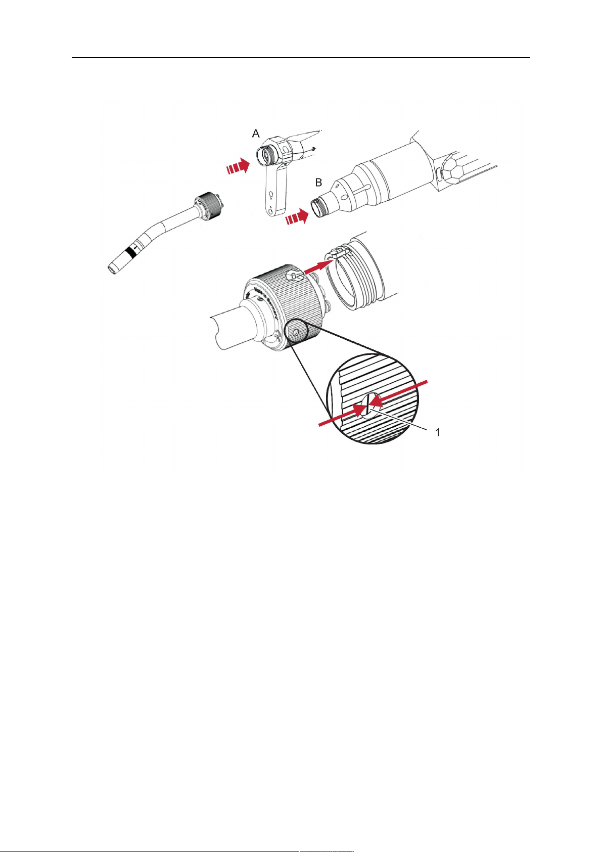
1. For hollow wrist systems, insert the torch into the torch mount in the correct
orientation, so that the locator pin fits into the slot of the RTKSC-2 or RTFLC-2
interface, see (A) in the illustration below. For standard systems, attach the torch to
the RT flange of the cable assembly, (B) in the illustration below.
Installation is only possible in the correct orientation.
2. Tighten the locking nut of the torch neck.
HINWEIS!
Only tighten by hand, never use tools or excessive force.
0463 373 101
- 51 -
© ESAB AB 2018
5 INSTALLATION
3. The correct seating of the torch can be checked by means of the window (1). If the
torch has been correctly mounted, no gap should be seen through the window (1).
5.6 Installing the wire guide for standard and hollow Wrist arm
Installing the wire guide
Choose the wire guide or liner depending on the filler wire material and diameter to be used,
see the spare parts list. Accurate performance of the system can only be guaranteed when
using original ESAB wire guides.
The recommended wire guide is the split wire guide, which consists of the neck liner and a
separate guide in the cable assembly. The front part of the wire guide, which is most
stressed, can be exchanged easily and independently of the cable assembly wire guide.
For correct installation, the following steps must be followed (example for Euro central
connector).
5.6.1 Installing the neck liner
The neck liner must be selected to fit the material and diameter of the welding wire, see the
spare parts list.
0463 373 101
- 52 -
© ESAB AB 2018

5 INSTALLATION
1. If present, remove the central guide nipple (1), from the torch neck using a hexagon
wrench (size 6 mm) or a large flat-blade screwdriver.
HINWEIS!
The guide nipple (1) can only be used with one-piece liners and must not be
used with the standard RT or hollow wrist system.
2. When replacing the neck liner:
Unfasten the sleeve nut and remove the torch neck.
Unfasten the liner nipple using a hexagon wrench (size 6 mm) and remove nipple and
liner from the torch neck.
3. Remove the gas nozzle and the contact tip.
4. Insert the new neck liner (2) into the torch. Carefully tighten the guide nipple using a
suitable tool, e.g. a hex-wrench (size 6 mm) or a large flat-blade screwdriver.
5. Cut the neck liner flush with the tip holder and remove the neck liner from the torch.
6. Install the contact tip.
7. Insert the neck liner again. It will be stopped by the contact tip. Measure the excess
liner sticking out of the neck.
8. Remove the liner again and shorten the front end by the measured length. Carefully
deburr the edge and make sure that the inner hole is not blocked.
9. Reinstall the neck liner and tighten the guide nipple in the neck.
5.6.2 Installing a split wire guide in the cable assembly
The correct liner must be inserted to suit the filler material and the wire diameter, see the
spare parts list.
The wire guide is inserted through the cable assembly from the rear, reaching the guide
nipple that is installed in the flange where the torch neck will be attached. The following
worksteps must be followed in order to correctly determine the wire guide length. (Example
for Euro central connector).
0463 373 101
- 53 -
© ESAB AB 2018

5 INSTALLATION
1. For standard RT system: Install the guide nipple (1) in the center hole of the neck
support flange, see illustration A below.
For hollow wrist system: Install the guide nipple (1) into the torch interface of the
RTKSC-2 / RTFLC-2 cover, see illustration B below.
2. Remove the sleeve nut (2) from the central connector, and remove the old wire guide.
3. Insert the wire guide through the central connection and push forwards as far as it will
go into the guide nipple (1), applying light pressure.
VORSICHT!
Ensure that the wire guide has advanced right up to the stop at the front,
rotating and pushing forward gently.
4. Measure the excess length that needs to be cut from the wire guide.
5. Remove the wire guide again and shorten the front end by the measured length.
Steel liner: grind down the burred edges if needed.
Plastic liner: make a clean cut and chamfer the edges (e.g. with a pencil sharpener)
HINWEIS!
Make sure the inner opening of the liner is not obstructed by the cut wire end.
0463 373 101
- 54 -
© ESAB AB 2018

5 INSTALLATION
6. Reinstall the wire guide and attach the sleeve nut (2).
HINWEIS!
For hollow wrist systems where Infiniturn and Helix cable assemblies are
used, wire guides should be installed without tension so that the ends of the
liners may rotate freely.
Important note when using a plastic liner:
The wire channel between the drive rolls of the feeder and the central
connector of the torch must be fitted with a plastic liner. Depending on the
design of the feeder, a piece of plastic liner inserted into a brass guide tube
can be used.
During wire run-in, make sure that the wire is fed correctly into the plastic liner
of the torch. If necessary, remove the cable assembly from the feeder and
insert the wire, then reattach.
5.6.3 Installing a continuous wire guide in the cable assembly
Installing a steel liner
The wire guide is inserted through the cable assembly from the rear and reaches to the
contact tip. The following worksteps must be followed for the correct calculation of the length
(example for Euro central connector):
1. Install the torch (see section "Torch neck equipment").
2. Remove the gas nozzle and contact tip from the torch.
3. Remove the sleeve nut (D) from the Euro connector.
4. Push in the liner through the central connector and fix with the sleeve nut.
5. Cut off the liner flush with the nozzle holder. To determine the thread projection of the
contact tip, pull the liner backwards and screw in the contact tip.
6. Push the liner forwards as far as it will go to the contact tip applying light pressure on
the liner and measure the length to be shortened at the rear.
7. Now remove the liner again and cut the excess length measured off it’s front end. If
needed, grind down the burred edges. Make sure the inner opening of the liner is not
obstructed by the cut wire end.
8. The insulation of the liner must be removed after cutting off in the front area, such that
the insulation protrudes out of the RM2 flange by approx. 5 cm. For this, briefly
remove the torch neck.
9. Push the liner back in again and fix with the sleeve nut (D), see above. Re-install the
gas nozzle.
0463 373 101
- 55 -
© ESAB AB 2018

5 INSTALLATION
Installing a plastic liner
1. Mount the torch neck (see section "Torch neck equipment") and equip it with a gas
nozzle and contact tip.
2. Remove the sleeve nut (D) from the Euro connector.
3. Cleanly cut off the liner, slightly break the outer edges, point slightly (e.g. with a pencil
sharpener).
4. Insert the liner through the central connector into the cable assembly with fitted torch.
If it gets stuck, rotate the liner to free it and facilitate installation.
HINWEIS!
Make sure the liner is completely inserted by rotating it and slightly pushing it
forward, until you can feel it has reached its stop.
5. Mount the nipple (B) and the O-Ring (C), move it to the right position and fix it with the
sleeve nut (D) of the Euro central connector.
6. Measure the required overlap needed inside the wire feeder cabinet and cut the liner
accordingly.
5.7 Adjust the narrow gap contact tip
The adjusting tool RT42-NG is designed for the narrow gap torch necks RT42W-NG,
RT42G-NG and RT 82W-0°NG, torches with curved narrow gap contact tip. It facilitates the
precisely repeatable and fast changing of the curved contact tip.
HINWEIS!
The adjusting tool must be securely fastened to a stable base, in order to prevent
the position of the device in relation to the robot cannot change unintentionally. If the
exact orientation of the device is lost, the alignment of the contact tip used for the
elaboration of the welding programs can no longer be reproduced with precision.
Select a position within the operating range of the robot for orientation (alignment) of the
contact tip to the torch. Fasten the adjusting tool firmly to a base using the fastening grooves
provided for this purpose. Fastening material is not included with the adjusting tool. Select
fastening material (screws) to suit the existing conditions.
Save all motion sequences and stop positions required to change or align the wearing parts
to a separate robot program.
Before programming the welding tasks: plan at which orientation the contact tip is to stand in
relation to the torch. The torch must then be positioned in the desired rotational position and
the contact tip aligned using the adjusting device. Only then may the welding task be
programmed. If different orientations of the contact tip are required for various welding tasks,
the contact tip has to be aligned to the new position when the welding task is changed.
WARNUNG!
The gas nozzle and the torch head become very hot during welding. Always allow
the torch to cool down before replacing wearing parts or adjusting the contact tip.
0463 373 101
- 56 -
© ESAB AB 2018

5 INSTALLATION
Adjust the contact tip
Move the robot torch to a position parallel to
the opening of the adjusting tool (2). Maintain
a sufficient distance to the work table to be
able to comfortably remove the gas nozzle.
Define this position in your robot program as
the wearing parts change position (stop
position 1).
Remove the gas nozzle by pulling it
downwards. Remove the welding wire in the
contact tip if necessary.
Loosen the counter nut (4) of the contact tip
while counter-holding the nozzle holder at the
wrench flat (3).
Unscrew the contact tip including the counter
nut from the nozzle holder and replace the
nozzle holder if necessary.
Completely screw the counter nut (4) onto the
new contact tip. Screw the contact tip
including the counter nut into the nozzle
holder.
Align the contact tip until it is parallel to the
opening of the adjusting tool. If necessary,
slightly unscrew the contact tip so that it can
be easily turned in both directions.
0463 373 101
- 57 -
© ESAB AB 2018
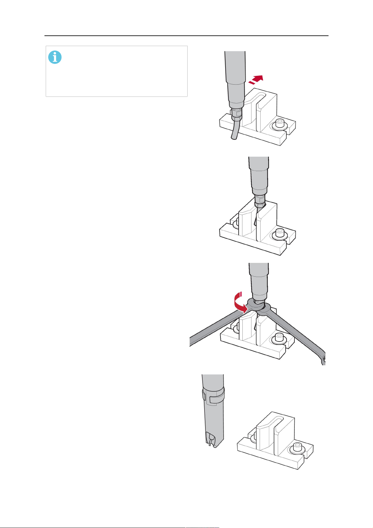
5 INSTALLATION
HINWEIS!
The contact tip must be able to be
easily moved by hand in both
directions in order to enable the
threading of the adjusting tool.
Place the robot torch or contact tip directly in
front of the opening of the adjusting tool (2)
(stop position 2).
Insert it slowly from the front until it is
completely inserted into the device (stop
position 3).
The contact tip was aligned exactly in the
device during insertion. Now cautiously
tighten the counter nut (4) in this position,
while counter holding the nozzle holder at the
wrench flat.
Slowly move the robot torch out of the
adjusting gauge, return to stop position 1 and
push on the gas nozzle as far as it will go.
Allow the welding wire to run into the contact
tip and bring the robot arm into welding
position.
0463 373 101
- 58 -
© ESAB AB 2018

6 OPERATION
6 OPERATION
VORSICHT!
Before starting the system, check the whole installation according to the
manufacturer's instructions and applicable safety regulations.
Check the following to make sure that the system has been installed correctly:
1. Are all parts securely attached (torch, torch mount, flanges, safety-off device, cable
assembly, and wire feeder cabinet)?
2. Are all media hoses connected correctly and protected from damage?
3. Is the EURO central connector or direct connector fastened tightly?
4. Is the cable assembly length correct and suitable for the installation and can the cable
rotate freely? The cable must not be bent sharply. Any risk of the cable getting caught
on another object must be eliminated.
5. Is the control cable of the safety-off circuit connected and functioning? Move torch by
hand to test (RTKSC-2 and RTKS-2 only).
6. Is the torch firmly attached and is it completely equipped?
7. Is the wire guide installed according to the manual?
8. Are all lines and tubes arranged so that they cannot be damaged or bent?
The wire run-in can now be started, either via the wire run-in pushbutton or via the wire run-in
at the feeder.
6.1 Important information for programming (hollow wrist system only)
Fast rotation of axis 6 of the robot will significantly stress the cable assembly. In certain
cases, this can lead to damage or destruction of the cable. In order to maximize the lifetime
of the cable, we strongly suggest respecting the following limitations when programming the
robot.
Position of axis 5 Max. rotational speed of axis 6
0 – 60° 100 % (no limitations)
60° – 80° 300°/sec (approximately 50 % of max. robot speed)
> 80° 120°/sec (approximately 20 % of max. robot speed)
HINWEIS!
The above values are only indications. For information on the exact rotational speed
limits, refer to the individual robot manual or contact the robot supplier.
To reposition the torch quickly, the robot arm may have to be slightly extended first to achieve
a bending angle of max. 60° of axis 5. In this position, the maximum available rotation speed
of axis 6 can be used.
When using the ESAB Helix cable assembly, the max. rotation of ±270° from the neutral
position must not be exceeded.
0463 373 101
- 59 -
© ESAB AB 2018

6 OPERATION
VORSICHT!
While axis 5 is bent more than 60°, the rotational speed of the torch around axis 6
must be limited, see table above.
Otherwise, the cable assembly may be damaged.
0463 373 101
- 60 -
© ESAB AB 2018

7 PFLEGE UND WARTUNG
7 PFLEGE UND WARTUNG
WARNUNG!
Vor der Wartung des Systems muss die Hauptstromversorgung der Anlage
ausgeschaltet werden. Beachten Sie die Sicherheitsvorschriften am Anfang dieses
Handbuchs.
Beschädigte Schweißbrenner oder Kabelbaugruppen dürfen nicht verwendet
werden. Bekannte Mängel müssen vor der erneuten Verwendung der Anlage durch
qualifiziertes Personal beseitigt werden.
WARNUNG!
Verbrennungsrisiko! Sowohl die Gasdüse als auch der Schweißbrennerkopf werden
beim Schweißen sehr heiß. Lassen Sie den Schweißbrenner vor der Durchführung
von Wartungsarbeiten abkühlen.
WARNUNG!
Um Verletzungen oder Schäden an Ihrer Anlage zu vermeiden, befolgen Sie diese
Anweisungen:
1. Die Reparatur der RT KSC-2- oder RT
FLC-2-Schweißbrenner-Befestigung, des RT
KS-2-Sicherheits-Abschaltmechanismus, der Kabelbaugruppe oder der
Infiniturn-Medienkupplung darf nur vom ESAB-Kundendienst durchgeführt
werden.
2. Die Infiniturn-Medienkupplung darf niemals geöffnet werden. Sie enthält
keine vom Benutzer zu wartenden Teile und wird durch die Demontage
zerstört.
3. Zerlegen Sie niemals RT KSC-2 oder RT KS-2. Dies ist ein federbelasteter
Mechanismus. Eine unsachgemäße Handhabung kann zu schweren
Verletzungen führen.
7.1 Obligatorische Prüfungen und Aktionen
Vor jedem Gebrauch:
• Prüfen Sie Schweißbrenner, Kontaktspitze, Gasdüse, Halsummantelung, Kabel und die
gesamte Ausrüstung auf allgemeine Schäden.
HINWEIS!
Um Ausfallzeiten zu minimieren, wird empfohlen, zwischen zwei
Schweißbrennerhälsen zu wechseln, immer einen frisch ausgestatteten sowie
einsatzbereiten Schweißbrennerhals zur Hand zu haben.
Alle 8 Betriebsstunden (je nach Anwendung):
• Tauschen Sie die Kontaktspitze aus.
Täglich:
• Führen Sie eine Funktionsprüfung von Hand des Sicherheits-Abschaltmechanismus
durch.
• Führen Sie eine Sichtprüfung auf Beschädigungen wie z. B. Verformungen oder Risse
durch.
0463 373 101
- 61 -
© ESAB AB 2018

7 PFLEGE UND WARTUNG
• Überprüfen Sie die korrekte Position der Drahtvorschubeinheit. Die Kabelbaugruppe
darf nicht zu stark gespannt sein oder durchhängen.
• Überprüfen Sie die Medienanschlüsse und die Infiniturn-Medienkupplung auf
Undichtigkeiten.
• Führen Sie die Reinigung und Wartung des Schweißbrenners gemäß dem
Schweißbrennerhandbuch durch.
Alle 40 Betriebsstunden (je nach Anwendung):
• Tauschen Sie die Drahtummantelungen aus.
• Tauschen Sie die Halsummantelungen aus.
Wöchentlich oder nach Bedarf, je nach Verwendung:
• Entfernen Sie die Drahtführung und prüfen Sie auf Verschleiß sowie Verschmutzung.
Bei Bedarf austauschen.
Monatlich oder häufiger bei intensiver Nutzung (d. h. mehr als 8 Stunden/Tag):
• Blasen Sie den Drahtführungskanal mit Druckluft aus (entfernen Sie die Kontaktspitze
und die Drahtführung).
• Stellen Sie sicher, dass alle Schrauben angezogen sind.
• Überprüfen Sie alle Verbindungen und Schläuche auf Beschädigungen.
• Austausch nach jeweils 250 kg geschweißtem Draht.
Schäden an der elektrischen Isolierung müssen von geschultem Personal repariert werden,
bevor das System sicher betrieben werden kann.
0463 373 101
- 62 -
© ESAB AB 2018

8 FEHLERBEHEBUNG
8 FEHLERBEHEBUNG
Fehler Mögliche Ursache Maßnahme
Draht kann
nicht zugeführt
werden
Der Schweißdraht wurde nicht
begradigt, bevor er in die
Kabelbaugruppe eingeführt wurde
Der Schweißbrenner und die
Kabelbaugruppe sind nicht korrekt
für den Drahtdurchmesser und das
Drahtmaterial ausgestattet
Die Drahtführung ist nicht richtig in
die Kabelbaugruppe eingesetzt
Die blockierte Kontaktspitze ist
durch Drahtrückstände blockiert
Die Drahtführung ist verschlissen
Der Drahtvorschub wird durch
Schmutz und Fremdstoffe im
Brenner behindert
Ziehen Sie den Schweißdraht ggf.
wieder heraus, schneiden Sie ihn
ab und entgraten Sie das Ende,
bevor Sie die ersten 10 cm des
Drahtes gerade richten. Führen Sie
ihn dann wieder in die
Kabelbaugruppe ein.
Überprüfen Sie die Drahtführung
(Kabelbaugruppe und
Schweißbrennerhals) und die
Kontaktspitze.
Ziehen Sie die Drahtführung etwas
aus dem Euro-Steckverbinder. Beim
Einführen der Drahtführung
müssten Sie bemerken, dass der
letzte Zentimeter in den
Führungsnippel in der
Schweißbrenner-Schnittstelle
gleitet. Andernfalls ist die
Drahtführung vielleicht zu kurz und
nicht vollständig eingeführt.
Tauschen Sie die Kontaktspitze
und/oder die Drahtführung aus;
blasen Sie den
Schweißbrennerhals, den
Drahtführungskanal und die
Drahtführung mit Druckluft aus.
Schweißbrenner
wird zu heiß
Kontaktspitze oder Spitzenhalterung
sind nicht korrekt angezogen
Verwenden Sie zum handfesten
Anziehen ein geeignetes Werkzeug.
Kühlsystem arbeitet nicht gut Überprüfen Sie den Wasserfluss,
den Füllstand und die Sauberkeit.
Kühlsystem ist nicht korrekt
angeschlossen
Überprüfen Sie die Verbindungen
(Wassereinlass und -rücklauf).
Schweißbrenner überlastet Beachten Sie die technischen
Daten und wählen Sie ggf. eine
andere Variante aus.
Kabelkonfektion defekt Überprüfen Sie Kabel, Leitungen
und Verbindungen.
0463 373 101
- 63 -
© ESAB AB 2018

8 FEHLERBEHEBUNG
Fehler Mögliche Ursache Maßnahme
Probleme mit
der Drahtzufuhr
Drahtzufuhr
stoppt während
des Schweißens
Kontaktspitze ist verschlissen. Tauschen Sie die Kontaktspitze aus.
Ummantelung ist
verschlissen/verschmutzt.
Die verwendeten Verbrauchsartikel
sind für Drahtdurchmesser oder
Prüfen Sie die Ummantelung;
ausblasen. Bei Bedarf austauschen.
Schlagen Sie in der Ersatzteilliste
nach.
-material ungeeignet.
Drahtvorschub nicht korrekt
eingestellt.
Überprüfen Sie die
Drahtzufuhrwalzen, den
Kontaktdruck und die
Rollenbremse.
Kabelbaugruppe ist verbogen oder
in einem zu kleinen Radius
ausgelegt.
Überprüfen Sie die Kabelbaugruppe
auf Beschädigungen. Lässt sich die
Ummantelung problemlos
einführen? Installieren Sie gemäß
den Anweisungen. Siehe Abschnitt
„Installieren der Kabelbaugruppe“.
Draht ist verschmutzt. Verwenden Sie einen
Reinigungsfilz.
Drahtrolle ist leer Überprüfen Sie die Menge des
Schweißdrahtes auf der Spule im
Drahtvorschub.
Schweißprozess
wird
unterbrochen.
Poren in der
Schweißnaht
Drahtblockierung in der
Kabelbaugruppe
Überprüfen Sie die Drahtzufuhr
(möglicherweise zu schnell),
überprüfen Sie die Kontaktspitze
auf Verschmutzung/Verstopfung,
säubern Sie die Kontaktspitze oder
tauschen Sie sie nach Bedarf aus.
Rückbrand des Drahtes in der
Tauschen Sie die Kontaktspitze aus.
Kontaktspitze oder Kontaktspitze
verschlissen
Sicherheits-Abschaltmechanismus
wurde ausgelöst.
Suchen Sie nach Kollisionspunkten
und verhindern Sie diese. Prüfen
Sie die Steuerleitung auf lockeren
Kontakt.
Gasverwirbelungen, verursacht
durch Spritzer-Anhaftung
Reinigen Sie den
Schweißbrennerkopf, verwenden
Sie einen Gaszerstäuber und
Spritzschutz.
Gasströmung im Schweißbrenner
zu gering oder extrem stark
Überprüfen Sie die Durchflussrate
mit einem Messwerkzeug.
Gasversorgung defekt Überprüfen Sie die Durchflussrate
und auf mögliche Undichtigkeiten.
0463 373 101
Feuchtigkeit oder Verunreinigung
auf dem Draht oder dem Werkstück
- 64 -
Überprüfen Sie den Draht und das
Werkstück; verwenden Sie weniger
oder eine andere
Anti-Spritzer-Flüssigkeit.
© ESAB AB 2018

8 FEHLERBEHEBUNG
Fehler Mögliche Ursache Maßnahme
Lichtbogen ist
nicht stabil
Kontaktspitze ist verschlissen. Tauschen Sie die Kontaktspitze aus.
Falsche Schweißparameter Überprüfen Sie die Einstellung der
Schweißausrüstung.
Unzureichende elektrische
Verbindungen in der Schaltung
Überprüfen Sie alle elektrischen
Verbindungen (einschl.
Massekabel) zwischen Stromquelle,
Schweißbrenner und Werkstück auf
festen Sitz.
0463 373 101
- 65 -
© ESAB AB 2018

9 ERSATZTEILBESTELLUNG
9 ERSATZTEILBESTELLUNG
VORSICHT!
Reparaturen und elektrische Arbeiten sind von einem autorisierten
ESAB-Servicetechniker auszuführen. Verwenden Sie nur ESAB-Originalersatzteile
und ESAB-Originalverschleißteile.
Die ESAB RT-Schweißbrenner RTKS-2, RTFL-2, RT-KSC-2, RT-FLC-2, RT42, RT52,
RT62, RT72, RT82, RT42-NG und RT82WNG wurden gemäß den internationalen und
europäischen Standards IEC/EN 60974-7 entworfen und getestet. Das
Serviceunternehmen, das Service- oder Reparaturarbeiten ausgeführt hat, muss
sicherstellen, dass das Produkt auch weiterhin den genannten Normen entspricht.
Ersatz- und Verschleißteile können über Ihren nächstgelegenen ESAB-Händler bestellt
werden, siehe esab.com. Geben Sie bei einer Bestellung Produkttyp, Seriennummer,
Bezeichnung und Ersatzteilnummer gemäß Ersatzteilliste an. Dadurch wird der Versand
einfacher und sicherer gestaltet.
0463 373 101
- 66 -
© ESAB AB 2018

9 ERSATZTEILBESTELLUNG
0463 373 101
- 67 -
© ESAB AB 2018

ESAB AB, Lindholmsallén 9, Box 8004, 402 77 Gothenburg, Sweden, Phone +46 (0) 31 50 90 00
http://manuals.esab.com
For contact information visit esab.com
 Loading...