


RT Robo Welding Torch System
RTKS-2, RTFL-2, KSC-2, FLC-2, RT42, RT52,
RT62, RT72, RT82, RT42-NG, RT82WNG
Priručnik s uputama
0463 373 101 HR 20181227


SADRŽAJ
1
SIGURNOST ................................................................................................ 5
1.1 ZNAČENJE SIMBOLA............................................................................. 5
1.2 Mjere opreza ........................................................................................... 5
2
JAMSTVO .................................................................................................... 8
2.1 Uvjeti načina upotrebe ........................................................................... 8
3
UVOD ........................................................................................................... 9
3.1 Pregled sustava plamenika ................................................................... 9
4
TEHNIČKI PODACI ..................................................................................... 11
4.1 Vrat plamenika za zavarivanje............................................................... 11
4.2 Nazivni napon ......................................................................................... 12
4.2.1 Ograničenja rashladnog sklopa ............................................................ 12
4.3 Nosač plamenika .................................................................................... 13
4.3.1 Montiranje plamenika na standardni RT sustav ................................... 13
4.3.1.1 RTKS-2 sigurnosni mehanizam........................................................ 14
4.3.1.2 RTFL-2 srednja prirubnica................................................................ 14
4.3.2 Nosač plamenika za šuplji zglobni sustav ............................................ 14
4.3.2.1 RTKSC-2 G/W nosač plamenika sa sigurnosnim mehanizmom ...... 16
4.3.2.2 RTFLC-2 G/W nesavitljivi nosač plamenika ..................................... 17
4.4 Adapterske prirubnice ........................................................................... 18
4.5 Kabelski sklopovi ................................................................................... 18
4.5.1 Vrat plamenika za standardni RT sustav .............................................. 18
4.5.2 Kabelski sklop za sustav šupljih zglobova............................................ 19
5
INSTALLATION............................................................................................ 21
5.1 RTKS-2 standard arm installation........................................................ 21
5.1.1 RTKS-2 safety-off mechanism............................................................. 21
5.1.1.1 Torch installation with adjustable mount............................................ 22
5.1.2 Standard arm cable assembly for KS-2 and FL-2 ................................ 24
5.1.3 RTKS-2 wire feeder connection........................................................... 25
5.1.4 RTKS-2 electrical connections ............................................................ 26
5.1.4.1 RTKS-2 safety-off mechanism connection ....................................... 26
5.1.5 RTKS-2 Torch installation .................................................................... 27
5.2 RTFL-2 standard arm installation ........................................................ 28
5.2.1 RTFL-2 rigid mount.............................................................................. 28
5.2.2 RTFL-2 torch installation ..................................................................... 30
5.3 RTKSC-2 hollow wrist system installation.......................................... 30
5.3.1 RTKSC-2 mount with safety off mechanism ........................................ 30
5.3.2 Mounting the cable assembly............................................................... 31
5.3.2.1 RTKSC-2 feeder cabinet connections .............................................. 32
5.3.3 RTKSC-2 cable assembly ................................................................... 34
5.3.3.1 RTKSC-2 cable assembly installation .............................................. 34
5.3.3.2 RTKSC-2 electrical connections....................................................... 37
0463 373 101 © ESAB AB 2018

SADRŽAJ
5.3.4 RTKSC-2 torch installation .................................................................. 38
5.4 RTFLC-2 installation.............................................................................. 39
5.4.1 RTFLC-2 mount................................................................................... 39
5.4.2 RTFLC-2 wire feeder connection......................................................... 39
5.4.2.1 Feeding through the robot arm.......................................................... 39
5.4.2.2 RTFLC-2 feeder cabinet connections............................................... 40
5.4.3 RTFLC-2 cable assembly .................................................................... 42
5.4.3.1 RTFLC-2 cable assembly installation ............................................... 42
5.4.4 RTFLC-2 electrical connections .......................................................... 45
5.4.4.1 RTFLC-2 hollow wrist system with Infiniturn cable assembly........... 45
5.4.4.2 RTFLC-2 hollow wrist system with Helix cable assembly................. 46
5.5 Torch installation.................................................................................... 46
5.5.1 Torch neck equipment .......................................................................... 46
5.5.2 Aristo RT torch neck installation........................................................... 47
5.6 Installing the wire guide for standard and hollow Wrist arm ............. 48
5.6.1 Installing the neck liner......................................................................... 48
5.6.2 Installing a split wire guide in the cable assembly................................ 49
5.6.3 Installing a continuous wire guide in the cable assembly..................... 51
5.7 Adjust the narrow gap contact tip ........................................................ 52
6
OPERATION ................................................................................................ 55
6.1 Important information for programming (hollow wrist system only) 55
7
SERVISIRANJE I ODRŽAVANJE................................................................ 57
7.1 Obavezne provjere i postupci ............................................................... 57
8
OTKLANJANJE POTEŠKOĆA ................................................................... 59
9
NARUČIVANJE REZERVNIH DIJELOVA ................................................... 61
Zadržavamo pravo na preinake bez prethodne obavijesti.
0463 373 101 © ESAB AB 2018

1 SIGURNOST
1 SIGURNOST
1.1 ZNAČENJE SIMBOLA
U cijelom priručniku: Znači oprez! Budite na oprezu!
OPASNOST!
Znači neposrednu opasnost koja će, ako se ne izbjegne, trenutačno dovesti
do ozbiljne tjelesne ozljede ili smrti.
UPOZORENJE!
Znači potencijalnu opasnost koja bi mogla dovesti do tjelesne ozljede ili
smrti.
OPREZ!
Znači opasnost koja bi mogla dovesti do manje ozljede.
UPOZORENJE!
Prije korištenja pročitajte i usvojite priručnik s uputama
te se pridržavajte uputa na svim oznakama, sigurnosnih
praksi poslodavca i sigurnosnih listova (SDS).
1.2 Mjere opreza
Korisnici opreme tvrtke ESAB snose krajnju odgovornost za poštivanje svih odgovarajućih
sigurnosnih mjera opreza od strane osoba koje rade s opremom ili bliskih promatrača.
Sigurnosne mjere opreza moraju ispunjavati zahtjeve za ovu vrstu opreme. Uz standardne
propise za radno mjesto potrebno je poštivati i sljedeće preporuke:
Sav posao mora obavljati obučeno osoblje koje je dobro upoznato s rukovanjem opremom.
Nepravilno rukovanje opremom može stvoriti opasne situacije koje mogu uzrokovati ozljede
rukovatelja i oštetiti opremu.
1. Svatko tko koristi opremu mora biti upoznat:
○ s rukovanjem
○ s položajima uređaja za zaustavljanje u nuždi
○ njenom svrhom
○ s odgovarajućim sigurnosnim mjerama opreza
○ sa zavarivanjem, rezanjem te drugim mogućim primjenama opreme
2. Rukovatelj ne smije dopustiti:
○ da se neovlašteno osoblje zadržava unutar radnog područja opreme nakon
njenog uključivanja
○ prisutnost nezaštićenih osoba nakon ukidanja luka ili početka rada s opremom
3. Radno mjesto mora biti:
○ prikladno za namjenu
○ bez propuha
0463 373 101
- 5 -
© ESAB AB 2018

1 SIGURNOST
4. Osobna zaštitna oprema:
○ Uvijek nosite osobnu zaštitu opremu poput zaštitnih naočala, vatrostalne odjeće i
zaštitnih rukavica
○ Nemojte nositi labave predmete poput šalova, narukvica, prstenja itd. jer se oni
mogu zaglaviti ili uzrokovati opekline
5. Općenite mjere opreza:
○ Povratni kabel mora biti čvrsto priključen
○ Rad na visokonaponskoj opremi smije obavljati samo kvalificirani električar
○ Prikladna oprema za gašenje požara mora biti jasno označena i nadohvat ruke
○ Podmazivanje i održavanje opreme ne smije se obavljati za vrijeme rada
UPOZORENJE!
Zavarivanje i rezanje lukom može uzrokovati osobne ozljede i ozljede drugih.
Prilikom zavarivanja i rezanja poduzmite mjere opreza.
STRUJNI UDAR – može biti smrtonosan
• Jedinicu instalirajte i uzemljite u skladu s priručnikom s uputama.
• Električne dijelove pod naponom ili elektrode nemojte dodirivati golom
kožom, mokrim rukavicama ili mokrom odjećom.
• Izolirajte se od dijelova na kojima radite i uzemljite se.
• Provjerite je li radno mjesto sigurno
ELEKTRIČNA I MAGNETSKA POLJA – mogu biti štetna za zdravlje
• Zavarivači koji nose srčani elektrostimulator trebali bi se savjetovati s
liječnikom prije zavarivanja. Elektromagnetska polja mogu ometati neke
srčane elektrostimulatore.
• Izlaganje elektromagnetskim poljima može imati i druge, još nepoznate
posljedice.
• Zavarivači bi na sljedeće načine trebali smanjiti izlaganje
elektromagnetskim poljima:
○ Kabele elektroda i radne kabele držite s iste strane tijela. Kad je to
moguće, pričvrstite ih ljepljivom trakom. Ne postavljajte se između
kabela plamenika i radnih kabela. Nikada ne omatajte kabel
plamenika ili radni kabel oko tijela. Držite izvor napajanja za
zavarivanje i kabele što dalje od sebe.
○ Radni kabel pričvrstite na radni dio što bliže mjestu koje zavarujete.
PARE I PLINOVI – mogu biti štetni za zdravlje
• Glavu držite izvan isparenja.
• Koristite ventilaciju, izvlačenje na luku ili oboje kako biste pare i plinove
odveli iz područja disanja i bližeg okruženja.
ZRAKE LUKA – mogu ozlijediti oči i opeći kožu
• Zaštitite oči i tijelo. Koristite odgovarajuću masku za zavarivanje i filtarska
stakla te nosite zaštitnu odjeću.
• Zaštitite promatrače odgovarajućim pregradama ili zastorima.
0463 373 101
BUKA – prevelika buka može oštetiti sluh
Zaštitite uši. Koristite naušnjake ili drugu zaštitu za sluh.
- 6 -
© ESAB AB 2018

1 SIGURNOST
POKRETNI DIJELOVI - mogu izazvati ozljede
• Sva vrata, ploče i poklopce držite zatvorene i dobro osigurane. Kada je to
potrebno, neka samo kvalificirani ljudi skidaju poklopce radi održavanja i
otklanjanja poteškoća. Nakon servisiranje, a prije pokretanja motora,
najprije vratite ploče, poklopce i zatvorite vratašca.
• Zaustavite motor prije montiranja ili priključivanja jedinice.
• Ruke, kosu, viseće dijelove odjevnih predmeta i alate držite dalje od
pokretnih dijelova.
OPASNOST OD POŽARA
• Iskre (prskanje) mogu uzrokovati požar. Pobrinite se da u blizini ne bude
zapaljivih materijala
• Nije za upotrebu na zatvorenim spremnicima.
KVAR – u slučaju kvara zatražite stručnu pomoć.
ZAŠTITITE SEBE I DRUGE!
OPREZ!
Proizvod je namijenjen isključivo za lučno zavarivanje.
UPOZORENJE!
Izvor napajanja nemojte koristiti za topljenje zamrznutih cijevi.
OPREZ!
Oprema klase A nije namijenjena za korištenje u
stambenim prostorima u kojima se električna energija
isporučuje javnim niskonaponskim sustavom. U tim
prostorima postoje potencijalni problemi osiguravanja
elektromagnetske kompatibilnosti opreme klase A zbog
vođenih i zračenih smetnji.
NAPOMENA!
Elektroničku opremu odstranite u reciklažnom
postrojenju!
U skladu s Europskom Direktivom 2012/19/EU o
otpadnoj električnoj i elektroničkoj opremi i njenom
primjenom u skladu s nacionalnim zakonom električna
i/ili elektronička roba kojoj je istekao uporabni vijek mora
se zbrinuti u reciklažnom postrojenju.
Kao osoba odgovorna za opremu dužni ste nabaviti
informacije o ovlaštenim sakupljačkim stanicama.
Za dodatne informacije obratite se najbližem distributeru
tvrtke ESAB.
Tvrtka ESAB na prodaju nudi cijeli asortiman dodatne opreme za zavarivanje i osobne
zaštitne opreme. Za informacije o naručivanju obratite se svojem distributeru tvrtke
ESAB ili nas posjetite na našoj internetskoj stranici.
0463 373 101
- 7 -
© ESAB AB 2018

2 JAMSTVO
2 JAMSTVO
Naši proizvodi temeljito su provjereni prije isporuke. ESAB potvrđuje da niti jedan proizvod
nije pokazivao nedostatke u materijalu i izradi u vrijeme isporuke te da svi funkcioniraju u
skladu s propisanom namjenom.
ESAB daje jamstvo za nedostatke u materijalu i izradi u skladu sa zakonskim zahtjevima.
Potrošni materijal čini iznimku od ovog jamstva.
Jamstvo ne obuhvaća štetu ili funkcionalne nedostatke koji mogu nastati kao posljedica:
• preopterećenja, zloupotrebe ili upotrebe proizvoda u svrhe koje se ne poklapaju s
propisanima
• sudara ili nesreća
• nepoštivanja uputa navedenih u ovom priručniku za upotrebu
• nepropisne instalacije ili montaže
• nepropisnog održavanja
• mijenjanja proizvoda iz izvornog stanja
• kemijskih utjecaja
• uobičajeno trošenje i habanje
ESAB ne preuzima nikakvu odgovornost osim za zamjenu ili popravak neispravnih dijelova.
2.1 Uvjeti načina upotrebe
1. Proizvod je namijenjen za industrijsku i komercijalnu upotrebu i mora ga koristiti samo
ovlaštena osoba. Proizvođač nije odgovoran ni za kakvu štetu ili nesreću nastalu zbog
neprimjerene uporabe.
2. Sustav Aristo® RT Robotic Welding osmišljen je i proizveden u skladu s najnovijim
standardima te je siguran i pouzdan za uporabu kada ga montira i održava stručna
osoba. Valja se pridržavati uputa za montiranje, uporabu i održavanje opisanih u ovom
dokumentu.
3. Samo ovlaštena osoba smije montirati i održavati sustav Aristo® RT Robotic Welding
te upravljati njime. Valja se pridržavati propisa o montiranju, uporabi i održavanju iz
ovog priručnika.
4. Sustav Aristo® RT Robotic Welding jedino se smije upotrebljavati u svrhu koju je
propisao proizvođač u okviru tehničkih podataka i sustava za automatsko upravljanje.
Vrsta plamenika mora se odabrati tako da odgovara zadatku zavarivanja.
5. Sustav Aristo® RT Robotic Welding namijenjen je za uporabu kao cjelovit sustav. Nije
dopuštena ugradnja dijelova drugog proizvođača u sustav.
6. RT KS-2 i RT KSC-2 smiju se rabiti samo kao mehanizam za zaustavljanje u nuždi
unutar tehničkih specifikacija i u kombinaciji sa standardnim RT kabelskim sklopom
ruke (KS-2), sklopom Infiniturn ili Helix (KSC-2), ESAB adapterskom prirubnicom, što
obuhvaća RT nosače plamenika (KS-2) i plamenik za zavarivanje Aristo RT.
7. U ispuh plina ne smije se dodavati ulje niti tekućina protiv prskanja. ESAB ne pruža
jamstvo za kemijsku otpornost na ove supstance. ESAB preporučuje uporabu ESAB
jedinice za prskanje kako bi se trošila minimalna količina tekućine protiv prskanja za
plamenik i zbog zaštite okoliša.
8. Proizvod valja čuvati na suhom i u zaštićenim uvjetima prilikom transporta,
skladištenja ili uporabe.
9. Sustav je namijenjen za temperaturu okoliša od 5 °C do 40 °C (41 °F o 104 °F). Ako
se prekorače ograničenja potrebne su sljedeće radnje. U slučaju rizika od smrzavanja
koristiti odgovarajuće rashladno sredstvo.
0463 373 101
- 8 -
© ESAB AB 2018

3 UVOD
3 UVOD
Sustav RT plamenika razvijen je za potpuno automatski MIG/MAG zavarivanje pomoću
robota. Sustav se sastoji od različitih Aristo RT vratova plamenika namijenjenih za robotsko
korištenje, nosača plamenika, kabelskih sklopova optimiziranih za robotsku upotrebu i
postavki sigurnosti da bi se zaštitio sustav od oštećenja u slučaju kolizije.
RT sustav za zavarivanje pruža zaštitu od kolizije uz pomoć RT KS-2 sigurnosne mehaničke
opruge. Ovo se po potrebi može zamijeniti s RT FL-2 kako bi se iskoristila funkcija detekcije
kolizije na robotskom kontrolnom sustavu. RT sustav za zavarivanje može se koristiti s
različitim vrstama kabelskih sklopova.
RTKSC-2 i RTFLC-2 nosač plamenika s kabelskim sklopovima Infiniturn ili Helix namijenjeni
su za uporabu u robotskom šupljem zglobnom sustavu namijenjenom za naprednu primjenu
zavarivanja. Sigurnosni mehanizam kod RTKSC-2 nosača plamenika dozvoljava veliki
elastični otklon plamenika u slučaju kolizije. Kabelski sklopovi Infiniturn i Helix jednostavni su
za montiranje te pružaju visoko pouzdan sustav s preciznim manevarskim mogućnostima.
U kombinaciji s dobro postavljenim Aristo RT robotskim plamenicima, ovi dijelovi tvore visoko
pouzdan i dugotrajan sustav kojem je potrebna minimalna razina održavanja.
Priručnik s uputama dostavlja se uz nosače plamenika i kabelske sklopove.
Na popisu rezervnih dijelova nalaze se: ESAB brojevi za naručivanje, dodatna oprema,
rezervni dijelovi i potrošni dijelovi.
3.1 Pregled sustava plamenika
Standardni RT sustav
Za detaljan opis pratite odgovarajuće
odlomke u poglavlju TEHNIČKI PODACI:
1. Vrat plamenika
Pogledajte "Plamenik za
zavarivanje".
2. Kabelski sklop
Pogledajte "Vrat plamenika za
standardni RT sustav".
3. Montiranje plamenika
Pogledajte "Montiranje plamenika za
standardni RT sustav".
4. RTKS-2 sigurnosni mehanizam
Pogledajte "RTKS-2 sigurnosni
mehanizam".
5. RTFL-2 srednja prirubnica
Pogledajte "RTFL-2 srednja
prirubnica".
6. Adapterska prirubnica (ako je
potrebno)
Pogledajte "Adapterska prirubnica".
0463 373 101
- 9 -
© ESAB AB 2018

3 UVOD
Sustav šupljih zglobova
Za detaljan opis pratite odgovarajuće
odlomke u poglavljima TEHNIČKIH
PODATAKA.
1. Vrat plamenika
Pogledajte "Plamenik za
zavarivanje".
2. Montiranje plamenika RT KSC-2
Pogledajte "RTKS-2 montiranje
plamenika sa sigurnosnim
mehanizmom".
3. Nosač plamenika RTFLC-2
Pogledajte "RTFLC-2 nesavitljivi
nosač plamenika".
4. Adapterska prirubnica
Pogledajte "Adapterska prirubnica".
5. Kabelski sklop Helix ili Infiniturn
Pogledajte "Kabelski sklop za
sustav šupljih zglobova".
0463 373 101
- 10 -
© ESAB AB 2018

4 TEHNIČKI PODACI
4 TEHNIČKI PODACI
4.1 Vrat plamenika za zavarivanje
Izaberite model plamenika sukladno namjeni zavarivanja. Mora se uzeti u obzir potreban
radni ciklus i kapacitet, načini hlađenja i promjer žice. Ako postoje povećani preduvjeti,
primjerice zbog unaprijed zagrijanih dijelova s kojima se radi ili velike refleksije topline u
kutovima itd., ti preduvjeti moraju se uzeti u obzir kako bi se odabrao onaj plamenik za
zavarivanje s adekvatnom rezervom u nazivnom opterećenju.
RT plamenici za zavarivanje namijenjeni su za uporabu s izvorima napajanja usklađenim s
CE za sljedeće procese zavarivanja: zavarivanje MIG postupkom, zavarivanje MAG
postupkom i MIG tvrdo lemljenje s komercijalnim okruglim žicama. Ne rabite plamenik za
druge procese.
RT 82W plamenik hlađen vodom mora se koristiti za impulsno lučno zavarivanje čelika ili
aluminija.
U nastavku pogledajte raspoložive modele plamenika.
Model plamenika Metoda hlađenja Zaštitni plin Vrijednost
RT42G Plinom hlađeni CO
Plinom hlađeni 300A 100%
Plinom hlađeni Mješavina 350A 60%
Plinom hlađeni 250A 100%
RT42W Vodom hlađeni CO
Vodom hlađeni 420A 100%
Vodom hlađeni Mješavina 350A 60%
Vodom hlađeni 350A 100%
RT52G Plinom hlađeni CO
Plinom hlađeni 300A 100%
Plinom hlađeni Mješavina 350A 60%
Plinom hlađeni 250A 100%
RT52W Vodom hlađeni CO
Vodom hlađeni 470A 100%
Vodom hlađeni Mješavina 400A 60%
Vodom hlađeni 400A 100%
RT62G Plinom hlađeni CO
Plinom hlađeni 340A 100%
2
2
2
2
2
420A 60%
420A 60%
420A 60%
470A 60%
500A 60%
Plinom hlađeni Mješavina 420A 60%
Plinom hlađeni 290A 100%
RT62W Vodom hlađeni CO
Vodom hlađeni 530A 100%
Vodom hlađeni Mješavina 450A 60%
Vodom hlađeni 450A 100%
0463 373 101
- 11 -
2
530A 60%
© ESAB AB 2018

4 TEHNIČKI PODACI
Model plamenika Metoda hlađenja Zaštitni plin Vrijednost
RT72G Plinom hlađeni CO
2
480A 60%
Plinom hlađeni 320A 100%
Plinom hlađeni Mješavina 400A 60%
Plinom hlađeni 270A 100%
RT72W Vodom hlađeni CO
2
480A 60%
Vodom hlađeni 430A 100%
Vodom hlađeni Mješavina 480A 60%
Vodom hlađeni 430A 100%
RT82W Vodom hlađeni CO
2
600A 60%
Vodom hlađeni 600A 100%
Vodom hlađeni Mješavina 550A 60%
Vodom hlađeni 550A 100%
Vrijednost nazivnih podataka plamenika i radnog ciklusa vrijede za ciklus od 10 minuta.
Tehnički podaci vrijede za standardne primjene potrošnih i rezervnih dijelova. Nazivni podaci
plamenika smanjuju se pri uporabi načina prijenosa impulsnog lučnog zavarivanja.
Rasponi temperature Pohrana: -15–50°C (5–122°F)
Rad: 5 – 40°C (41 – 104°F)
Ispušni plin Maks. 10 bar, zasebna cijev za plin
Ukupna težina (vrat plamenika, sigurnosni
Približno 5 kg
mehanizam, nosač plamenika i 1 m kabelskih
sklopova)
4.2 Nazivni napon
Maks. dozvoljeni napon / jakost struje
Cijeli sustav plamenika 141 V (najviša vrijednost zavarivanja)
Upravljački sklop RTKS-2 sigurnosnog
mehanizma
RTKS-2 tipka
RT KSC-2 sigurnosni mehanizam
upravljačkog kruga
Korištenje funkcije mlaznice osjetljive na
dodir sa standardnim kabelskim sklopom.
Korištenje mlaznice osjetljive na dodir sa
standardnim kabelskim sklopom.
24 V / 1 A
48 V / 0,1 A
48 V
50 V / 5 A
(Dozvoljeno opterećenje maks. 1 minuta pri
nominalnoj nazivnoj struji)
50 V / 5 A
(Dozvoljeno opterećenje maks. 1 minuta pri
nominalnoj nazivnoj struji)
Nazivna opterećenja odnose se na standardne načine upotrebe.
Za nazivne podatke kabelskog sklopa, pogledajte odjeljak "Kabelski sklopovi".
4.2.1 Ograničenja rashladnog sklopa
Samo za plamenike s vodenim hlađenjem.
0463 373 101
- 12 -
© ESAB AB 2018

4 TEHNIČKI PODACI
Minimalna brzina protoka
vode:
1.0 l/min (1.1 litre/minuti)
minimalni tlak vode: 2,5 bara (36,3 Mpa)
maksimalni tlak vode: 3,5 bara (50,8 Mpa)
Ulazna temperatura: Maks. 40 °C (104 °F)
Povratna temperatura: Maks. 60 °C (140 °F)
Kapacitet hlađenja: Min. 1000 W, ovisno o primjeni
OPREZ!
Povratna temperatura iznad 60 °C (140 °F) može uzrokovati oštećenja ili uništiti
kabelske sklopove.
4.3 Nosač plamenika
Potrebne vrste nosača plamenika ovise o dizajnu sustava RT plamenika i o izboru uređaja
sigurnosnog mehanizma, pogledajte odjeljak "Pregled sustava plamenika za zavarivanje"
Komponenta Približna težina
Nosač plamenika (standardni sustav) 0,43 kg
RTKS-2 sigurnosni mehanizam (za
standardni sustav)
0,85 kg
RTFL-2 srednja prirubnica (za standardni
0,35 kg
sustav)
RTKSC-2 nosač plamenika (za šuplji zglobni
1,90 kg
sustav)
RTFLC-2 nesavitljivi nosač plamenika (za
1,22 kg
šuplji zglobni sustav)
Robotski plamenik za zavarivanje 0,66 kg
4.3.1 Montiranje plamenika na standardni RT sustav
Kod standardnog RT sustava plamenik se montira na RTKS-2 sigurnosni mehanizam
(alternativno može i na RT FL-2 srednju prirubnicu), povezujući kabelski sklop i priključeni
vrat plamenika.
Izaberite nosač plamenika u skladu s vrstom plamenika i njegovom geometrijom. Mogu se
rabiti različite vrste nosača. Pregledajte popis rezervnih dijelova za dostupne nosače
plamenika za RT standardni sustav.
0463 373 101
- 13 -
© ESAB AB 2018

4 TEHNIČKI PODACI
Nosač plamenika za standardne robotske ruke
4.3.1.1 RTKS-2 sigurnosni mehanizam
RTKS-2 sigurnosni mehanizam opruge za podršku uređaja koji štiti robota i sustav za
zavarivanje u slučaju kolizije.
NAPOMENA!
Nemojte rastavljati RTKS-2.
4.3.1.2 RTFL-2 srednja prirubnica
Nesavitljiva srednja prirubnica RTFL-2 može se rabiti umjesto RTKS-2 ukoliko robot ima
elektronički sustav za otkrivanje kolizije.
4.3.2 Nosač plamenika za šuplji zglobni sustav
Kod šupljeg zglobnog sustava Aristo RT vrat plamenika za zavarivanje povezuje se s
nosačem plamenika KSC-2 ili FLC-2.
Nosača plamenika RTKSC-2 omogućuje elastični otklon plamenika u slučaju kolizije.
Istodobno, električni kontakt je otvoren, signalizirajući robotskim kontrolama za se zaustave.
Početna geometrija i Tool Center Point (TCP) plamenika bit će postignuti uz visoku
preciznost nakon poništavanja greške . Sustav funkcionira posve mehanički, uz pomoć
opruga.
Nosač plamenika RTFLC-2 nema ugrađenu sigurnosnu funkciju.
0463 373 101
- 14 -
© ESAB AB 2018

4 TEHNIČKI PODACI
Preporučuje se za šuplje zglobne sustave RTKSC-2 G/W (alternativno RTFLC-2 G/W).
Nosač plamenika može se rabiti i kod plamenika hlađenih plinom i kod plamenika hlađenih
vodom iz Aristo RT serije.
RTKSC-2 G/W RTFLC-2 G/W
Način funkcioniranja
sigurnosnog mehanizma
Mehanički Nije primjenjivo (nesavitljivi
nosač)
Osna otpusna sila (Fz) 650 N Nije primjenjivo (nesavitljivi
nosač)
Otpusna kočnica dijagonalne
osi (Mx)
Ponovno postaviti nakon
otpuštanja
Ponovljivost Bočno ± 0.1 mm na TCP-u
24 Nm Nije primjenjivo (nesavitljivi
nosač)
Automatsko Nije primjenjivo (nesavitljivi
nosač)
Nije primjenjivo (nesavitljivi
standardnog Aristo RT
nosač)
plamenika
Maks. otklon Oko ± 8° Nije primjenjivo (nesavitljivi
nosač)
Sigurnosni prekidač U normalnom stanju
zatvoreno
Električno opterećenje maks.
48 V / 1A
0463 373 101
- 15 -
Nije primjenjivo (nesavitljivi
nosač)
© ESAB AB 2018

4 TEHNIČKI PODACI
Električni upravljački sklop za
funkciju osjetne mlaznice
Vrijednost:
• Za Helix kabelski sklop:
maks. 50 V DC / 5 A,
maks. 1 minuta
Nakon otkrivanja
kontakta brzo isključite
detekciju napona.
• Za Infiniturn kabelski
sklop funkcija
osjetljivosti mlaznice ima
Ocjena:
• Za Helix kabelski sklop:
maks. 50 V DC / 5 A,
maks. 1 minuta
• Za Infiniturn kabelski
sklop: maks. 50 V DC /
1 A, maks. 1 minuta
Nakon otkrivanja kontakta
brzo isključite detekciju
napona.
ograničenu
funkcionalnost.
Kontaktirajte ESAB za
više informacija o
mogućim rješenjima kod
uporabe.
Nazivni napon Maksimalni dopušteni napon
za sigurnost upravljačkog
kruga: 48 V.
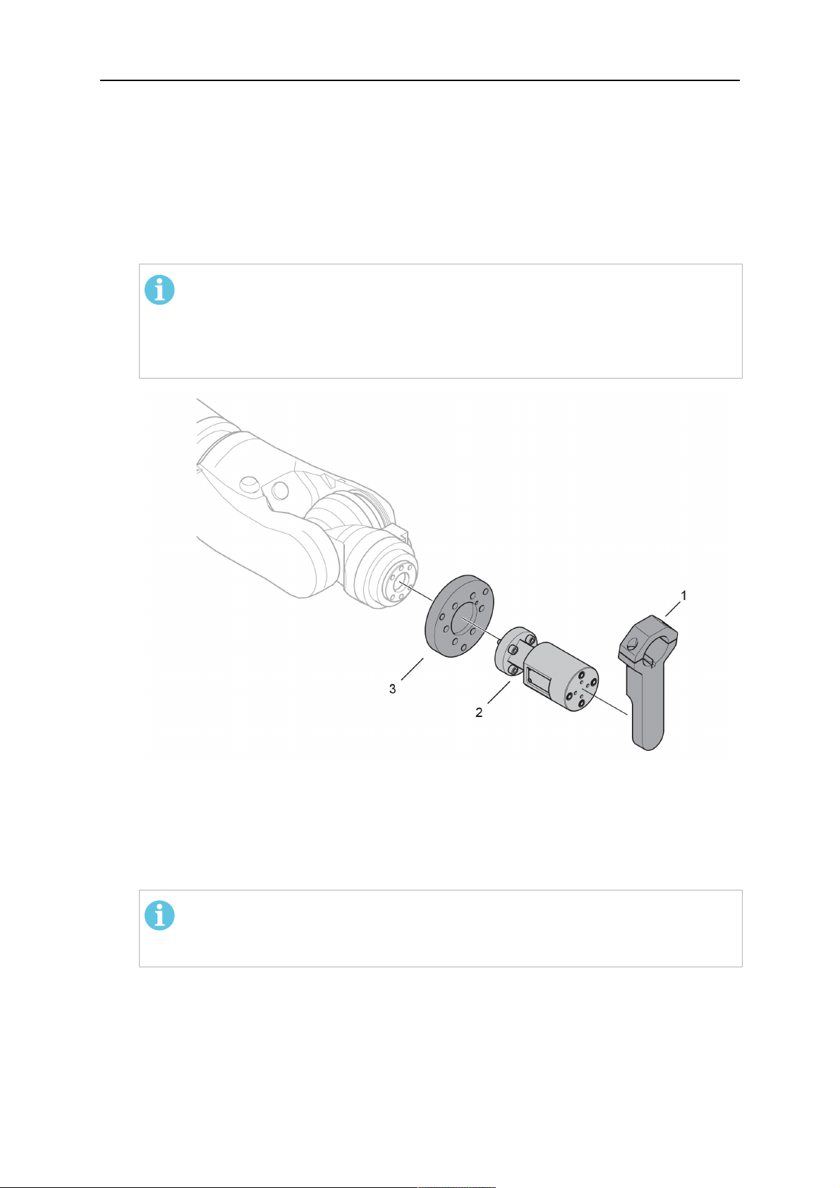
4.3.2.1 RTKSC-2 G/W nosač plamenika sa sigurnosnim mehanizmom
StavkaOpis Funkcija
1 Potporanj vrata plamenika Sučelje Aristo RT plamenika
2 RTKSC-2 poklopac Sklop sa kabelima i sučeljem plamenika
3 Gumene čizme Zaštita za sigurnosni mehanizam
0463 373 101
- 16 -
© ESAB AB 2018

4 TEHNIČKI PODACI
StavkaOpis Funkcija
4 RTKSC-2 glavno tijelo Dozvoljeni mehanički otklon tijekom kolizije
5 Adapterska prirubnica Izolacijsko sučelje za zglob robota (mora odgovarati
određenom robotu)
6 Usmjeravajući zatik Za precizno poravnanje s adapterskom prirubnicom
7 Priključak za upravljački kabel Električno povezivanje signala kolizije i funkcije
osjetne mlaznice
8 Mikrosklopka Senzor za otkrivanje kolizije
4.3.2.2 RTFLC-2 G/W nesavitljivi nosač plamenika
StavkaOpis Funkcija
1 Potporanj vrata plamenika Aristo RT sučelje plamenika
2 RTFLC-2 poklopac Sklop sa kabelima i sučeljem plamenika
3 RTFLC-2 glavno tijelo Dozvoljeni mehanički otklon tijekom kolizije
4 Usmjeravajući zatik Za precizno poravnanje s adapterskom prirubnicom
5 Adapterska prirubnica Izolacijsko sučelje za zglob robota (mora odgovarati
određenom robotu)
6 Priključak za upravljački kabel
(3 polni)
0463 373 101
Električno povezivanje za funkciju osjetne mlaznice
(ako je dostupna)
- 17 -
© ESAB AB 2018

4 TEHNIČKI PODACI
4.4 Adapterske prirubnice
Odaberite adaptersku prirubnicu potrebnu za instalaciju na robotsku ruku ovisno o vrsti
robota. Adapterska prirubnica za sve vrste odgovarajućih standardnih i sustava sa šupljim
zglobovima sustava koji su dostupni, pogledajte popis rezervnih dijelova.
4.5 Kabelski sklopovi
Kabelski sklop ostvaruje vezu s uređajem za dopremanje žice, a dostupne verzije uglavnom
ovise o sustavu dizajna i sredstva za hlađenje (plin ili voda), pogledajte popis rezervnih
dijelova.
Nazivne vrijednosti valjane su za kabele duljine od 1 do 5 m.
Duljina kabela Infiniturn Helix
Vrijednost (ciklus od
10 min.)
Hlađenje plinom
(miješani plin)
Vrijednost (ciklus od
10 min.)
Maks. 500 A / 60 %
radnog ciklusa
Maks. 350 A / 100 %
radnog ciklusa
Maks. 600 A / 100 %
radnog ciklusa
Maks. 400 A / 60 %
radnog ciklusa
Maks. 320 A / 100 %
radnog ciklusa
Maks. 550 A / 100 %
radnog ciklusa
Vodom hlađeni
Rotacijski raspon Ograničena
Neograničeni okret ± 270° od neutralnog
mogućnost rotacije
Težina
Plinom hlađeni
Težina
Vodom hlađeni
Duljina 1,2 m:
2,35 kg
Duljina 1.2 m:
2,35 kg
Duljina 1,0 m:
2,0 kg
Duljina 1.0 m:
2,0 kg
4.5.1 Vrat plamenika za standardni RT sustav
Maks. 400 A / 60 %
radnog ciklusa
Maks. 320 A / 100 %
radnog ciklusa
Maks. 550 A / 100 %
radnog ciklusa
položaja
Duljina 1.0 m:
2,0 kg
Duljina 1.0 m:
2,0 kg
0463 373 101
- 18 -
© ESAB AB 2018

4 TEHNIČKI PODACI
Zatici Burndy priključka
A. Osjetljivost na dodir
kontaktnog vrha
C. Senzor kolizije
F. 0V
G. + Napon motora
H. - Napon motora
D. Senzor kolizije
E. Postupno dopremanje
StavkaOpis Funkcija
1 Prirubnica potpornja vrata
Sučelje plamenika
prirubnice
2 Zaštitni poklopac Štiti kabelski sklop od oštećenja
3 Burndy priključak, 12 polni Električni priključak između sigurnosnog
isključivanja i dopremanja žice
4 Upravljački kabel Za KS-2 (sigurnosno isključivanje i gumb za
pokretanje)
5 EURO priključak Povezivanje dopremljene žice
6 Ispušna cijev (crni čep) Za čišćenje plamenika komprimiranim zrakom
nakon ciklusa čišćenja
7 Dovod vode (plavi čep)
8 Povrat vode (crveni čep)
9 Utikač upravljačkog kabela za
sigurnosni mehanizam
1)
Sustav plamenika hlađen samo vodom
Dovod vode za hlađenje plamenika
Povrat vruće vode iz plamenika
Električni priključak s RTKS-2 sigurnosnim
signalom i funkcijom osjetne mlaznice
1)
1)
4.5.2 Kabelski sklop za sustav šupljih zglobova
Infiniturn kabelski sklop omogućava neograničenu rotaciju plamenika u oba smjera.
Istodobno se prenose tekućina za hlađenje, zaštitni plin, ispušni zrak, izvor napajanja i signal
sigurnosnog mehanizma.
Helix kabelski sklop namijenjen je za rotaciju od ±270° iz neutralnog položaja. Može se rabiti
za vrste zavarivanja koje ne zahtijevaju beskrajnu rotaciju.
Infiniturn kabelski sklopovi dostupni su u verziji s plinskim i vodenim hlađenjem. Helix
kabelski sklopovi mogu se jednako rabiti za plinski ili vodeni sustav hlađenja.
NAPOMENA!
Plinom hlađeni vrat plamenika kod Helix kabelskog sklopa nikada nemojte
povezivati na vrat plamenika vodom hlađenog sustava.
0463 373 101
- 19 -
© ESAB AB 2018

4 TEHNIČKI PODACI
StavkaOpis Funkcija
1 Prirubnica Sučelje nosača plamenika RTKSC-2 / RTFLC-2
2 Usmjeravajući zatik Osigurava ispravno okretanje prilikom spajanja
3 Utikač upravljačkog kabela Električni priključak s RTKSC-2 sigurnosnim
signalom i funkcijom osjetne mlaznice (ako je
dostupna)
4 EURO priključak Povezivanje dopremljene žice
5 Upravljački kabel Električni priključak za sigurnosni signal (od
RTKSC-2) i za funkciju osjetne mlaznice (osjetne
mlaznice standardne su za Helix, ali ne i za
Infiniturn)
6 Povrat vode (crveni čep) Povrat vruće vode iz plamenika
7 Dovod vode (plavi čep) Dovod vode za hlađenje plamenika
8 Ispušna cijev (crni čep) Za čišćenje plamenika komprimiranim zrakom
nakon varenja
9 Spajanje medija Beskonačno rotirajući priključak s medijem prijenosa
10 Zaštitni poklopac Štiti kabelski sklop od oštećenja
0463 373 101
- 20 -
© ESAB AB 2018

5 INSTALLATION
5 INSTALLATION
UPOZORENJE!
For your own safety, make sure that the robot is either in standby or power-less
state before doing maintenance work in the moving radius of the robot.
Follow the assembly instructions exactly. Pay attention during assembly that the cables are
not damaged. Damaged cables can lead to a short circuit, which may damage the electronics
of the robot or the welding torch.
Use only original ESAB components that have been specially developed for this purpose.
Only then the correct functioning of the whole welding torch system can be guaranteed.
5.1 RTKS-2 standard arm installation
5.1.1 RTKS-2 safety-off mechanism
1. Dismount the insulation flange (10) from the RTKS-2 (11) by removing the screws
(12).
2. Position the insulation flange (10) with the index pin on the robot arm and fix it with the
screws (20) included.
The insulation flange (10) is directly compatible with robots with tool flange according
to DIN ISO 9409-1-A40 (diameter 40mm, 4×M6). If the insulation flange (10) does
not fit, use an adapter flange (21).
NAPOMENA!
Ensure that the index pin is located correctly. The maximum torque of 1.2Nm
(10.5in.lb) must be observed for the fastening of the adapter flange screws.
Prevent self-loosening of the screws by using suitable thread locking
measures.
3. Mount the RTKS-2 the back on the insulation flange (10).
0463 373 101
- 21 -
© ESAB AB 2018

5 INSTALLATION
4. Position the mount on the RTKS-2 and carefully insert the cylindrical pins (14) into the
holes provided. Take the position of the torch into account. Two mounting positions
may be potentially possible.
5. Screw the mount evenly using the enclosed cylinder screws with hexagon socket (12).
NAPOMENA!
The maximum tightening torque for the cylinder screw (5) is 6Nm (53in.lb)
and the property class category is 8.8.
12 - Cylinder screw with hexagon socket
M6DIN912 (length of the screw depending
on the torch mount)
14 - Cylindrical pins Ø4×20
5.1.1.1 Torch installation with adjustable mount
Torch mounts with a central clamping assembly can only be fastened on the journal of the
mounting flange. For this, the mounting flange must be fastened first.
1. If applicable, carefully press the cylindrical pins (1) into the corresponding holes in the
mounting flange. The pins should protrude by approximately 5 mm (0.2 in.).
2. Position the mount on the safety-off mechanism RTKS-2 and carefully insert the
cylindrical pins (1) into the holes provided. In doing so, take the later position of the
torch into account. Two mounting positions may be potentially possible.
3. Then screw down the mounting flange evenly using the enclosed cylinder screws with
hexagon socket (2).
NAPOMENA!
The maximum tightening torque for the cylinder screw (2) is 7.1 Nm (62.8
in.lb) and the property class category is 8.8.
0463 373 101
- 22 -
© ESAB AB 2018

5 INSTALLATION
4. Unscrew the axial cylinder screw with hexagon socket (4) out of the mounting flange
together with the washer (3).
1 - Cylindrical pins Ø4×14 3 - Washer Ø9 mm
2 - Cylinder screw with hexagon socket
M6×16
4 - Axial cylinder screw with hexagon
socket M8×16
5. Place the torch mount (5) onto the journal (6) of the mounting flange, paying attention
while doing so to the exact alignment of the feather key (7) and the corresponding
groove (7a).
6. Insert the clamping mandrel (8) into the lateral hole (see illustration) and position it so
that the mating surfaces (9a) of the clamping mandrel rest on the mating surface (9) of
the journal.
0463 373 101
- 23 -
© ESAB AB 2018

5 INSTALLATION
7. Fix the clamping mandrel from the opposite side using the M6 cylinder screw with
hexagon socket (10) and the Ø22 mm washer (11).
8. Screw the axial cylinder screw (4) with the Ø9 mm washer (3) into the mounting flange
and tighten firmly.
3 - Washer Ø9 mm 8 - Clamping mandrel
4 - Axial cylinder screw with hexagon
9 - Mating surface of mounting flange
socket M8×16
5 - Torch mount 9a - Mating surfaces of clamping mandrel
6 - Mounting flange journal 10 - Cylinder screw with hexagon socket
M6×30
7 Feather key 11 - Washer Ø22×6.4 mm
7a - Groove for feather key
5.1.2 Standard arm cable assembly for KS-2 and FL-2
The cable assembly must be aligned to the intended use in length and design. The type of
cooling for the torch and the cable assembly must be the same (either gas or water cooled
respectively). In order to prevent damage to the torch system and other components, it is
imperative to observe the following instructions.
0463 373 101
- 24 -
© ESAB AB 2018

5 INSTALLATION
OPREZ!
• Coordinate the length and design of the cable assembly to suit the range of
action of the robot.
• Do not bend, compress or overstretch the cable assembly.
• Fix the cable assembly such that is can be moved freely and cannot become
entangled.
• Any additional holding devices possibly installed, for example a balancer,
must not crush or bend the cable assembly.
• Extreme turning movements must be avoided in which the cable assembly
may become twisted.
• Chafing on the robot or other objects must be excluded.
1. Unscrew the cylinder screws (1) and lift off the top section (2) of the torch mount.
2. Insert the feather key (4) into the recess of the neck support flange (3) from below.
3. Align the neck support flange (3) including the feather key (4) to the groove (5) of the
torch mount and push into the groove right up to the stop of the flange.
4. Hold the cable assembly in this position and simultaneously place the top section (2)
back onto the torch mount. First screw both cylinder screws (1) loosely in to about the
same length, then tighten alternately. The top section (2) of the mount should have an
even gap to the bottom section.
The front part of the cable assembly is directly clamped into the torch mount (see
illustration below).
1 - Cylinder screws 4 - Feather key
2 - Torch mount top section 5 - Groove for feather key
3 - Neck support flange
5.1.3 RTKS-2 wire feeder connection
In order to be able to create the connection, the cable assembly must be mounted as
described in the "Installing the cable assembly" section and equipped following "Installing the
wire guide" section. Only then can the central and media connection take place. Proceed as
described below:
0463 373 101
- 25 -
© ESAB AB 2018

5 INSTALLATION
1. Connect the central connector of the cable assembly (2) to the wire feeder cabinet
socket. Tighten the central connector sleeve nut fingertight. Do not use tools.
1 - Burndy Connector 4 - Return of heated water (red cap)
2 - EURO central connector 5 - Return of heated water (red cap)
3 - Air blow-out 6 - Main Wire feeder
2. For water cooled systems. Connect the water hoses to the cooling circuit. The end of
the hose marked blue (4) is connected to the water outlet, and the end marked red (5)
is connected to the water return.
3. Connect the blow-out line (3) to the corresponding connection of the feeder.
4. Connect the Burndy Connector to the wire feeder. (1) to the feeder. See section
"Electrical connections".
NAPOMENA!
All hoses and the control line must be installed so they can not bend or get
damaged!
5.1.4 RTKS-2 electrical connections
5.1.4.1 RTKS-2 safety-off mechanism connection
The switch for the safety-off functionality RTKS-2 is connected through the control cable,
see (3) in the illustration below. This connects to the RTKS-2 unit via the 4-pole plug (4) that
contains circuits for the push-button (6) and the safety-off signal (7).
If a collision is detected, the control circuit for the safety-off signal (7), which is normally
closed, will be interrupted.
Rating of the control circuit: max. 48 V / 1 A
0463 373 101
- 26 -
© ESAB AB 2018

5 INSTALLATION
2 - Burndy connector 5 - RTKS-2 connector for control cable plug
4 - Control cable plug
Zatici Burndy priključka
A. Osjetljivost na dodir
kontaktnog vrha
C. Senzor kolizije
F. 0V
G. + Napon motora
H. - Napon motora
D. Senzor kolizije
E. Postupno dopremanje
If the robot control provides a control circuit for nozzle sense functionality, the connection is
accomplished with a 1-wire connection.
Rating of the control circuit: max 50 V / 5 A.
OPASNOST!
If the nozzle sense function is not being used, the open end of the control cable on
the power source connection side must be properly isolated in order to avoid short
circuits. During certain problems on the torch head, the full welding potential may be
present on this cable.
OPREZ!
After detection of contact (gas nozzle on work piece), quickly reduce or cut off the
maximum current in the nozzle sense circuit in order to avoid overloading of the
system.
Allowed load max. 1 minute at the rated nominal current.
5.1.5 RTKS-2 Torch installation
Continue according to section "Torch installation".
0463 373 101
- 27 -
© ESAB AB 2018
5 INSTALLATION
5.2 RTFL-2 standard arm installation
5.2.1 RTFL-2 rigid mount
1. Position the RT FL-2 (2) with the index pin on the robot arm and fix it with the hexagon
socket screw included.
The FL-2 is directly compatible with robots with tool flange according to DIN ISO
9409-1-A40 (diameter 40mm, 4×M6). If the rigid mount does not fit, use an adapter
flange (3).
NAPOMENA!
Ensure that the index pin is located correctly. The maximum torque of 1.2Nm
(10.5in.lb) must be observed for the fastening of the adapter flange screws.
Prevent self-loosening of the screws by using suitable thread locking
measures.
2. Install torch mount (1). Only torch mounts having a hole pattern equivalent with the
mounting surface may be attached. If necessary, carefully press the cylindrical pins (4)
into the corresponding holes in the bracket. The pins should protrude by
approximately 5mm (0.2in.). Position the torch mount on the RTFL-2 (2) and
carefully insert the cylindrical pins (4) into the holes provided. Take the position of the
torch into account. Two mounting positions may be potentially possible.
3. Screw the mount evenly using the enclosed cylinder screws with hexagon socket (5).
NAPOMENA!
The maximum tightening torque for the cylinder screw (5) is 6Nm (53in.lb)
and the property class category is 8.8.
0463 373 101
- 28 -
© ESAB AB 2018

5 INSTALLATION
4 - Cylindrical pins Ø4×20
5 - Cylinder screw with hexagon socket M6
DIN 912 (length of the screw depending on
the torch mount)
Side view
Torch installation with adjustable mount
Torch mounts with a central clamping assembly can only be fastened on the journal of the
mounting flange. For this, the mounting flange must be fastened first.
1. If applicable, carefully press the cylindrical pins (1) into the corresponding holes in the
mounting flange. Avoid the formation of burrs. The pins should protrude by
approximately 5 mm (0.2 in.).
2. Position the mount on the RTFL-2 and carefully insert the cylindrical pins (1) into the
holes provided. In doing so, take the later position of the torch into account. Two
mounting positions may be potentially possible.
3. Then screw down the mounting flange evenly using the enclosed cylinder screws with
hexagon socket (2).
NAPOMENA!
The maximum tightening torque for the cylinder screw (2) is 7.1 Nm (62.8
in.lb) and the property class category is 8.8.
4. Unscrew the axial cylinder screw with hexagon socket (4) out of the mounting flange
together with the washer (3).
1 - Cylindrical pins Ø4×14 3 - Washer Ø9 mm
2 - Cylinder screw with hexagon socket
M6×16
4 - Axial cylinder screw with hexagon
socket M8×16
5. Place the torch mount (5) onto the journal (6) of the mounting flange, paying attention
while doing so to the exact alignment of the feather key (7) and the corresponding
groove (7a).
0463 373 101
- 29 -
© ESAB AB 2018

5 INSTALLATION
6. Insert the clamping mandrel (8) into the lateral hole (see illustration) and position it so
that the mating surfaces (9a) of the clamping mandrel rest on the mating surface (9) of
the journal.
7. Fix the clamping mandrel from the opposite side using the M6 cylinder screw with
hexagon socket (10) and the Ø22 mm washer (11).
8. Screw the axial cylinder screw (4) with the Ø9 mm washer (3) into the mounting flange
and tighten firmly.
3 - Washer Ø9 mm 8 - Clamping mandrel
4 - Axial cylinder screw with hexagon
9 - Mating surface of mounting flange
socket M8×16
5 - Torch mount 9a - Mating surfaces of clamping mandrel
6 - Mounting flange journal 10 - Cylinder screw with hexagon socket
M6×30
7 - Feather key 11 - Washer Ø22×6.4 mm
7a - Groove for feather key
5.2.2 RTFL-2 torch installation
Continue according to section "Torch installation".
5.3 RTKSC-2 hollow wrist system installation
5.3.1 RTKSC-2 mount with safety off mechanism
OPREZ!
For hollow wrist systems make sure that the clear space around the robot is at least
Ø45 mm (1.8 in.) around the wrist and 50 mm (2.0 in.) near the wire feeder.
0463 373 101
- 30 -
© ESAB AB 2018

5 INSTALLATION
1. Remove the three screws (2) from the front cover (3) of the torch mount and carefully
pull the cover off the RTKSC-2 main body (5). Take care not to damage the micro
switches installed inside the assembly.
1 - Hexagon wrench 4 mm 4 - Rubber boot
2 - 3× M5×12 screws 5 - RT KSC-2 main body
3 - RT KSC-2 front cover
1. Pull off the rubber boot (4) from the RTKSC-2 main body (5) to the front.
2. Now position the RTKSC-2 main body (5) on the adapter flange (7) so that the index
pin is correctly seated. Attach with the screws (6) enclosed.
3. Reinstall the rubber boot (4) on the RTKSC-2 main body (5) and make sure it is
correctly located in the grooves on the front and back flange.
4. Istall the adapter flange (7) on the robot.
Fastening torque max. 2.2 Nm (19.5 in.lb).
1 - Hexagon wrench 4 mm 3 - 3× M5×12 hexagon socket screws
2 - Rubber boot 4 - Adapter flange
5.3.2 Mounting the cable assembly
NAPOMENA!
In order to adjust the wire feeder position to the cable assembly length, it must be
mounted on an adjustable support with a possible movement of ±2-3cm (±1in.) to
the back and to the front. The length of the cable assembly must be determined
from the centred mounting position of the wire feeder.
1. Move the robot arm into a completely straight position, see illustration below. Make
sure that (1) axis 6 (rotation around the torch axis) is in 0° position.
2. Move the feeder (3) completely to the back in order to create space for inserting the
cable assembly. If it is not possible to move the feeder sufficiently, it should be
removed from the robot.
0463 373 101
- 31 -
© ESAB AB 2018

5 INSTALLATION
3. Insert the cable assembly with the coupling (2) first into the robot arm and feed it
through the robot wrist.
4. The feeder should only be installed again after the correct mounting position with
respect to the cable length has been determined. (See section "Installing the cable
assembly").
OPREZ!
Axis 6 must be in 0° position.
5.3.2.1 RTKSC-2 feeder cabinet connections
When installed for the first time, the position of the wire feeder cabinet must be adjusted to
the length of the cable assembly. First, the robot arm must be fully extended (straight).
OPREZ!
As long as the correct position of the feeder corresponding to the length of the cable
assembly has not been determined, be careful when moving the robot arm and
avoid overstretching the cable. It is helpful to loosen the positioning screws of the
feeder before moving the robot arm to allow the feeder to follow the cable assembly.
0463 373 101
- 32 -
© ESAB AB 2018

5 INSTALLATION
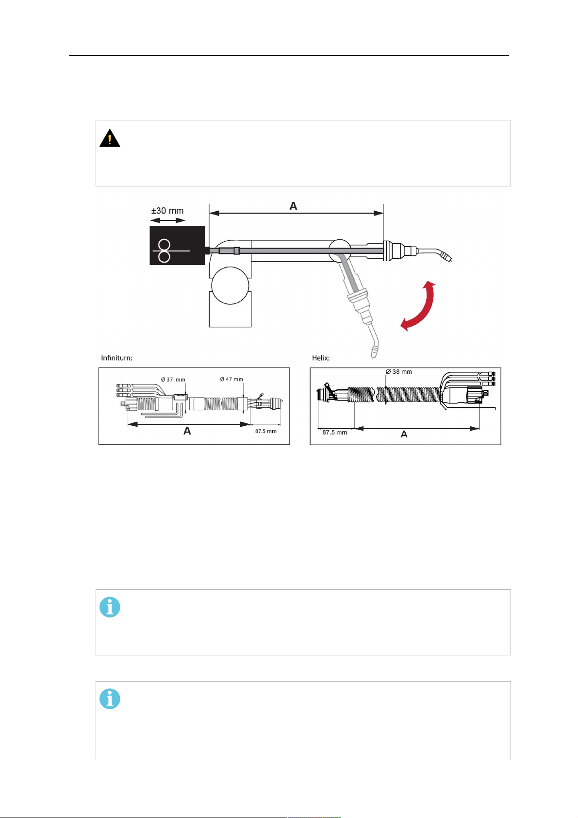
1. Loosen the sliding mechanism of the wire feeder and connect the cable assembly.
2. Now adjust the position of the wire feeder to suit the length of the Infiniturn or Helix
cable, as indicated with "A" in the illustration below.
OPREZ!
When adjusting the position of the feeder cabinet, make sure that the cable
assembly is not under stress when the robot arm is in stretched-out position.
It is normal for the cable assembly to sag slightly, it should never be taut.
3. Before securing the wire feeder in its permanent position, ensure that the Euro
connectors are tightly connected. Then turn the torch mount down and up again
(rotating on the axis 5), in order not to tighten the cable assembly too much against
the feeder (see illustration above). Once this is done, tighten the feeder in that
position.
4. For water cooled systems, connect the water lines to the cooling circuit. See section
"Cable assemblies for hollow wrist systems" in the TECHNICAL DATA chapter for
indications.
The hose with the blue rubber cap is for cooling water to the torch, the hose with the
red rubber cap returns the heated water. Make sure the hoses will not kink or get
otherwise blocked.
NAPOMENA!
A Helix cable assembly used for a gas cooled system must not be connected
to a cooling circuit. As the water connections are not needed, they may be cut
off.
5. Connect the blow-out hose (black rubber cap) to the corresponding outlet of the wire
feeder.
NAPOMENA!
If the blow-out function is not used, the blow-out hose must be sealed with the
rubber cap enclosed. With Infiniturn systems, the blow-out air must be
supplied to the corresponding connection hose, if it is not permitted to connect
blow-out air to the shield gas connection!
6. Install the necessary plug on the control cable and connect it to the safety off circuit
interface of the wire feeder (see section "Electrical connections").
0463 373 101
- 33 -
© ESAB AB 2018

5 INSTALLATION
5.3.3 RTKSC-2 cable assembly
The cable assembly must be aligned to the intended use in length and design. The type of
cooling for the torch and the cable assembly must be the same (either gas or water cooled
respectively). In order to prevent damage to the torch system and other components, it is
imperative to observe the following instructions.
OPREZ!
• Coordinate the length and design of the cable assembly to suit the range of
action of the robot.
• Do not bend, compress or overstretch the cable assembly.
• Fix the cable assembly such that is can be moved freely and cannot become
entangled.
• Any additional holding devices possibly installed, for example a balancer,
must not crush or bend the cable assembly.
• Extreme turning movements must be avoided in which the cable assembly
may become twisted.
• Chafing on the robot or other objects must be excluded.
5.3.3.1 RTKSC-2 cable assembly installation
NAPOMENA!
For some robots, it may be possible to deviate from this order, and first connect the
cable assembly to the RTKSC-2, then thread the cable from the front through the
robot arm. If in doubt, follow the suggested order.
1. Loosen the three screws (7) with the associated washers and remove them from the
RTKSC-2 cover (1). See illustration below.
2. Install the supplied O-rings (4) into the grooves in the cover (1).
3. Pull the cable assembly approximately 15 cm (6 in.) from the main body (3).
0463 373 101
- 34 -
© ESAB AB 2018

5 INSTALLATION
4. Insert the coupling (2) into the socket of the cover (1) as shown. Align the index pin (6)
with the index hole (5) in the main body and insert completely.
NAPOMENA!
Make sure that the position of the O-rings are not shifted by the index pin
during the assembly.
1 - RTKSC-2 cover 5 - Index hole
2 - Coupling 6 - Index pin
3 - RTKSC-2 main body 7 - 3× M5×35 screws
4 - 3× O-ring for water cooled systems 11 - Control cable connector
5. Insert the three screws (7) with the associated washers (8) and tighten gently with the
enclosed hexagonal wrench, see below illustration.
Fastening torque approximately 2 Nm (18 in.lb).
0463 373 101
- 35 -
© ESAB AB 2018

5 INSTALLATION
6. If present, insert the control cable plug (10) into the connector (11) and make sure it is
firmly seated.
7 - 3× M5×35 screw 11 - Control cable connector
8 - Washer 12 - 2× Micro switch
10 - Control cable plug 13 - Index pin
7. Gently push back the cable assembly into the robot arm and carefully seat the
RTKSC-2 cover (1) in place. Observe the index pin (13) to be in the correct position.
Make sure the two micro switches (12) are not damaged if present.
8. Insert the three M5 screws (14) and tighten without excessive force.
13. Index pin
14. 3× M5×12 screws
0463 373 101
- 36 -
© ESAB AB 2018

5 INSTALLATION
5.3.3.2 RTKSC-2 electrical connections
NAPOMENA!
After connecting the control cable, secure the cable in order to protect it from getting
caught while the robot is moving.
Usually, the control cable will be directly connected to the wire feeder. See the
manufacturer's documentation for details. The link to the robot control is then
implemented via the power source controller.
RTKSC-2 safety-off mechanism connection
The switch for the safety-off functionality RTKSC-2 is connected through the control cable,
see (3) in the illustration below. This connects to the RTKSC-2 unit via the control cable plug
(1).
The safety-off signal requires a 2-wire connection (black/black) to the safety-off circuit in the
robot control (5).
If a collision is detected, the control circuit (normally closed) will be interrupted (4).
Rating of the control circuit: max. 48 V / 1 A.
1 - Control cable plug 3 - Burndy connector VVV
2 - EURO central connector
Zatici Burndy priključka
A. Osjetljivost na dodir
kontaktnog vrha
C. Senzor kolizije
F. 0V
G. + Napon motora
H. - Napon motora
D. Senzor kolizije
E. Postupno dopremanje
RTKSC-2 nozzle sense function connection
If the robot control provides a control circuit for nozzle sense functionality.
The connection is accomplished with a 2-wire connection (black/black) to the nozzle sense
circuit in the robot control (5), see illustration below.
0463 373 101
- 37 -
© ESAB AB 2018

5 INSTALLATION
Usually, the control cable will be directly connected to the wire feeder. See the
manufacturer's documentation for details. The link to the robot control is then implemented
via the power source robot interface.
Rating of the control circuit: max. 50 V / 5 A.
OPASNOST!
If the nozzle sense function is not being used, the open end of the control cable on
the power source connection side must be properly isolated in order to avoid short
circuits. During certain problems on the torch head, the full welding potential may be
present on this cable.
OPREZ!
After detection of contact (gas nozzle on work piece), quickly reduce or cut off the
maximum current in the nozzle sense circuit in order to avoid overloading of the
system.
Allowed load max. 1 minute at the rated nominal current.
1 - Control cable plug 3 - Control cable
2 - EURO central connector
5.3.4 RTKSC-2 torch installation
Continue according to section "Torch installation".
0463 373 101
- 38 -
© ESAB AB 2018

5 INSTALLATION
5.4 RTFLC-2 installation
5.4.1 RTFLC-2 mount
1. Remove the three M5 screws (2) from the front cover (3) of the RT FLC-2 torch mount
and carefully pull the cover off the main body (4).
1 - Hexagon wrench 4 mm 3 - RT FLC-2 front cover
2 - 3× M5×12 screws 4 - RT FLC-2 main body
2. Now position the RT FLC-2 main body (4) on the adapter flange (6) so that the index
pin is correctly seated. Attach with the screws (5) enclosed
Fastening torque max. 2.2 Nm (19.5 in.lb).
1 - Hexagon wrench 4 mm 5 - 3× M5×12 hexagon socket screws
4 - RT FLC-2 main body 6 - Adapter flange
5.4.2 RTFLC-2 wire feeder connection
5.4.2.1 Feeding through the robot arm
NAPOMENA!
In order to adjust the wire feeder position to the cable assembly length, it must be
mounted on an adjustable support with a possible movement of ± 2-3 cm (± 1 in.) to
the back and to the front. The length of the cable assembly must be determined
from the centred mounting position of the wire feeder.
0463 373 101
- 39 -
© ESAB AB 2018

5 INSTALLATION
1. Move the robot arm into a completely straight position, see illustration below. Make
sure that (1) axis 6 (rotation around the torch axis) is in 0° position.
2. Move the feeder (3) completely to the back in order to create space for inserting the
cable assembly. If it is not possible to move the feeder sufficiently, it should be
removed from the robot.
3. Insert the cable assembly with the coupling (2) first into the robot arm and feed it
through the robot wrist.
4. The feeder should only be installed again after the correct mounting position with
respect to the cable length has been determined. (See section "Installing the cable
assembly").
OPREZ!
Important! Axis 6 must be in 0° position.
5.4.2.2 RTFLC-2 feeder cabinet connections
When installed for the first time, the position of the wire feeder cabinet must be adjusted to
the length of the cable assembly. First, the robot arm must be fully extended (straight).
OPREZ!
As long as the correct position of the feeder corresponding to the length of the cable
assembly has not been determined, be careful when moving the robot arm and
avoid overstretching the cable. It is helpful to loosen the positioning screws of the
feeder before moving the robot arm to allow the feeder to follow the cable assembly.
0463 373 101
- 40 -
© ESAB AB 2018
5 INSTALLATION
1. Loosen the sliding mechanism of the wire feeder and connect the cable assembly.
Refer to the instruction of the feeder manufacturer.
2. Now adjust the position of the wire feeder to suit the length of the Infiniturn or Helix
cable, as indicated with "A" in the illustration below.
OPREZ!
When adjusting the position of the feeder cabinet, make sure that the cable
assembly is not under stress when the robot arm is in stretched-out position.
It is normal for the cable assembly to sag slightly, it should never be taut.
3. Before securing the wire feeder in its permanent position, ensure that the Euro
connections are tightly connected. Then turn the torch mount down and up again
(rotating on the axis 5), in order not to tighten the cable assembly too much against
the feeder (see illustration above). Once this is done, tighten the feeder in that
position.
4. For water cooled systems, connect the water lines to the cooling circuit. See section
"Cable assemblies for hollow wrist systems" in the TECHNICAL DATA chapter for
indications.
The hose with the blue rubber cap is for cooling water to the torch, the hose with the
red rubber cap returns the heated water. Make sure the hoses will not kink or get
otherwise blocked.
NAPOMENA!
A Helix cable assembly used for a gas cooled system must not be connected
to a cooling circuit. As the water connections are not needed, they may be cut
off.
5. Connect the blow-out hose (black rubber cap) to the corresponding outlet of the wire
feeder.
NAPOMENA!
If the blow-out function is not used, the blow-out hose must be sealed with the
rubber cap enclosed. With Infiniturn systems, the blow-out air must be
supplied to the corresponding connection hose, if it is not permitted to connect
blow-out air to the shield gas connection!
0463 373 101
- 41 -
© ESAB AB 2018

5 INSTALLATION
6. Install the necessary plug on the control cable and connect it to the safety off circuit
interface of the wire feeder (see section "Electrical connections").
5.4.3 RTFLC-2 cable assembly
The cable assembly must be aligned to the intended use in length and design. The type of
cooling for the torch and the cable assembly must be the same (either gas or water cooled
respectively). In order to prevent damage to the torch system and other components, it is
imperative to observe the following instructions.
OPREZ!
• Coordinate the length and design of the cable assembly to suit the range of
action of the robot.
• Do not bend, compress or overstretch the cable assembly.
• Fix the cable assembly such that is can be moved freely and cannot become
entangled.
• Any additional holding devices possibly installed, for example a balancer,
must not crush or bend the cable assembly.
• Extreme turning movements must be avoided in which the cable assembly
may become twisted.
• Chafing on the robot or other objects must be excluded.
5.4.3.1 RTFLC-2 cable assembly installation
In a hollow wrist system the recommended order of installation is to feed the cable assembly
through the robot arm before connecting the cables to the torch mount.
When the cable assembly is correctly installed in the hollow wrist, continue the installation
according to the procedure described below.
NAPOMENA!
For some robots, it may be possible to deviate from this order, and first connect the
cable assembly to the RTKSC-2 and RTFLC-2, then thread the cable from the front
through the robot arm. If in doubt, follow the suggested order.
1. Loosen the three screws (7) with the associated washers and remove them from the
RTFLC-2 cover (1). See illustration below.
2. Install the supplied O-rings (4) into the grooves in the cover (1). For gas cooled
systems, only one O-ring (4a) is needed, for water cooled systems all three O-rings
are needed.
3. Pull the cable assembly approximately 15 cm (6 in.) from the main body (3).
0463 373 101
- 42 -
© ESAB AB 2018

5 INSTALLATION
4. Insert the coupling (2) into the socket of the cover (1) as shown. Align the index pin (6)
with the index hole (5) in the main body and insert completely.
NAPOMENA!
Take great care that the position of the O-rings is not shifted by the index pin
during the assembly.
1 - RT FLC-2 cover 5 - Index hole
2 - Coupling 6 - Index pin
3 - RT FLC-2 main body 7 - 3× M5×35 screws
4 - 3× O-ring for water cooled systems 11 - Control cable connector
5. Insert the three screws (7) with the associated washers (8) and tighten gently with the
enclosed hexagonal wrench, see below illustration.
Fastening torque approximately 2 Nm (18 in.lb).
0463 373 101
- 43 -
© ESAB AB 2018

5 INSTALLATION
6. If present insert the control cable plug (10) into the connector (11) and make sure it is
firmly seated.
7 - 3× M5×35 screw 11 - Control cable connector
8 - Washer 12 - 2× Micro switch
10 - Control cable plug 13 - Index pin
7. Gently push back the cable assembly into the robot arm and carefully seat the
RTFLC-2 cover (1) in place. Observe the index pin (13) to be in the correct position.
Make sure the two micro switches (12) are not damaged if present.
8. Insert the three M5 screws (14) and tighten without excessive force.
13 - Index pin 14 - 3x M5x12 screws
0463 373 101
- 44 -
© ESAB AB 2018

5 INSTALLATION
5.4.4 RTFLC-2 electrical connections
NAPOMENA!
After connecting the control cable, secure the cable in order to protect it from getting
caught while the robot is moving.
Usually, the control cable will be directly connected to the wire feeder. See the
documentation of the manufacturer for details. The link to the robot control is then
implemented via the power source controller.
5.4.4.1 RTFLC-2 hollow wrist system with Infiniturn cable assembly
Connecting the nozzle sense function
If the robot control provides a control circuit for nozzle sense functionality.
The connection is accomplished with a 2-wire connection (black/black) to the nozzle sense
circuit in the robot control (5), see illustration below.
Usually, the control cable will be directly connected to the wire feeder. See the
manufacturer's documentation for details. The link to the robot control is then implemented
via the power source robot interface.
Rating of the control circuit: max. 50 V / 5 A.
OPASNOST!
If the nozzle sense function is not being used, the open end of the control cable on
the power source connection side must be properly isolated in order to avoid short
circuits. During certain problems on the torch head, the full welding potential may be
present on this cable.
OPREZ!
After detection of contact (gas nozzle on work piece), quickly reduce or cut off the
maximum current in the nozzle sense circuit in order to avoid overloading of the
system.
Allowed load max. 1 minute at the rated nominal current.
1 - Control cable plug 3 - Control cable
2 - EURO central connector
0463 373 101
- 45 -
© ESAB AB 2018

5 INSTALLATION
5.4.4.2 RTFLC-2 hollow wrist system with Helix cable assembly
Connecting the nozzle sense function
If the robot control provides a control circuit for nozzle sense functionality.
The connection is accomplished with a 1-wire connection (green) to the nozzle sense circuit
in the robot control (5), see illustration below.
Usually, the control cable will be directly connected to the wire feeder. See the
manufacturer's documentation for details. The link to the robot control is then implemented
via the power source robot interface.
Rating of the control circuit: max. 50 V / 5 A.
OPASNOST!
If the nozzle sense function is not being used, the open end of the control cable on
the power source connection side must be properly isolated in order to avoid short
circuits. During certain problems on the torch head, the full welding potential may be
present on this cable.
OPREZ!
After detection of contact (gas nozzle on work piece), quickly reduce or cut off the
maximum current in the nozzle sense circuit in order to avoid overloading of the
system.
Allowed load max. 1 minute at the rated nominal current.
1 - Control cable plug 3 - EURO central connector
2 - Control cable 4 - Burndy connector
5.5 Torch installation
Be sure to use the correct version of the torch mount and cable assembly (water or gas
cooled).
5.5.1 Torch neck equipment
The torch neck, see (1) in the illustration below, must always be equipped to suit the wire
diameter and material.
0463 373 101
- 46 -
© ESAB AB 2018

5 INSTALLATION
1. Select the correct wire guide, contact tip (4), tip holder (2), gas nozzle (5), and gas
diffuser/spatter protection (3). You will find an exact overview and possible alternative
equipment elements for various torch models in the spare parts list. Only use original
ESAB parts; only then is the fitting accuracy ensured.
2. Firmly tighten the tip holder and the contact tip using a suitable tool for example the
enclosed monkey wrench.
3. When using a split wire guide, remove the installed guide nipple including the o-ring
from the torch flange upon delivery if necessary (see section "Installing the neck
liner").
OPREZ!
The torch must be completely equipped before welding, especially the gas
diffuser and/or spatter protection and all necessary insulators have to be
installed according to the spare parts list. Welding without these items may
cause immediate destruction of the torch.
1 - Torch neck 4 - Contact tip
2 - Tip holder 5 - Contact tip
3 - Gas diffuser
5.5.2 Aristo RT torch neck installation
NAPOMENA!
Check the O-rings on the flange of the torch neck before mounting. Replace the
O-rings if damaged or lost. Missing or faulty O-rings will lead to leaks of shielding
gas and coolant.
1. For hollow wrist systems, insert the torch into the torch mount in the correct
orientation, so that the locator pin fits into the slot of the RTKSC-2 or RTFLC-2
interface, see (A) in the illustration below. For standard systems, attach the torch to
the RT flange of the cable assembly, (B) in the illustration below.
Installation is only possible in the correct orientation.
2. Tighten the locking nut of the torch neck.
NAPOMENA!
Only tighten by hand, never use tools or excessive force.
0463 373 101
- 47 -
© ESAB AB 2018

5 INSTALLATION
3. The correct seating of the torch can be checked by means of the window (1). If the
torch has been correctly mounted, no gap should be seen through the window (1).
5.6 Installing the wire guide for standard and hollow Wrist arm
Installing the wire guide
Choose the wire guide or liner depending on the filler wire material and diameter to be used,
see the spare parts list. Accurate performance of the system can only be guaranteed when
using original ESAB wire guides.
The recommended wire guide is the split wire guide, which consists of the neck liner and a
separate guide in the cable assembly. The front part of the wire guide, which is most
stressed, can be exchanged easily and independently of the cable assembly wire guide.
For correct installation, the following steps must be followed (example for Euro central
connector).
5.6.1 Installing the neck liner
The neck liner must be selected to fit the material and diameter of the welding wire, see the
spare parts list.
0463 373 101
- 48 -
© ESAB AB 2018

5 INSTALLATION
1. If present, remove the central guide nipple (1), from the torch neck using a hexagon
wrench (size 6 mm) or a large flat-blade screwdriver.
NAPOMENA!
The guide nipple (1) can only be used with one-piece liners and must not be
used with the standard RT or hollow wrist system.
2. When replacing the neck liner:
Unfasten the sleeve nut and remove the torch neck.
Unfasten the liner nipple using a hexagon wrench (size 6 mm) and remove nipple and
liner from the torch neck.
3. Remove the gas nozzle and the contact tip.
4. Insert the new neck liner (2) into the torch. Carefully tighten the guide nipple using a
suitable tool, e.g. a hex-wrench (size 6 mm) or a large flat-blade screwdriver.
5. Cut the neck liner flush with the tip holder and remove the neck liner from the torch.
6. Install the contact tip.
7. Insert the neck liner again. It will be stopped by the contact tip. Measure the excess
liner sticking out of the neck.
8. Remove the liner again and shorten the front end by the measured length. Carefully
deburr the edge and make sure that the inner hole is not blocked.
9. Reinstall the neck liner and tighten the guide nipple in the neck.
5.6.2 Installing a split wire guide in the cable assembly
The correct liner must be inserted to suit the filler material and the wire diameter, see the
spare parts list.
The wire guide is inserted through the cable assembly from the rear, reaching the guide
nipple that is installed in the flange where the torch neck will be attached. The following
worksteps must be followed in order to correctly determine the wire guide length. (Example
for Euro central connector).
0463 373 101
- 49 -
© ESAB AB 2018

5 INSTALLATION
1. For standard RT system: Install the guide nipple (1) in the center hole of the neck
support flange, see illustration A below.
For hollow wrist system: Install the guide nipple (1) into the torch interface of the
RTKSC-2 / RTFLC-2 cover, see illustration B below.
2. Remove the sleeve nut (2) from the central connector, and remove the old wire guide.
3. Insert the wire guide through the central connection and push forwards as far as it will
go into the guide nipple (1), applying light pressure.
OPREZ!
Ensure that the wire guide has advanced right up to the stop at the front,
rotating and pushing forward gently.
4. Measure the excess length that needs to be cut from the wire guide.
5. Remove the wire guide again and shorten the front end by the measured length.
Steel liner: grind down the burred edges if needed.
Plastic liner: make a clean cut and chamfer the edges (e.g. with a pencil sharpener)
NAPOMENA!
Make sure the inner opening of the liner is not obstructed by the cut wire end.
0463 373 101
- 50 -
© ESAB AB 2018

5 INSTALLATION
6. Reinstall the wire guide and attach the sleeve nut (2).
NAPOMENA!
For hollow wrist systems where Infiniturn and Helix cable assemblies are
used, wire guides should be installed without tension so that the ends of the
liners may rotate freely.
Important note when using a plastic liner:
The wire channel between the drive rolls of the feeder and the central
connector of the torch must be fitted with a plastic liner. Depending on the
design of the feeder, a piece of plastic liner inserted into a brass guide tube
can be used.
During wire run-in, make sure that the wire is fed correctly into the plastic liner
of the torch. If necessary, remove the cable assembly from the feeder and
insert the wire, then reattach.
5.6.3 Installing a continuous wire guide in the cable assembly
Installing a steel liner
The wire guide is inserted through the cable assembly from the rear and reaches to the
contact tip. The following worksteps must be followed for the correct calculation of the length
(example for Euro central connector):
1. Install the torch (see section "Torch neck equipment").
2. Remove the gas nozzle and contact tip from the torch.
3. Remove the sleeve nut (D) from the Euro connector.
4. Push in the liner through the central connector and fix with the sleeve nut.
5. Cut off the liner flush with the nozzle holder. To determine the thread projection of the
contact tip, pull the liner backwards and screw in the contact tip.
6. Push the liner forwards as far as it will go to the contact tip applying light pressure on
the liner and measure the length to be shortened at the rear.
7. Now remove the liner again and cut the excess length measured off it’s front end. If
needed, grind down the burred edges. Make sure the inner opening of the liner is not
obstructed by the cut wire end.
8. The insulation of the liner must be removed after cutting off in the front area, such that
the insulation protrudes out of the RM2 flange by approx. 5 cm. For this, briefly
remove the torch neck.
9. Push the liner back in again and fix with the sleeve nut (D), see above. Re-install the
gas nozzle.
0463 373 101
- 51 -
© ESAB AB 2018

5 INSTALLATION
Installing a plastic liner
1. Mount the torch neck (see section "Torch neck equipment") and equip it with a gas
nozzle and contact tip.
2. Remove the sleeve nut (D) from the Euro connector.
3. Cleanly cut off the liner, slightly break the outer edges, point slightly (e.g. with a pencil
sharpener).
4. Insert the liner through the central connector into the cable assembly with fitted torch.
If it gets stuck, rotate the liner to free it and facilitate installation.
NAPOMENA!
Make sure the liner is completely inserted by rotating it and slightly pushing it
forward, until you can feel it has reached its stop.
5. Mount the nipple (B) and the O-Ring (C), move it to the right position and fix it with the
sleeve nut (D) of the Euro central connector.
6. Measure the required overlap needed inside the wire feeder cabinet and cut the liner
accordingly.
5.7 Adjust the narrow gap contact tip
The adjusting tool RT42-NG is designed for the narrow gap torch necks RT42W-NG,
RT42G-NG and RT 82W-0°NG, torches with curved narrow gap contact tip. It facilitates the
precisely repeatable and fast changing of the curved contact tip.
NAPOMENA!
The adjusting tool must be securely fastened to a stable base, in order to prevent
the position of the device in relation to the robot cannot change unintentionally. If the
exact orientation of the device is lost, the alignment of the contact tip used for the
elaboration of the welding programs can no longer be reproduced with precision.
Select a position within the operating range of the robot for orientation (alignment) of the
contact tip to the torch. Fasten the adjusting tool firmly to a base using the fastening grooves
provided for this purpose. Fastening material is not included with the adjusting tool. Select
fastening material (screws) to suit the existing conditions.
Save all motion sequences and stop positions required to change or align the wearing parts
to a separate robot program.
Before programming the welding tasks: plan at which orientation the contact tip is to stand in
relation to the torch. The torch must then be positioned in the desired rotational position and
the contact tip aligned using the adjusting device. Only then may the welding task be
programmed. If different orientations of the contact tip are required for various welding tasks,
the contact tip has to be aligned to the new position when the welding task is changed.
UPOZORENJE!
The gas nozzle and the torch head become very hot during welding. Always allow
the torch to cool down before replacing wearing parts or adjusting the contact tip.
0463 373 101
- 52 -
© ESAB AB 2018

5 INSTALLATION
Adjust the contact tip
Move the robot torch to a position parallel to
the opening of the adjusting tool (2). Maintain
a sufficient distance to the work table to be
able to comfortably remove the gas nozzle.
Define this position in your robot program as
the wearing parts change position (stop
position 1).
Remove the gas nozzle by pulling it
downwards. Remove the welding wire in the
contact tip if necessary.
Loosen the counter nut (4) of the contact tip
while counter-holding the nozzle holder at the
wrench flat (3).
Unscrew the contact tip including the counter
nut from the nozzle holder and replace the
nozzle holder if necessary.
Completely screw the counter nut (4) onto the
new contact tip. Screw the contact tip
including the counter nut into the nozzle
holder.
Align the contact tip until it is parallel to the
opening of the adjusting tool. If necessary,
slightly unscrew the contact tip so that it can
be easily turned in both directions.
0463 373 101
- 53 -
© ESAB AB 2018

5 INSTALLATION
NAPOMENA!
The contact tip must be able to be
easily moved by hand in both
directions in order to enable the
threading of the adjusting tool.
Place the robot torch or contact tip directly in
front of the opening of the adjusting tool (2)
(stop position 2).
Insert it slowly from the front until it is
completely inserted into the device (stop
position 3).
The contact tip was aligned exactly in the
device during insertion. Now cautiously
tighten the counter nut (4) in this position,
while counter holding the nozzle holder at the
wrench flat.
Slowly move the robot torch out of the
adjusting gauge, return to stop position 1 and
push on the gas nozzle as far as it will go.
Allow the welding wire to run into the contact
tip and bring the robot arm into welding
position.
0463 373 101
- 54 -
© ESAB AB 2018

6 OPERATION
6 OPERATION
OPREZ!
Before starting the system, check the whole installation according to the
manufacturer's instructions and applicable safety regulations.
Check the following to make sure that the system has been installed correctly:
1. Are all parts securely attached (torch, torch mount, flanges, safety-off device, cable
assembly, and wire feeder cabinet)?
2. Are all media hoses connected correctly and protected from damage?
3. Is the EURO central connector or direct connector fastened tightly?
4. Is the cable assembly length correct and suitable for the installation and can the cable
rotate freely? The cable must not be bent sharply. Any risk of the cable getting caught
on another object must be eliminated.
5. Is the control cable of the safety-off circuit connected and functioning? Move torch by
hand to test (RTKSC-2 and RTKS-2 only).
6. Is the torch firmly attached and is it completely equipped?
7. Is the wire guide installed according to the manual?
8. Are all lines and tubes arranged so that they cannot be damaged or bent?
The wire run-in can now be started, either via the wire run-in pushbutton or via the wire run-in
at the feeder.
6.1 Important information for programming (hollow wrist system only)
Fast rotation of axis 6 of the robot will significantly stress the cable assembly. In certain
cases, this can lead to damage or destruction of the cable. In order to maximize the lifetime
of the cable, we strongly suggest respecting the following limitations when programming the
robot.
Position of axis 5 Max. rotational speed of axis 6
0 – 60° 100 % (no limitations)
60° – 80° 300°/sec (approximately 50 % of max. robot speed)
> 80° 120°/sec (approximately 20 % of max. robot speed)
NAPOMENA!
The above values are only indications. For information on the exact rotational speed
limits, refer to the individual robot manual or contact the robot supplier.
To reposition the torch quickly, the robot arm may have to be slightly extended first to achieve
a bending angle of max. 60° of axis 5. In this position, the maximum available rotation speed
of axis 6 can be used.
When using the ESAB Helix cable assembly, the max. rotation of ±270° from the neutral
position must not be exceeded.
0463 373 101
- 55 -
© ESAB AB 2018

6 OPERATION
OPREZ!
While axis 5 is bent more than 60°, the rotational speed of the torch around axis 6
must be limited, see table above.
Otherwise, the cable assembly may be damaged.
0463 373 101
- 56 -
© ESAB AB 2018

7 SERVISIRANJE I ODRŽAVANJE
7 SERVISIRANJE I ODRŽAVANJE
UPOZORENJE!
Prije provođenja održavanja valja isključiti glavno napajanje cijele instalacije.
Pridržavajte se sigurnosnih odredbi s početka ovog priručnika.
Oštećeni plamenici i kabelski sklopovi ne smiju se upotrebljavati. Poznate kvarove
mora popraviti isključivo ovlašteno osoblje prije sljedeće upotrebe opreme.
UPOZORENJE!
Opasnost od opekotina! Plinska mlaznica i glava plamenika postanu vrlo vrući
tijekom zavarivanja. Prije održavanja pustite da se plamenik ohladi.
UPOZORENJE!
Kako biste izbjegli ozljede osoblja i oštećenja opreme, slijedite ove upute:
1. Popravke nosača plamenika RTKSC-2 ili RTFLC-2, sigurnosnog
mehanizma RTKS-2, kabelskog sklopa ili priključka za rashladno sredstvo
Infiniturn smije obavljati samo ESAB servisno osoblje.
2. Priključak za rashladno sredstvo Infiniturn nikada se ne smije otvarati. Ne
sadrži dijelove koje bi korisnik mogao popraviti i otvaranjem će se uništiti.
3. Nikada nemojte rastavljati RTKSC-2 ili RTKS-2. To je mehanizam koji
funkcionira uz pomoć opruga. Neispravno rukovanje može dovesti do
teških ozljeda.
7.1 Obavezne provjere i postupci
Prije svake uporabe:
• Provjerite plamenik, vrh kontakta, plinsku mlaznicu, usmjerivač u vratu, kabele te ima li
općih oštećenja na ostaloj opremi.
NAPOMENA!
Kako bi se smanjilo vrijeme praznog hoda, preporučuje se izmjena dva plamenika.
Uvijek imajte pri ruci opremljeni vrat plamenika spreman za upotrebu.
Svakih 8 sati rada (ovisno o primjeni):
• Zamijenite vrh kontakta.
Svakodnevno:
• Napravite provjeru sigurnosnim mehanizmom.
• Vizualno provjerite ima li oštećenja. Npr. napuknuća ili svijenih dijelova.
• Provjerite ispravan položaj jedinice za dopremanje žice. Kabelski sklop ne smije biti
previše zategnut niti previše labav.
• Provjerite crijeva za rashladno sredstvo te priključak za rashladno sredstvo Infiniturn
kako ne bi došlo do curenja.
• Čistite i održavajte plamenik u skladu s uputama u priručniku plamenika.
Svakih 40 sati rada (ovisno o primjeni):
• Promijenite usmjerivače žice.
• Promijenite usmjerivače u vratu.
Svaki tjedan ili prema potrebi s obzirom na upotrebu:
0463 373 101
- 57 -
© ESAB AB 2018

7 SERVISIRANJE I ODRŽAVANJE
• Izvucite vodilicu za žicu te provjerite je li istrošena ili se u njoj nakupilo prljavštine. Po
potrebi zamijenite.
Jednom na mjesec ili češće u slučaju intenzivne upotrebe (tj. više od 8 sati na dan):
• Očistite kanale vodilice za žice stlačenim zrakom (skinite vrh kontakta i vodilicu za
žicu).
• Provjerite jesu li svi vijci zategnuti.
• Provjerite sve priključke i crijeva zbog mogućeg oštećenja.
• Zamijenite nakon 250 kg potrošene žice za zavarivanje.
Oštećenja električne izolacije mora popraviti ovlašteno osoblje prije nego što se sustav može
opet sigurno upotrebljavati.
0463 373 101
- 58 -
© ESAB AB 2018

8 OTKLANJANJE POTEŠKOĆA
8 OTKLANJANJE POTEŠKOĆA
Kvar Mogući uzrok Radnja
Dovođenje žice
nije moguće
Žica za zavarivanje nije izravnata
prije umetanja u kabelski sklop
Plamenik i kabelski sklop nisu
ispravno opremljeni za promjer žice
i materijal od kojeg je napravljena.
Vodilica žice nije ispravno umetnuta
u kabelski sklop.
Vrh kontakta blokiran je otpadnim
komadićima žice.
Vodilica žice je istrošena
Dopremanje žice ometaju
prljavština i komadići u plameniku
Ako je potrebno, opet izvucite žicu
za zavarivanje, odrežite je, izbrusite
oštre rubove i izravnajte prvih 10 cm
žice. Zatim je ponovo umetnite u
kabelski sklop.
Provjerite vodilicu žice (kabelski
sklop i vrat plamenika) te vrh
kontakta.
Malo izvucite vodilicu žice iz EURO
konektora. Prilikom umetanja
vodilice žice trebali biste osjetiti
kako nekoliko centimetara stražnjeg
dijela ulazi u mlaznicu vodilice u
sučelju plamenika. U suprotnom
žica će biti prekratka i neće biti
umetnuta do kraja.
Zamijenite vrh kontakta i/ili vodilicu
žice, očistite vrat plamenika, kanale
za žicu i vodilicu žice stlačenim
zrakom.
Plamenik se
previše
zagrijava
Kontaktni vrh / držač vrha nije
ispravno pritegnut
Zategnite ga odgovarajućim alatom,
ne previše.
Rashladni sustav ne radi dobro Provjerite protok vode, razinu
napunjenosti i čistoću.
Rashladni sustav nije ispravno
povezan
Provjerite priključke (ulaz i povrat
vode).
Plamenik je preopterećen Provjerite tehničke podatke i po
potrebi odaberite drugu vrstu.
Neispravan kabelski sklop Provjerite kabele, cijevi i spojeve.
0463 373 101
- 59 -
© ESAB AB 2018

8 OTKLANJANJE POTEŠKOĆA
Kvar Mogući uzrok Radnja
Problemi
mehanizma za
dopremanje žice
Dopremanje
žice zaustavlja
se tijekom
zavarivanja
Kontaktni vrh je istrošen Promijenite kontaktni vrh.
Vodilica je istrošena/prljava Provjerite usmjerivač, očistite ga
stlačenim zrakom. Po potrebi
zamijenite.
Potrošni materijal koji se
upotrebljava nije prikladan za
Provjerite na popisu rezervnih
dijelova.
promjer ili materijal žice
Uređaj za dopremanje žice nije
pravilno postavljen
Provjerite valjke za dopremanje
žice, kontaktni tlak i kočnicu
kalema.
Kabelski je sklop savijen ili je
položen pod premalim promjerom
Provjerite ima li oštećenja na
kabelskom sklopu. Je li moguće
umetnuti usmjerivač bez poteškoća.
Montirajte u skladu s uputama. Vidi
odjeljak "Montiranje kabelskog
sklopa".
Žica je kontaminirana Upotrijebite filc za čišćenje.
Kalem žice je prazan Provjerite količinu žice za
zavarivanje na kalemu u jedinici za
dopremanje žice.
Žica je blokirana u kabelskom
sklopu
Provjerite dopremanje žice (možda
je previše brzo), provjerite je li vrh
kontakta zaprljan/začepljen, očistite
ili zamijenite vrh kontakta prema
potrebi.
Žica se rastalila u vrhu kontakta ili
Zamijenite vrh kontakta.
se vrh kontakta istrošio.
Postupak
zavarivanja se
prekida
Pore u šavu Vrtlog plina koji je uzrokovalo
Aktivirao se sigurnosni mehanizam. Potražite točke kolizije i spriječite ih.
Provjerite je li slab kontakt
upravljačkog kabela.
Očistite glavu plamenika,
nakupljanje prskanja
upotrijebite raspršivač plina / zaštitu
od prskanja.
Premali ili izuzetno visoki protok
plina u plameniku
Alatom za mjerenje provjerite
protok.
Neispravan dovod plina Provjerite protok te nema li curenja.
Vlaga ili kontaminacija na žici ili
predmetu koji se obrađuje
Provjerite žicu i predmet koji se
obrađuje, upotrijebite manje
sredstva protiv prskanja ili drugu
vrstu.
Luk nije stabilan Kontaktni vrh je istrošen Promijenite kontaktni vrh.
Pogrešni parametri zavarivanja Provjerite postavke opreme za
zavarivanje.
Neispravni električni priključci u
instalaciji
Provjerite jesu li dobro pričvršćeni
svi električni priključci (uključujući
kabel uzemljenja) između izvora
napajanja, plamenika ili radnog
dijela.
0463 373 101
- 60 -
© ESAB AB 2018

9 NARUČIVANJE REZERVNIH DIJELOVA
9 NARUČIVANJE REZERVNIH DIJELOVA
OPREZ!
Popravke i električne radove treba obavljati ovlašteni servisni tehničar tvrtke ESAB.
Koristite isključivo izvorne rezervne i zamjenske dijelove tvrtke ESAB.
ESAB RT plamenici RTKS-2, RTFL-2, RT-KSC-2, RT-FLC-2, RT42, RT52, RT62, RT72,
RT82, RT42-NG i RT82WNG dizajnirani su i testirani su skladu s međunarodnim i
europskim standardima IEC/EN 60974-7. Servisna jedinica koja je obavila servisiranje ili
popravak obavezna je osigurati daljnju usklađenost proizvoda s navedenim standardima.
Rezervne i zamjenske dijelove moguće je naručiti kod najbližeg distributera tvrtke ESAB,
pogledajte esab.com. Prilikom naručivanja prema popisu rezervnih dijelova navedite vrstu
proizvoda, serijski broj, oznaku i broj rezervnog dijela. To omogućava otpremu i osigurava
pravilnu isporuku.
0463 373 101
- 61 -
© ESAB AB 2018

ESAB AB, Lindholmsallén 9, Box 8004, 402 77 Gothenburg, Sweden, Phone +46 (0) 31 50 90 00
http://manuals.esab.com
For contact information visit esab.com
 Loading...