

RT Robo Welding Torch System
RTKS-2, RTFL-2, KSC-2, FLC-2, RT42, RT52,
RT62, RT72, RT82, RT42-NG, RT82WNG
Технологическая инструкция
0463 373 101 RU 20181227


СОДЕРЖАНИЕ
1
ТЕХНИКА БЕЗОПАСНОСТИ ..................................................................... 5
1.1 Значение символов.............................................................................. 5
1.2 Правила техники безопасности ......................................................... 5
2
ГАРАНТИЙНЫЕ УСЛОВИЯ ...................................................................... 9
2.1 Предусмотренное применение .......................................................... 9
3
ВВЕДЕНИЕ ................................................................................................. 11
3.1 Обзор систем сварочных горелок..................................................... 12
4
ТЕХНИЧЕСКИЕ ХАРАКТЕРИСТИКИ........................................................ 14
4.1 Шейка сварочной горелки .................................................................. 14
4.2 Номинальное напряжение .................................................................. 15
4.2.1 Предельные значения контура охлаждения .................................... 16
4.3 Держатель горелки............................................................................... 16
4.3.1 Держатели горелки для стандартной системы RT .......................... 16
4.3.1.1 Механизм аварийного отключения RTKS-2.................................. 17
4.3.1.2 Промежуточный фланец RTFL-2................................................... 17
4.3.2 Держатели горелки для систем с полым запястным шарниром..... 18
4.3.2.1 Держатель горелки RTKSC-2 G/W с механизмом аварийного
отключения.......................................................................................
4.3.2.2 Жесткий держатель горелки RTFLC-2 G/W .................................. 20
4.4 Переходные фланцы ........................................................................... 21
4.5 Кабельные сборки................................................................................ 21
4.5.1 Кабельные сборки для стандартной системы RT ............................ 22
4.5.2 Кабельные сборки для систем с полым запястным шарниром ...... 22
5
INSTALLATION............................................................................................ 24
5.1 RTKS-2 standard arm installation........................................................ 24
5.1.1 RTKS-2 safety-off mechanism............................................................. 24
5.1.1.1 Torch installation with adjustable mount............................................ 25
5.1.2 Standard arm cable assembly for KS-2 and FL-2 ................................ 27
5.1.3 RTKS-2 wire feeder connection........................................................... 28
5.1.4 RTKS-2 electrical connections ............................................................ 29
5.1.4.1 RTKS-2 safety-off mechanism connection ....................................... 29
5.1.5 RTKS-2 Torch installation .................................................................... 30
5.2 RTFL-2 standard arm installation ........................................................ 31
19
5.2.1 RTFL-2 rigid mount.............................................................................. 31
5.2.2 RTFL-2 torch installation ..................................................................... 33
5.3 RTKSC-2 hollow wrist system installation.......................................... 33
5.3.1 RTKSC-2 mount with safety off mechanism........................................ 33
5.3.2 Mounting the cable assembly............................................................... 34
5.3.2.1 RTKSC-2 feeder cabinet connections .............................................. 35
5.3.3 RTKSC-2 cable assembly ................................................................... 37
5.3.3.1 RTKSC-2 cable assembly installation .............................................. 37
0463 373 101 © ESAB AB 2018

СОДЕРЖАНИЕ
5.3.3.2 RTKSC-2 electrical connections....................................................... 40
5.3.4 RTKSC-2 torch installation .................................................................. 41
5.4 RTFLC-2 installation.............................................................................. 42
5.4.1 RTFLC-2 mount................................................................................... 42
5.4.2 RTFLC-2 wire feeder connection......................................................... 42
5.4.2.1 Feeding through the robot arm.......................................................... 42
5.4.2.2 RTFLC-2 feeder cabinet connections............................................... 43
5.4.3 RTFLC-2 cable assembly .................................................................... 45
5.4.3.1 RTFLC-2 cable assembly installation ............................................... 45
5.4.4 RTFLC-2 electrical connections .......................................................... 48
5.4.4.1 RTFLC-2 hollow wrist system with Infiniturn cable assembly ........... 48
5.4.4.2 RTFLC-2 hollow wrist system with Helix cable assembly................. 49
5.5 Torch installation.................................................................................... 49
5.5.1 Torch neck equipment .......................................................................... 49
5.5.2 Aristo RT torch neck installation........................................................... 50
5.6 Installing the wire guide for standard and hollow Wrist arm ............. 51
5.6.1 Installing the neck liner......................................................................... 51
5.6.2 Installing a split wire guide in the cable assembly ................................ 52
5.6.3 Installing a continuous wire guide in the cable assembly..................... 54
5.7 Adjust the narrow gap contact tip ........................................................ 55
6
OPERATION ................................................................................................ 58
6.1 Important information for programming (hollow wrist system only) 58
7
СЕРВИСНОЕ И ТЕХНИЧЕСКОЕ ОБСЛУЖИВАНИЕ .............................. 60
7.1 Обязательные проверки и действия ................................................ 60
8
ПОИСК И УСТРАНЕНИЕ НЕИСПРАВНОСТЕЙ....................................... 62
9
ЗАКАЗ ЗАПАСНЫХ ЧАСТЕЙ.................................................................... 65
Производитель оставляет за собой право изменять технические характеристики без предварительного уведомления.
0463 373 101 © ESAB AB 2018

1 ТЕХНИКА БЕЗОПАСНОСТИ
1 ТЕХНИКА БЕЗОПАСНОСТИ
1.1 Значение символов
При использовании в тексте руководства: «Опасно!» «Внимание!» «Осторожно!»
ОПАСНО!
Означает непосредственную опасность, которая, если ее не избежать,
может немедленно привести к серьезной травме или смерти.
ВНИМАНИЕ!
Означает потенциальную опасность, которая может привести к травме
или смерти.
ОСТОРОЖНО!
Означает опасности, которые могут привести к незначительным
травмам.
ВНИМАНИЕ!
Перед использованием необходимо внимательно
ознакомиться с инструкцией и соблюдать указания
на табличках, требования техники безопасности на
месте эксплуатации и данные паспортов
безопасности.
1.2 Правила техники безопасности
Пользователи оборудования компании ESAB несут полную ответственность за
соблюдение всеми лицами, работающими с оборудованием или вблизи от него, всех
соответствующих мер безопасности. Меры безопасности должны соответствовать
требованиям, которые распространяются на данный тип сварочного оборудования. В
дополнение к стандартным правилам, относящимся к рабочему месту, необходимо
выполнять следующие рекомендации.
Все работы должны выполняться прошедшим обучение персоналом, хорошо знакомым
с эксплуатацией оборудования. Неправильная эксплуатация оборудования может
привести к возникновению опасных ситуаций, следствием которых может стать
получение травм оператором и повреждение оборудования.
1. Все лица, использующие оборудование, должны быть ознакомлены с:
○ правилами его эксплуатации;
○ расположением органов аварийного останова;
○ их функционированием;
○ соответствующими правилами техники безопасности;
○ сваркой и резкой, а также другим применением оборудования.
2. Оператор должен убедиться в том, что:
○ в пределах рабочей зоны оборудования, при его запуске, не находятся
люди, не имеющие соответствующего разрешения;
○ при загорании дуги обеспечивается соответствующая защита персонала.
3. Рабочее место:
○ должно соответствовать выполняемой работе;
○ не должно быть подвержено сквознякам.
0463 373 101
- 5 -
© ESAB AB 2018

1 ТЕХНИКА БЕЗОПАСНОСТИ
4. Средства индивидуальной защиты:
○ Во всех случаях используйте рекомендованные средства индивидуальной
защиты, такие как защитные очки, огнестойкую одежду, защитные перчатки.
○ Запрещается носить незакрепленные предметы одежды и украшения,
такие как шейные платки, браслеты, кольца, и т.д., которые могут
зацепиться за детали оборудования или вызвать ожоги.
5. Общие меры безопасности:
○ Убедитесь в том, что обратный кабель надежно закреплен.
○ К работе с высоковольтным оборудованием может быть допущен только
квалифицированный электрик.
○ Соответствующие средства пожаротушения должны быть четко
обозначены и находиться поблизости.
○ Смазку или техническое обслуживание не следует выполнять во время
работы оборудования.
ВНИМАНИЕ!
Дуговая сварка и резка могут быть опасными для сварщика и других людей.
При выполнении сварки или резки примите меры предосторожности.
ЭЛЕКТРИЧЕСКИЙ УДАР - Может убить
• Установите и заземлите устройство в соответствии с инструкцией.
• Не прикасайтесь открытыми участками кожи, мокрыми перчатками
или мокрой одеждой к электрическим частям или электродам,
находящимся под напряжением.
• Обеспечьте индивидуальную изоляцию от земли и рабочего
оборудования.
• Обеспечьте безопасность вашего рабочего места.
ЭЛЕКТРИЧЕСКИЕ И МАГНИТНЫЕ ПОЛЯ могут быть опасными для
здоровья
• Сварщики с кардиостимуляторами должны проконсультироваться с
лечащим врачом. Электромагнитные поля могут нарушать работу
некоторых типов кардиостимуляторов.
• Воздействие электромагнитных полей может вызывать другие
неизвестные нарушения здоровья.
• Для минимизации воздействия электромагнитных полей сварщики
должны выполнять следующую процедуру:
○ Расположите электрод и рабочие кабели с одной стороны от вас.
По возможности закрепляйте их лентой. Не стойте между
кабелем горелки и рабочим кабелем. Запрещается оборачивать
кабель горелки или рабочий кабель вокруг тела. Источник
питания и кабели должны находиться как можно дальше от тела
сварщика.
○ Присоединяйте рабочий кабель к заготовке как можно ближе к
области сварки.
0463 373 101
ПАРЫ И ГАЗЫ могут быть опасными для здоровья
• Держите голову в стороне от выделяющихся паров.
• Используйте вентиляцию, вытяжку в районе горения дуги или и то и
другое, чтобы отвести пары и газы из зоны дыхания и с участка в
целом.
- 6 -
© ESAB AB 2018

1 ТЕХНИКА БЕЗОПАСНОСТИ
ИЗЛУЧЕНИЕ ДУГИ может вызвать повреждение органов зрения и
ожоги на коже.
• Обеспечьте защиту глаз и тела. Пользуйтесь правильно
подобранными сварочным щитком и светофильтрами, а также
надевайте защитную одежду.
• Обеспечьте защиту стоящих рядом людей с помощью
соответствующих экранов или шторок.
ШУМ - Чрезмерный шум может нарушить слух
Пользуйтесь средствами защиты органов слуха. Применяйте наушники или
другие средства защиты органов слуха.
ПОДВИЖНЫЕ ДЕТАЛИ могут быть причиной травм
• Следите, чтобы все дверцы, панели и крышки были закрыты и
зафиксированы. При необходимости снятия крышек для
техобслуживания и поиска неисправностей воспользуйтесь помощью
квалифицированного специалиста Установите панели и крышки и
закройте дверцы после технического обслуживания и перед запуском
двигателя.
• Перед установкой или подключением выключите двигатель.
• Следите за тем, чтобы руки, волосы, края одежды и инструменты не
касались движущихся деталей.
ОПАСНОСТЬ ВОЗГОРАНИЯ
• Искры (брызги) могут вызвать пожар. Убедитесь в том, что поблизости
нет воспламеняемых материалов.
• Не использовать на закрытых контейнерах.
НЕПРАВИЛЬНОЕ ФУНКЦИОНИРОВАНИЕ — в случае неправильного
функционирования обратитесь за помощью к специалистам.
ЗАЩИЩАЙТЕ СЕБЯ И ДРУГИХ!
ОСТОРОЖНО!
Данное изделие предназначено только для дуговой сварки.
ВНИМАНИЕ!
Нельзя использовать источник питания для отогревания замерзших труб.
ОСТОРОЖНО!
Оборудование класса А не
предназначено для использования в
жилых помещениях, где
электроснабжение осуществляется из
бытовых сетей низкого напряжения. В
таких местах могут появиться
потенциальные трудности обеспечение
электромагнитной совместимости
оборудования класса А вследствие
кондуктивных помех.
0463 373 101
- 7 -
© ESAB AB 2018

1 ТЕХНИКА БЕЗОПАСНОСТИ
ПРИМЕЧАНИЕ!
Отправляйте подлежащее утилизации
электронное оборудование на предприятия по
переработке отходов!
В соблюдение Европейской Директивы 2012/19/EC
по утилизации электрического и электронного
оборудования, и при ее осуществлении в
соответствии с национальными законодательными
актами, электрическое и/или электронное
оборудование, которое достигло предельного срока
эксплуатации, должно отправляться на предприятия
по переработке отходов.
В качестве ответственного лица за оборудование вы
отвечаете за получение информации по
утвержденным станциям сбора отходов.
Для получения подробной информации
обращайтесь к ближайшему дилеру компании ESAB.
ESAB предлагает ассортимент принадлежностей для сварки и средств
индивидуальной защиты. Чтобы получить информацию для заказа, свяжитесь с
сотрудником ESAB или посетите наш сайт.
0463 373 101
- 8 -
© ESAB AB 2018

2 ГАРАНТИЙНЫЕ УСЛОВИЯ
2 ГАРАНТИЙНЫЕ УСЛОВИЯ
Перед поставкой наша продукция проходит тщательную проверку. ESAB подтверждает,
что продукция на момент поставки не имеет дефектов материала и производственных
дефектов и функционирует в соответствии с предполагаемым назначением.
Гарантия ESAB распространяется на дефекты материала и производственные
дефекты в соответствии с требованиями законодательства. Гарантия не
распространяется на расходные материалы.
Гарантия не распространяется на повреждения или технические дефекты, причинами
которых являются:
• избыточная нагрузка, нарушение режима эксплуатации или применение
продукции не по назначению;
• проблемы или аварийные ситуации;
• несоблюдение инструкций, указанных в данном руководстве по эксплуатации;
• ненадлежащая установка или сборка;
• неудовлетворительное техническое обслуживание;
• изменение исходного состояния продукции;
• химические воздействия;
• нормальный износ.
ESAB не несет иной ответственности, кроме ответственности за замену или ремонт
неисправных деталей.
2.1 Предусмотренное применение
1. Продукция предназначена для промышленного и коммерческого использования.
Ее эксплуатация проводится только специально обученным персоналом.
Производитель не несет ответственности за любой ущерб или несчастный
случай, возникший в результате ненадлежащего использования.
2. Роботизированная сварочная система Aristo® RT разработана и изготовлена в
соответствии с современными стандартами и является безопасной и надежной в
эксплуатации при использовании, установке и обслуживании обученным
персоналом. Необходимо соблюдать инструкции по установке, эксплуатации и
техническому обслуживанию, приведенные в данном документе.
3. Установку, эксплуатацию и обслуживание роботизированной сварочной системы
Aristo® RT должен выполнять только обученный персонал. Необходимо
соблюдать указания по установке, эксплуатации и техническому обслуживанию,
перечисленные в данном руководстве.
4. Допускается использовать роботизированную сварочную систему Aristo® RT
только по назначению, указанному производителем в технических
характеристиках, а также с автоматизированными системами. Тип горелки
необходимо выбирать в соответствии с видом сварочных работ.
5. Роботизированная сварочная система Aristo® RT предназначена для
использования в виде единой системы. Не допускается установка в систему
компонентов других производителей.
6. RT KS-2 и RT KSC-2 предназначены только для использования в качестве
механизмов аварийного останова в соответствии с техническими
характеристиками и в сочетании со стандартным кабелем манипулятора RT
(KS-2), Infiniturn или Helix (KSC-2), переходным фланцем ESAB, включая
держатели горелки RT (KS-2) и сварочной горелкой Aristo RT.
0463 373 101
- 9 -
© ESAB AB 2018

2 ГАРАНТИЙНЫЕ УСЛОВИЯ
7. В продувочный газ не следует добавлять масло или жидкость, защищающую от
брызг. Компания ESAB не гарантирует химическую устойчивость к этим
веществам. Компания ESAB рекомендует использовать распылительный блок
ESAB, чтобы минимизировать подаваемое на горелку количество жидкости,
защищающей от брызг, в целях защиты окружающей среды.
8. Продукцию необходимо хранить в сухих условиях и защищать от влаги при
транспортировке, хранении или использовании.
9. Система рассчитана на применение в диапазоне температур окружающей среды
от 5°C до 40°C (от 41°F до 104°F). При выходе за эти пределы требуется
принять особые меры. При низких температурах следует использовать
подходящую охлаждающую жидкость.
0463 373 101
- 10 -
© ESAB AB 2018

3 ВВЕДЕНИЕ
3 ВВЕДЕНИЕ
Системы газовой сварки RT разработаны для полностью автоматизированной сварки
MIG/MAG с использованием роботов. Системы включают в себя разнообразные шейки
горелки Aristo RT, предназначенные для использования при роботизированной сварке,
держатели горелки, кабельные сборки, оптимизированные для роботизированных
операций, и функции аварийного отключения, предотвращающие повреждение
системы в случае столкновения.
Стандартная сварочная система RT обеспечивает защиту в случае столкновения
благодаря использованию подпружиненного механизма аварийного отключения
RTKS-2. При необходимости он может быть заменен на RTFL-2 для использования
функции обнаружения столкновения системы управления роботом. Стандартная
сварочная система RT может использоваться с различными типами кабельных сборок.
Держатели горелки RTKSC-2 и RTFLC-2 с кабельными сборками Infiniturn или Helix
предназначены для использования в роботизированных сварочных системах с полым
запястным шарниром для сварочных работ с применением передовых технологий.
Механизм аварийного отключения в держателе горелки RTKSC-2 предполагает
большое упругое отклонение горелки в случае столкновения. Кабельные сборки
Infiniturn и Helix просты в установке, что обеспечивает высокую надежность системы с
возможностью точного маневрирования.
В сочетании с общепризнанными роботизированными сварочными горелками Aristo RT
эти компоненты создают высоконадежную и долговечную систему, требующую
минимального технического обслуживания.
Руководство по эксплуатации входит в комплект поставки держателей горелки и
кабельных сборок.
Номера по каталогу ESAB, доступные принадлежности, запасные части и
изнашиваемые детали можно найти в перечне запасных частей.
0463 373 101
- 11 -
© ESAB AB 2018
3 ВВЕДЕНИЕ
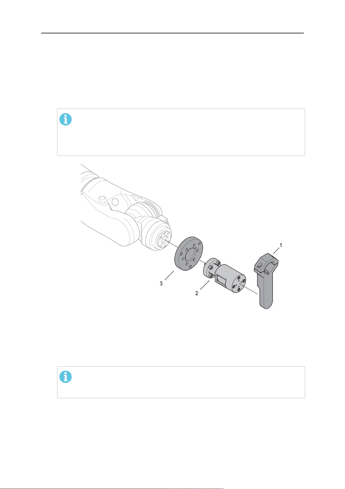
3.1 Обзор систем сварочных горелок
Стандартная система RT
Подробное описание см. в
соответствующем разделе главы
«ТЕХНИЧЕСКИЕ ХАРАКТЕРИСТИКИ»:
1. Шейка горелки
См. «Сварочная горелка».
2. Кабель в сборе
См. «Кабельные сборки для
стандартной системы RT».
3. Держатель горелки
См. «Держатели горелки для
стандартной системы RT».
4. Механизм аварийного
отключения RTKS-2
См. «Механизм аварийного
отключения RTKS-2».
5. Промежуточный фланец
RTFL-2
См. «Промежуточный фланец
RTFL-2».
6. Переходной фланец (при
необходимости)
См. «Переходные фланцы».
0463 373 101
- 12 -
© ESAB AB 2018
3 ВВЕДЕНИЕ
Система с полым запястным шарниром
Подробное описание см. в
соответствующем разделе главы
«ТЕХНИЧЕСКИЕ ХАРАКТЕРИСТИКИ»:
1. Шейка горелки
См. «Сварочная горелка».
2. Держатель горелки RTKSC-2
См. «Держатель горелки
RTKSC-2 с механизмом
аварийного отключения».
3. Держатель горелки RTFLC-2
См. «Жесткий держатель горелки
RTFLC-2».
4. Переходной фланец
См. «Переходные фланцы».
5. Кабельная сборка Helix или
Infiniturn
См. «Кабельные сборки для
систем с полым запястным
шарниром».
0463 373 101
- 13 -
© ESAB AB 2018

4 ТЕХНИЧЕСКИЕ ХАРАКТЕРИСТИКИ
4 ТЕХНИЧЕСКИЕ ХАРАКТЕРИСТИКИ
4.1 Шейка сварочной горелки
Выберите модель горелки в соответствии с видом сварочных работ. Необходимо
учитывать требуемый рабочий цикл и нагрузку, метод охлаждения и диаметр
проволоки. Обратите внимание на повышенные требования, например при работе с
предварительно нагретым свариваемым материалом или при повышенном отражении
тепла в угловых швах, и выбирайте сварочную горелку с достаточной номинальной
нагрузкой.
Сварочные горелки RT предназначены для использования с источниками сварочного
тока, соответствующими нормам ЕС при сварке металлическим электродом в среде
инертного газа (MIG), сварке металлическим электродом в среде активного газа (MAG)
и пайке в среде инертного газа с использованием сварочной проволоки круглого
сечения. Не используйте горелку для других процессов.
Для импульсно-дуговой сварки стали или алюминия необходимо использовать горелку
RT82W с водяным охлаждением.
См. доступные модели горелок ниже.
Модель горелки
Метод охлаждения Защитный газ Номинальные
RT42G Охлаждение газом CO
Охлаждение газом 300A / 100%
Охлаждение газом Смесь 350A / 60%
Охлаждение газом 250A / 100%
RT42W Охлаждение водой CO
Охлаждение водой 420A / 100%
Охлаждение водой Смесь 350A / 60%
Охлаждение водой 350A / 100%
RT52G Охлаждение газом CO
Охлаждение газом 300A / 100%
Охлаждение газом Смесь 350A / 60%
Охлаждение газом 250A / 100%
RT52W Охлаждение водой CO
Охлаждение водой 470A / 100%
Охлаждение водой Смесь 400A / 60%
значения
2
2
2
2
420A / 60%
420A / 60%
420A / 60%
470A / 60%
Охлаждение водой 400A / 100%
RT62G Охлаждение газом CO
Охлаждение газом 340A / 100%
Охлаждение газом Смесь 420A / 60%
Охлаждение газом 290A / 100%
RT62W Охлаждение водой CO
Охлаждение водой 530A / 100%
Охлаждение водой Смесь 450A / 60%
Охлаждение водой 450A / 100%
0463 373 101
- 14 -
2
2
500A / 60%
530A / 60%
© ESAB AB 2018

4 ТЕХНИЧЕСКИЕ ХАРАКТЕРИСТИКИ
Модель горелки
RT72G Охлаждение газом CO
Метод охлаждения Защитный газ Номинальные
значения
2
480А / 60%
Охлаждение газом 320A / 100%
Охлаждение газом Смесь 400A / 60%
Охлаждение газом 270A / 100%
RT72W Охлаждение водой CO
2
480A / 60%
Охлаждение водой 430A / 100%
Охлаждение водой Смесь 480A / 60%
Охлаждение водой 430A / 100%
RT82W Охлаждение водой CO
2
600A / 60%
Охлаждение водой 600A / 100%
Охлаждение водой Смесь 550A / 60%
Охлаждение водой 550A / 100%
Номинальные значения параметров горелки и рабочего цикла действительны для
10-минутного цикла.
Технические характеристики действительны для стандартного применения, при
котором используются стандартные изнашиваемые/запасные части. При
использовании режима переноса металла при импульсно-дуговой сварке номинальные
значения параметров горелки снижаются.
Диапазоны температур Хранение: -15-50°C (5-122°F)
Эксплуатация: 5–40°C (41–104°F)
Продувочный газ Макс. 10 бар, отдельный газовый шланг
Общая масса (шейка горелки, механизм
Приблизительно 5 кг
аварийного отключения, держатель
горелки и кабельная сборка 1 м)
4.2 Номинальное напряжение
Макс. допустимое напряжение / сила
тока
Система сварочной горелки в сборе 141 В (пиковое значение для сварки)
Цепь аварийного отключения RTKS-2
Кнопка RTKS-2
Цепь аварийного отключения RTKSC-2 48 V
Использование функции датчика сопла со
стандартной кабельной сборкой
24 В / 1 А
48 В / 0,1 А
50 В / 5 А
(Допустимая нагрузка макс. 1 минута при
номинальном токе)
Использование функции датчика сопла с
кабельными сборками Helix или Infiniturn
50 В / 5 А
(Допустимая нагрузка макс. 1 минута при
номинальном токе)
Указанные номинальные значения параметров применимы в случае
стандартизованного использования.
0463 373 101
- 15 -
© ESAB AB 2018
4 ТЕХНИЧЕСКИЕ ХАРАКТЕРИСТИКИ
Номинальные характеристики кабельных сборок см. в разделе «Кабельные сборки».
4.2.1 Предельные значения контура охлаждения
Только для моделей с водяным охлаждением.
Мин. скорость подачи воды: 1,0 л/мин (1,1 кварты/мин)
Мин. давление воды: 2,5бар (36,3фунта/кв.дюйм)
Макс. давление воды: 3,5бар (50,8фунта/кв.дюйм)
Температура подвода: Макс. 40°C (104°F)
Температура возврата: Макс. 60 °C (140 °F)
Охлаждающая
способность:
Мин. 1000 Вт, в зависимости от применения
ОСТОРОЖНО!
Температура возврата выше 60°C (140°F) может привести к повреждению или
выходу из строя кабельной сборки.
4.3 Держатель горелки
Тип необходимого держателя горелки зависит от конструкции сварочной горелки RT и
выбора предохранительных устройств, см. раздел «Обзор систем сварочных горелок».
Компонент Приблизительная масса
Держатель горелки (для стандартной
системы)
Механизм аварийного отключения RTKS-2
(для стандартной системы)
Промежуточный фланец RTFL-2 (для
стандартной системы)
Держатель горелки RTKSC-2 (для
системы с полым запястным шарниром)
0,43 кг
0,85 кг
0,35 кг
1,90 кг
Жесткий держатель горелки RTFLC-2 (для
1,22 кг
системы с полым запястным шарниром)
Роботизированная сварочная горелка 0,66 кг
4.3.1 Держатели горелки для стандартной системы RT
Для стандартных систем RT держатель горелки устанавливают на механизм
аварийного отключения RTKS-2 (или на промежуточный фланец RT FL-2), подключая
кабельный узел и подсоединенную шейку горелки.
Выберите держатель горелки в соответствии с типом горелки и ее геометрией. Можно
использовать разные типы держателей. См. доступные держатели горелки для
стандартной системы RT в перечне запасных частей.
0463 373 101
- 16 -
© ESAB AB 2018

4 ТЕХНИЧЕСКИЕ ХАРАКТЕРИСТИКИ
Держатель горелки для роботов со стандартными манипуляторами
4.3.1.1 Механизм аварийного отключения RTKS-2
Механизм аварийного отключения RTKS-2 представляет собой подпружиненное
устройство, которое обеспечивает защиту робота и системы горелки в случае
столкновения.
ПРИМЕЧАНИЕ!
Запрещено разбирать RTKS-2.
4.3.1.2 Промежуточный фланец RTFL-2
Жесткий промежуточный фланец RTFL-2 можно использовать вместо RTKS-2, если
робот оснащен электронной системой обнаружения столкновения.
0463 373 101
- 17 -
© ESAB AB 2018

4 ТЕХНИЧЕСКИЕ ХАРАКТЕРИСТИКИ
4.3.2 Держатели горелки для систем с полым запястным шарниром
В системах с полым запястным шарниром шейки сварочной горелки AristoRT
подсоединяются к держателю горелки KSC-2 или FLC-2.
Держатель горелки RTKSC-2 допускает упругое отклонение горелки в случае
столкновения. Одновременно с этим размыкается электрический контакт, подавая
системе управления роботом сигнал к остановке. После сброса ошибки исходная
геометрия и центральная точка инструмента (TCP) горелки будут восстановлены с
высокой точностью. Система подпружинена и работает исключительно механически.
Держатель горелки RTFLC-2 не имеет встроенной функции аварийного отключения.
Для систем с полым запястным шарниром рекомендуется использовать RTKSC-2 G/W
(или RTFLC-2 G/W). Этот держатель горелки применим как с газоохлаждаемыми, так и
с водоохлаждаемыми горелками серии AristoRT.
RTKSC-2 G/W RTFLC-2 G/W
Принцип работы механизма
аварийного отключения
Осевое усилие отпускания
(Fz)
Момент отпускания на
поперечной оси (Mx)
Механический Не применимо (жесткий
держатель)
650Н Не применимо (жесткий
держатель)
24 Нм Не применимо (жесткий
держатель)
Сброс после отпускания Автоматический Не применимо (жесткий
держатель)
Повторяемость Поперечная ± 0,1мм на
TCP стандартной горелки
Не применимо (жесткий
держатель)
AristoRT
Макс. отклонение Прибл. ± 8° Не применимо (жесткий
держатель)
Защитный выключатель Нормально замкнутый
Электрическая нагрузка
Не применимо (жесткий
держатель)
макс. 48В / 1А
0463 373 101
- 18 -
© ESAB AB 2018

4 ТЕХНИЧЕСКИЕ ХАРАКТЕРИСТИКИ
Электрическая цепь
управления для функции
датчика сопла
Номинальная
характеристика:
• Для кабельных сборок
Helix: макс. 50В пост.
тока / 5А, макс. 1
минута
После обнаружения
контакта быстро
отсоедините
напряжение
считывания.
• Для кабельных сборок
Infiniturn датчик сопла
имеет ограниченную
функциональность.
Обратитесь в
компанию ESAB для
подробного изучения
возможных решений
для ваших задач.
Номинальное напряжение Максимальное допустимое
напряжение для цепи
аварийного отключения:
48В.
Номинальная
характеристика:
• Для кабельных сборок
Helix: макс. 50В пост.
тока / 5А, макс. 1
минута
• Для кабельных сборок
Infiniturn: макс. 50В
пост. тока / 1А, макс. 1
минута
После обнаружения
контакта быстро
отсоедините напряжение
считывания.
4.3.2.1 Держатель горелки RTKSC-2 G/W с механизмом аварийного отключения
0463 373 101
- 19 -
© ESAB AB 2018

4 ТЕХНИЧЕСКИЕ ХАРАКТЕРИСТИКИ
НомерОписание Функция
1 Опора шейки горелки Сопряжение горелки AristoRT
2 Крышка RTKSC-2 Сборка с кабелем и сопряжения горелки
3 Резиновый кожух Защита механизма аварийного отключения
4 Корпус RTKSC-2 Допускает механическое отклонение в случае
столкновения
5 Переходной фланец Изолирующее сопряжение для запястного
шарнира робота (должно соответствовать
конкретному роботу)
6 Стопорный штифт Для точного совмещения с переходным фланцем
7 Разъем для кабеля
управления
Электрическое соединение для сигнала
столкновения и функции датчика сопла
8 Микропереключатель Датчик обнаружения аварийной ситуации
4.3.2.2 Жесткий держатель горелки RTFLC-2 G/W
НомерОписание Функция
1 Опора шейки горелки Сопряжение горелки AristoRT
2 Крышка RTFLC-2 Сборка с кабелем и сопряжения горелки
3 Корпус RTFLC-2 Допускает механическое отклонение в случае
столкновения
4 Стопорный штифт Для точного совмещения с переходным
фланцем
0463 373 101
- 20 -
© ESAB AB 2018

4 ТЕХНИЧЕСКИЕ ХАРАКТЕРИСТИКИ
НомерОписание Функция
5 Переходной фланец Изолирующее сопряжение для запястного
шарнира робота (должно соответствовать
конкретному роботу)
6 Разъем для кабеля
управления (3-контактный)
Электрическое соединение для функции датчика
сопла (если применимо)
4.4 Переходные фланцы
Выберите переходной фланец, необходимый для установки на манипулятор робота, в
зависимости от типа робота. Доступны переходные фланцы для всех подходящих
стандартных систем и систем с полым запястным шарниром; см. перечень запасных
частей.
4.5 Кабельные сборки
Подсоединение к устройству подачи проволоки осуществляется с помощью кабельной
сборки, доступные версии в основном зависят от конструкции системы и среды
охлаждения (газ или вода); см. перечень запасных частей.
Номинальные значения указаны для кабелей длиной от 1 до 5м.
Номинальная
характеристика
(10-минутный цикл)
Стандартная
кабельная сборка
Макс. 500A /
коэффициент
нагрузки 60 %
Infiniturn Helix
Макс. 400 A /
коэффициент
нагрузки 60 %
Макс. 400 A /
коэффициент
нагрузки 60 %
С газовым
охлаждением
(смешанный газ)
Номинальная
характеристика
(10-минутный цикл)
Макс. 350A /
коэффициент
нагрузки 100 %
Макс. 600 A /
коэффициент
нагрузки 100 %
Охлаждение водой
Диапазон вращения Ограниченное
вращение
Масса
Охлаждение газом
Масса
Охлаждение водой
Длина 1,2м:
2,35 кг
Длина 1,2м:
2,35 кг
Макс. 320 A /
коэффициент
нагрузки 100 %
Макс. 550 A /
коэффициент
нагрузки 100 %
Неограниченное
вращение
Длина 1,0 м:
2,0 кг
Длина 1,0м:
2,0 кг
Макс. 320 A /
коэффициент
нагрузки 100 %
Макс. 550 A /
коэффициент
нагрузки 100 %
± 270° от
нейтрального
положения
Длина 1,0 м:
2,0 кг
Длина 1,0м:
2,0 кг
0463 373 101
- 21 -
© ESAB AB 2018

4 ТЕХНИЧЕСКИЕ ХАРАКТЕРИСТИКИ
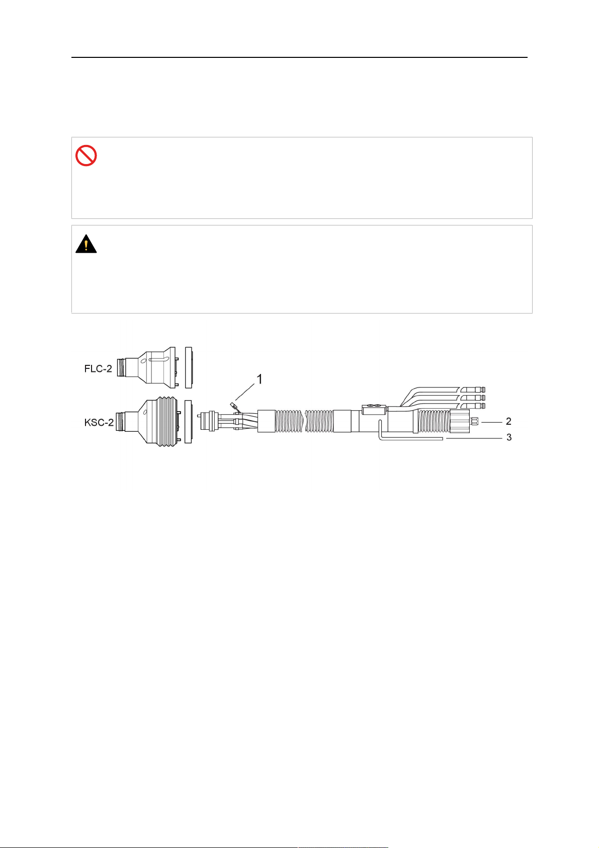
4.5.1 Кабельные сборки для стандартной системы RT
Контакты разъема Burndy
A. Обнаружение касания,
газовое сопло
C. Датчик столкновения
Е. 0В
G. + напряжение двигателя
H. - напряжение двигателя
D. Датчик столкновения
E. Медленное перемещение
НомерОписание Функция
1 Опорный фланец шейки Сопряжение с горелкой
2 Защитная крышка Защищает кабельный узел от повреждений
3 Разъем Burndy, 12-контактный Электрическое соединение между механизмом
аварийного отключения и устройством подачи
проволоки
4 Управляющий кабель Для KS-2 (механизм аварийного выключения и
кнопка)
5 Разъем EURO Подключение устройства подачи проволоки
6 Продувочный шланг (черная
крышка)
7 Подвод воды (синий колпачок)
8 Слив воды (красный колпачок)
9 Штекер кабеля управления
для механизма аварийного
Для прочистки горелки сжатым воздухом после
цикла очистки
Впуск воды для охлаждения горелки
Слив нагретой воды из горелки
1)
1)
Электрическое соединение с RTKS-2 для
сигнала аварийного отключения и датчика сопла
отключения
1)
Только для систем горелок с водяным охлаждением
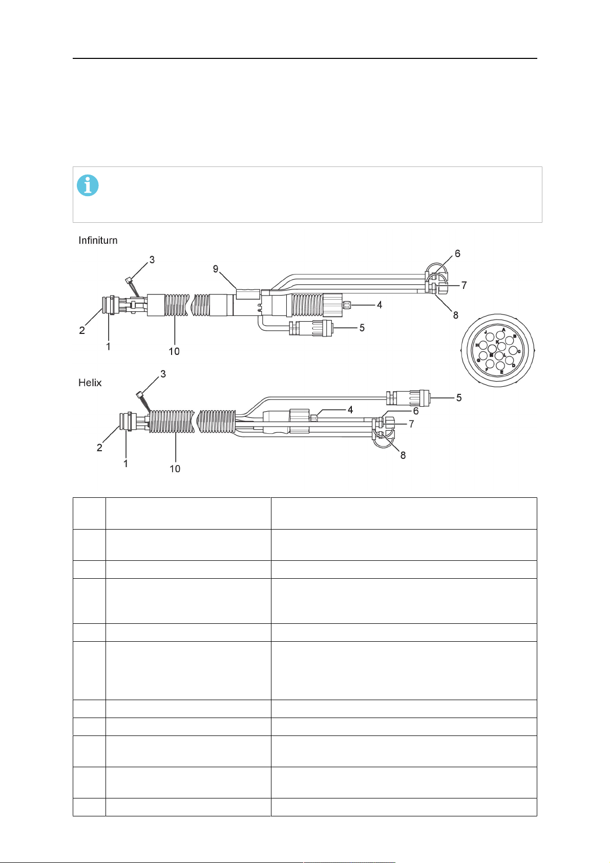
4.5.2 Кабельные сборки для систем с полым запястным шарниром
Кабельная сборка Infiniturn обеспечивает неограниченное вращение горелки в обоих
направлениях. Одновременно осуществляется передача охлаждающей жидкости,
защитного газа, продувочного воздуха, сварочной мощности и сигнала механизма
аварийного отключения.
0463 373 101
- 22 -
© ESAB AB 2018
4 ТЕХНИЧЕСКИЕ ХАРАКТЕРИСТИКИ
Кабельная сборка Helix рассчитана на вращение в диапазоне ±270° от нейтрального
положения. Ее можно использовать для сварки, не требующей неограниченного
вращения.
Кабельные сборки Infiniturn доступны в версиях с водяным и газовым охлаждением.
Кабельные сборки Helix можно использовать для систем с газовым или водяным
охлаждением.
ПРИМЕЧАНИЕ!
Запрещено подключать к системе водяного охлаждения кабельную сборку
Helix, работающую с горелкой с газовым охлаждением шейки.
НомерОписание Функция
1 Фланец Сопряжение с держателем горелки RTKSC-2 /
RTFLC-2
2 Стопорный штифт Обеспечивает правильную ориентацию муфты
3 Штепсель кабеля управления Электрическое соединение с RTKSC-2 для
сигнала аварийного отключения и датчика сопла
(если применимо)
4 Разъем EURO Подключение устройства подачи проволоки
5 Управляющий кабель Электрическое соединение для сигнала
аварийного отключения (от RTKSC-2) и датчика
сопла (функция датчика сопла является
стандартной для Helix, но не для Infiniturn)
6 Слив воды (красный колпачок) Слив нагретой воды из горелки
7 Подвод воды (синий колпачок) Впуск воды для охлаждения горелки
8 Продувочный шланг (черная
крышка)
Для прочистки горелки сжатым воздухом после
сварки
9 Муфта среды Муфта неограниченного вращения с передачей
среды
10 Защитная крышка Защищает кабельный узел от повреждений
0463 373 101
- 23 -
© ESAB AB 2018

5 INSTALLATION
5 INSTALLATION
ВНИМАНИЕ!
For your own safety, make sure that the robot is either in standby or power-less
state before doing maintenance work in the moving radius of the robot.
Follow the assembly instructions exactly. Pay attention during assembly that the cables are
not damaged. Damaged cables can lead to a short circuit, which may damage the electronics
of the robot or the welding torch.
Use only original ESAB components that have been specially developed for this purpose.
Only then the correct functioning of the whole welding torch system can be guaranteed.
5.1 RTKS-2 standard arm installation
5.1.1 RTKS-2 safety-off mechanism
1. Dismount the insulation flange (10) from the RTKS-2 (11) by removing the screws
(12).
2. Position the insulation flange (10) with the index pin on the robot arm and fix it with the
screws (20) included.
The insulation flange (10) is directly compatible with robots with tool flange according
to DIN ISO 9409-1-A40 (diameter 40mm, 4×M6). If the insulation flange (10) does
not fit, use an adapter flange (21).
ПРИМЕЧАНИЕ!
Ensure that the index pin is located correctly. The maximum torque of 1.2Nm
(10.5in.lb) must be observed for the fastening of the adapter flange screws.
Prevent self-loosening of the screws by using suitable thread locking
measures.
3. Mount the RTKS-2 the back on the insulation flange (10).
0463 373 101
- 24 -
© ESAB AB 2018

5 INSTALLATION
4. Position the mount on the RTKS-2 and carefully insert the cylindrical pins (14) into the
holes provided. Take the position of the torch into account. Two mounting positions
may be potentially possible.
5. Screw the mount evenly using the enclosed cylinder screws with hexagon socket (12).
ПРИМЕЧАНИЕ!
The maximum tightening torque for the cylinder screw (5) is 6Nm (53in.lb)
and the property class category is 8.8.
12 - Cylinder screw with hexagon socket
M6DIN912 (length of the screw depending
on the torch mount)
14 - Cylindrical pins Ø4×20
5.1.1.1 Torch installation with adjustable mount
Torch mounts with a central clamping assembly can only be fastened on the journal of the
mounting flange. For this, the mounting flange must be fastened first.
1. If applicable, carefully press the cylindrical pins (1) into the corresponding holes in the
mounting flange. The pins should protrude by approximately 5 mm (0.2 in.).
2. Position the mount on the safety-off mechanism RTKS-2 and carefully insert the
cylindrical pins (1) into the holes provided. In doing so, take the later position of the
torch into account. Two mounting positions may be potentially possible.
3. Then screw down the mounting flange evenly using the enclosed cylinder screws with
hexagon socket (2).
ПРИМЕЧАНИЕ!
The maximum tightening torque for the cylinder screw (2) is 7.1 Nm (62.8
in.lb) and the property class category is 8.8.
0463 373 101
- 25 -
© ESAB AB 2018
5 INSTALLATION
4. Unscrew the axial cylinder screw with hexagon socket (4) out of the mounting flange
together with the washer (3).
1 - Cylindrical pins Ø4×14 3 - Washer Ø9 mm
2 - Cylinder screw with hexagon socket
M6×16
4 - Axial cylinder screw with hexagon
socket M8×16
5. Place the torch mount (5) onto the journal (6) of the mounting flange, paying attention
while doing so to the exact alignment of the feather key (7) and the corresponding
groove (7a).
6. Insert the clamping mandrel (8) into the lateral hole (see illustration) and position it so
that the mating surfaces (9a) of the clamping mandrel rest on the mating surface (9) of
the journal.
0463 373 101
- 26 -
© ESAB AB 2018

5 INSTALLATION
7. Fix the clamping mandrel from the opposite side using the M6 cylinder screw with
hexagon socket (10) and the Ø22 mm washer (11).
8. Screw the axial cylinder screw (4) with the Ø9 mm washer (3) into the mounting flange
and tighten firmly.
3 - Washer Ø9 mm 8 - Clamping mandrel
4 - Axial cylinder screw with hexagon
9 - Mating surface of mounting flange
socket M8×16
5 - Torch mount 9a - Mating surfaces of clamping mandrel
6 - Mounting flange journal 10 - Cylinder screw with hexagon socket
M6×30
7 Feather key 11 - Washer Ø22×6.4 mm
7a - Groove for feather key
5.1.2 Standard arm cable assembly for KS-2 and FL-2
The cable assembly must be aligned to the intended use in length and design. The type of
cooling for the torch and the cable assembly must be the same (either gas or water cooled
respectively). In order to prevent damage to the torch system and other components, it is
imperative to observe the following instructions.
0463 373 101
- 27 -
© ESAB AB 2018

5 INSTALLATION
ОСТОРОЖНО!
• Coordinate the length and design of the cable assembly to suit the range of
action of the robot.
• Do not bend, compress or overstretch the cable assembly.
• Fix the cable assembly such that is can be moved freely and cannot become
entangled.
• Any additional holding devices possibly installed, for example a balancer,
must not crush or bend the cable assembly.
• Extreme turning movements must be avoided in which the cable assembly
may become twisted.
• Chafing on the robot or other objects must be excluded.
1. Unscrew the cylinder screws (1) and lift off the top section (2) of the torch mount.
2. Insert the feather key (4) into the recess of the neck support flange (3) from below.
3. Align the neck support flange (3) including the feather key (4) to the groove (5) of the
torch mount and push into the groove right up to the stop of the flange.
4. Hold the cable assembly in this position and simultaneously place the top section (2)
back onto the torch mount. First screw both cylinder screws (1) loosely in to about the
same length, then tighten alternately. The top section (2) of the mount should have an
even gap to the bottom section.
The front part of the cable assembly is directly clamped into the torch mount (see
illustration below).
1 - Cylinder screws 4 - Feather key
2 - Torch mount top section 5 - Groove for feather key
3 - Neck support flange
5.1.3 RTKS-2 wire feeder connection
In order to be able to create the connection, the cable assembly must be mounted as
described in the "Installing the cable assembly" section and equipped following "Installing the
wire guide" section. Only then can the central and media connection take place. Proceed as
described below:
0463 373 101
- 28 -
© ESAB AB 2018
5 INSTALLATION
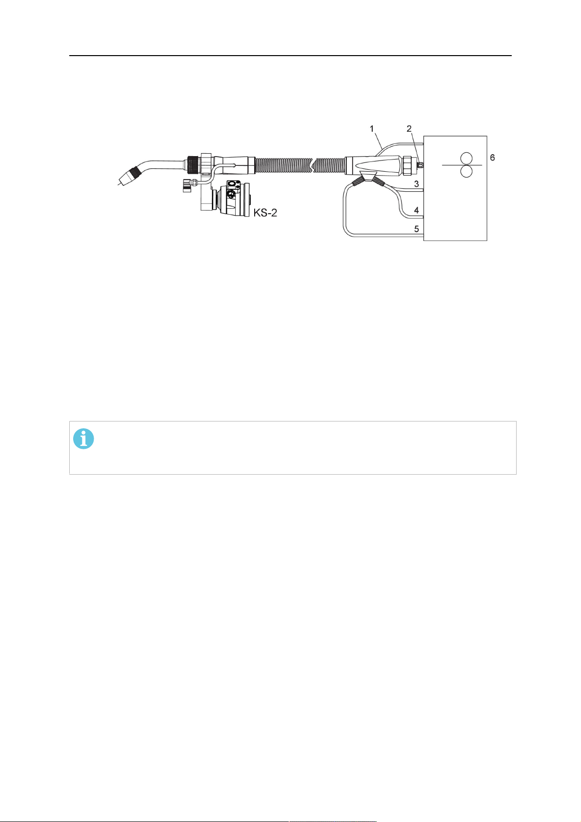
1. Connect the central connector of the cable assembly (2) to the wire feeder cabinet
socket. Tighten the central connector sleeve nut fingertight. Do not use tools.
1 - Burndy Connector 4 - Return of heated water (red cap)
2 - EURO central connector 5 - Return of heated water (red cap)
3 - Air blow-out 6 - Main Wire feeder
2. For water cooled systems. Connect the water hoses to the cooling circuit. The end of
the hose marked blue (4) is connected to the water outlet, and the end marked red (5)
is connected to the water return.
3. Connect the blow-out line (3) to the corresponding connection of the feeder.
4. Connect the Burndy Connector to the wire feeder. (1) to the feeder. See section
"Electrical connections".
ПРИМЕЧАНИЕ!
All hoses and the control line must be installed so they can not bend or get
damaged!
5.1.4 RTKS-2 electrical connections
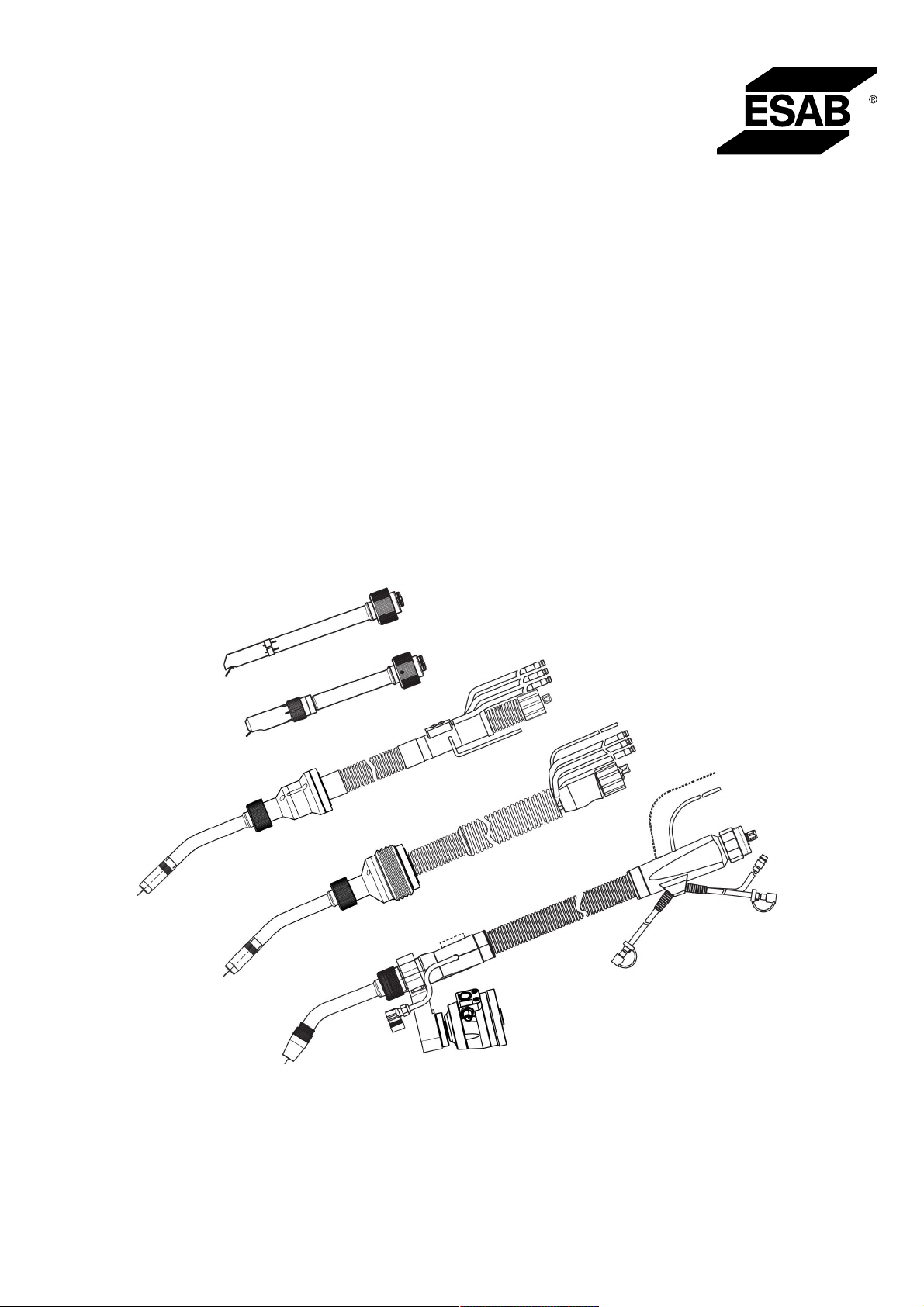
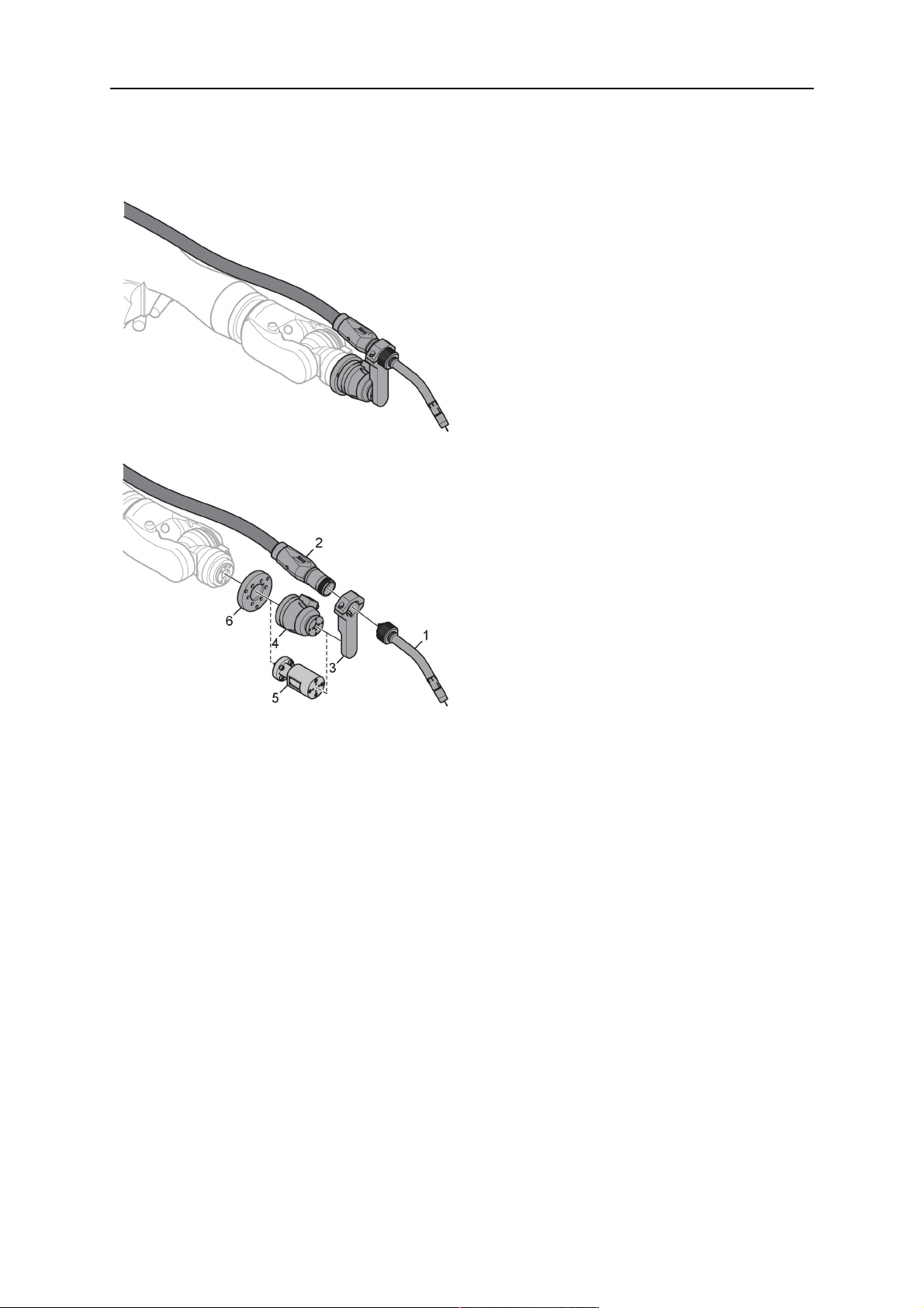
5.1.4.1 RTKS-2 safety-off mechanism connection
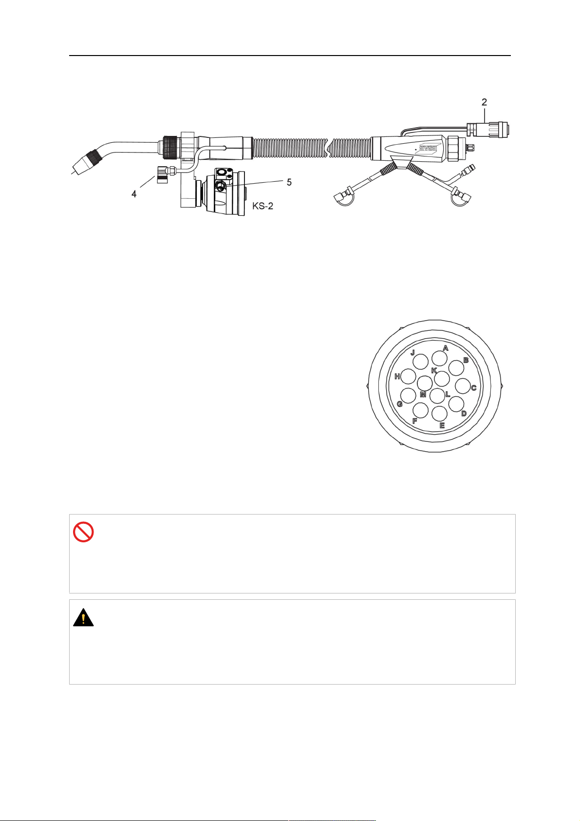
The switch for the safety-off functionality RTKS-2 is connected through the control cable,
see (3) in the illustration below. This connects to the RTKS-2 unit via the 4-pole plug (4) that
contains circuits for the push-button (6) and the safety-off signal (7).
If a collision is detected, the control circuit for the safety-off signal (7), which is normally
closed, will be interrupted.
Rating of the control circuit: max. 48 V / 1 A
0463 373 101
- 29 -
© ESAB AB 2018
5 INSTALLATION
2 - Burndy connector 5 - RTKS-2 connector for control cable plug
4 - Control cable plug
Контакты разъема Burndy
A. Обнаружение касания,
газовое сопло
C. Датчик столкновения
Е. 0В
G. + напряжение двигателя
H. - напряжение двигателя
D. Датчик столкновения
E. Медленное перемещение
If the robot control provides a control circuit for nozzle sense functionality, the connection is
accomplished with a 1-wire connection.
Rating of the control circuit: max 50 V / 5 A.
ОПАСНО!
If the nozzle sense function is not being used, the open end of the control cable on
the power source connection side must be properly isolated in order to avoid short
circuits. During certain problems on the torch head, the full welding potential may be
present on this cable.
ОСТОРОЖНО!
After detection of contact (gas nozzle on work piece), quickly reduce or cut off the
maximum current in the nozzle sense circuit in order to avoid overloading of the
system.
Allowed load max. 1 minute at the rated nominal current.
5.1.5 RTKS-2 Torch installation
Continue according to section "Torch installation".
0463 373 101
- 30 -
© ESAB AB 2018
5 INSTALLATION
5.2 RTFL-2 standard arm installation
5.2.1 RTFL-2 rigid mount
1. Position the RT FL-2 (2) with the index pin on the robot arm and fix it with the hexagon
socket screw included.
The FL-2 is directly compatible with robots with tool flange according to DIN ISO
9409-1-A40 (diameter 40mm, 4×M6). If the rigid mount does not fit, use an adapter
flange (3).
ПРИМЕЧАНИЕ!
Ensure that the index pin is located correctly. The maximum torque of 1.2Nm
(10.5in.lb) must be observed for the fastening of the adapter flange screws.
Prevent self-loosening of the screws by using suitable thread locking
measures.
2. Install torch mount (1). Only torch mounts having a hole pattern equivalent with the
mounting surface may be attached. If necessary, carefully press the cylindrical pins (4)
into the corresponding holes in the bracket. The pins should protrude by
approximately 5mm (0.2in.). Position the torch mount on the RTFL-2 (2) and
carefully insert the cylindrical pins (4) into the holes provided. Take the position of the
torch into account. Two mounting positions may be potentially possible.
3. Screw the mount evenly using the enclosed cylinder screws with hexagon socket (5).
ПРИМЕЧАНИЕ!
The maximum tightening torque for the cylinder screw (5) is 6Nm (53in.lb)
and the property class category is 8.8.
0463 373 101
- 31 -
© ESAB AB 2018

5 INSTALLATION
4 - Cylindrical pins Ø4×20
5 - Cylinder screw with hexagon socket M6
DIN 912 (length of the screw depending on
the torch mount)
Side view
Torch installation with adjustable mount
Torch mounts with a central clamping assembly can only be fastened on the journal of the
mounting flange. For this, the mounting flange must be fastened first.
1. If applicable, carefully press the cylindrical pins (1) into the corresponding holes in the
mounting flange. Avoid the formation of burrs. The pins should protrude by
approximately 5 mm (0.2 in.).
2. Position the mount on the RTFL-2 and carefully insert the cylindrical pins (1) into the
holes provided. In doing so, take the later position of the torch into account. Two
mounting positions may be potentially possible.
3. Then screw down the mounting flange evenly using the enclosed cylinder screws with
hexagon socket (2).
ПРИМЕЧАНИЕ!
The maximum tightening torque for the cylinder screw (2) is 7.1 Nm (62.8
in.lb) and the property class category is 8.8.
4. Unscrew the axial cylinder screw with hexagon socket (4) out of the mounting flange
together with the washer (3).
1 - Cylindrical pins Ø4×14 3 - Washer Ø9 mm
2 - Cylinder screw with hexagon socket
M6×16
4 - Axial cylinder screw with hexagon
socket M8×16
5. Place the torch mount (5) onto the journal (6) of the mounting flange, paying attention
while doing so to the exact alignment of the feather key (7) and the corresponding
groove (7a).
0463 373 101
- 32 -
© ESAB AB 2018

5 INSTALLATION
6. Insert the clamping mandrel (8) into the lateral hole (see illustration) and position it so
that the mating surfaces (9a) of the clamping mandrel rest on the mating surface (9) of
the journal.
7. Fix the clamping mandrel from the opposite side using the M6 cylinder screw with
hexagon socket (10) and the Ø22 mm washer (11).
8. Screw the axial cylinder screw (4) with the Ø9 mm washer (3) into the mounting flange
and tighten firmly.
3 - Washer Ø9 mm 8 - Clamping mandrel
4 - Axial cylinder screw with hexagon
9 - Mating surface of mounting flange
socket M8×16
5 - Torch mount 9a - Mating surfaces of clamping mandrel
6 - Mounting flange journal 10 - Cylinder screw with hexagon socket
M6×30
7 - Feather key 11 - Washer Ø22×6.4 mm
7a - Groove for feather key
5.2.2 RTFL-2 torch installation
Continue according to section "Torch installation".
5.3 RTKSC-2 hollow wrist system installation
5.3.1 RTKSC-2 mount with safety off mechanism
ОСТОРОЖНО!
For hollow wrist systems make sure that the clear space around the robot is at least
Ø45 mm (1.8 in.) around the wrist and 50 mm (2.0 in.) near the wire feeder.
0463 373 101
- 33 -
© ESAB AB 2018

5 INSTALLATION
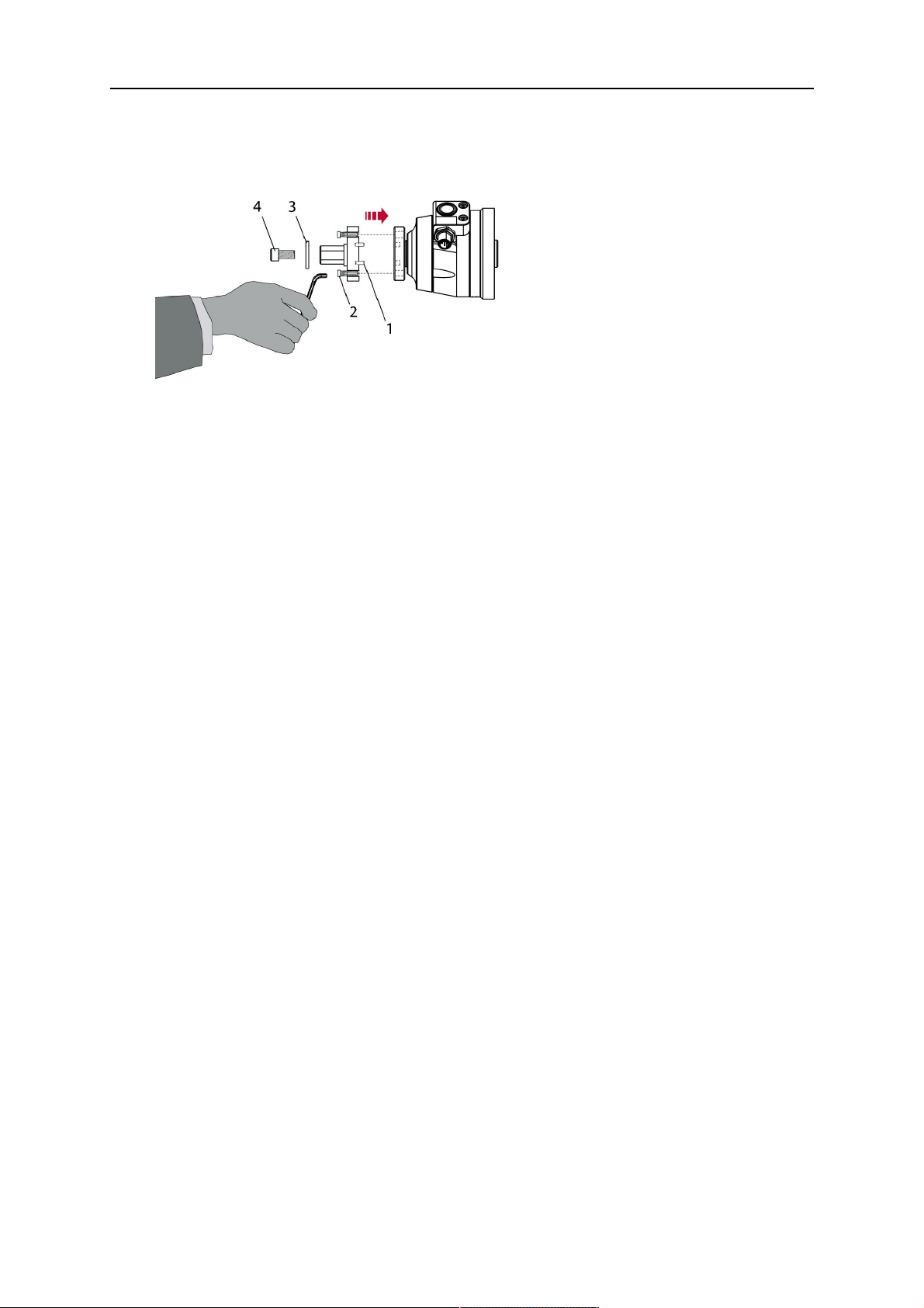
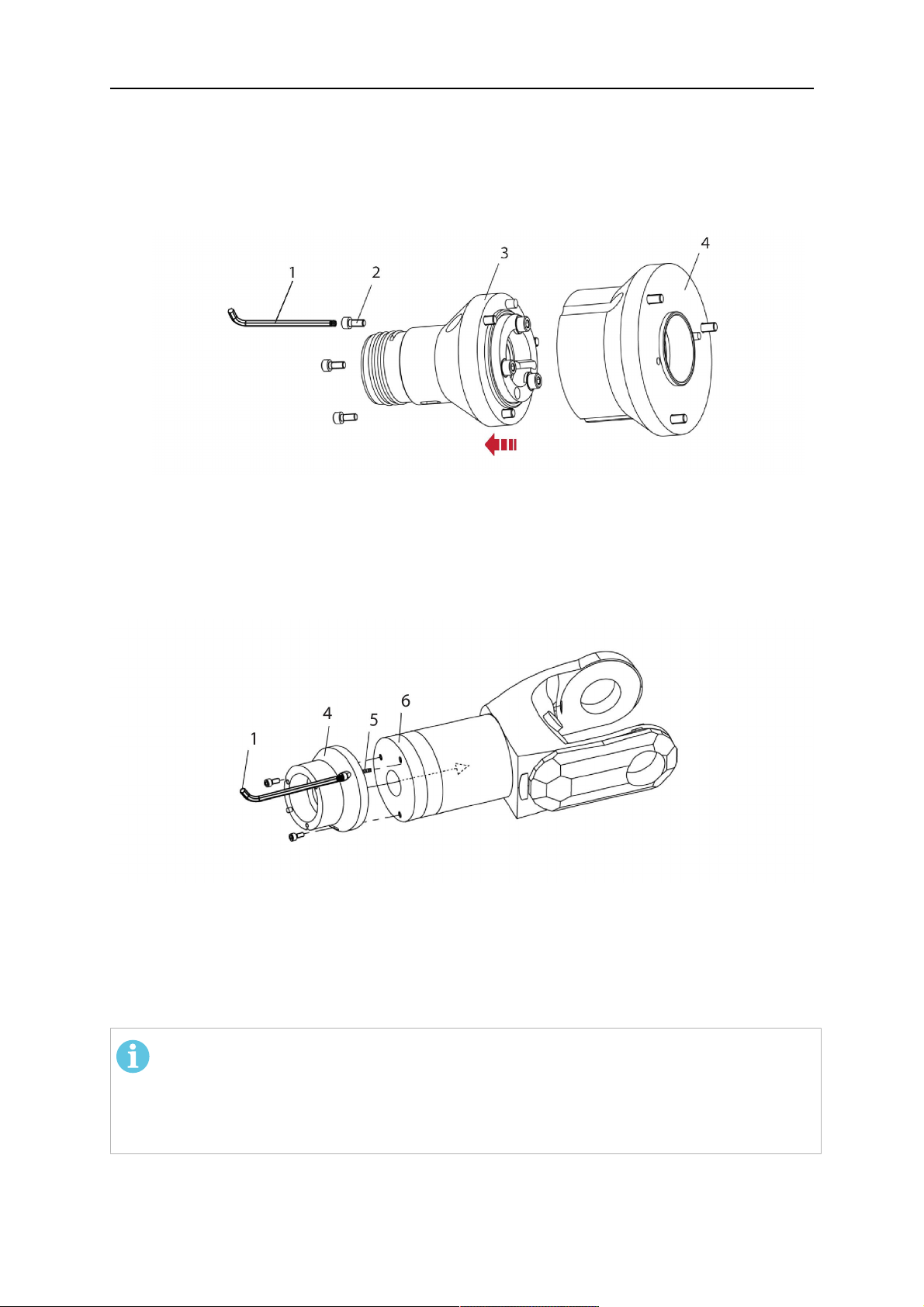
1. Remove the three screws (2) from the front cover (3) of the torch mount and carefully
pull the cover off the RTKSC-2 main body (5). Take care not to damage the micro
switches installed inside the assembly.
1 - Hexagon wrench 4 mm 4 - Rubber boot
2 - 3× M5×12 screws 5 - RT KSC-2 main body
3 - RT KSC-2 front cover
1. Pull off the rubber boot (4) from the RTKSC-2 main body (5) to the front.
2. Now position the RTKSC-2 main body (5) on the adapter flange (7) so that the index
pin is correctly seated. Attach with the screws (6) enclosed.
3. Reinstall the rubber boot (4) on the RTKSC-2 main body (5) and make sure it is
correctly located in the grooves on the front and back flange.
4. Istall the adapter flange (7) on the robot.
Fastening torque max. 2.2 Nm (19.5 in.lb).
1 - Hexagon wrench 4 mm 3 - 3× M5×12 hexagon socket screws
2 - Rubber boot 4 - Adapter flange
5.3.2 Mounting the cable assembly
ПРИМЕЧАНИЕ!
In order to adjust the wire feeder position to the cable assembly length, it must be
mounted on an adjustable support with a possible movement of ±2-3cm (±1in.) to
the back and to the front. The length of the cable assembly must be determined
from the centred mounting position of the wire feeder.
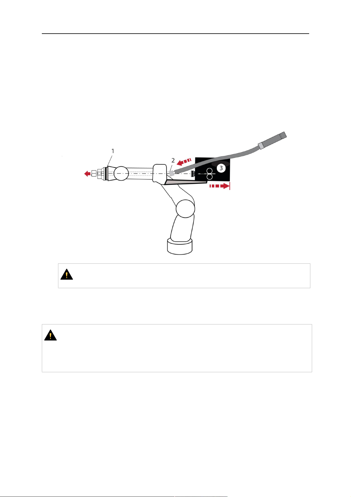
1. Move the robot arm into a completely straight position, see illustration below. Make
sure that (1) axis 6 (rotation around the torch axis) is in 0° position.
2. Move the feeder (3) completely to the back in order to create space for inserting the
cable assembly. If it is not possible to move the feeder sufficiently, it should be
removed from the robot.
0463 373 101
- 34 -
© ESAB AB 2018

5 INSTALLATION
3. Insert the cable assembly with the coupling (2) first into the robot arm and feed it
through the robot wrist.
4. The feeder should only be installed again after the correct mounting position with
respect to the cable length has been determined. (See section "Installing the cable
assembly").
ОСТОРОЖНО!
Axis 6 must be in 0° position.
5.3.2.1 RTKSC-2 feeder cabinet connections
When installed for the first time, the position of the wire feeder cabinet must be adjusted to
the length of the cable assembly. First, the robot arm must be fully extended (straight).
ОСТОРОЖНО!
As long as the correct position of the feeder corresponding to the length of the cable
assembly has not been determined, be careful when moving the robot arm and
avoid overstretching the cable. It is helpful to loosen the positioning screws of the
feeder before moving the robot arm to allow the feeder to follow the cable assembly.
0463 373 101
- 35 -
© ESAB AB 2018

5 INSTALLATION
1. Loosen the sliding mechanism of the wire feeder and connect the cable assembly.
2. Now adjust the position of the wire feeder to suit the length of the Infiniturn or Helix
cable, as indicated with "A" in the illustration below.
ОСТОРОЖНО!
When adjusting the position of the feeder cabinet, make sure that the cable
assembly is not under stress when the robot arm is in stretched-out position.
It is normal for the cable assembly to sag slightly, it should never be taut.
3. Before securing the wire feeder in its permanent position, ensure that the Euro
connectors are tightly connected. Then turn the torch mount down and up again
(rotating on the axis 5), in order not to tighten the cable assembly too much against
the feeder (see illustration above). Once this is done, tighten the feeder in that
position.
4. For water cooled systems, connect the water lines to the cooling circuit. See section
"Cable assemblies for hollow wrist systems" in the TECHNICAL DATA chapter for
indications.
The hose with the blue rubber cap is for cooling water to the torch, the hose with the
red rubber cap returns the heated water. Make sure the hoses will not kink or get
otherwise blocked.
ПРИМЕЧАНИЕ!
A Helix cable assembly used for a gas cooled system must not be connected
to a cooling circuit. As the water connections are not needed, they may be cut
off.
5. Connect the blow-out hose (black rubber cap) to the corresponding outlet of the wire
feeder.
ПРИМЕЧАНИЕ!
If the blow-out function is not used, the blow-out hose must be sealed with the
rubber cap enclosed. With Infiniturn systems, the blow-out air must be
supplied to the corresponding connection hose, if it is not permitted to connect
blow-out air to the shield gas connection!
6. Install the necessary plug on the control cable and connect it to the safety off circuit
interface of the wire feeder (see section "Electrical connections").
0463 373 101
- 36 -
© ESAB AB 2018

5 INSTALLATION
5.3.3 RTKSC-2 cable assembly
The cable assembly must be aligned to the intended use in length and design. The type of
cooling for the torch and the cable assembly must be the same (either gas or water cooled
respectively). In order to prevent damage to the torch system and other components, it is
imperative to observe the following instructions.
ОСТОРОЖНО!
• Coordinate the length and design of the cable assembly to suit the range of
action of the robot.
• Do not bend, compress or overstretch the cable assembly.
• Fix the cable assembly such that is can be moved freely and cannot become
entangled.
• Any additional holding devices possibly installed, for example a balancer,
must not crush or bend the cable assembly.
• Extreme turning movements must be avoided in which the cable assembly
may become twisted.
• Chafing on the robot or other objects must be excluded.
5.3.3.1 RTKSC-2 cable assembly installation
ПРИМЕЧАНИЕ!
For some robots, it may be possible to deviate from this order, and first connect the
cable assembly to the RTKSC-2, then thread the cable from the front through the
robot arm. If in doubt, follow the suggested order.
1. Loosen the three screws (7) with the associated washers and remove them from the
RTKSC-2 cover (1). See illustration below.
2. Install the supplied O-rings (4) into the grooves in the cover (1).
3. Pull the cable assembly approximately 15 cm (6 in.) from the main body (3).
0463 373 101
- 37 -
© ESAB AB 2018

5 INSTALLATION
4. Insert the coupling (2) into the socket of the cover (1) as shown. Align the index pin (6)
with the index hole (5) in the main body and insert completely.
ПРИМЕЧАНИЕ!
Make sure that the position of the O-rings are not shifted by the index pin
during the assembly.
1 - RTKSC-2 cover 5 - Index hole
2 - Coupling 6 - Index pin
3 - RTKSC-2 main body 7 - 3× M5×35 screws
4 - 3× O-ring for water cooled systems 11 - Control cable connector
5. Insert the three screws (7) with the associated washers (8) and tighten gently with the
enclosed hexagonal wrench, see below illustration.
Fastening torque approximately 2 Nm (18 in.lb).
0463 373 101
- 38 -
© ESAB AB 2018

5 INSTALLATION
6. If present, insert the control cable plug (10) into the connector (11) and make sure it is
firmly seated.
7 - 3× M5×35 screw 11 - Control cable connector
8 - Washer 12 - 2× Micro switch
10 - Control cable plug 13 - Index pin
7. Gently push back the cable assembly into the robot arm and carefully seat the
RTKSC-2 cover (1) in place. Observe the index pin (13) to be in the correct position.
Make sure the two micro switches (12) are not damaged if present.
8. Insert the three M5 screws (14) and tighten without excessive force.
13. Index pin
14. 3× M5×12 screws
0463 373 101
- 39 -
© ESAB AB 2018

5 INSTALLATION
5.3.3.2 RTKSC-2 electrical connections
ПРИМЕЧАНИЕ!
After connecting the control cable, secure the cable in order to protect it from getting
caught while the robot is moving.
Usually, the control cable will be directly connected to the wire feeder. See the
manufacturer's documentation for details. The link to the robot control is then
implemented via the power source controller.
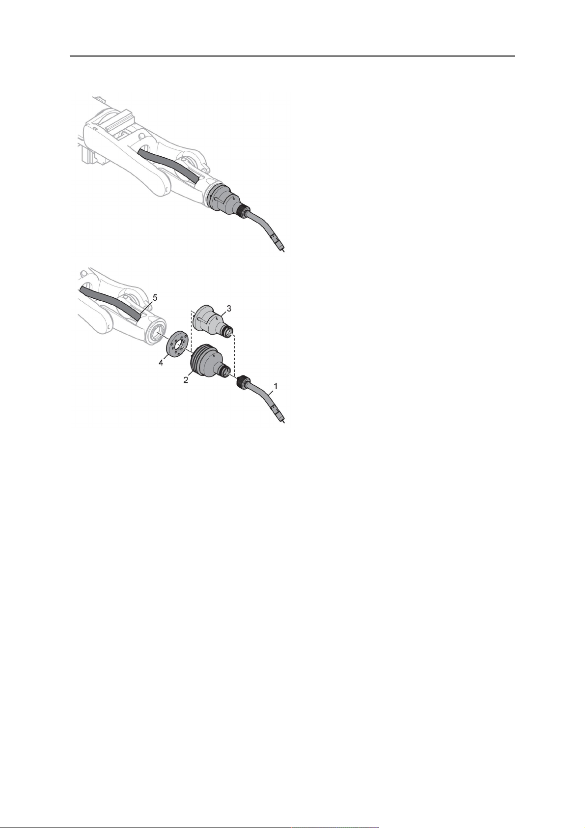
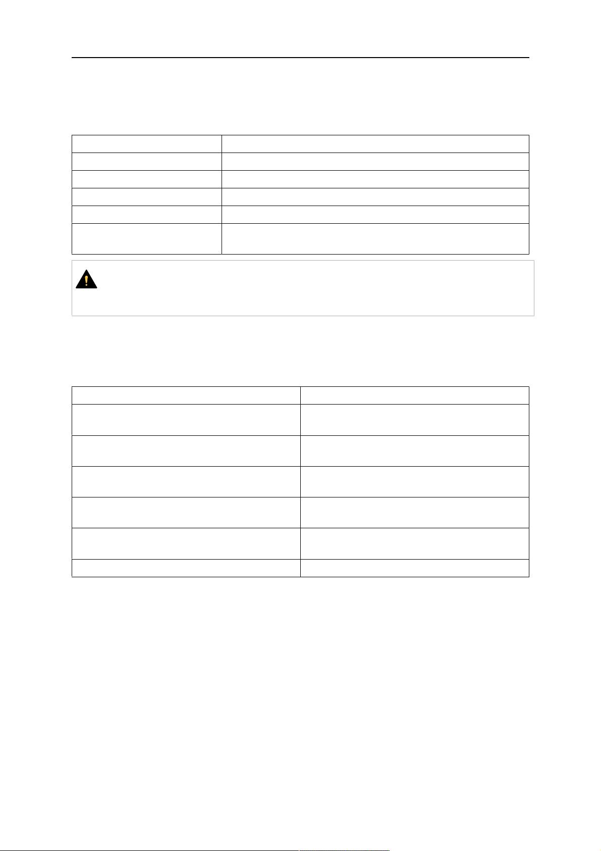
RTKSC-2 safety-off mechanism connection
The switch for the safety-off functionality RTKSC-2 is connected through the control cable,
see (3) in the illustration below. This connects to the RTKSC-2 unit via the control cable plug
(1).
The safety-off signal requires a 2-wire connection (black/black) to the safety-off circuit in the
robot control (5).
If a collision is detected, the control circuit (normally closed) will be interrupted (4).
Rating of the control circuit: max. 48 V / 1 A.
1 - Control cable plug 3 - Burndy connector VVV
2 - EURO central connector
Контакты разъема Burndy
A. Обнаружение касания,
газовое сопло
C. Датчик столкновения
Е. 0В
G. + напряжение двигателя
H. - напряжение двигателя
D. Датчик столкновения
E. Медленное перемещение
RTKSC-2 nozzle sense function connection
If the robot control provides a control circuit for nozzle sense functionality.
The connection is accomplished with a 2-wire connection (black/black) to the nozzle sense
circuit in the robot control (5), see illustration below.
0463 373 101
- 40 -
© ESAB AB 2018
5 INSTALLATION
Usually, the control cable will be directly connected to the wire feeder. See the
manufacturer's documentation for details. The link to the robot control is then implemented
via the power source robot interface.
Rating of the control circuit: max. 50 V / 5 A.
ОПАСНО!
If the nozzle sense function is not being used, the open end of the control cable on
the power source connection side must be properly isolated in order to avoid short
circuits. During certain problems on the torch head, the full welding potential may be
present on this cable.
ОСТОРОЖНО!
After detection of contact (gas nozzle on work piece), quickly reduce or cut off the
maximum current in the nozzle sense circuit in order to avoid overloading of the
system.
Allowed load max. 1 minute at the rated nominal current.
1 - Control cable plug 3 - Control cable
2 - EURO central connector
5.3.4 RTKSC-2 torch installation
Continue according to section "Torch installation".
0463 373 101
- 41 -
© ESAB AB 2018
5 INSTALLATION
5.4 RTFLC-2 installation
5.4.1 RTFLC-2 mount
1. Remove the three M5 screws (2) from the front cover (3) of the RT FLC-2 torch mount
and carefully pull the cover off the main body (4).
1 - Hexagon wrench 4 mm 3 - RT FLC-2 front cover
2 - 3× M5×12 screws 4 - RT FLC-2 main body
2. Now position the RT FLC-2 main body (4) on the adapter flange (6) so that the index
pin is correctly seated. Attach with the screws (5) enclosed
Fastening torque max. 2.2 Nm (19.5 in.lb).
1 - Hexagon wrench 4 mm 5 - 3× M5×12 hexagon socket screws
4 - RT FLC-2 main body 6 - Adapter flange
5.4.2 RTFLC-2 wire feeder connection
5.4.2.1 Feeding through the robot arm
ПРИМЕЧАНИЕ!
In order to adjust the wire feeder position to the cable assembly length, it must be
mounted on an adjustable support with a possible movement of ± 2-3 cm (± 1 in.) to
the back and to the front. The length of the cable assembly must be determined
from the centred mounting position of the wire feeder.
0463 373 101
- 42 -
© ESAB AB 2018
5 INSTALLATION
1. Move the robot arm into a completely straight position, see illustration below. Make
sure that (1) axis 6 (rotation around the torch axis) is in 0° position.
2. Move the feeder (3) completely to the back in order to create space for inserting the
cable assembly. If it is not possible to move the feeder sufficiently, it should be
removed from the robot.
3. Insert the cable assembly with the coupling (2) first into the robot arm and feed it
through the robot wrist.
4. The feeder should only be installed again after the correct mounting position with
respect to the cable length has been determined. (See section "Installing the cable
assembly").
ОСТОРОЖНО!
Important! Axis 6 must be in 0° position.
5.4.2.2 RTFLC-2 feeder cabinet connections
When installed for the first time, the position of the wire feeder cabinet must be adjusted to
the length of the cable assembly. First, the robot arm must be fully extended (straight).
ОСТОРОЖНО!
As long as the correct position of the feeder corresponding to the length of the cable
assembly has not been determined, be careful when moving the robot arm and
avoid overstretching the cable. It is helpful to loosen the positioning screws of the
feeder before moving the robot arm to allow the feeder to follow the cable assembly.
0463 373 101
- 43 -
© ESAB AB 2018

5 INSTALLATION
1. Loosen the sliding mechanism of the wire feeder and connect the cable assembly.
Refer to the instruction of the feeder manufacturer.
2. Now adjust the position of the wire feeder to suit the length of the Infiniturn or Helix
cable, as indicated with "A" in the illustration below.
ОСТОРОЖНО!
When adjusting the position of the feeder cabinet, make sure that the cable
assembly is not under stress when the robot arm is in stretched-out position.
It is normal for the cable assembly to sag slightly, it should never be taut.
3. Before securing the wire feeder in its permanent position, ensure that the Euro
connections are tightly connected. Then turn the torch mount down and up again
(rotating on the axis 5), in order not to tighten the cable assembly too much against
the feeder (see illustration above). Once this is done, tighten the feeder in that
position.
4. For water cooled systems, connect the water lines to the cooling circuit. See section
"Cable assemblies for hollow wrist systems" in the TECHNICAL DATA chapter for
indications.
The hose with the blue rubber cap is for cooling water to the torch, the hose with the
red rubber cap returns the heated water. Make sure the hoses will not kink or get
otherwise blocked.
ПРИМЕЧАНИЕ!
A Helix cable assembly used for a gas cooled system must not be connected
to a cooling circuit. As the water connections are not needed, they may be cut
off.
5. Connect the blow-out hose (black rubber cap) to the corresponding outlet of the wire
feeder.
ПРИМЕЧАНИЕ!
If the blow-out function is not used, the blow-out hose must be sealed with the
rubber cap enclosed. With Infiniturn systems, the blow-out air must be
supplied to the corresponding connection hose, if it is not permitted to connect
blow-out air to the shield gas connection!
0463 373 101
- 44 -
© ESAB AB 2018

5 INSTALLATION
6. Install the necessary plug on the control cable and connect it to the safety off circuit
interface of the wire feeder (see section "Electrical connections").
5.4.3 RTFLC-2 cable assembly
The cable assembly must be aligned to the intended use in length and design. The type of
cooling for the torch and the cable assembly must be the same (either gas or water cooled
respectively). In order to prevent damage to the torch system and other components, it is
imperative to observe the following instructions.
ОСТОРОЖНО!
• Coordinate the length and design of the cable assembly to suit the range of
action of the robot.
• Do not bend, compress or overstretch the cable assembly.
• Fix the cable assembly such that is can be moved freely and cannot become
entangled.
• Any additional holding devices possibly installed, for example a balancer,
must not crush or bend the cable assembly.
• Extreme turning movements must be avoided in which the cable assembly
may become twisted.
• Chafing on the robot or other objects must be excluded.
5.4.3.1 RTFLC-2 cable assembly installation
In a hollow wrist system the recommended order of installation is to feed the cable assembly
through the robot arm before connecting the cables to the torch mount.
When the cable assembly is correctly installed in the hollow wrist, continue the installation
according to the procedure described below.
ПРИМЕЧАНИЕ!
For some robots, it may be possible to deviate from this order, and first connect the
cable assembly to the RTKSC-2 and RTFLC-2, then thread the cable from the front
through the robot arm. If in doubt, follow the suggested order.
1. Loosen the three screws (7) with the associated washers and remove them from the
RTFLC-2 cover (1). See illustration below.
2. Install the supplied O-rings (4) into the grooves in the cover (1). For gas cooled
systems, only one O-ring (4a) is needed, for water cooled systems all three O-rings
are needed.
3. Pull the cable assembly approximately 15 cm (6 in.) from the main body (3).
0463 373 101
- 45 -
© ESAB AB 2018

5 INSTALLATION
4. Insert the coupling (2) into the socket of the cover (1) as shown. Align the index pin (6)
with the index hole (5) in the main body and insert completely.
ПРИМЕЧАНИЕ!
Take great care that the position of the O-rings is not shifted by the index pin
during the assembly.
1 - RT FLC-2 cover 5 - Index hole
2 - Coupling 6 - Index pin
3 - RT FLC-2 main body 7 - 3× M5×35 screws
4 - 3× O-ring for water cooled systems 11 - Control cable connector
5. Insert the three screws (7) with the associated washers (8) and tighten gently with the
enclosed hexagonal wrench, see below illustration.
Fastening torque approximately 2 Nm (18 in.lb).
0463 373 101
- 46 -
© ESAB AB 2018

5 INSTALLATION
6. If present insert the control cable plug (10) into the connector (11) and make sure it is
firmly seated.
7 - 3× M5×35 screw 11 - Control cable connector
8 - Washer 12 - 2× Micro switch
10 - Control cable plug 13 - Index pin
7. Gently push back the cable assembly into the robot arm and carefully seat the
RTFLC-2 cover (1) in place. Observe the index pin (13) to be in the correct position.
Make sure the two micro switches (12) are not damaged if present.
8. Insert the three M5 screws (14) and tighten without excessive force.
13 - Index pin 14 - 3x M5x12 screws
0463 373 101
- 47 -
© ESAB AB 2018

5 INSTALLATION
5.4.4 RTFLC-2 electrical connections
ПРИМЕЧАНИЕ!
After connecting the control cable, secure the cable in order to protect it from getting
caught while the robot is moving.
Usually, the control cable will be directly connected to the wire feeder. See the
documentation of the manufacturer for details. The link to the robot control is then
implemented via the power source controller.
5.4.4.1 RTFLC-2 hollow wrist system with Infiniturn cable assembly
Connecting the nozzle sense function
If the robot control provides a control circuit for nozzle sense functionality.
The connection is accomplished with a 2-wire connection (black/black) to the nozzle sense
circuit in the robot control (5), see illustration below.
Usually, the control cable will be directly connected to the wire feeder. See the
manufacturer's documentation for details. The link to the robot control is then implemented
via the power source robot interface.
Rating of the control circuit: max. 50 V / 5 A.
ОПАСНО!
If the nozzle sense function is not being used, the open end of the control cable on
the power source connection side must be properly isolated in order to avoid short
circuits. During certain problems on the torch head, the full welding potential may be
present on this cable.
ОСТОРОЖНО!
After detection of contact (gas nozzle on work piece), quickly reduce or cut off the
maximum current in the nozzle sense circuit in order to avoid overloading of the
system.
Allowed load max. 1 minute at the rated nominal current.
1 - Control cable plug 3 - Control cable
2 - EURO central connector
0463 373 101
- 48 -
© ESAB AB 2018

5 INSTALLATION
5.4.4.2 RTFLC-2 hollow wrist system with Helix cable assembly
Connecting the nozzle sense function
If the robot control provides a control circuit for nozzle sense functionality.
The connection is accomplished with a 1-wire connection (green) to the nozzle sense circuit
in the robot control (5), see illustration below.
Usually, the control cable will be directly connected to the wire feeder. See the
manufacturer's documentation for details. The link to the robot control is then implemented
via the power source robot interface.
Rating of the control circuit: max. 50 V / 5 A.
ОПАСНО!
If the nozzle sense function is not being used, the open end of the control cable on
the power source connection side must be properly isolated in order to avoid short
circuits. During certain problems on the torch head, the full welding potential may be
present on this cable.
ОСТОРОЖНО!
After detection of contact (gas nozzle on work piece), quickly reduce or cut off the
maximum current in the nozzle sense circuit in order to avoid overloading of the
system.
Allowed load max. 1 minute at the rated nominal current.
1 - Control cable plug 3 - EURO central connector
2 - Control cable 4 - Burndy connector
5.5 Torch installation
Be sure to use the correct version of the torch mount and cable assembly (water or gas
cooled).
5.5.1 Torch neck equipment
The torch neck, see (1) in the illustration below, must always be equipped to suit the wire
diameter and material.
0463 373 101
- 49 -
© ESAB AB 2018

5 INSTALLATION
1. Select the correct wire guide, contact tip (4), tip holder (2), gas nozzle (5), and gas
diffuser/spatter protection (3). You will find an exact overview and possible alternative
equipment elements for various torch models in the spare parts list. Only use original
ESAB parts; only then is the fitting accuracy ensured.
2. Firmly tighten the tip holder and the contact tip using a suitable tool for example the
enclosed monkey wrench.
3. When using a split wire guide, remove the installed guide nipple including the o-ring
from the torch flange upon delivery if necessary (see section "Installing the neck
liner").
ОСТОРОЖНО!
The torch must be completely equipped before welding, especially the gas
diffuser and/or spatter protection and all necessary insulators have to be
installed according to the spare parts list. Welding without these items may
cause immediate destruction of the torch.
1 - Torch neck 4 - Contact tip
2 - Tip holder 5 - Contact tip
3 - Gas diffuser
5.5.2 Aristo RT torch neck installation
ПРИМЕЧАНИЕ!
Check the O-rings on the flange of the torch neck before mounting. Replace the
O-rings if damaged or lost. Missing or faulty O-rings will lead to leaks of shielding
gas and coolant.
1. For hollow wrist systems, insert the torch into the torch mount in the correct
orientation, so that the locator pin fits into the slot of the RTKSC-2 or RTFLC-2
interface, see (A) in the illustration below. For standard systems, attach the torch to
the RT flange of the cable assembly, (B) in the illustration below.
Installation is only possible in the correct orientation.
2. Tighten the locking nut of the torch neck.
ПРИМЕЧАНИЕ!
Only tighten by hand, never use tools or excessive force.
0463 373 101
- 50 -
© ESAB AB 2018

5 INSTALLATION
3. The correct seating of the torch can be checked by means of the window (1). If the
torch has been correctly mounted, no gap should be seen through the window (1).
5.6 Installing the wire guide for standard and hollow Wrist arm
Installing the wire guide
Choose the wire guide or liner depending on the filler wire material and diameter to be used,
see the spare parts list. Accurate performance of the system can only be guaranteed when
using original ESAB wire guides.
The recommended wire guide is the split wire guide, which consists of the neck liner and a
separate guide in the cable assembly. The front part of the wire guide, which is most
stressed, can be exchanged easily and independently of the cable assembly wire guide.
For correct installation, the following steps must be followed (example for Euro central
connector).
5.6.1 Installing the neck liner
The neck liner must be selected to fit the material and diameter of the welding wire, see the
spare parts list.
0463 373 101
- 51 -
© ESAB AB 2018

5 INSTALLATION
1. If present, remove the central guide nipple (1), from the torch neck using a hexagon
wrench (size 6 mm) or a large flat-blade screwdriver.
ПРИМЕЧАНИЕ!
The guide nipple (1) can only be used with one-piece liners and must not be
used with the standard RT or hollow wrist system.
2. When replacing the neck liner:
Unfasten the sleeve nut and remove the torch neck.
Unfasten the liner nipple using a hexagon wrench (size 6 mm) and remove nipple and
liner from the torch neck.
3. Remove the gas nozzle and the contact tip.
4. Insert the new neck liner (2) into the torch. Carefully tighten the guide nipple using a
suitable tool, e.g. a hex-wrench (size 6 mm) or a large flat-blade screwdriver.
5. Cut the neck liner flush with the tip holder and remove the neck liner from the torch.
6. Install the contact tip.
7. Insert the neck liner again. It will be stopped by the contact tip. Measure the excess
liner sticking out of the neck.
8. Remove the liner again and shorten the front end by the measured length. Carefully
deburr the edge and make sure that the inner hole is not blocked.
9. Reinstall the neck liner and tighten the guide nipple in the neck.
5.6.2 Installing a split wire guide in the cable assembly
The correct liner must be inserted to suit the filler material and the wire diameter, see the
spare parts list.
The wire guide is inserted through the cable assembly from the rear, reaching the guide
nipple that is installed in the flange where the torch neck will be attached. The following
worksteps must be followed in order to correctly determine the wire guide length. (Example
for Euro central connector).
0463 373 101
- 52 -
© ESAB AB 2018

5 INSTALLATION
1. For standard RT system: Install the guide nipple (1) in the center hole of the neck
support flange, see illustration A below.
For hollow wrist system: Install the guide nipple (1) into the torch interface of the
RTKSC-2 / RTFLC-2 cover, see illustration B below.
2. Remove the sleeve nut (2) from the central connector, and remove the old wire guide.
3. Insert the wire guide through the central connection and push forwards as far as it will
go into the guide nipple (1), applying light pressure.
ОСТОРОЖНО!
Ensure that the wire guide has advanced right up to the stop at the front,
rotating and pushing forward gently.
4. Measure the excess length that needs to be cut from the wire guide.
5. Remove the wire guide again and shorten the front end by the measured length.
Steel liner: grind down the burred edges if needed.
Plastic liner: make a clean cut and chamfer the edges (e.g. with a pencil sharpener)
ПРИМЕЧАНИЕ!
Make sure the inner opening of the liner is not obstructed by the cut wire end.
0463 373 101
- 53 -
© ESAB AB 2018
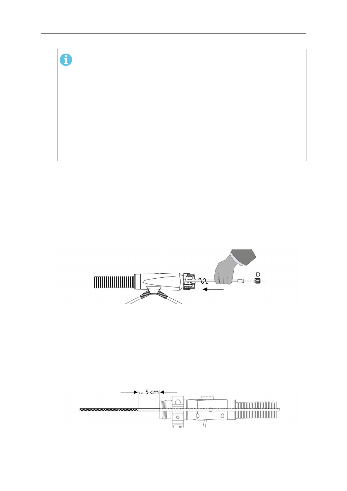
5 INSTALLATION
6. Reinstall the wire guide and attach the sleeve nut (2).
ПРИМЕЧАНИЕ!
For hollow wrist systems where Infiniturn and Helix cable assemblies are
used, wire guides should be installed without tension so that the ends of the
liners may rotate freely.
Important note when using a plastic liner:
The wire channel between the drive rolls of the feeder and the central
connector of the torch must be fitted with a plastic liner. Depending on the
design of the feeder, a piece of plastic liner inserted into a brass guide tube
can be used.
During wire run-in, make sure that the wire is fed correctly into the plastic liner
of the torch. If necessary, remove the cable assembly from the feeder and
insert the wire, then reattach.
5.6.3 Installing a continuous wire guide in the cable assembly
Installing a steel liner
The wire guide is inserted through the cable assembly from the rear and reaches to the
contact tip. The following worksteps must be followed for the correct calculation of the length
(example for Euro central connector):
1. Install the torch (see section "Torch neck equipment").
2. Remove the gas nozzle and contact tip from the torch.
3. Remove the sleeve nut (D) from the Euro connector.
4. Push in the liner through the central connector and fix with the sleeve nut.
5. Cut off the liner flush with the nozzle holder. To determine the thread projection of the
contact tip, pull the liner backwards and screw in the contact tip.
6. Push the liner forwards as far as it will go to the contact tip applying light pressure on
the liner and measure the length to be shortened at the rear.
7. Now remove the liner again and cut the excess length measured off it’s front end. If
needed, grind down the burred edges. Make sure the inner opening of the liner is not
obstructed by the cut wire end.
8. The insulation of the liner must be removed after cutting off in the front area, such that
the insulation protrudes out of the RM2 flange by approx. 5 cm. For this, briefly
remove the torch neck.
9. Push the liner back in again and fix with the sleeve nut (D), see above. Re-install the
gas nozzle.
0463 373 101
- 54 -
© ESAB AB 2018

5 INSTALLATION
Installing a plastic liner
1. Mount the torch neck (see section "Torch neck equipment") and equip it with a gas
nozzle and contact tip.
2. Remove the sleeve nut (D) from the Euro connector.
3. Cleanly cut off the liner, slightly break the outer edges, point slightly (e.g. with a pencil
sharpener).
4. Insert the liner through the central connector into the cable assembly with fitted torch.
If it gets stuck, rotate the liner to free it and facilitate installation.
ПРИМЕЧАНИЕ!
Make sure the liner is completely inserted by rotating it and slightly pushing it
forward, until you can feel it has reached its stop.
5. Mount the nipple (B) and the O-Ring (C), move it to the right position and fix it with the
sleeve nut (D) of the Euro central connector.
6. Measure the required overlap needed inside the wire feeder cabinet and cut the liner
accordingly.
5.7 Adjust the narrow gap contact tip
The adjusting tool RT42-NG is designed for the narrow gap torch necks RT42W-NG,
RT42G-NG and RT 82W-0°NG, torches with curved narrow gap contact tip. It facilitates the
precisely repeatable and fast changing of the curved contact tip.
ПРИМЕЧАНИЕ!
The adjusting tool must be securely fastened to a stable base, in order to prevent
the position of the device in relation to the robot cannot change unintentionally. If the
exact orientation of the device is lost, the alignment of the contact tip used for the
elaboration of the welding programs can no longer be reproduced with precision.
Select a position within the operating range of the robot for orientation (alignment) of the
contact tip to the torch. Fasten the adjusting tool firmly to a base using the fastening grooves
provided for this purpose. Fastening material is not included with the adjusting tool. Select
fastening material (screws) to suit the existing conditions.
Save all motion sequences and stop positions required to change or align the wearing parts
to a separate robot program.
Before programming the welding tasks: plan at which orientation the contact tip is to stand in
relation to the torch. The torch must then be positioned in the desired rotational position and
the contact tip aligned using the adjusting device. Only then may the welding task be
programmed. If different orientations of the contact tip are required for various welding tasks,
the contact tip has to be aligned to the new position when the welding task is changed.
ВНИМАНИЕ!
The gas nozzle and the torch head become very hot during welding. Always allow
the torch to cool down before replacing wearing parts or adjusting the contact tip.
0463 373 101
- 55 -
© ESAB AB 2018

5 INSTALLATION
Adjust the contact tip
Move the robot torch to a position parallel to
the opening of the adjusting tool (2). Maintain
a sufficient distance to the work table to be
able to comfortably remove the gas nozzle.
Define this position in your robot program as
the wearing parts change position (stop
position 1).
Remove the gas nozzle by pulling it
downwards. Remove the welding wire in the
contact tip if necessary.
Loosen the counter nut (4) of the contact tip
while counter-holding the nozzle holder at the
wrench flat (3).
Unscrew the contact tip including the counter
nut from the nozzle holder and replace the
nozzle holder if necessary.
Completely screw the counter nut (4) onto the
new contact tip. Screw the contact tip
including the counter nut into the nozzle
holder.
Align the contact tip until it is parallel to the
opening of the adjusting tool. If necessary,
slightly unscrew the contact tip so that it can
be easily turned in both directions.
0463 373 101
- 56 -
© ESAB AB 2018

5 INSTALLATION
ПРИМЕЧАНИЕ!
The contact tip must be able to be
easily moved by hand in both
directions in order to enable the
threading of the adjusting tool.
Place the robot torch or contact tip directly in
front of the opening of the adjusting tool (2)
(stop position 2).
Insert it slowly from the front until it is
completely inserted into the device (stop
position 3).
The contact tip was aligned exactly in the
device during insertion. Now cautiously
tighten the counter nut (4) in this position,
while counter holding the nozzle holder at the
wrench flat.
Slowly move the robot torch out of the
adjusting gauge, return to stop position 1 and
push on the gas nozzle as far as it will go.
Allow the welding wire to run into the contact
tip and bring the robot arm into welding
position.
0463 373 101
- 57 -
© ESAB AB 2018
6 OPERATION
6 OPERATION
ОСТОРОЖНО!
Before starting the system, check the whole installation according to the
manufacturer's instructions and applicable safety regulations.
Check the following to make sure that the system has been installed correctly:
1. Are all parts securely attached (torch, torch mount, flanges, safety-off device, cable
assembly, and wire feeder cabinet)?
2. Are all media hoses connected correctly and protected from damage?
3. Is the EURO central connector or direct connector fastened tightly?
4. Is the cable assembly length correct and suitable for the installation and can the cable
rotate freely? The cable must not be bent sharply. Any risk of the cable getting caught
on another object must be eliminated.
5. Is the control cable of the safety-off circuit connected and functioning? Move torch by
hand to test (RTKSC-2 and RTKS-2 only).
6. Is the torch firmly attached and is it completely equipped?
7. Is the wire guide installed according to the manual?
8. Are all lines and tubes arranged so that they cannot be damaged or bent?
The wire run-in can now be started, either via the wire run-in pushbutton or via the wire run-in
at the feeder.
6.1 Important information for programming (hollow wrist system only)
Fast rotation of axis 6 of the robot will significantly stress the cable assembly. In certain
cases, this can lead to damage or destruction of the cable. In order to maximize the lifetime
of the cable, we strongly suggest respecting the following limitations when programming the
robot.
Position of axis 5 Max. rotational speed of axis 6
0 – 60° 100 % (no limitations)
60° – 80° 300°/sec (approximately 50 % of max. robot speed)
> 80° 120°/sec (approximately 20 % of max. robot speed)
ПРИМЕЧАНИЕ!
The above values are only indications. For information on the exact rotational speed
limits, refer to the individual robot manual or contact the robot supplier.
To reposition the torch quickly, the robot arm may have to be slightly extended first to achieve
a bending angle of max. 60° of axis 5. In this position, the maximum available rotation speed
of axis 6 can be used.
When using the ESAB Helix cable assembly, the max. rotation of ±270° from the neutral
position must not be exceeded.
0463 373 101
- 58 -
© ESAB AB 2018
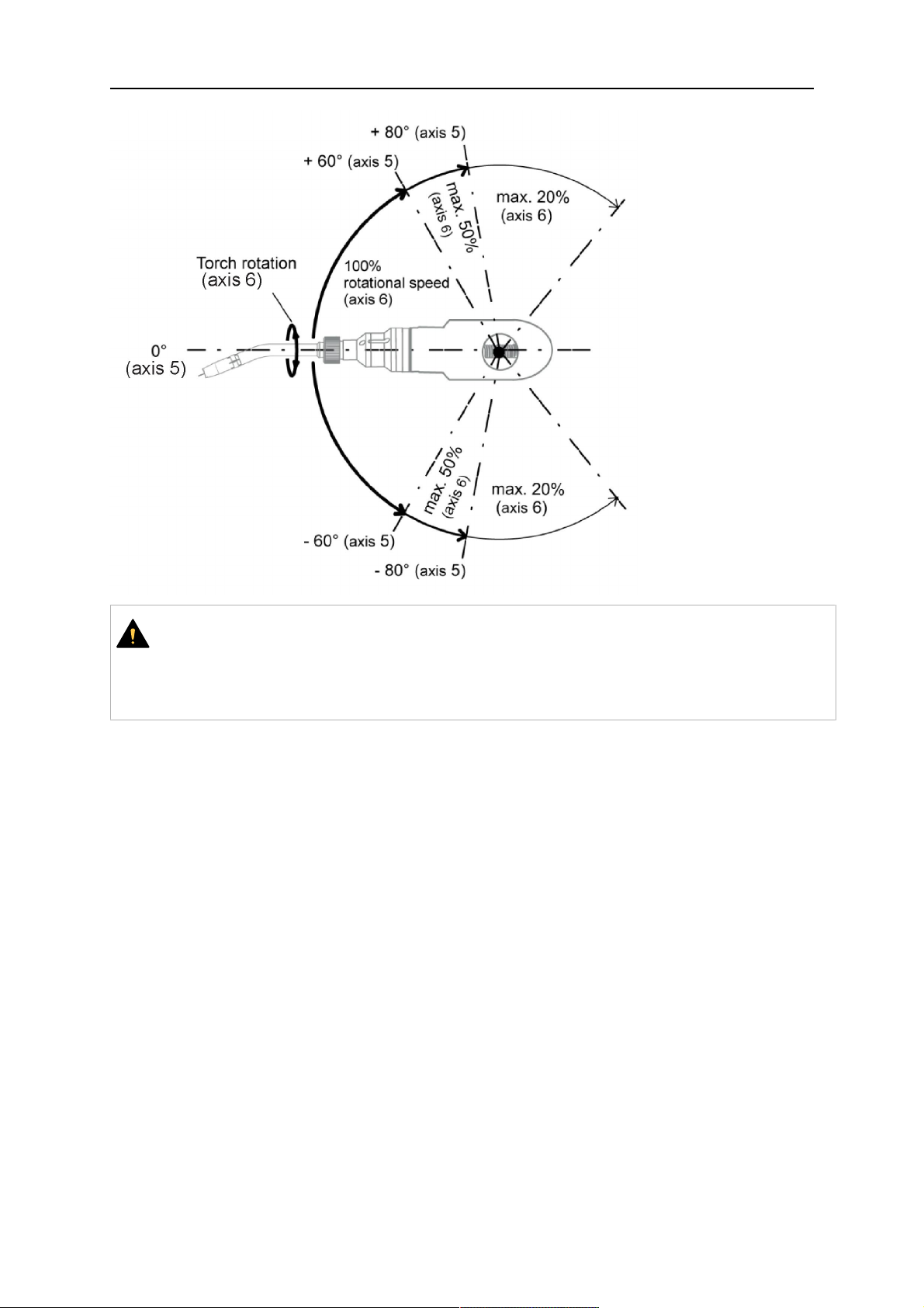
6 OPERATION
ОСТОРОЖНО!
While axis 5 is bent more than 60°, the rotational speed of the torch around axis 6
must be limited, see table above.
Otherwise, the cable assembly may be damaged.
0463 373 101
- 59 -
© ESAB AB 2018

7 СЕРВИСНОЕ И ТЕХНИЧЕСКОЕ ОБСЛУЖИВАНИЕ
7 СЕРВИСНОЕ И ТЕХНИЧЕСКОЕ ОБСЛУЖИВАНИЕ
ВНИМАНИЕ!
Перед проведением технического обслуживания системы необходимо
отключить основной источник питания установки. Соблюдайте требования
техники безопасности, указанные в данном руководстве!
Запрещено использовать поврежденные горелки или кабельные сборки!
Устранение обнаруженных дефектов должен выполнять квалифицированный
персонал перед дальнейшей эксплуатацией оборудования.
ВНИМАНИЕ!
Опасность ожогов! Газовое сопло и головка горелки существенно нагреваются
по время сварки. Горелка должна остыть перед проведением технического
обслуживания.
ВНИМАНИЕ!
Во избежание травм или повреждения оборудования следуйте приведенным
ниже инструкциям.
1. Ремонт держателя горелки RT KSC-2 или RT FLC-2, механизма
аварийного отключения RT KS-2, кабельной сборки или муфты среды
Infiniturn должна выполнять только служба сервисной поддержки
ESAB.
2. Запрещается вскрывать муфту среды Infiniturn. Она не содержит
деталей, подлежащих обслуживанию пользователем, и будет
разрушена при разборке.
3. Запрещается разбирать RT KSC-2 или RT KS-2. Это подпружиненный
механизм. Неправильное обращение может привести к тяжелой
травме.
7.1 Обязательные проверки и действия
Перед каждым использованием:
• Проверьте горелку, контактную насадку, газовое сопло, подающую
направляющую шейки, кабели и общее оборудование на наличие общих
повреждений.
ПРИМЕЧАНИЕ!
Чтобы сократить время простоя, рекомендуется переключаться между двумя
шейками горелки, всегда иметь под рукой сменную шейку горелки, готовую к
использованию.
Каждые 8 часов работы (в зависимости от применения):
• Сменить контактную насадку.
Ежедневно:
• Вручную выполните функциональную проверку механизма аварийного
отключения.
• Выполните осмотр на наличие повреждений, например изгибов или трещин.
• Проверьте правильность положения устройства подачи проволоки. Кабельная
сборка не должна быть слишком натянута или иметь провисание.
0463 373 101
- 60 -
© ESAB AB 2018

7 СЕРВИСНОЕ И ТЕХНИЧЕСКОЕ ОБСЛУЖИВАНИЕ
• Осмотрите штуцеры среды и муфту среды Infiniturn на наличие утечек.
• Выполните очистку и техническое обслуживание горелки в соответствии с
руководством по эксплуатации горелки.
Каждые 40 часов работы (в зависимости от применения):
• Замените направляющие проволоки.
• Замените направляющие шейки.
Еженедельно или по мере необходимости в зависимости от использования:
• Снимите направляющую проволоки и проверьте на наличие износа и отложений
грязи. При необходимости замените.
Ежемесячно или чаще при интенсивном использовании (т.е. более 8 часов в
день):
• Продувайте канал направляющей для проволоки сжатым воздухом (удалите
контактную насадку и направляющую проволоки).
• Убедитесь, что все винты затянуты.
• Проверяйте все соединения и шланги на отсутствие повреждений.
• Замена после 250кг сварочной проволоки.
Для безопасной эксплуатации системы обученный персонал должен устранить
повреждение электрической изоляции.
0463 373 101
- 61 -
© ESAB AB 2018

8 ПОИСК И УСТРАНЕНИЕ НЕИСПРАВНОСТЕЙ
8 ПОИСК И УСТРАНЕНИЕ НЕИСПРАВНОСТЕЙ
Неисправность Возможная причина Действие
Проволока не
подается
Сварочная проволока не была
выпрямлена перед подачей в
кабельную сборку
Горелка и кабельная сборка не
соответствуют диаметру и
материалу проволоки
Направляющая для проволоки
неправильно вставлена в
кабельную сборку
При необходимости снова
вытяните проволоку, обрежьте
конец и удалите заусенцы, после
чего выпрямите первые 10см
проволоки. Затем снова
заправьте проволоку в кабель в
сборе.
Проверьте направляющую
проволоки (кабель в сборе и
шейка горелки) и контактную
насадку.
Немного вытяните
направляющую проволоки из
разъема Euro. При установке
направляющей проволоки вы
должны почувствовать, что
последние сантиметры проволоки
попали в наконечник
направляющей в месте
сопряжения горелки. Если этого
не произошло, проволока
недостаточно длинная и
установлена не полностью.
Горелка
сильно
нагревается
Контактная насадка засорена
проволокой
Направляющая проволоки
изношена
Подача проволоки затруднена
грязью и мусором в горелке
Замените контактную насадку
и/или направляющую для
проволоки, выполните продувку
шейки горелки, направляющей
для проволоки и провод
направляющей при помощи
сжатого воздуха.
Неправильно затянута контактная
насадка или держатель насадки
Используйте подходящий
инструмент для затягивания
величиной, аналогичной
затягиванию вручную.
Некорректная работа системы
охлаждения
Неправильное подключение
системы охлаждения.
Проверьте подачу воды, чистоту
и уровень наполнения.
Проверьте соединения (подачу и
слив воды).
Чрезмерная нагрузка горелки Проверьте соблюдение
технических требований, при
необходимости выберите другой
тип.
Неисправность кабеля в сборе Проверьте кабели, трубы и
соединения.
0463 373 101
- 62 -
© ESAB AB 2018

8 ПОИСК И УСТРАНЕНИЕ НЕИСПРАВНОСТЕЙ
Неисправность Возможная причина Действие
Проблемы с
подачей
проволоки
Подача
проволоки
прекращается
во время
сварки
Износ контактной насадки Замените контактную насадку.
Износ/загрязнение
проволокопровода
Проверьте направляющую;
продуйте. При необходимости
замените.
Используемые расходные
материалы не подходят для
Сверьтесь с перечнем запасных
деталей.
диаметра или материала
проволоки
Нарушение настроек блока
подачи проволоки
Проверьте ролики подачи
проволоки, контактное давление
и тормоз барабана.
Кабельная сборка изогнута или
проложена со слишком малым
радиусом
Проверьте кабель в сборе на
отсутствие повреждений. Легко
ли вставляется направляющая?
Выполните установку в
соответствии с инструкциями. См.
раздел "Установка кабельной
сборки".
Проволока имеет загрязнения Используйте сукно для очистки.
В барабане закончилась
проволока
Убедитесь в достаточном
количестве сварочной проволоки
в барабане блока подачи
проволоки.
Застревание проволоки в
кабельной сборке
Проверьте скорость подачи
проволоки (возможно, она
слишком высокая), проверьте
контактную насадку на наличие
загрязнений/засора, при
необходимости очистите или
замените контактный наконечник.
Сварочный
процесс
прерывается
0463 373 101
Проволока приварилась к
контактной насадке или
произошел износ контактной
насадки
Сработал механизм аварийного
отключения.
- 63 -
Замените контактную насадку.
Найдите и устраните проблему,
вызвавшую срабатывание
механизма. Проверьте
надежность контакта цепи
управления.
© ESAB AB 2018

8 ПОИСК И УСТРАНЕНИЕ НЕИСПРАВНОСТЕЙ
Неисправность Возможная причина Действие
Наличие пор в
сварном шве
Нестабильност
ь арки
Материал, налипший в
результате разбрызгивания, стал
причиной завихрений газа
Недостаточный или чрезмерный
Очистите головку горелки,
используйте газовый диффузор /
средство защиты от брызг.
Измерьте скорость подачи газа.
расход газа в горелке
Некорректная подача газа Проверьте скорость подачи газа и
убедитесь в отсутствии утечек.
Намокание или загрязнение
проволоки или детали
Проверьте проволоку и деталь,
используйте меньшее количество
жидкости или выберите другую
жидкость для уменьшения
разбрызгивания.
Износ контактной насадки Замените контактную насадку.
Неверные параметры сварки Проверьте настройки сварочного
оборудования.
Некачественные электрические
соединения в цепи
Проверьте все электрические
соединения (в т.ч. кабель
заземления) между горелкой и
источником питания или
жесткость фиксации
свариваемого материала.
0463 373 101
- 64 -
© ESAB AB 2018
9 ЗАКАЗ ЗАПАСНЫХ ЧАСТЕЙ
9 ЗАКАЗ ЗАПАСНЫХ ЧАСТЕЙ
ОСТОРОЖНО!
Работы по ремонту и электрическому монтажу должны выполняться
квалифицированным техником ESAB по обслуживанию оборудования.
Используйте только оригинальные запасные и изнашиваемые части ESAB.
Горелки ESAB RT: RTKS-2, RTFL-2, RT-KSC-2, RT-FLC-2, RT42, RT52, RT62, RT72,
RT82, RT42-NG и RT82WNG разработаны и испытаны в соответствии с
международными и европейскими стандартами IEC/EN 60974-7. Обслуживающая
организация, выполнившая техническое обслуживание или ремонтные работы,
обязана обеспечить дальнейшее соответствие параметров изделия требованиям
указанного стандарта.
Дополнительные и изнашиваемые детали можно заказать через ближайшего дилера
компании ESAB, см. esab.com. При заказе указывайте тип изделия, серийный номер и
номер запасной части по перечню запасных частей. Это упростит отправку и обеспечит
ее правильность.
0463 373 101
- 65 -
© ESAB AB 2018

ESAB AB, Lindholmsallén 9, Box 8004, 402 77 Gothenburg, Sweden, Phone +46 (0) 31 50 90 00
http://manuals.esab.com
For contact information visit esab.com
 Loading...