


RT Robo Welding Torch System
RTKS-2, RTFL-2, KSC-2, FLC-2, RT42, RT52,
RT62, RT72, RT82, RT42-NG, RT82WNG
Manual de instrucțiuni
0463 373 101 RO 20181227


CUPRINS
1
SIGURANŢĂ ................................................................................................ 5
1.1 Semnificaţia simbolurilor ...................................................................... 5
1.2 Măsuri de siguranţă ............................................................................... 5
2
GARANŢIE................................................................................................... 9
2.1 Condiţiile utilizării prevăzute................................................................. 9
3
INTRODUCERE ........................................................................................... 10
3.1 Prezentarea generală a sistemelor cu arzător de sudură................... 11
4
DATE TEHNICE ........................................................................................... 13
4.1 Gâtul arzătorului de sudură................................................................... 13
4.2 Tensiune nominală ................................................................................. 14
4.2.1 Limitele circuitului de răcire .................................................................. 15
4.3 Montajul arzătorului ............................................................................... 15
4.3.1 Montajele arzătorului pentru sistemul RT standard .............................. 15
4.3.1.1 Mecanismul safety-off RTKS-2......................................................... 16
4.3.1.2 Flanșa intermediară RTFL-2............................................................. 16
4.3.2 Montajele arzătorului pentru sistemul de articulație hollow wrist.......... 17
4.3.2.1 Montajul arzătorului RTKSC-2 G/W cu mecanism safety-off............ 18
4.3.2.2 Montajul arzătorului rigid RTFLC-2 G/W .......................................... 19
4.4 Flanşe adaptoare.................................................................................... 20
4.5 Ansamblurile de cabluri......................................................................... 20
4.5.1 Ansambluri de cabluri pentru sistemul RT standard............................. 20
4.5.2 Ansambluri de cabluri pentru sistemele hollow wrist............................ 21
5
INSTALLATION............................................................................................ 23
5.1 RTKS-2 standard arm installation........................................................ 23
5.1.1 RTKS-2 safety-off mechanism............................................................. 23
5.1.1.1 Torch installation with adjustable mount............................................ 24
5.1.2 Standard arm cable assembly for KS-2 and FL-2 ................................ 26
5.1.3 RTKS-2 wire feeder connection........................................................... 27
5.1.4 RTKS-2 electrical connections ............................................................ 28
5.1.4.1 RTKS-2 safety-off mechanism connection ....................................... 28
5.1.5 RTKS-2 Torch installation .................................................................... 29
5.2 RTFL-2 standard arm installation ........................................................ 30
5.2.1 RTFL-2 rigid mount.............................................................................. 30
5.2.2 RTFL-2 torch installation ..................................................................... 32
5.3 RTKSC-2 hollow wrist system installation.......................................... 32
5.3.1 RTKSC-2 mount with safety off mechanism........................................ 32
5.3.2 Mounting the cable assembly............................................................... 33
5.3.2.1 RTKSC-2 feeder cabinet connections .............................................. 34
5.3.3 RTKSC-2 cable assembly ................................................................... 36
5.3.3.1 RTKSC-2 cable assembly installation .............................................. 36
5.3.3.2 RTKSC-2 electrical connections....................................................... 39
0463 373 101 © ESAB AB 2018

CUPRINS
5.3.4 RTKSC-2 torch installation .................................................................. 40
5.4 RTFLC-2 installation.............................................................................. 41
5.4.1 RTFLC-2 mount................................................................................... 41
5.4.2 RTFLC-2 wire feeder connection......................................................... 41
5.4.2.1 Feeding through the robot arm.......................................................... 41
5.4.2.2 RTFLC-2 feeder cabinet connections............................................... 42
5.4.3 RTFLC-2 cable assembly .................................................................... 44
5.4.3.1 RTFLC-2 cable assembly installation ............................................... 44
5.4.4 RTFLC-2 electrical connections .......................................................... 47
5.4.4.1 RTFLC-2 hollow wrist system with Infiniturn cable assembly........... 47
5.4.4.2 RTFLC-2 hollow wrist system with Helix cable assembly................. 48
5.5 Torch installation.................................................................................... 48
5.5.1 Torch neck equipment .......................................................................... 48
5.5.2 Aristo RT torch neck installation ........................................................... 49
5.6 Installing the wire guide for standard and hollow Wrist arm ............. 50
5.6.1 Installing the neck liner......................................................................... 50
5.6.2 Installing a split wire guide in the cable assembly................................ 51
5.6.3 Installing a continuous wire guide in the cable assembly..................... 53
5.7 Adjust the narrow gap contact tip ........................................................ 54
6
OPERATION ................................................................................................ 57
6.1 Important information for programming (hollow wrist system only) 57
7
SERVICE ŞI ÎNTREŢINERE ........................................................................ 59
7.1 Verificări și măsuri obligatorii............................................................... 59
8
DEPANARE.................................................................................................. 61
9
COMANDAREA PIESELOR DE SCHIMB................................................... 63
Sunt rezervate drepturile de a modifica specificațiile fără preaviz.
0463 373 101 © ESAB AB 2018

1 SIGURANŢĂ
1 SIGURANŢĂ
1.1 Semnificaţia simbolurilor
Aşa cum se utilizează în cadrul acestui manual: Semnifică Atenţie! Fiţi vigilent!
PERICOL!
Semnifică pericole imediate care, dacă nu sunt evitate, vor cauza vătămare
corporală imediată şi gravă sau decesul.
AVERTIZARE!
Semnifică pericole potenţiale care ar putea cauza vătămare corporală sau
decesul.
ATENȚIE!
Semnifică pericole care ar putea cauza vătămare corporală minoră.
AVERTIZARE!
Înainte de utilizare, citiţi şi înţelegeţi manualul de
utilizare şi respectaţi toate etichetele, practicile de
siguranţă ale angajatorului şi fişele cu date de securitate
(FDS-urile).
1.2 Măsuri de siguranţă
Utilizatorii echipamentului ESAB au responsabilitatea finală de a se asigura că persoanele
care lucrează sau se află în apropierea echipamentului respectă măsurile de siguranță
corespunzătoare. Măsurile de protecție trebuie să îndeplinească cerințele care se aplică
acestui tip de echipament. Pe lângă normele standard care se aplică spațiului de lucru,
trebuie respectate următoarele recomandări.
Toate lucrările trebuie să fie efectuate de către personal calificat, familiarizat complet cu
operarea echipamentului. Exploatarea incorectă a echipamentului poate să conducă la
situații periculoase care pot determina vătămarea corporală a operatorului și deteriorări ale
echipamentului.
1. Personalul care utilizează echipamentul de sudură trebuie să fie familiarizat cu:
○ exploatarea acestuia
○ amplasamentul dispozitivelor de oprire în caz de urgență
○ funcția acestuia
○ măsurile de protecție relevante
○ sudarea și tăierea sau celelalte funcții aplicabile ale echipamentului
2. Operatorul trebuie să se asigure că:
○ nici o persoană neautorizată nu staționează în zona de lucru a echipamentului
când acesta este pornit
○ nimeni nu este neprotejat la aprinderea arcului sau când se începe lucrul cu
echipamentul
3. Spațiul de lucru trebuie:
○ să fie adecvat scopului
○ să nu aibă curenți de aer
0463 373 101
- 5 -
© ESAB AB 2018

1 SIGURANŢĂ
4. Echipament individual de siguranță:
○ Purtați întotdeauna echipamentul individual de protecție recomandat, precum
ochelari de protecție, îmbrăcăminte neinflamabilă, mănuși de protecție
○ Nu purtați obiecte precum eșarfe, brățări, inele etc., care pot să se agațe sau să
cauzeze arsuri
5. Măsuri generale de protecție:
○ Asigurați-vă că este conectat sigur cablul de retur
○ Lucrările la echipamentul de înaltă tensiune trebuie efectuate numai de către
un electrician calificat
○ Echipamentul corespunzător de stingere a incendiilor trebuie să fie marcat în
mod vizibil și să fie la îndemână
○ Lubrifierea și întreținerea echipamentului nu trebuie să se efectueze în timpul
exploatării
AVERTIZARE!
Sudura și tăierea cu arc electric vă pot răni pe dvs. și pe alții. Luați măsuri de
precauție când sudați sau tăiați.
ȘOC ELECTRIC – Pericol de moarte
• Instalați și împământați unitatea în conformitate cu manualul de utilizare.
• Nu atingeţi componentele electrice sub tensiune sau electrozii cu pielea
neprotejată, mănuşi ude sau îmbrăcăminte udă.
• Izolaţi-vă faţă de lucrare şi pământ.
• Asigurați-vă că poziția dvs. de lucru este sigură
CÂMPURI ELECTRICE ŞI MAGNETICE – Pot prezenta pericol pentru
sănătate
• Sudorii cu stimulatoare cardiace trebuie să se consulte cu medicul înainte
de a efectua operaţiuni de sudare. Câmpurile electromagnetice pot
interfera cu anumite stimulatoare cardiace.
• Expunerea la câmpurile electromagnetice poate avea şi alte efecte
necunoscute asupra sănătăţii.
• Sudorii trebuie să utilizeze următoarele proceduri pentru a minimiza
expunerea la câmpurile electromagnetice:
○ Dirijaţi electrodul şi cablurile de lucru împreună pe aceeaşi parte a
corpului dvs. Fixaţi-le cu bandă atunci când este posibil. Nu staţi cu
nicio parte a corpului între cablurile de lucru şi ale arzătorului. Nu
înfăşuraţi niciodată cablurile de lucru sau ale arzătorului în jurul
corpului dvs. Menţineţi sursa de alimentare şi cablurile pentru sudură
cât mai departe posibil de corpul dvs.
○ Conectaţi cablul de sudură la piesa de lucru cât mai aproape posibil
de zona care se sudează.
FUM ȘI GAZE – Pot prezenta pericol pentru sănătate
• Ţineţi capul în afara zonei cu fum.
• Folosiţi ventilaţia, extracţia arcului sau ambele pentru a scoate vaporii şi
gazele din zona dumneavoastră de respiraţie şi spaţiul general.
0463 373 101
RAZE DE ARC ELECTRIC – Pot afecta ochii și pot arde pielea
• Protejați-vă ochii și corpul. Utilizați paravanul de sudură și geamul de
filtrare corecte și purtați îmbrăcăminte de protecție.
• Protejaţi-i pe cei din jur cu ecrane sau cortine corespunzătoare.
- 6 -
© ESAB AB 2018

1 SIGURANŢĂ
ZGOMOT – Zgomotul excesiv poate afecta auzul
Protejați-vă urechile. Utilizați căști sau alte dispozitive de protecție pentru auz.
PIESE ÎN MIŞCARE - Pot cauza vătămări
• Menţineţi toate uşile, panourile şi capacele închise şi în poziţii sigure.
Permiteţi numai persoanelor calificate să îndepărteze capacele pentru
întreţinere şi depanare, după cum este necesar. Montaţi din nou panourile
sau capacele şi închideţi uşile după finalizarea operaţiunilor de service şi
înainte de pornirea motorului.
• Opriţi motorul înainte de montarea sau conectarea unităţii.
• Ţineţi mâinile, părul, hainele largi şi uneltele departe de piesele în mişcare.
PERICOL DE INCENDIU
• Scânteile (stropii) pot cauza incendii. Asiguraţi-vă că nu există materiale
inflamabile în apropiere.
• Nu utilizaţi pentru containere închise.
FUNCȚIONARE DEFECTUOASĂ – Apelați la un expert pentru asistență în caz de
funcționare defectuoasă.
PROTEJAŢI-VĂ PE DVS. ŞI PE CEILALŢI!
ATENȚIE!
Acest produs este destinat exclusiv sudurii cu arc.
AVERTIZARE!
Nu utilizați sursa de alimentare pentru dezghețarea țevilor înghețate.
ATENȚIE!
Echipamentele din Clasa A nu sunt destinate pentru
utilizare în amplasamentele rezidențiale unde energia
electrică este furnizată de sistemul public de alimentare
de joasă tensiune. Din cauza perturbațiilor conduse și
radiate, pot exista dificultăți în asigurarea compatibilității
electromagnetice a echipamentelor din clasa A în
aceste locații.
0463 373 101
- 7 -
© ESAB AB 2018

1 SIGURANŢĂ
NOTĂ!
Predați echipamentul electronic uzat la centrul de
reciclare!
În conformitate cu prevederile Directivei Europene
2012/19/CE privind deșeurile de echipamente electrice
și electronice, precum și cu implementarea acesteia
conform legislației naționale, echipamentul electric
și/sau electronic care a atins limita maximă a duratei de
viață trebuie să fie predat la un centru de reciclare.
Ca persoană responsabilă pentru echipament, aveți
responsabilitatea de a obține informațiile despre stațiile
de colectare autorizate.
Pentru mai multe informații, contactați cel mai apropiat
distribuitor ESAB.
ESAB oferă spre achiziţionare un sortiment de accesorii pentru sudură şi echipamente
individuale de protecție. Pentru informații despre comenzi, contactați distribuitorul
dvs. local ESAB sau vizitați-ne pe site-ul nostru web.
0463 373 101
- 8 -
© ESAB AB 2018

2 GARANŢIE
2 GARANŢIE
Produsele noastre sunt verificate cu atenție înainte de a fi expediate. ESAB confirmă că
fiecare produs este lipsit de defecte de material şi manoperă la momentul livrării şi că
funcţionează în conformitate cu domeniul de utilizare.
ESAB furnizează garanţie faţă de defectele de material şi de manoperă în conformitate cu
cerinţele legale. Consumabilele sunt exceptate de la această garanţie.
Garanţia nu acoperă daune sau defecte funcţionale derivate din:
• supraîncărcarea, abuzarea sau nerespectarea domeniului de utilizare a produsului
• coliziuni sau accidente
• nerespectarea instrucțiunilor prezentate în aceste instrucţiuni de utilizare
• instalare sau asamblare inadecvată
• întreţinere insuficientă
• modificarea produsului în raport cu starea sa originală
• influenţe chimice
• uzura normală
ESAB nu îşi asumă nicio responsabilitate alta decât înlocuirea sau repararea pieselor
defecte.
2.1 Condiţiile utilizării prevăzute
1. Produsul este destinat utilizării în scop industrial și comercial și trebuie să fie utilizat
numai de către un personal instruit. Producătorul nu este răspunzător de daunele sau
accidentele care rezultă din utilizarea necorespunzătoare.
2. Sistemul de sudură robotică Aristo® RT este proiectat și produs în condiții moderne,
utilizarea acestuia fiind una fiabilă și sigură atunci când este manipulat, montat și
întreținut de către personalul instruit. Respectați instrucțiunile de montare, utilizare și
întreținere descrise în acest document.
3. Sistemul de sudură robotică Aristo® RT poate fi montat, utilizat și întreținut numai de
către personalul instruit. Respectați reglementările privind montarea, utilizarea și
întreținerea detaliate în acest manual.
4. Sistemul de sudură robotică Aristo® RT poate fi utilizat numai în scopul prevăzut de
către producător, respectând datele tehnice și împreună cu sistemele de manevrare
automate. Tipul de arzător se va selecta astfel încât să corespundă sarcinii de sudură.
5. Sistemul de sudură robotică Aristo® RT a fost proiectat pentru a fi utilizat ca un sistem
complet. Introducerea de componente provenite de la alți producători în sistem nu
este permisă.
6. RT KS-2 și RT KSC-2 pot fi utilizate numai ca mecanisme de oprire de urgență
conform specificațiilor tehnice ale acestora și în combinație cu un ansamblu de cabluri
cu braț standard RT (KS-2), Infiniturn sau Helix (KSC-2), o flanșă adaptoare ESAB,
inclusiv montajele arzătorului RT (KS-2) și un arzător de sudură Aristo RT.
7. Nu adăugați ulei sau lichide anti-împroșcare în gazul de suflare. ESAB nu asigură
rezistența chimică la aceste substanțe. ESAB recomandă utilizarea unității de
pulverizare ESAB pentru a aplica o cantitate minimă de lichid anti-împroșcare în
arzător și, prin urmare, protejează mediul.
8. Păstrați produsul uscat și protejat împotriva umidității în timpul transportului,
depozitării sau al utilizării.
9. Sistemul este proiectat pentru temperaturi ambiante care variază între 5 °C și 40 °C
(41 °F și 104 °F). În cazul în care aceste limite sunt depășite, se impune o măsură
specifică. În cazul riscului de îngheț, utilizați un agent de răcire adecvat.
0463 373 101
- 9 -
© ESAB AB 2018

3 INTRODUCERE
3 INTRODUCERE
Sistemele cu arzător de sudură RT sunt dezvoltate pentru sudura MIG/MAG complet
automată cu ajutorul roboților. Sistemele constau într-o varietate de gâturi de arzătoare
Aristo RT proiectate pentru utilizarea robotică, montajele arzătorului, ansamblurile de cabluri
optimizate pentru utilizarea robotică și funcțiile safety-off pentru a preveni deteriorarea
sistemului în caz de coliziune.
Sistemul de sudură RT standard furnizează o protecție împotriva coliziunii utilizând RTKS-2,
care este o funcționalitate safety-off mecanică acționată cu arc. Aceasta poate fi înlocuită
opțional cu RTFL-2 pentru a beneficia de funcția de detectare a coliziunii a sistemului de
comandă prin robot. Sistemul de sudură RT standard poate fi utilizat cu o varietate de tipuri
de ansambluri cablu.
Montajele arzătorului RTKSC-2 și RTFLC-2 cu ansambluri de cabluri Infiniturn sau Helix
sunt destinate utilizării în cadrul sistemelor de sudură robotică cu articulație „hollow wrist”
proiectate pentru aplicații de sudură avansate. Mecanismul safety-off prevăzut în montajul
arzătorului RTKSC-2 permite o amplă deflexie elastică a arzătorului în caz de coliziune.
Ansamblurile de cabluri Infiniturn și Helix sunt ușor de montat, asigurând un sistem extrem
de fiabil cu capacități de manevrare precisă.
În combinație cu arzătoarele de sudură robotică Aristo RT de renume, aceste părți
componente creează un sistem extrem de fiabil și durabil care necesită numai un nivel minim
de întreținere.
Manualul de instrucţiuni este inclus în livrarea montajelor arzătorului și a ansamblurilor de
cabluri.
Numerele de catalog, accesoriile disponibile, piesele de schimb, precum și piesele de
uzură ESAB se regăsesc în lista pieselor de schimb.
0463 373 101
- 10 -
© ESAB AB 2018

3 INTRODUCERE
3.1 Prezentarea generală a sistemelor cu arzător de sudură
Sistemul RT standard
Pentru o descriere detaliată, consultați
secțiunea corespunzătoare din capitolul
DATE TEHNICE:
1. Gâtul arzătorului
Consultați „Arzătorul de sudură”.
2. Ansamblu cablu
Consultați „Ansambluri de cabluri
pentru sistemul RT standard”.
3. Montajul arzătorului
Consultați „Montajele arzătorului
pentru sistemul RT standard”.
4. Mecanismul safety-off RTKS-2
Consultați secțiunea „Mecanismul
safety-off RTKS-2”.
5. Flanșa intermediară RTFL-2
Consultați „Flanșa intermediară
RTFL-2”.
6. Flanşă adaptoare (dacă este
necesar)
Consultați „Flanșe adaptoare”.
0463 373 101
- 11 -
© ESAB AB 2018

3 INTRODUCERE
Sistem de articulație hollow wrist
Pentru o descriere detaliată, consultați
secțiunea corespunzătoare din capitolul
DATE TEHNICE:
1. Gâtul arzătorului
Consultați „Arzătorul de sudură”.
2. Montajul arzătorului RTKSC-2
Consultați „Montajul arzătorului
RTKSC-2 cu mecanism safety-off”.
3. Montajul arzătorului RTFLC-2
Consultați „Montajul arzătorului rigid
RTFLC-2”.
4. Flanşă adaptoare
Consultați „Flanșe adaptoare”.
5. Ansamblul de cabluri Helix sau
Infiniturn
Consultați „Ansambluri de cabluri
pentru sistemele de articulație
hollow wrist”.
0463 373 101
- 12 -
© ESAB AB 2018

4 DATE TEHNICE
4 DATE TEHNICE
4.1 Gâtul arzătorului de sudură
Alegeți modelul de arzător conform aplicației de sudură. Luați în considerare ciclul de
funcţionare şi capacitatea, metoda de răcire şi diametrul sârmei necesare. Dacă există
cerinţe mai mari, de exemplu, cauzate de piese de prelucrat pre-încălzite sau reflectarea
ridicată a căldurii în colţuri, acestea trebuie luate în considerare, alegând un arzător de
sudură cu rezervă suficientă la puterea nominală.
Arzătoarele de sudură RT sunt destinate utilizării împreună cu sursele de alimentare pentru
sudură conforme CE pentru procesele de sudură cu gaz inert metal (MIG), sudură cu gaz
activ metal (MAG) și sudură tare MIG cu sârme rotunde comerciale. Nu utilizați arzătorul
pentru alte procese.
Utilizați arzătorul răcit cu apă RT82W pentru sudura cu arc pulsatoriu a oțelului sau sudura
cu aluminiu.
Consultați modelele de arzătoare disponibile de mai jos.
Model arzător Metodă de răcire Gaz de protecţie Valoare nominală
RT42G Răcit cu gaz CO
Răcit cu gaz 300A/100%
Răcit cu gaz Amestecat 350A/60%
Răcit cu gaz 250A/100%
RT42W Răcit cu apă CO
Răcit cu apă 420A/100%
Răcit cu apă Amestecat 350A/60%
Răcit cu apă 350A/100%
RT52G Răcit cu gaz CO
Răcit cu gaz 300A/100%
Răcit cu gaz Amestecat 350A/60%
Răcit cu gaz 250A/100%
RT52W Răcit cu apă CO
Răcit cu apă 470A/100%
Răcit cu apă Amestecat 400A/60%
Răcit cu apă 400A/100%
RT62G Răcit cu gaz CO
Răcit cu gaz 340A/100%
2
2
2
2
2
420A/60%
420A/60%
420A/60%
470A/60%
500A/60%
Răcit cu gaz Amestecat 420A/60%
Răcit cu gaz 290A/100%
RT62W Răcit cu apă CO
Răcit cu apă 530A/100%
Răcit cu apă Amestecat 450A/60%
Răcit cu apă 450A/100%
0463 373 101
- 13 -
2
530A/60%
© ESAB AB 2018

4 DATE TEHNICE
Model arzător Metodă de răcire Gaz de protecţie Valoare nominală
RT72G Răcit cu gaz CO
2
480A/60%
Răcit cu gaz 320A/100%
Răcit cu gaz Amestecat 400A/60%
Răcit cu gaz 270A/100%
RT72W Răcit cu apă CO
2
480A/60%
Răcit cu apă 430A/100%
Răcit cu apă Amestecat 480A/60%
Răcit cu apă 430A/100%
RT82W Răcit cu apă CO
2
600A/60%
Răcit cu apă 600A/100%
Răcit cu apă Amestecat 550A/60%
Răcit cu apă 550A/100%
Valorile nominale ale arzătorului și ciclul de funcţionare sunt valabile pentru un ciclu de 10
minute.
Datele tehnice sunt valabile pentru o aplicație standardizată care utilizează piese de
uzură/de schimb standard. Valoarea nominală a arzătorului este redusă atunci când se
utilizează modul de transfer al metalului cu arc pulsatoriu.
Intervale de temperatură Depozitare: -15-50°C (5-122°F)
Funcţionare: 5–40°C (41–104°F)
Gaz de suflare Max. 10 bari, furtun pentru gaz separat
Greutate totală (gâtul arzătorului,
Aproximativ 5 kg
mecanismul safety-off, montajul arzătorului și
ansamblul de cabluri de 1 m)
4.2 Tensiune nominală
Tensiune/amperaj max. permis
Sistem cu arzător de sudură complet 141 V (valoarea de vârf pentru sudură)
Circuitul de comandă safety-off RTKS-2
Butonul RTKS-2
Circuitul de comandă safety-off RTKSC-2 48 V
Utilizarea funcționalității de detectare a duzei
cu ansamblu de cabluri standard
Utilizarea funcționalității de detectare a duzei
cu ansambluri de cabluri Helix sau Infiniturn
24 V/1 A
48 V/0,1 A
50 V/5 A
(Sarcină permisă max. 1 minut la curentul
nominal)
50 V/5 A
(Sarcină permisă max. 1 minut la curentul
nominal)
Valorile nominale indicate se referă la un caz de utilizare standardizat.
Pentru valorile nominale ale ansamblului de cabluri, consultați secțiunea „Ansambluri de
cabluri”.
0463 373 101
- 14 -
© ESAB AB 2018

4 DATE TEHNICE
4.2.1 Limitele circuitului de răcire
Valabile numai pentru versiunea răcită cu apă.
Debitul min. al apei: 1,0 l/min (1,1 sferturi/min)
Presiunea min. a apei: 2,5 bari (36,3 PSI)
Presiunea max. a apei: 3,5 bari (50,8 PSI)
Temperatura de admisie: Max. 40 °C (104 °F)
Temperatura de retur: Max. 60 °C (140 °F)
Capacitate de răcire: Min. 1000 W, în funcție de aplicație
ATENȚIE!
Temperaturile de retur mai mari de 60 °C (140 °F) pot cauza deteriorarea sau
distrugerea ansamblului de cabluri.
4.3 Montajul arzătorului
Tipul de montaj al arzătorului necesar depinde de proiectarea sistemului cu arzător de
sudură RT și de alegerea dispozitivelor safety-off, consultați secțiunea „Prezentarea generală
a sistemelor cu arzător de sudură”.
Componentă Greutate aproximativă
Montajul arzătorului (pentru sistemul
0,43 kg
standard)
Mecanismul safety-off RTKS-2 (pentru
0,85 kg
sistemul standard)
Flanșa intermediară RTFL-2 (pentru sistemul
0,35 kg
standard)
Montajul arzătorului RTKSC-2 (pentru
1,90 kg
sistemul de articulație hollow wrist)
Montajul arzătorului rigid RTFLC-2 (pentru
1,22 kg
sistemul de articulație hollow wrist)
Arzător de sudură cu robot 0,66 kg
4.3.1 Montajele arzătorului pentru sistemul RT standard
Pentru sistemele RT standard, montajul arzătorului este instalat pe mecanismul safety-off
RTKS-2 (alternativ, pe flanșa intermediară RTFL-2), fixând ansamblul de cabluri și gâtul
arzătorului racordat.
Selectați montajul arzătorului în funcție de tipul de arzător și geometria acestuia. Se pot
utiliza diverse tipuri de montaje. Consultați lista pieselor de schimb pentru montajele
arzătorului disponibile pentru sistemul RT standard.
0463 373 101
- 15 -
© ESAB AB 2018

4 DATE TEHNICE
Montajul arzătorului pentru roboții cu braț standard
4.3.1.1 Mecanismul safety-off RTKS-2
Mecanismul de siguranță RTKS-2 este un dispozitiv susținut cu arc care protejează robotul
și sistemul cu arzător în cazul unei coliziuni.
NOTĂ!
Nu dezasamblați sistemul RTKS-2.
4.3.1.2 Flanșa intermediară RTFL-2
Flanșa intermediară rigidă RTFL-2 poate fi utilizată în schimbul sistemului RTKS-2 dacă
robotul este prevăzut cu un sistem electronic de detectare a coliziunii.
0463 373 101
- 16 -
© ESAB AB 2018

4 DATE TEHNICE
4.3.2 Montajele arzătorului pentru sistemul de articulație hollow wrist
În cazul sistemului de articulație hollow wrist, gâturile arzătoarelor de sudură Aristo RT sunt
racordate la montajul arzătorului KSC-2 sau FLC-2.
Montajul arzătorului RTKSC-2 permite o deflexie elastică a arzătorului în cazul unei coliziuni.
În același timp se deschide un contact electric care transmite dispozitivului de comandă a
robotului să se oprească. După resetarea erorii, geometria inițială și punctatorul de centrare
(TCP) ale arzătorului vor fi obținute cu o precizie ridicată. Sistemul funcționează pur și simplu
mecanic și este acționat cu arc.
Montajul arzătorului RTFLC-2 nu este prevăzut cu funcția safety-off încorporată.
Pentru sistemele de articulație hollow wrist se recomandă RTKSC-2 G/W (alternativ,
RTFLC-2 G/W). Acest montaj al arzătorului poate fi utilizat cu arzătoarele răcite cu gaz și
arzătoarele răcite cu apă, seria Aristo RT.
RTKSC-2 G/W RTFLC-2 G/W
Principiul de funcționare a
Mecanic Nu este cazul (montaj rigid)
mecanismului safety-off
Forță de eliberare axială (Fz) 650 N Nu este cazul (montaj rigid)
Eliberare cuplu pe axa
24 Nm Nu este cazul (montaj rigid)
transversală (Mx)
Resetare după eliberare Automat Nu este cazul (montaj rigid)
Repetabilitate Lateral ± 0,1 mm la TCP al
Nu este cazul (montaj rigid)
unui arzător Aristo RT
standard
Deflexie max. Aprox. ± 8° Nu este cazul (montaj rigid)
Comutator de siguranţă Închis normal
Nu este cazul (montaj rigid)
Sarcină electrică max. 48 V/1
A
0463 373 101
- 17 -
© ESAB AB 2018

4 DATE TEHNICE
Circuit de comandă electrică
pentru funcția de detectare a
duzei
Valoare nominală:
• Pentru ansamblurile de
cabluri Helix: max. 50 V
c.c./5 A, max. 1 minut
După detectarea unui
contact, decuplați rapid
tensiunea de detectare.
• Pentru ansamblurile de
cabluri Infiniturn, funcția
de detectare a duzei are
o funcționalitate limitată.
Valoare nominală:
• Pentru ansamblurile de
cabluri Helix: max. 50 V
c.c./5 A, max. 1 minut
• Pentru ansamblurile de
cabluri Infiniturn: max.
50 V c.c./1 A, max. 1
minut
După detectarea unui contact,
decuplați rapid tensiunea de
detectare.
Contactați ESAB pentru
o investigație detaliată a
soluțiilor posibile în
aplicația dvs.
Tensiune nominală Tensiunea maximă permisă
pentru circuitul de comandă
safety-off: 48 V.
4.3.2.1 Montajul arzătorului RTKSC-2 G/W cu mecanism safety-off
Elem
Descriere Funcţie
ent
1 Suport pentru gâtul arzătorului Interfața arzătorului Aristo RT
2 Capac RTKSC-2 Ansamblu de cabluri și interfețele arzătorului
3 Carcasă mulată din cauciuc Protecție pentru mecanismul safety-off
4 Corp principal RTKSC-2 Permite o deflexie mecanică în timpul unei coliziuni
0463 373 101
- 18 -
© ESAB AB 2018

4 DATE TEHNICE
Elem
Descriere Funcţie
ent
5 Flanşă adaptoare Izolarea interfeței de articulația robotului (trebuie să
corespundă unui anumit robot)
6 Știft de blocare Pentru o aliniere precisă cu flanșa adaptoare
7 Conector pentru cablul de
comandă
Conexiune electrică pentru semnalizarea coliziunii și
funcția de detectare a duzei
8 Micro-comutator Senzor pentru detectarea coliziunii
4.3.2.2 Montajul arzătorului rigid RTFLC-2 G/W
Elem
Descriere Funcţie
ent
1 Suport pentru gâtul arzătorului Interfața arzătorului Aristo RT
2 Capac RTFLC-2 Ansamblu de cabluri și interfețele arzătorului
3 Corp principal RTFLC-2 Permite o deflexie mecanică în timpul unei coliziuni
4 Știft de blocare Pentru o aliniere precisă cu flanșa adaptoare
5 Flanşă adaptoare Izolarea interfeței de articulația robotului (trebuie să
corespundă unui anumit robot)
6 Conector pentru cablul de
comandă (3 poli)
0463 373 101
Conexiune electrică pentru funcția de detectare a
duzei (dacă este cazul)
- 19 -
© ESAB AB 2018

4 DATE TEHNICE
4.4 Flanşe adaptoare
Alegeți flanșa adaptoare necesară pentru montarea pe brațul robotului, în funcție de tipul de
robot. Flanşele adaptoare sunt disponibile pentru toate sistemele standard și de articulație
hollow wrist adecvate, consultați lista pieselor de schimb.
4.5 Ansamblurile de cabluri
Conectarea la alimentatorul de sârmă se realizează prin intermediul ansamblului de cabluri,
versiunile disponibile care depind, în principal, de proiectarea sistemului și mediile de răcire
(gaz sau apă), consultați lista pieselor de schimb.
Valorile nominale sunt valabile pentru cabluri cu lungimi cuprinse între 1 şi 5 m.
Ansamblu de cabluri
Infiniturn Helix
standard
Valoare nominală
(ciclu de 10 min.)
Răcit cu gaz (amestec
de gaze)
Valoare nominală
(ciclu de 10 min.)
Max. 500 A/60 % ciclu
de funcţionare
Max. 350 A/100 %
ciclu de funcţionare
Max. 600 A/100 %
ciclu de funcţionare
Max. 400 A/60 % ciclu
de funcţionare
Max. 320 A/100 %
ciclu de funcţionare
Max. 550 A/100 %
ciclu de funcţionare
Răcit cu apă
Interval de rotire Capacitate limitată de
rotire
Greutate
Răcit cu gaz
Greutate
Răcit cu apă
Lungime de 1,2 m:
2,35 kg
Lungime de 1,2 m:
2,35 kg
Capacitate nelimitată
de rotire
Lungime de 1,0 m:
2,0 kg
Lungime de 1,0 m:
2,0 kg
4.5.1 Ansambluri de cabluri pentru sistemul RT standard
Max. 400 A/60 % ciclu
de funcţionare
Max. 320 A/100 %
ciclu de funcţionare
Max. 550 A/100 %
ciclu de funcţionare
± 270° din poziția
neutră
Lungime de 1,0 m:
2,0 kg
Lungime de 1,0 m:
2,0 kg
0463 373 101
- 20 -
© ESAB AB 2018
4 DATE TEHNICE
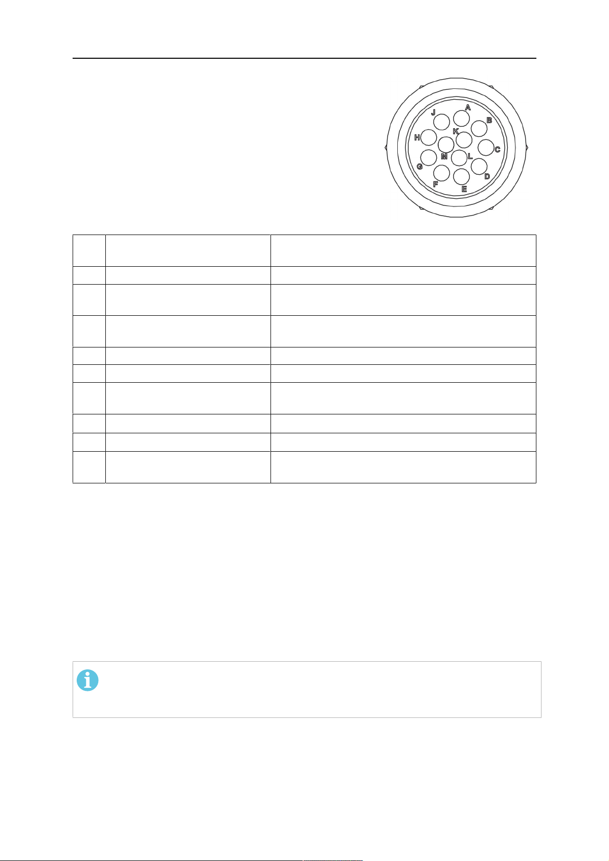
Pinii conectorului Burndy
A. Duză pentru gaz cu simț
tactil
C. Senzor de coliziune
F. 0V
G. + Tensiune motor
H. - Tensiune motor
D. Senzor de coliziune
E. Comandă prin închideri
succesive rapide
Elem
Descriere Funcţie
ent
1 Flanșă pentru susținerea gâtului Interfață arzător
2 Capac de protecție Protejează ansamblul de cabluri împotriva
deteriorărilor
3 Conector Burndy, 12 poli Conexiune electrică între sistemul safety-off și
alimentatorul de sârmă
4 Cablu de comandă Pentru KS-2 (sistem safety-off și buton)
5 Conector EURO Conectarea alimentatorului de sârmă
6 Furtun de suflare (capac negru) Pentru curățarea arzătorului cu aer comprimat după
ciclul de curățare
7 Admisie apă (capac albastru)
8 Retur apă (capac roșu)
Admisie apă pentru răcirea arzătorului
Retur apă pentru apa caldă din arzător
1)
1)
9 Mufa cablului de comandă
pentru mecanismul safety-off
1)
Numai sistemele cu arzătoare răcite cu apă
Conexiune electrică cu RTKS-2 pentru funcția de
semnalizare safety-off și de detectare a duzei
4.5.2 Ansambluri de cabluri pentru sistemele hollow wrist
Ansamblurile de cabluri Infiniturn permit rotirea nelimitată a arzătorului în ambele direcții. În
același timp se transferă lichidul de răcire, gazul de protecție, aerul pentru suflare, puterea
de alimentare pentru sudură și semnalul de la mecanismul safety-off.
Ansamblul de cabluri Helix este proiectat pentru un interval de rotire de ±270° din poziția
neutră. Acesta poate fi utilizat pentru sarcinile de sudură care nu necesită o rotire nelimitată.
Ansamblurile de cabluri Infiniturn sunt disponibile în versiunile răcite cu gaz și cu apă.
Ansamblurile de cabluri Helix pot fi utilizate în mod universal pentru aplicații răcite cu gaz sau
cu apă.
NOTĂ!
Nu conectați un ansamblu de cabluri Helix utilizat cu un gât de arzător răcit cu gaz
la un sistem de răcire cu apă.
0463 373 101
- 21 -
© ESAB AB 2018

4 DATE TEHNICE
Elem
Descriere Funcţie
ent
1 Flanșă Interfața montajului arzătorului RTKSC-2/RTFLC-2
2 Știft de blocare Stabilește orientarea corectă a cuplajului
3 Mufa cablului de comandă Conexiune electrică la RTKSC-2 pentru funcția de
semnalizare safety-off și de detectare a duzei (dacă
este cazul)
4 Conector EURO Conectarea alimentatorului de sârmă
5 Cablu de comandă Conexiune electrică pentru funcția de semnalizare
safety-off de la (RTKSC-2) și de detectare a duzei
(detectarea duzei este standard pentru Helix, dar nu
și pentru Infiniturn)
6 Retur apă (capac roșu) Retur apă pentru apa caldă din arzător
7 Admisie apă (capac albastru) Admisie apă pentru răcirea arzătorului
8 Furtun de suflare (capac negru) Pentru curățarea arzătorului cu aer comprimat după
sudură
9 Cuplajul mediului Cuplaj rotativ nelimitat la transferul mediului
10 Capac de protecție Protejează ansamblul de cabluri împotriva
deteriorărilor
0463 373 101
- 22 -
© ESAB AB 2018

5 INSTALLATION
5 INSTALLATION
AVERTIZARE!
For your own safety, make sure that the robot is either in standby or power-less
state before doing maintenance work in the moving radius of the robot.
Follow the assembly instructions exactly. Pay attention during assembly that the cables are
not damaged. Damaged cables can lead to a short circuit, which may damage the electronics
of the robot or the welding torch.
Use only original ESAB components that have been specially developed for this purpose.
Only then the correct functioning of the whole welding torch system can be guaranteed.
5.1 RTKS-2 standard arm installation
5.1.1 RTKS-2 safety-off mechanism
1. Dismount the insulation flange (10) from the RTKS-2 (11) by removing the screws
(12).
2. Position the insulation flange (10) with the index pin on the robot arm and fix it with the
screws (20) included.
The insulation flange (10) is directly compatible with robots with tool flange according
to DIN ISO 9409-1-A40 (diameter 40mm, 4×M6). If the insulation flange (10) does
not fit, use an adapter flange (21).
NOTĂ!
Ensure that the index pin is located correctly. The maximum torque of 1.2Nm
(10.5in.lb) must be observed for the fastening of the adapter flange screws.
Prevent self-loosening of the screws by using suitable thread locking
measures.
3. Mount the RTKS-2 the back on the insulation flange (10).
0463 373 101
- 23 -
© ESAB AB 2018

5 INSTALLATION
4. Position the mount on the RTKS-2 and carefully insert the cylindrical pins (14) into the
holes provided. Take the position of the torch into account. Two mounting positions
may be potentially possible.
5. Screw the mount evenly using the enclosed cylinder screws with hexagon socket (12).
NOTĂ!
The maximum tightening torque for the cylinder screw (5) is 6Nm (53in.lb)
and the property class category is 8.8.
12 - Cylinder screw with hexagon socket
M6DIN912 (length of the screw depending
on the torch mount)
14 - Cylindrical pins Ø4×20
5.1.1.1 Torch installation with adjustable mount
Torch mounts with a central clamping assembly can only be fastened on the journal of the
mounting flange. For this, the mounting flange must be fastened first.
1. If applicable, carefully press the cylindrical pins (1) into the corresponding holes in the
mounting flange. The pins should protrude by approximately 5 mm (0.2 in.).
2. Position the mount on the safety-off mechanism RTKS-2 and carefully insert the
cylindrical pins (1) into the holes provided. In doing so, take the later position of the
torch into account. Two mounting positions may be potentially possible.
3. Then screw down the mounting flange evenly using the enclosed cylinder screws with
hexagon socket (2).
NOTĂ!
The maximum tightening torque for the cylinder screw (2) is 7.1 Nm (62.8
in.lb) and the property class category is 8.8.
0463 373 101
- 24 -
© ESAB AB 2018

5 INSTALLATION
4. Unscrew the axial cylinder screw with hexagon socket (4) out of the mounting flange
together with the washer (3).
1 - Cylindrical pins Ø4×14 3 - Washer Ø9 mm
2 - Cylinder screw with hexagon socket
M6×16
4 - Axial cylinder screw with hexagon
socket M8×16
5. Place the torch mount (5) onto the journal (6) of the mounting flange, paying attention
while doing so to the exact alignment of the feather key (7) and the corresponding
groove (7a).
6. Insert the clamping mandrel (8) into the lateral hole (see illustration) and position it so
that the mating surfaces (9a) of the clamping mandrel rest on the mating surface (9) of
the journal.
0463 373 101
- 25 -
© ESAB AB 2018

5 INSTALLATION
7. Fix the clamping mandrel from the opposite side using the M6 cylinder screw with
hexagon socket (10) and the Ø22 mm washer (11).
8. Screw the axial cylinder screw (4) with the Ø9 mm washer (3) into the mounting flange
and tighten firmly.
3 - Washer Ø9 mm 8 - Clamping mandrel
4 - Axial cylinder screw with hexagon
9 - Mating surface of mounting flange
socket M8×16
5 - Torch mount 9a - Mating surfaces of clamping mandrel
6 - Mounting flange journal 10 - Cylinder screw with hexagon socket
M6×30
7 Feather key 11 - Washer Ø22×6.4 mm
7a - Groove for feather key
5.1.2 Standard arm cable assembly for KS-2 and FL-2
The cable assembly must be aligned to the intended use in length and design. The type of
cooling for the torch and the cable assembly must be the same (either gas or water cooled
respectively). In order to prevent damage to the torch system and other components, it is
imperative to observe the following instructions.
0463 373 101
- 26 -
© ESAB AB 2018

5 INSTALLATION
ATENȚIE!
• Coordinate the length and design of the cable assembly to suit the range of
action of the robot.
• Do not bend, compress or overstretch the cable assembly.
• Fix the cable assembly such that is can be moved freely and cannot become
entangled.
• Any additional holding devices possibly installed, for example a balancer,
must not crush or bend the cable assembly.
• Extreme turning movements must be avoided in which the cable assembly
may become twisted.
• Chafing on the robot or other objects must be excluded.
1. Unscrew the cylinder screws (1) and lift off the top section (2) of the torch mount.
2. Insert the feather key (4) into the recess of the neck support flange (3) from below.
3. Align the neck support flange (3) including the feather key (4) to the groove (5) of the
torch mount and push into the groove right up to the stop of the flange.
4. Hold the cable assembly in this position and simultaneously place the top section (2)
back onto the torch mount. First screw both cylinder screws (1) loosely in to about the
same length, then tighten alternately. The top section (2) of the mount should have an
even gap to the bottom section.
The front part of the cable assembly is directly clamped into the torch mount (see
illustration below).
1 - Cylinder screws 4 - Feather key
2 - Torch mount top section 5 - Groove for feather key
3 - Neck support flange
5.1.3 RTKS-2 wire feeder connection
In order to be able to create the connection, the cable assembly must be mounted as
described in the "Installing the cable assembly" section and equipped following "Installing the
wire guide" section. Only then can the central and media connection take place. Proceed as
described below:
0463 373 101
- 27 -
© ESAB AB 2018

5 INSTALLATION
1. Connect the central connector of the cable assembly (2) to the wire feeder cabinet
socket. Tighten the central connector sleeve nut fingertight. Do not use tools.
1 - Burndy Connector 4 - Return of heated water (red cap)
2 - EURO central connector 5 - Return of heated water (red cap)
3 - Air blow-out 6 - Main Wire feeder
2. For water cooled systems. Connect the water hoses to the cooling circuit. The end of
the hose marked blue (4) is connected to the water outlet, and the end marked red (5)
is connected to the water return.
3. Connect the blow-out line (3) to the corresponding connection of the feeder.
4. Connect the Burndy Connector to the wire feeder. (1) to the feeder. See section
"Electrical connections".
NOTĂ!
All hoses and the control line must be installed so they can not bend or get
damaged!
5.1.4 RTKS-2 electrical connections
5.1.4.1 RTKS-2 safety-off mechanism connection
The switch for the safety-off functionality RTKS-2 is connected through the control cable,
see (3) in the illustration below. This connects to the RTKS-2 unit via the 4-pole plug (4) that
contains circuits for the push-button (6) and the safety-off signal (7).
If a collision is detected, the control circuit for the safety-off signal (7), which is normally
closed, will be interrupted.
Rating of the control circuit: max. 48 V / 1 A
0463 373 101
- 28 -
© ESAB AB 2018

5 INSTALLATION
2 - Burndy connector 5 - RTKS-2 connector for control cable plug
4 - Control cable plug
Pinii conectorului Burndy
A. Duză pentru gaz cu simț
tactil
C. Senzor de coliziune
F. 0V
G. + Tensiune motor
H. - Tensiune motor
D. Senzor de coliziune
E. Comandă prin închideri
succesive rapide
If the robot control provides a control circuit for nozzle sense functionality, the connection is
accomplished with a 1-wire connection.
Rating of the control circuit: max 50 V / 5 A.
PERICOL!
If the nozzle sense function is not being used, the open end of the control cable on
the power source connection side must be properly isolated in order to avoid short
circuits. During certain problems on the torch head, the full welding potential may be
present on this cable.
ATENȚIE!
After detection of contact (gas nozzle on work piece), quickly reduce or cut off the
maximum current in the nozzle sense circuit in order to avoid overloading of the
system.
Allowed load max. 1 minute at the rated nominal current.
5.1.5 RTKS-2 Torch installation
Continue according to section "Torch installation".
0463 373 101
- 29 -
© ESAB AB 2018

5 INSTALLATION
5.2 RTFL-2 standard arm installation
5.2.1 RTFL-2 rigid mount
1. Position the RT FL-2 (2) with the index pin on the robot arm and fix it with the hexagon
socket screw included.
The FL-2 is directly compatible with robots with tool flange according to DIN ISO
9409-1-A40 (diameter 40mm, 4×M6). If the rigid mount does not fit, use an adapter
flange (3).
NOTĂ!
Ensure that the index pin is located correctly. The maximum torque of 1.2Nm
(10.5in.lb) must be observed for the fastening of the adapter flange screws.
Prevent self-loosening of the screws by using suitable thread locking
measures.
2. Install torch mount (1). Only torch mounts having a hole pattern equivalent with the
mounting surface may be attached. If necessary, carefully press the cylindrical pins (4)
into the corresponding holes in the bracket. The pins should protrude by
approximately 5mm (0.2in.). Position the torch mount on the RTFL-2 (2) and
carefully insert the cylindrical pins (4) into the holes provided. Take the position of the
torch into account. Two mounting positions may be potentially possible.
3. Screw the mount evenly using the enclosed cylinder screws with hexagon socket (5).
NOTĂ!
The maximum tightening torque for the cylinder screw (5) is 6Nm (53in.lb)
and the property class category is 8.8.
0463 373 101
- 30 -
© ESAB AB 2018
5 INSTALLATION
4 - Cylindrical pins Ø4×20
5 - Cylinder screw with hexagon socket M6
DIN 912 (length of the screw depending on
the torch mount)
Side view
Torch installation with adjustable mount
Torch mounts with a central clamping assembly can only be fastened on the journal of the
mounting flange. For this, the mounting flange must be fastened first.
1. If applicable, carefully press the cylindrical pins (1) into the corresponding holes in the
mounting flange. Avoid the formation of burrs. The pins should protrude by
approximately 5 mm (0.2 in.).
2. Position the mount on the RTFL-2 and carefully insert the cylindrical pins (1) into the
holes provided. In doing so, take the later position of the torch into account. Two
mounting positions may be potentially possible.
3. Then screw down the mounting flange evenly using the enclosed cylinder screws with
hexagon socket (2).
NOTĂ!
The maximum tightening torque for the cylinder screw (2) is 7.1 Nm (62.8
in.lb) and the property class category is 8.8.
4. Unscrew the axial cylinder screw with hexagon socket (4) out of the mounting flange
together with the washer (3).
1 - Cylindrical pins Ø4×14 3 - Washer Ø9 mm
2 - Cylinder screw with hexagon socket
M6×16
4 - Axial cylinder screw with hexagon
socket M8×16
5. Place the torch mount (5) onto the journal (6) of the mounting flange, paying attention
while doing so to the exact alignment of the feather key (7) and the corresponding
groove (7a).
0463 373 101
- 31 -
© ESAB AB 2018

5 INSTALLATION
6. Insert the clamping mandrel (8) into the lateral hole (see illustration) and position it so
that the mating surfaces (9a) of the clamping mandrel rest on the mating surface (9) of
the journal.
7. Fix the clamping mandrel from the opposite side using the M6 cylinder screw with
hexagon socket (10) and the Ø22 mm washer (11).
8. Screw the axial cylinder screw (4) with the Ø9 mm washer (3) into the mounting flange
and tighten firmly.
3 - Washer Ø9 mm 8 - Clamping mandrel
4 - Axial cylinder screw with hexagon
9 - Mating surface of mounting flange
socket M8×16
5 - Torch mount 9a - Mating surfaces of clamping mandrel
6 - Mounting flange journal 10 - Cylinder screw with hexagon socket
M6×30
7 - Feather key 11 - Washer Ø22×6.4 mm
7a - Groove for feather key
5.2.2 RTFL-2 torch installation
Continue according to section "Torch installation".
5.3 RTKSC-2 hollow wrist system installation
5.3.1 RTKSC-2 mount with safety off mechanism
ATENȚIE!
For hollow wrist systems make sure that the clear space around the robot is at least
Ø45 mm (1.8 in.) around the wrist and 50 mm (2.0 in.) near the wire feeder.
0463 373 101
- 32 -
© ESAB AB 2018

5 INSTALLATION
1. Remove the three screws (2) from the front cover (3) of the torch mount and carefully
pull the cover off the RTKSC-2 main body (5). Take care not to damage the micro
switches installed inside the assembly.
1 - Hexagon wrench 4 mm 4 - Rubber boot
2 - 3× M5×12 screws 5 - RT KSC-2 main body
3 - RT KSC-2 front cover
1. Pull off the rubber boot (4) from the RTKSC-2 main body (5) to the front.
2. Now position the RTKSC-2 main body (5) on the adapter flange (7) so that the index
pin is correctly seated. Attach with the screws (6) enclosed.
3. Reinstall the rubber boot (4) on the RTKSC-2 main body (5) and make sure it is
correctly located in the grooves on the front and back flange.
4. Istall the adapter flange (7) on the robot.
Fastening torque max. 2.2 Nm (19.5 in.lb).
1 - Hexagon wrench 4 mm 3 - 3× M5×12 hexagon socket screws
2 - Rubber boot 4 - Adapter flange
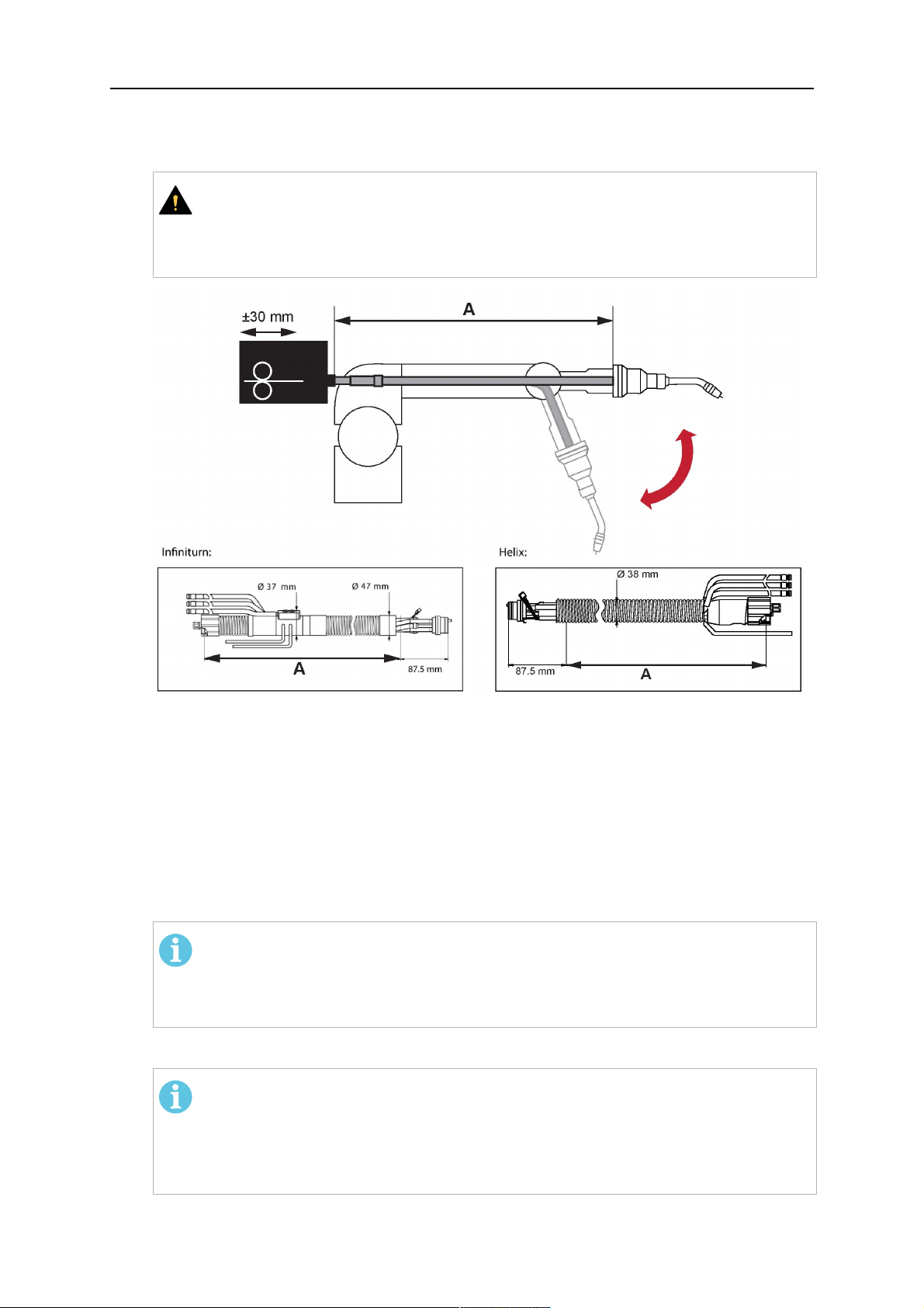
5.3.2 Mounting the cable assembly
NOTĂ!
In order to adjust the wire feeder position to the cable assembly length, it must be
mounted on an adjustable support with a possible movement of ±2-3cm (±1in.) to
the back and to the front. The length of the cable assembly must be determined
from the centred mounting position of the wire feeder.
1. Move the robot arm into a completely straight position, see illustration below. Make
sure that (1) axis 6 (rotation around the torch axis) is in 0° position.
2. Move the feeder (3) completely to the back in order to create space for inserting the
cable assembly. If it is not possible to move the feeder sufficiently, it should be
removed from the robot.
0463 373 101
- 33 -
© ESAB AB 2018

5 INSTALLATION
3. Insert the cable assembly with the coupling (2) first into the robot arm and feed it
through the robot wrist.
4. The feeder should only be installed again after the correct mounting position with
respect to the cable length has been determined. (See section "Installing the cable
assembly").
ATENȚIE!
Axis 6 must be in 0° position.
5.3.2.1 RTKSC-2 feeder cabinet connections
When installed for the first time, the position of the wire feeder cabinet must be adjusted to
the length of the cable assembly. First, the robot arm must be fully extended (straight).
ATENȚIE!
As long as the correct position of the feeder corresponding to the length of the cable
assembly has not been determined, be careful when moving the robot arm and
avoid overstretching the cable. It is helpful to loosen the positioning screws of the
feeder before moving the robot arm to allow the feeder to follow the cable assembly.
0463 373 101
- 34 -
© ESAB AB 2018
5 INSTALLATION
1. Loosen the sliding mechanism of the wire feeder and connect the cable assembly.
2. Now adjust the position of the wire feeder to suit the length of the Infiniturn or Helix
cable, as indicated with "A" in the illustration below.
ATENȚIE!
When adjusting the position of the feeder cabinet, make sure that the cable
assembly is not under stress when the robot arm is in stretched-out position.
It is normal for the cable assembly to sag slightly, it should never be taut.
3. Before securing the wire feeder in its permanent position, ensure that the Euro
connectors are tightly connected. Then turn the torch mount down and up again
(rotating on the axis 5), in order not to tighten the cable assembly too much against
the feeder (see illustration above). Once this is done, tighten the feeder in that
position.
4. For water cooled systems, connect the water lines to the cooling circuit. See section
"Cable assemblies for hollow wrist systems" in the TECHNICAL DATA chapter for
indications.
The hose with the blue rubber cap is for cooling water to the torch, the hose with the
red rubber cap returns the heated water. Make sure the hoses will not kink or get
otherwise blocked.
NOTĂ!
A Helix cable assembly used for a gas cooled system must not be connected
to a cooling circuit. As the water connections are not needed, they may be cut
off.
5. Connect the blow-out hose (black rubber cap) to the corresponding outlet of the wire
feeder.
NOTĂ!
If the blow-out function is not used, the blow-out hose must be sealed with the
rubber cap enclosed. With Infiniturn systems, the blow-out air must be
supplied to the corresponding connection hose, if it is not permitted to connect
blow-out air to the shield gas connection!
6. Install the necessary plug on the control cable and connect it to the safety off circuit
interface of the wire feeder (see section "Electrical connections").
0463 373 101
- 35 -
© ESAB AB 2018

5 INSTALLATION
5.3.3 RTKSC-2 cable assembly
The cable assembly must be aligned to the intended use in length and design. The type of
cooling for the torch and the cable assembly must be the same (either gas or water cooled
respectively). In order to prevent damage to the torch system and other components, it is
imperative to observe the following instructions.
ATENȚIE!
• Coordinate the length and design of the cable assembly to suit the range of
action of the robot.
• Do not bend, compress or overstretch the cable assembly.
• Fix the cable assembly such that is can be moved freely and cannot become
entangled.
• Any additional holding devices possibly installed, for example a balancer,
must not crush or bend the cable assembly.
• Extreme turning movements must be avoided in which the cable assembly
may become twisted.
• Chafing on the robot or other objects must be excluded.
5.3.3.1 RTKSC-2 cable assembly installation
NOTĂ!
For some robots, it may be possible to deviate from this order, and first connect the
cable assembly to the RTKSC-2, then thread the cable from the front through the
robot arm. If in doubt, follow the suggested order.
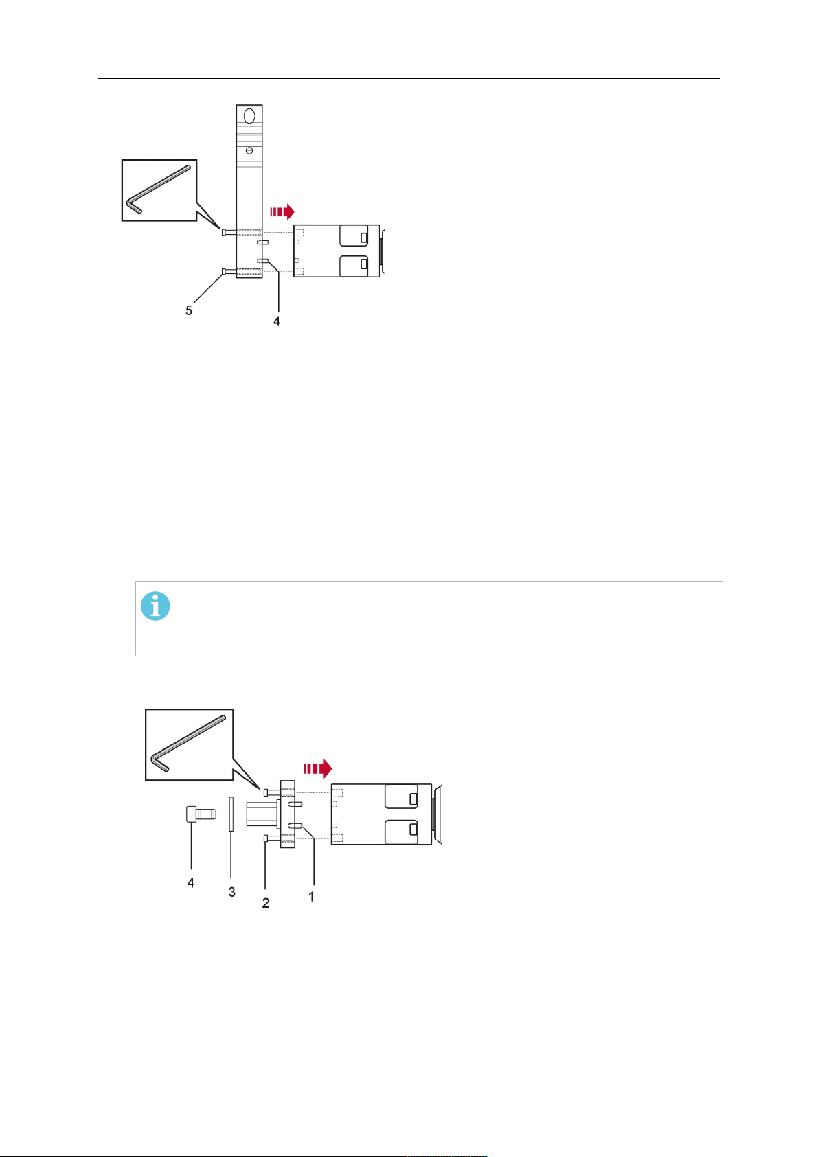
1. Loosen the three screws (7) with the associated washers and remove them from the
RTKSC-2 cover (1). See illustration below.
2. Install the supplied O-rings (4) into the grooves in the cover (1).
3. Pull the cable assembly approximately 15 cm (6 in.) from the main body (3).
0463 373 101
- 36 -
© ESAB AB 2018

5 INSTALLATION
4. Insert the coupling (2) into the socket of the cover (1) as shown. Align the index pin (6)
with the index hole (5) in the main body and insert completely.
NOTĂ!
Make sure that the position of the O-rings are not shifted by the index pin
during the assembly.
1 - RTKSC-2 cover 5 - Index hole
2 - Coupling 6 - Index pin
3 - RTKSC-2 main body 7 - 3× M5×35 screws
4 - 3× O-ring for water cooled systems 11 - Control cable connector
5. Insert the three screws (7) with the associated washers (8) and tighten gently with the
enclosed hexagonal wrench, see below illustration.
Fastening torque approximately 2 Nm (18 in.lb).
0463 373 101
- 37 -
© ESAB AB 2018

5 INSTALLATION
6. If present, insert the control cable plug (10) into the connector (11) and make sure it is
firmly seated.
7 - 3× M5×35 screw 11 - Control cable connector
8 - Washer 12 - 2× Micro switch
10 - Control cable plug 13 - Index pin
7. Gently push back the cable assembly into the robot arm and carefully seat the
RTKSC-2 cover (1) in place. Observe the index pin (13) to be in the correct position.
Make sure the two micro switches (12) are not damaged if present.
8. Insert the three M5 screws (14) and tighten without excessive force.
13. Index pin
14. 3× M5×12 screws
0463 373 101
- 38 -
© ESAB AB 2018

5 INSTALLATION
5.3.3.2 RTKSC-2 electrical connections
NOTĂ!
After connecting the control cable, secure the cable in order to protect it from getting
caught while the robot is moving.
Usually, the control cable will be directly connected to the wire feeder. See the
manufacturer's documentation for details. The link to the robot control is then
implemented via the power source controller.
RTKSC-2 safety-off mechanism connection
The switch for the safety-off functionality RTKSC-2 is connected through the control cable,
see (3) in the illustration below. This connects to the RTKSC-2 unit via the control cable plug
(1).
The safety-off signal requires a 2-wire connection (black/black) to the safety-off circuit in the
robot control (5).
If a collision is detected, the control circuit (normally closed) will be interrupted (4).
Rating of the control circuit: max. 48 V / 1 A.
1 - Control cable plug 3 - Burndy connector VVV
2 - EURO central connector
Pinii conectorului Burndy
A. Duză pentru gaz cu simț
tactil
C. Senzor de coliziune
F. 0V
G. + Tensiune motor
H. - Tensiune motor
D. Senzor de coliziune
E. Comandă prin închideri
succesive rapide
RTKSC-2 nozzle sense function connection
If the robot control provides a control circuit for nozzle sense functionality.
The connection is accomplished with a 2-wire connection (black/black) to the nozzle sense
circuit in the robot control (5), see illustration below.
0463 373 101
- 39 -
© ESAB AB 2018

5 INSTALLATION
Usually, the control cable will be directly connected to the wire feeder. See the
manufacturer's documentation for details. The link to the robot control is then implemented
via the power source robot interface.
Rating of the control circuit: max. 50 V / 5 A.
PERICOL!
If the nozzle sense function is not being used, the open end of the control cable on
the power source connection side must be properly isolated in order to avoid short
circuits. During certain problems on the torch head, the full welding potential may be
present on this cable.
ATENȚIE!
After detection of contact (gas nozzle on work piece), quickly reduce or cut off the
maximum current in the nozzle sense circuit in order to avoid overloading of the
system.
Allowed load max. 1 minute at the rated nominal current.
1 - Control cable plug 3 - Control cable
2 - EURO central connector
5.3.4 RTKSC-2 torch installation
Continue according to section "Torch installation".
0463 373 101
- 40 -
© ESAB AB 2018

5 INSTALLATION
5.4 RTFLC-2 installation
5.4.1 RTFLC-2 mount
1. Remove the three M5 screws (2) from the front cover (3) of the RT FLC-2 torch mount
and carefully pull the cover off the main body (4).
1 - Hexagon wrench 4 mm 3 - RT FLC-2 front cover
2 - 3× M5×12 screws 4 - RT FLC-2 main body
2. Now position the RT FLC-2 main body (4) on the adapter flange (6) so that the index
pin is correctly seated. Attach with the screws (5) enclosed
Fastening torque max. 2.2 Nm (19.5 in.lb).
1 - Hexagon wrench 4 mm 5 - 3× M5×12 hexagon socket screws
4 - RT FLC-2 main body 6 - Adapter flange
5.4.2 RTFLC-2 wire feeder connection
5.4.2.1 Feeding through the robot arm
NOTĂ!
In order to adjust the wire feeder position to the cable assembly length, it must be
mounted on an adjustable support with a possible movement of ± 2-3 cm (± 1 in.) to
the back and to the front. The length of the cable assembly must be determined
from the centred mounting position of the wire feeder.
0463 373 101
- 41 -
© ESAB AB 2018

5 INSTALLATION
1. Move the robot arm into a completely straight position, see illustration below. Make
sure that (1) axis 6 (rotation around the torch axis) is in 0° position.
2. Move the feeder (3) completely to the back in order to create space for inserting the
cable assembly. If it is not possible to move the feeder sufficiently, it should be
removed from the robot.
3. Insert the cable assembly with the coupling (2) first into the robot arm and feed it
through the robot wrist.
4. The feeder should only be installed again after the correct mounting position with
respect to the cable length has been determined. (See section "Installing the cable
assembly").
ATENȚIE!
Important! Axis 6 must be in 0° position.
5.4.2.2 RTFLC-2 feeder cabinet connections
When installed for the first time, the position of the wire feeder cabinet must be adjusted to
the length of the cable assembly. First, the robot arm must be fully extended (straight).
ATENȚIE!
As long as the correct position of the feeder corresponding to the length of the cable
assembly has not been determined, be careful when moving the robot arm and
avoid overstretching the cable. It is helpful to loosen the positioning screws of the
feeder before moving the robot arm to allow the feeder to follow the cable assembly.
0463 373 101
- 42 -
© ESAB AB 2018

5 INSTALLATION
1. Loosen the sliding mechanism of the wire feeder and connect the cable assembly.
Refer to the instruction of the feeder manufacturer.
2. Now adjust the position of the wire feeder to suit the length of the Infiniturn or Helix
cable, as indicated with "A" in the illustration below.
ATENȚIE!
When adjusting the position of the feeder cabinet, make sure that the cable
assembly is not under stress when the robot arm is in stretched-out position.
It is normal for the cable assembly to sag slightly, it should never be taut.
3. Before securing the wire feeder in its permanent position, ensure that the Euro
connections are tightly connected. Then turn the torch mount down and up again
(rotating on the axis 5), in order not to tighten the cable assembly too much against
the feeder (see illustration above). Once this is done, tighten the feeder in that
position.
4. For water cooled systems, connect the water lines to the cooling circuit. See section
"Cable assemblies for hollow wrist systems" in the TECHNICAL DATA chapter for
indications.
The hose with the blue rubber cap is for cooling water to the torch, the hose with the
red rubber cap returns the heated water. Make sure the hoses will not kink or get
otherwise blocked.
NOTĂ!
A Helix cable assembly used for a gas cooled system must not be connected
to a cooling circuit. As the water connections are not needed, they may be cut
off.
5. Connect the blow-out hose (black rubber cap) to the corresponding outlet of the wire
feeder.
NOTĂ!
If the blow-out function is not used, the blow-out hose must be sealed with the
rubber cap enclosed. With Infiniturn systems, the blow-out air must be
supplied to the corresponding connection hose, if it is not permitted to connect
blow-out air to the shield gas connection!
0463 373 101
- 43 -
© ESAB AB 2018

5 INSTALLATION
6. Install the necessary plug on the control cable and connect it to the safety off circuit
interface of the wire feeder (see section "Electrical connections").
5.4.3 RTFLC-2 cable assembly
The cable assembly must be aligned to the intended use in length and design. The type of
cooling for the torch and the cable assembly must be the same (either gas or water cooled
respectively). In order to prevent damage to the torch system and other components, it is
imperative to observe the following instructions.
ATENȚIE!
• Coordinate the length and design of the cable assembly to suit the range of
action of the robot.
• Do not bend, compress or overstretch the cable assembly.
• Fix the cable assembly such that is can be moved freely and cannot become
entangled.
• Any additional holding devices possibly installed, for example a balancer,
must not crush or bend the cable assembly.
• Extreme turning movements must be avoided in which the cable assembly
may become twisted.
• Chafing on the robot or other objects must be excluded.
5.4.3.1 RTFLC-2 cable assembly installation
In a hollow wrist system the recommended order of installation is to feed the cable assembly
through the robot arm before connecting the cables to the torch mount.
When the cable assembly is correctly installed in the hollow wrist, continue the installation
according to the procedure described below.
NOTĂ!
For some robots, it may be possible to deviate from this order, and first connect the
cable assembly to the RTKSC-2 and RTFLC-2, then thread the cable from the front
through the robot arm. If in doubt, follow the suggested order.
1. Loosen the three screws (7) with the associated washers and remove them from the
RTFLC-2 cover (1). See illustration below.
2. Install the supplied O-rings (4) into the grooves in the cover (1). For gas cooled
systems, only one O-ring (4a) is needed, for water cooled systems all three O-rings
are needed.
3. Pull the cable assembly approximately 15 cm (6 in.) from the main body (3).
0463 373 101
- 44 -
© ESAB AB 2018

5 INSTALLATION
4. Insert the coupling (2) into the socket of the cover (1) as shown. Align the index pin (6)
with the index hole (5) in the main body and insert completely.
NOTĂ!
Take great care that the position of the O-rings is not shifted by the index pin
during the assembly.
1 - RT FLC-2 cover 5 - Index hole
2 - Coupling 6 - Index pin
3 - RT FLC-2 main body 7 - 3× M5×35 screws
4 - 3× O-ring for water cooled systems 11 - Control cable connector
5. Insert the three screws (7) with the associated washers (8) and tighten gently with the
enclosed hexagonal wrench, see below illustration.
Fastening torque approximately 2 Nm (18 in.lb).
0463 373 101
- 45 -
© ESAB AB 2018

5 INSTALLATION
6. If present insert the control cable plug (10) into the connector (11) and make sure it is
firmly seated.
7 - 3× M5×35 screw 11 - Control cable connector
8 - Washer 12 - 2× Micro switch
10 - Control cable plug 13 - Index pin
7. Gently push back the cable assembly into the robot arm and carefully seat the
RTFLC-2 cover (1) in place. Observe the index pin (13) to be in the correct position.
Make sure the two micro switches (12) are not damaged if present.
8. Insert the three M5 screws (14) and tighten without excessive force.
13 - Index pin 14 - 3x M5x12 screws
0463 373 101
- 46 -
© ESAB AB 2018

5 INSTALLATION
5.4.4 RTFLC-2 electrical connections
NOTĂ!
After connecting the control cable, secure the cable in order to protect it from getting
caught while the robot is moving.
Usually, the control cable will be directly connected to the wire feeder. See the
documentation of the manufacturer for details. The link to the robot control is then
implemented via the power source controller.
5.4.4.1 RTFLC-2 hollow wrist system with Infiniturn cable assembly
Connecting the nozzle sense function
If the robot control provides a control circuit for nozzle sense functionality.
The connection is accomplished with a 2-wire connection (black/black) to the nozzle sense
circuit in the robot control (5), see illustration below.
Usually, the control cable will be directly connected to the wire feeder. See the
manufacturer's documentation for details. The link to the robot control is then implemented
via the power source robot interface.
Rating of the control circuit: max. 50 V / 5 A.
PERICOL!
If the nozzle sense function is not being used, the open end of the control cable on
the power source connection side must be properly isolated in order to avoid short
circuits. During certain problems on the torch head, the full welding potential may be
present on this cable.
ATENȚIE!
After detection of contact (gas nozzle on work piece), quickly reduce or cut off the
maximum current in the nozzle sense circuit in order to avoid overloading of the
system.
Allowed load max. 1 minute at the rated nominal current.
1 - Control cable plug 3 - Control cable
2 - EURO central connector
0463 373 101
- 47 -
© ESAB AB 2018

5 INSTALLATION
5.4.4.2 RTFLC-2 hollow wrist system with Helix cable assembly
Connecting the nozzle sense function
If the robot control provides a control circuit for nozzle sense functionality.
The connection is accomplished with a 1-wire connection (green) to the nozzle sense circuit
in the robot control (5), see illustration below.
Usually, the control cable will be directly connected to the wire feeder. See the
manufacturer's documentation for details. The link to the robot control is then implemented
via the power source robot interface.
Rating of the control circuit: max. 50 V / 5 A.
PERICOL!
If the nozzle sense function is not being used, the open end of the control cable on
the power source connection side must be properly isolated in order to avoid short
circuits. During certain problems on the torch head, the full welding potential may be
present on this cable.
ATENȚIE!
After detection of contact (gas nozzle on work piece), quickly reduce or cut off the
maximum current in the nozzle sense circuit in order to avoid overloading of the
system.
Allowed load max. 1 minute at the rated nominal current.
1 - Control cable plug 3 - EURO central connector
2 - Control cable 4 - Burndy connector
5.5 Torch installation
Be sure to use the correct version of the torch mount and cable assembly (water or gas
cooled).
5.5.1 Torch neck equipment
The torch neck, see (1) in the illustration below, must always be equipped to suit the wire
diameter and material.
0463 373 101
- 48 -
© ESAB AB 2018

5 INSTALLATION
1. Select the correct wire guide, contact tip (4), tip holder (2), gas nozzle (5), and gas
diffuser/spatter protection (3). You will find an exact overview and possible alternative
equipment elements for various torch models in the spare parts list. Only use original
ESAB parts; only then is the fitting accuracy ensured.
2. Firmly tighten the tip holder and the contact tip using a suitable tool for example the
enclosed monkey wrench.
3. When using a split wire guide, remove the installed guide nipple including the o-ring
from the torch flange upon delivery if necessary (see section "Installing the neck
liner").
ATENȚIE!
The torch must be completely equipped before welding, especially the gas
diffuser and/or spatter protection and all necessary insulators have to be
installed according to the spare parts list. Welding without these items may
cause immediate destruction of the torch.
1 - Torch neck 4 - Contact tip
2 - Tip holder 5 - Contact tip
3 - Gas diffuser
5.5.2 Aristo RT torch neck installation
NOTĂ!
Check the O-rings on the flange of the torch neck before mounting. Replace the
O-rings if damaged or lost. Missing or faulty O-rings will lead to leaks of shielding
gas and coolant.
1. For hollow wrist systems, insert the torch into the torch mount in the correct
orientation, so that the locator pin fits into the slot of the RTKSC-2 or RTFLC-2
interface, see (A) in the illustration below. For standard systems, attach the torch to
the RT flange of the cable assembly, (B) in the illustration below.
Installation is only possible in the correct orientation.
2. Tighten the locking nut of the torch neck.
NOTĂ!
Only tighten by hand, never use tools or excessive force.
0463 373 101
- 49 -
© ESAB AB 2018

5 INSTALLATION
3. The correct seating of the torch can be checked by means of the window (1). If the
torch has been correctly mounted, no gap should be seen through the window (1).
5.6 Installing the wire guide for standard and hollow Wrist arm
Installing the wire guide
Choose the wire guide or liner depending on the filler wire material and diameter to be used,
see the spare parts list. Accurate performance of the system can only be guaranteed when
using original ESAB wire guides.
The recommended wire guide is the split wire guide, which consists of the neck liner and a
separate guide in the cable assembly. The front part of the wire guide, which is most
stressed, can be exchanged easily and independently of the cable assembly wire guide.
For correct installation, the following steps must be followed (example for Euro central
connector).
5.6.1 Installing the neck liner
The neck liner must be selected to fit the material and diameter of the welding wire, see the
spare parts list.
0463 373 101
- 50 -
© ESAB AB 2018

5 INSTALLATION
1. If present, remove the central guide nipple (1), from the torch neck using a hexagon
wrench (size 6 mm) or a large flat-blade screwdriver.
NOTĂ!
The guide nipple (1) can only be used with one-piece liners and must not be
used with the standard RT or hollow wrist system.
2. When replacing the neck liner:
Unfasten the sleeve nut and remove the torch neck.
Unfasten the liner nipple using a hexagon wrench (size 6 mm) and remove nipple and
liner from the torch neck.
3. Remove the gas nozzle and the contact tip.
4. Insert the new neck liner (2) into the torch. Carefully tighten the guide nipple using a
suitable tool, e.g. a hex-wrench (size 6 mm) or a large flat-blade screwdriver.
5. Cut the neck liner flush with the tip holder and remove the neck liner from the torch.
6. Install the contact tip.
7. Insert the neck liner again. It will be stopped by the contact tip. Measure the excess
liner sticking out of the neck.
8. Remove the liner again and shorten the front end by the measured length. Carefully
deburr the edge and make sure that the inner hole is not blocked.
9. Reinstall the neck liner and tighten the guide nipple in the neck.
5.6.2 Installing a split wire guide in the cable assembly
The correct liner must be inserted to suit the filler material and the wire diameter, see the
spare parts list.
The wire guide is inserted through the cable assembly from the rear, reaching the guide
nipple that is installed in the flange where the torch neck will be attached. The following
worksteps must be followed in order to correctly determine the wire guide length. (Example
for Euro central connector).
0463 373 101
- 51 -
© ESAB AB 2018

5 INSTALLATION
1. For standard RT system: Install the guide nipple (1) in the center hole of the neck
support flange, see illustration A below.
For hollow wrist system: Install the guide nipple (1) into the torch interface of the
RTKSC-2 / RTFLC-2 cover, see illustration B below.
2. Remove the sleeve nut (2) from the central connector, and remove the old wire guide.
3. Insert the wire guide through the central connection and push forwards as far as it will
go into the guide nipple (1), applying light pressure.
ATENȚIE!
Ensure that the wire guide has advanced right up to the stop at the front,
rotating and pushing forward gently.
4. Measure the excess length that needs to be cut from the wire guide.
5. Remove the wire guide again and shorten the front end by the measured length.
Steel liner: grind down the burred edges if needed.
Plastic liner: make a clean cut and chamfer the edges (e.g. with a pencil sharpener)
NOTĂ!
Make sure the inner opening of the liner is not obstructed by the cut wire end.
0463 373 101
- 52 -
© ESAB AB 2018

5 INSTALLATION
6. Reinstall the wire guide and attach the sleeve nut (2).
NOTĂ!
For hollow wrist systems where Infiniturn and Helix cable assemblies are
used, wire guides should be installed without tension so that the ends of the
liners may rotate freely.
Important note when using a plastic liner:
The wire channel between the drive rolls of the feeder and the central
connector of the torch must be fitted with a plastic liner. Depending on the
design of the feeder, a piece of plastic liner inserted into a brass guide tube
can be used.
During wire run-in, make sure that the wire is fed correctly into the plastic liner
of the torch. If necessary, remove the cable assembly from the feeder and
insert the wire, then reattach.
5.6.3 Installing a continuous wire guide in the cable assembly
Installing a steel liner
The wire guide is inserted through the cable assembly from the rear and reaches to the
contact tip. The following worksteps must be followed for the correct calculation of the length
(example for Euro central connector):
1. Install the torch (see section "Torch neck equipment").
2. Remove the gas nozzle and contact tip from the torch.
3. Remove the sleeve nut (D) from the Euro connector.
4. Push in the liner through the central connector and fix with the sleeve nut.
5. Cut off the liner flush with the nozzle holder. To determine the thread projection of the
contact tip, pull the liner backwards and screw in the contact tip.
6. Push the liner forwards as far as it will go to the contact tip applying light pressure on
the liner and measure the length to be shortened at the rear.
7. Now remove the liner again and cut the excess length measured off it’s front end. If
needed, grind down the burred edges. Make sure the inner opening of the liner is not
obstructed by the cut wire end.
8. The insulation of the liner must be removed after cutting off in the front area, such that
the insulation protrudes out of the RM2 flange by approx. 5 cm. For this, briefly
remove the torch neck.
9. Push the liner back in again and fix with the sleeve nut (D), see above. Re-install the
gas nozzle.
0463 373 101
- 53 -
© ESAB AB 2018

5 INSTALLATION
Installing a plastic liner
1. Mount the torch neck (see section "Torch neck equipment") and equip it with a gas
nozzle and contact tip.
2. Remove the sleeve nut (D) from the Euro connector.
3. Cleanly cut off the liner, slightly break the outer edges, point slightly (e.g. with a pencil
sharpener).
4. Insert the liner through the central connector into the cable assembly with fitted torch.
If it gets stuck, rotate the liner to free it and facilitate installation.
NOTĂ!
Make sure the liner is completely inserted by rotating it and slightly pushing it
forward, until you can feel it has reached its stop.
5. Mount the nipple (B) and the O-Ring (C), move it to the right position and fix it with the
sleeve nut (D) of the Euro central connector.
6. Measure the required overlap needed inside the wire feeder cabinet and cut the liner
accordingly.
5.7 Adjust the narrow gap contact tip
The adjusting tool RT42-NG is designed for the narrow gap torch necks RT42W-NG,
RT42G-NG and RT 82W-0°NG, torches with curved narrow gap contact tip. It facilitates the
precisely repeatable and fast changing of the curved contact tip.
NOTĂ!
The adjusting tool must be securely fastened to a stable base, in order to prevent
the position of the device in relation to the robot cannot change unintentionally. If the
exact orientation of the device is lost, the alignment of the contact tip used for the
elaboration of the welding programs can no longer be reproduced with precision.
Select a position within the operating range of the robot for orientation (alignment) of the
contact tip to the torch. Fasten the adjusting tool firmly to a base using the fastening grooves
provided for this purpose. Fastening material is not included with the adjusting tool. Select
fastening material (screws) to suit the existing conditions.
Save all motion sequences and stop positions required to change or align the wearing parts
to a separate robot program.
Before programming the welding tasks: plan at which orientation the contact tip is to stand in
relation to the torch. The torch must then be positioned in the desired rotational position and
the contact tip aligned using the adjusting device. Only then may the welding task be
programmed. If different orientations of the contact tip are required for various welding tasks,
the contact tip has to be aligned to the new position when the welding task is changed.
AVERTIZARE!
The gas nozzle and the torch head become very hot during welding. Always allow
the torch to cool down before replacing wearing parts or adjusting the contact tip.
0463 373 101
- 54 -
© ESAB AB 2018

5 INSTALLATION
Adjust the contact tip
Move the robot torch to a position parallel to
the opening of the adjusting tool (2). Maintain
a sufficient distance to the work table to be
able to comfortably remove the gas nozzle.
Define this position in your robot program as
the wearing parts change position (stop
position 1).
Remove the gas nozzle by pulling it
downwards. Remove the welding wire in the
contact tip if necessary.
Loosen the counter nut (4) of the contact tip
while counter-holding the nozzle holder at the
wrench flat (3).
Unscrew the contact tip including the counter
nut from the nozzle holder and replace the
nozzle holder if necessary.
Completely screw the counter nut (4) onto the
new contact tip. Screw the contact tip
including the counter nut into the nozzle
holder.
Align the contact tip until it is parallel to the
opening of the adjusting tool. If necessary,
slightly unscrew the contact tip so that it can
be easily turned in both directions.
0463 373 101
- 55 -
© ESAB AB 2018

5 INSTALLATION
NOTĂ!
The contact tip must be able to be
easily moved by hand in both
directions in order to enable the
threading of the adjusting tool.
Place the robot torch or contact tip directly in
front of the opening of the adjusting tool (2)
(stop position 2).
Insert it slowly from the front until it is
completely inserted into the device (stop
position 3).
The contact tip was aligned exactly in the
device during insertion. Now cautiously
tighten the counter nut (4) in this position,
while counter holding the nozzle holder at the
wrench flat.
Slowly move the robot torch out of the
adjusting gauge, return to stop position 1 and
push on the gas nozzle as far as it will go.
Allow the welding wire to run into the contact
tip and bring the robot arm into welding
position.
0463 373 101
- 56 -
© ESAB AB 2018

6 OPERATION
6 OPERATION
ATENȚIE!
Before starting the system, check the whole installation according to the
manufacturer's instructions and applicable safety regulations.
Check the following to make sure that the system has been installed correctly:
1. Are all parts securely attached (torch, torch mount, flanges, safety-off device, cable
assembly, and wire feeder cabinet)?
2. Are all media hoses connected correctly and protected from damage?
3. Is the EURO central connector or direct connector fastened tightly?
4. Is the cable assembly length correct and suitable for the installation and can the cable
rotate freely? The cable must not be bent sharply. Any risk of the cable getting caught
on another object must be eliminated.
5. Is the control cable of the safety-off circuit connected and functioning? Move torch by
hand to test (RTKSC-2 and RTKS-2 only).
6. Is the torch firmly attached and is it completely equipped?
7. Is the wire guide installed according to the manual?
8. Are all lines and tubes arranged so that they cannot be damaged or bent?
The wire run-in can now be started, either via the wire run-in pushbutton or via the wire run-in
at the feeder.
6.1 Important information for programming (hollow wrist system only)
Fast rotation of axis 6 of the robot will significantly stress the cable assembly. In certain
cases, this can lead to damage or destruction of the cable. In order to maximize the lifetime
of the cable, we strongly suggest respecting the following limitations when programming the
robot.
Position of axis 5 Max. rotational speed of axis 6
0 – 60° 100 % (no limitations)
60° – 80° 300°/sec (approximately 50 % of max. robot speed)
> 80° 120°/sec (approximately 20 % of max. robot speed)
NOTĂ!
The above values are only indications. For information on the exact rotational speed
limits, refer to the individual robot manual or contact the robot supplier.
To reposition the torch quickly, the robot arm may have to be slightly extended first to achieve
a bending angle of max. 60° of axis 5. In this position, the maximum available rotation speed
of axis 6 can be used.
When using the ESAB Helix cable assembly, the max. rotation of ±270° from the neutral
position must not be exceeded.
0463 373 101
- 57 -
© ESAB AB 2018

6 OPERATION
ATENȚIE!
While axis 5 is bent more than 60°, the rotational speed of the torch around axis 6
must be limited, see table above.
Otherwise, the cable assembly may be damaged.
0463 373 101
- 58 -
© ESAB AB 2018

7 SERVICE ŞI ÎNTREŢINERE
7 SERVICE ŞI ÎNTREŢINERE
AVERTIZARE!
Înainte de a efectua întreținerea sistemului, opriți rețeaua principală de alimentare a
instalației. Rețineți reglementările privind siguranța de la începutul acestui manual.
Nu utilizați arzătoare sau ansambluri de cabluri deteriorate! Defectele cunoscute
trebuie să fie reparate de către un personal calificat înainte de a reutiliza
echipamentul.
AVERTIZARE!
Risc de vătămare prin ardere! Duza pentru gaz și capul arzătorului se
supraîncălzesc în timpul sudurii. Lăsați arzătorul să se răcească înainte de a
efectua lucrările de întreținere.
AVERTIZARE!
Pentru a preveni vătămările personale sau deteriorarea instalației, respectați
următoarele instrucțiuni:
1. Repararea montajului arzătorului RTKSC-2 sau RTFLC-2, a mecanismului
safety-off RTKS-2, a ansamblului de cabluri sau a cuplajul mediului
Infiniturn trebuie efectuată numai de către serviciile de asistență ESAB.
2. Nu deschideți niciodată cuplajul mediului Infiniturn. Acesta nu conține piese
care pot fi reparate de către utilizator și va fi distrus prin dezasamblare.
3. Nu dezasamblați niciodată RTKSC-2 sau RTKS-2. Acesta este un
mecanism acționat cu arc. Manipularea incorectă poate duce la vătămări
grave.
7.1 Verificări și măsuri obligatorii
Înainte de fiecare utilizare:
• Verificați arzătorul, vârful de contact, duza pentru gaz, manșonul gâtului, cablurile și
echipamentul general pentru deteriorări generale.
NOTĂ!
Pentru a minimiza timpii de staționare, se recomandă să alternați între două gâturi
de arzătoare, având întotdeauna la îndemână un gât de arzător proaspăt echipat și
pregătit de utilizare.
La fiecare 8 ore de utilizare (în funcție de aplicație):
• Schimbaţi vârful de contact.
Zilnic:
• Efectuați o verificare funcțională manuală a mecanismului safety-off.
• Efectuați o inspecție vizuală pentru deteriorări - de ex., încovoieri sau fisuri.
• Verificați poziția corectă a alimentatorului de sârmă. Ansamblul de cabluri nu trebuie să
fie prea tensionat sau încovoiat.
• Inspectați conexiunile mediilor și cuplajul mediului Infiniturn pentru scurgeri.
• Curățați și întrețineți arzătorul conform manualului arzătorului.
La fiecare 40 ore de utilizare (în funcție de aplicație):
0463 373 101
- 59 -
© ESAB AB 2018

7 SERVICE ŞI ÎNTREŢINERE
• Schimbați manşoanele pentru sârmă.
• Schimbați manşoanele pentru gât.
Săptămânal sau la nevoie, în funcție de utilizare:
• Scoateți ghidajul pentru sârmă și verificați uzura și depunerile de murdărie. Înlocuiţi-l,
dacă este necesar.
Lunar sau mai frecvent, în condiții de utilizare intensă (adică peste 8 ore/zi):
• Suflați canalul de ghidare a sârmei cu aer comprimat (scoateți vârful de contact și
ghidajul pentru sârmă).
• Asiguraţi-vă că toate șuruburile sunt strânse.
• Inspectați toate racordurile și furtunurile pentru deteriorări.
• Înlocuiți după 250 kg de sârmă sudată.
Deteriorarea izolației electrice trebuie reparată de către un personal instruit înainte ca
sistemul să poată fi utilizat în siguranță.
0463 373 101
- 60 -
© ESAB AB 2018

8 DEPANARE
8 DEPANARE
Defecţiune Cauză posibilă Măsură
Nu se poate
alimenta cu
sârmă
Sârma de sudură nu a fost
îndreptată înainte de a fi introdusă
în ansamblul de cabluri
Arzătorul și ansamblul de cabluri nu
sunt echipate corect pentru
diametrul sârmei și materialul
sârmei
Ghidajul pentru sârmă nu este
introdus corect în ansamblul de
cabluri
Vârful de contact blocat este blocat
cu resturi de sârmă
Ghidajul pentru sârmă este uzat
Alimentatorul de sârmă este reținut
de murdărie și resturile din arzător
Dacă este nevoie, scoateți sârma
de sudură din nou, tăiați și
debavurați capătul și îndreptați
primii 10 cm de sârmă. Apoi,
înfiletați înapoi în ansamblul de
cabluri.
Verificați ghidajul pentru sârmă
(ansamblul de cabluri și gâtul
arzătorului) și vârful de contact.
Scoateți puțin de ghidajul pentru
sârmă din conectorul Euro. Atunci
când introduceți ghidajul pentru
sârmă, trebuie să simțiți cum ultimii
centimetri se glisează în niplul
ghidajului din interfața arzătorului. În
caz contrar, ghidajul pentru sârmă
poate fi prea scurt și să nu fie
introdus complet.
Înlocuiți vârful de contact și/sau
ghidajul de sârmă, suflați gâtul
arzătorului, conducta ghidajului
pentru sârmă și ghidajul pentru
sârmă cu aer comprimat.
Arzătorul devine
prea fierbinte
Vârful de contact sau suportul
vârfului nu este strâns corect
Sistemul de răcire nu funcţionează
corect
Sistemul de răcire nu este racordat
corect
Utilizați o unealtă adecvată pentru a
strânge manual.
Verificaţi debitul apei, nivelul de
umplere şi gradul de curăţenie.
Verificați racordurile (admisie și
retur apă).
Arzător suprasolicitat Respectaţi datele tehnice, dacă
este necesar, alegeţi un tip diferit.
Ansamblu cabluri defect Verificaţi cablurile, tuburile şi
conexiunile.
0463 373 101
- 61 -
© ESAB AB 2018

8 DEPANARE
Defecţiune Cauză posibilă Măsură
Probleme
referitoare la
avansul sârmei
Alimentatorul
de sârmă se
oprește în
timpul sudurii
Vârful de contact este uzat Înlocuiţi vârful de contact.
Manşonul este uzat / murdar Verificați manșonul; suflați.
Înlocuiţi-l, dacă este necesar.
Consumabilele utilizate nu sunt
Verificaţi lista pieselor de schimb.
adecvate pentru diametrul sau
materialul sârmei
Alimentatorul de sârmă nu este
configurat corect
Verificaţi cilindrii de alimentare cu
sârmă, presiunea de contact şi
frâna bobinei.
Ansamblul de cabluri este îndoit sau
configurat cu raze prea mici
Verificaţi ansamblul de cabluri
pentru deteriorări. Puteți introduce
manșonul cu ușurință? Instalați
conform instrucțiunilor. Consultați
secţiunea „Montarea ansamblului
de cabluri”.
Sârma este contaminată Utilizaţi o lavetă de curăţare.
Bobina de sârmă este goală Verificați cantitatea de sârmă de
sudură de pe bobina din
alimentatorul de sârmă.
Blocajul sârmei în ansamblul de
cabluri
Verificați alimentarea cu sârmă
(posibil prea rapidă), verificați vârful
de contact pentru
contaminare/înfundare, curățați sau
înlocuiți vârful de contact, dacă este
nevoie.
Procesul de
sudură se
oprește
Pori prezenți în
îmbinare
Arcul nu este
stabil
Sârmă stinsă în vârful de contact
Înlocuiţi vârful de contact.
sau vârf de contact uzat
S-a declanșat mecanismul
safety-off.
Căutați punctele de coliziune și
preveniți-le. Verificați conducta de
comandă pentru un contact slăbit.
Vortex de gaz cauzat de aderenţa
stropilor
Curăţaţi capul arzătorului, utilizaţi
un difuzor de gaz/protecţie la
împroşcare.
Flux de gaz prea mic sau extrem de
ridicat în arzător
Verificaţi debitul folosind
instrumentul de măsurare.
Alimentare cu gaz defectă Verificaţi debitul şi scurgerile
posibile.
Umezeală sau contaminare a
sârmei sau a piesei de prelucrat
Verificaţi sârma şi piesa de
prelucrat, utilizaţi mai puţin lichid
anti-împroşcare sau unul diferit.
Vârful de contact este uzat Înlocuiţi vârful de contact.
Parametri de sudură incorecţi Verificați configurarea
echipamentului de sudură.
Conexiuni electrice insuficiente în
circuit
Verificați toate conexiunile electrice
(inclusiv cablul de împământare)
dintre sursa de alimentare a
arzătorului sau piesa de prelucrat
pentru o fixare fermă.
0463 373 101
- 62 -
© ESAB AB 2018

9 COMANDAREA PIESELOR DE SCHIMB
9 COMANDAREA PIESELOR DE SCHIMB
ATENȚIE!
Reparațiile și lucrările electrice trebuie efectuate de un tehnician de service autorizat
de ESAB. Utilizați numai piese de schimb și de uzură originale marca ESAB.
Arzătoarele ESAB RT, RTKS-2, RTFL-2, RT-KSC-2, RT-FLC-2, RT42, RT52, RT62,
RT72, RT82, RT42-NG și RT82WNG sunt proiectate și testate conform standardelor
europene și internaționale IEC/EN 60974-7. Unitatea de service care a efectuat lucrările de
service sau de reparaţii are obligaţia de a se asigura că produsul se conformează în
continuare cu standardul menţionat.
Piesele de schimb şi consumabilele se pot comanda prin intermediul celui mai apropiat
dealer ESAB; vizitaţi esab.com. Atunci când comandați, vă rugăm să specificați tipul de
produs, numărul de serie, denumirea și codul piesei de schimb în conformitate cu lista de
piese de schimb. Astfel se simplifică expedierea și se asigură livrarea corectă.
0463 373 101
- 63 -
© ESAB AB 2018

ESAB AB, Lindholmsallén 9, Box 8004, 402 77 Gothenburg, Sweden, Phone +46 (0) 31 50 90 00
http://manuals.esab.com
For contact information visit esab.com
 Loading...