


RT Robo Welding Torch System
RTKS-2, RTFL-2, KSC-2, FLC-2, RT42, RT52,
RT62, RT72, RT82, RT42-NG, RT82WNG
Οδηγίες χρήσεως
0463 373 101 GR 20181227


ΠΊΝΑΚΑΣ ΠΕΡΙΕΧΟΜΈΝΩΝ
1
ΑΣΦΑΛΕΙΑ................................................................................................... 5
1.1 Σημασία συμβόλων ................................................................................ 5
1.2 Προφυλάξεις ασφαλείας ........................................................................ 5
2
ΕΓΓΥΗΣΗ ..................................................................................................... 9
2.1 Προϋποθέσεις προβλεπόμενης χρήσης .............................................. 9
3
ΕΙΣΑΓΩΓΗ.................................................................................................... 11
3.1 Επισκόπηση συστημάτων με τσιμπίδα συγκόλλησης ...................... 12
4
ΤΕΧΝΙΚΑ ΣΤΟΙΧΕΙΑ .................................................................................... 14
4.1 Λαιμός τσιμπίδας συγκόλλησης ........................................................... 14
4.2 Ονομαστική τάση ................................................................................... 15
4.2.1 Όρια κυκλώματος ψύξης ...................................................................... 16
4.3 Βάση τσιμπίδας...................................................................................... 16
4.3.1 Βάσεις τσιμπίδας για τυπικό σύστημα RT ............................................ 16
4.3.1.1 Μηχανισμός διακοπής ασφαλείας RTKS-2....................................... 17
4.3.1.2 Ενδιάμεση φλάντζα RTFL-2 ............................................................. 17
4.3.2 Βάσεις τσιμπίδας για σύστημα με κοίλο καρπό.................................... 18
4.3.2.1 Βάση τσιμπίδας RTKSC-2 G/W με μηχανισμό διακοπής ασφαλείας 19
4.3.2.2 Άκαμπτη βάση σύνδεσης RTFLC-2 G/W ......................................... 20
4.4 Φλάντζες προσαρμογής ........................................................................ 21
4.5 Διατάξεις καλωδίων ............................................................................... 21
4.5.1 Διατάξεις καλωδίων για τυπικό σύστημα RT ........................................ 21
4.5.2 Διατάξεις καλωδίων για συστήματα με κοίλο καρπό ............................ 22
5
INSTALLATION............................................................................................ 24
5.1 RTKS-2 standard arm installation........................................................ 24
5.1.1 RTKS-2 safety-off mechanism............................................................. 24
5.1.1.1 Torch installation with adjustable mount............................................ 25
5.1.2 Standard arm cable assembly for KS-2 and FL-2 ................................ 27
5.1.3 RTKS-2 wire feeder connection........................................................... 28
5.1.4 RTKS-2 electrical connections ............................................................ 29
5.1.4.1 RTKS-2 safety-off mechanism connection ....................................... 29
5.1.5 RTKS-2 Torch installation .................................................................... 30
5.2 RTFL-2 standard arm installation ........................................................ 31
5.2.1 RTFL-2 rigid mount.............................................................................. 31
5.2.2 RTFL-2 torch installation ..................................................................... 33
5.3 RTKSC-2 hollow wrist system installation.......................................... 33
5.3.1 RTKSC-2 mount with safety off mechanism........................................ 33
5.3.2 Mounting the cable assembly............................................................... 34
5.3.2.1 RTKSC-2 feeder cabinet connections .............................................. 35
5.3.3 RTKSC-2 cable assembly ................................................................... 37
5.3.3.1 RTKSC-2 cable assembly installation .............................................. 37
5.3.3.2 RTKSC-2 electrical connections....................................................... 40
0463 373 101 © ESAB AB 2018

ΠΊΝΑΚΑΣ ΠΕΡΙΕΧΟΜΈΝΩΝ
5.3.4 RTKSC-2 torch installation .................................................................. 41
5.4 RTFLC-2 installation.............................................................................. 42
5.4.1 RTFLC-2 mount................................................................................... 42
5.4.2 RTFLC-2 wire feeder connection......................................................... 42
5.4.2.1 Feeding through the robot arm .......................................................... 42
5.4.2.2 RTFLC-2 feeder cabinet connections ............................................... 43
5.4.3 RTFLC-2 cable assembly .................................................................... 45
5.4.3.1 RTFLC-2 cable assembly installation ............................................... 45
5.4.4 RTFLC-2 electrical connections .......................................................... 48
5.4.4.1 RTFLC-2 hollow wrist system with Infiniturn cable assembly........... 48
5.4.4.2 RTFLC-2 hollow wrist system with Helix cable assembly................. 49
5.5 Torch installation .................................................................................... 49
5.5.1 Torch neck equipment .......................................................................... 49
5.5.2 Aristo RT torch neck installation ........................................................... 50
5.6 Installing the wire guide for standard and hollow Wrist arm ............. 51
5.6.1 Installing the neck liner......................................................................... 51
5.6.2 Installing a split wire guide in the cable assembly ................................ 52
5.6.3 Installing a continuous wire guide in the cable assembly ..................... 54
5.7 Adjust the narrow gap contact tip ........................................................ 55
6
OPERATION ................................................................................................ 58
6.1 Important information for programming (hollow wrist system only) 58
7
ΣΕΡΒΙΣ ΚΑΙ ΣΥΝΤΗΡΗΣΗ ........................................................................... 60
7.1 Υποχρεωτικοί έλεγχοι και ενέργειες..................................................... 60
8
ΑΝΤΙΜΕΤΩΠΙΣΗ ΠΡΟΒΛΗΜΑΤΩΝ............................................................. 62
9
ΠΑΡΑΓΓΕΛΙΑ ΑΝΤΑΛΛΑΚΤΙΚΩΝ .............................................................. 65
Με την επιφύλαξη του δικαιώματος τροποποίησης των τεχνικών προδιαγραφών χωρίς προηγούμενη ειδοποίηση.
0463 373 101 © ESAB AB 2018

1 ΑΣΦΑΛΕΙΑ
1 ΑΣΦΑΛΕΙΑ
1.1 Σημασία συμβόλων
Όπως χρησιμοποιούνται σε αυτό το εγχειρίδιο: Σημαίνει "Προσοχή!" Να είστε σε
εγρήγορση!
ΚΙΝΔΥΝΟΣ!
Υποδεικνύει ότι υπάρχουν άμεσοι κίνδυνοι που, αν δεν αποφευχθούν, θα
οδηγήσουν σε άμεσο, σοβαρό τραυματισμό ή θάνατο.
ΠΡΟΕΙΔΟΠΟΙΗΣΗ!
Υποδεικνύει ότι υπάρχουν πιθανοί κίνδυνοι που μπορεί να οδηγήσουν σε
τραυματισμό ή θάνατο.
ΠΡΟΣΟΧΗ!
Υποδεικνύει ότι υπάρχουν κίνδυνοι που μπορεί να οδηγήσουν σε ελαφρύ
τραυματισμό.
ΠΡΟΕΙΔΟΠΟΙΗΣΗ!
Πριν από τη χρήση, διαβάστε και κατανοήστε το
εγχειρίδιο οδηγιών και τηρήστε όλες τις ετικέτες, τις
πρακτικές ασφαλείας του εργοδότη και τα δελτία
δεδομένων ασφαλείας (SDS).
1.2 Προφυλάξεις ασφαλείας
Οι χρήστες του εξοπλισμού ESAB έχουν την τελική ευθύνη να εξασφαλίζουν ότι
οποιοσδήποτε εργάζεται στον εξοπλισμό ή κοντά σε αυτόν τηρεί όλες τις σχετικές
προφυλάξεις ασφαλείας. Οι προφυλάξεις ασφαλείας πρέπει να ικανοποιούν τις απαιτήσεις
που ισχύουν για εξοπλισμό αυτού του τύπου. Επιπλέον των τυπικών κανονισμών που
εφαρμόζονται στον τόπο εργασίας, θα πρέπει να τηρούνται οι ακόλουθες συστάσεις.
Όλες οι εργασίες πρέπει να διεξάγονται από εκπαιδευμένο προσωπικό που έχει πλήρη
γνώση της λειτουργίας του εξοπλισμού. Τυχόν εσφαλμένος χειρισμός του εξοπλισμού μπορεί
να οδηγήσει σε επικίνδυνες καταστάσεις, οι οποίες ενδέχεται να προκαλέσουν τραυματισμό
του χειριστή και ζημιά στον εξοπλισμό.
1. Όποιος χρησιμοποιεί τον εξοπλισμό θα πρέπει να είναι εξοικειωμένος με:
○ τον χειρισμό του
○ τη θέση των διακοπτών έκτακτης ανάγκης
○ τη λειτουργία του
○ τις σχετικές προφυλάξεις ασφαλείας
○ τις λειτουργίες συγκόλλησης και κοπής ή τις υπόλοιπες λειτουργίες του
εξοπλισμού
2. Ο χειριστής θα πρέπει να διασφαλίζει ότι:
○ κανένα μη εξουσιοδοτημένο πρόσωπο δεν βρίσκεται μέσα στην περιοχή
εργασίας του εξοπλισμού κατά την εκκίνησή του
○ δεν υπάρχει κάποιο απροστάτευτο άτομο όταν ανάβει το τόξο ή όταν ξεκινά η
εργασία με τον εξοπλισμό
0463 373 101
- 5 -
© ESAB AB 2018

1 ΑΣΦΑΛΕΙΑ
3. Ο τόπος εργασίας πρέπει:
○ να είναι κατάλληλος για το συγκεκριμένο σκοπό
○ να μην είναι εκτεθειμένος σε ρεύματα αέρα
4. Προσωπικός εξοπλισμός ασφαλείας:
○ Χρησιμοποιείτε πάντα τον συνιστώμενο προσωπικό εξοπλισμό ασφαλείας,
όπως γυαλιά ασφαλείας, πυρίμαχο ιματισμό, γάντια ασφαλείας
○ Μην φοράτε χαλαρά αξεσουάρ, όπως μαντήλια, βραχιόλια, δαχτυλίδια, κ.λπ.,
που μπορεί να παγιδευτούν ή να προκαλέσουν εγκαύματα
5. Γενικές προφυλάξεις:
○ Βεβαιωθείτε ότι το καλώδιο επιστροφής είναι καλά συνδεδεμένο
○ Οι εργασίες σε εξοπλισμό υψηλής τάσης επιτρέπεται να εκτελούνται μόνο
από ειδικευμένο ηλεκτρολόγο
○ Πρέπει να υπάρχει κατάλληλος εξοπλισμός πυρόσβεσης με ευανάγνωστη
σήμανση και σε προσιτή θέση
○ Η λίπανση και η συντήρηση του εξοπλισμού δεν πρέπει να εκτελούνται κατά τη
διάρκεια της λειτουργίας του
ΠΡΟΕΙΔΟΠΟΙΗΣΗ!
Η συγκόλληση και κοπή με ηλεκτρικό τόξο μπορεί να προκαλέσουν τραυματισμό σε
εσάς και σε άλλα άτομα. Λαμβάνετε προφυλάξεις κατά τη συγκόλληση και την κοπή.
ΗΛΕΚΤΡΟΠΛΗΞΙΑ – Μπορεί να είναι θανατηφόρα
• Εγκαταστήστε και γειώστε τη μονάδα σύμφωνα με το εγχειρίδιο οδηγιών.
• Μην αγγίζετε ηλεκτρικά εξαρτήματα ή ηλεκτρόδια υπό τάση με ακάλυπτα
σημεία του δέρματος, υγρά γάντια ή υγρά ρούχα.
• Μονώστε τον εαυτό σας από το αντικείμενο εργασίας και τη γη.
• Βεβαιωθείτε ότι η στάση σας κατά την εργασία είναι ασφαλής
ΗΛΕΚΤΡΙΚΑ ΚΑΙ ΜΑΓΝΗΤΙΚΑ ΠΕΔΙΑ – Μπορεί να είναι επικίνδυνα για την
υγεία
• Οι ηλεκτροσυγκολλητές που φέρουν βηματοδότες πρέπει να
συμβουλεύονται το γιατρό τους προτού εκτελέσουν συγκολλήσεις. Τα
ηλεκτρομαγνητικά πεδία μπορεί να επηρεάσουν τη λειτουργία ορισμένων
βηματοδοτών.
• Η έκθεση σε ηλεκτρομαγνητικά πεδία μπορεί να έχει άλλες άγνωστες
επιπτώσεις στην υγεία.
• Οι ηλεκτροσυγκολλητές πρέπει να χρησιμοποιούν τις παρακάτω
διαδικασίες για ελαχιστοποίηση της έκθεσης στα ηλεκτρομαγνητικά πεδία:
○ Δρομολογήστε τα ηλεκτρόδια και τα καλώδια εργασίας μαζί, στην ίδια
πλευρά του σώματός σας. Αν είναι εφικτό, ασφαλίστε τα με ταινία.
Μην τοποθετείτε το σώμα σας ανάμεσα στην τσιμπίδα και τα καλώδια
εργασίας. Μην τυλίγετε ποτέ την τσιμπίδα ή το καλώδιο εργασίας
γύρω από το σώμα σας. Διατηρείτε την πηγή ηλεκτρικής ισχύος
ηλεκτροσυγκόλλησης και τα καλώδια όσο το δυνατόν πιο μακριά από
το σώμα σας.
○ Συνδέστε το καλώδιο εργασίας στο αντικείμενο εργασίας όσο το
δυνατόν πιο κοντά στην περιοχή συγκόλλησης.
0463 373 101
ΑΝΑΘΥΜΙΑΣΕΙΣ ΚΑΙ ΑΕΡΙΑ – Μπορεί να είναι επικίνδυνα για την υγεία
• Διατηρείτε το κεφάλι σας μακριά από τις αναθυμιάσεις.
• Χρησιμοποιήστε εξαερισμό, εξαγωγή στο τόξο ή και τα δύο, για να
απομακρύνετε τις αναθυμιάσεις και τα αέρια από τη ζώνη αναπνοής σας
και τη γενικότερη περιοχή.
- 6 -
© ESAB AB 2018

1 ΑΣΦΑΛΕΙΑ
ΑΚΤΙΝΟΒΟΛΙΑ ΤΟΞΟΥ – Μπορεί να προκαλέσει τραυματισμό στα μάτια
και έγκαυμα στο δέρμα
• Προστατέψτε τα μάτια και το σώμα σας. Χρησιμοποιήστε τη σωστή μάσκα
ηλεκτροσυγκόλλησης και φακούς με φίλτρο και φορέστε προστατευτικό
ρουχισμό.
• Προστατέψτε τους παρευρισκομένους με κατάλληλα χωρίσματα ή
παραπετάσματα.
ΘΟΡΥΒΟΣ – Ο υπερβολικός θόρυβος μπορεί να προκαλέσει βλάβη στην
ακοή
Προστατέψτε τα αυτιά σας. Χρησιμοποιήστε ωτασπίδες ή άλλο μέσο
προστασίας της ακοής.
ΚΙΝΟΥΜΕΝΑ ΜΕΡΗ - Μπορεί να προκαλέσουν τραυματισμούς
• Διατηρήστε όλες τις θύρες, τα πλαίσια και τα καλύμματα κλειστά και
στερεωμένα στη θέση τους. Η αφαίρεση των καλυμμάτων για συντήρηση
και αντιμετώπιση προβλημάτων, αν χρειαστεί, πρέπει να γίνεται μόνο από
εξειδικευμένο προσωπικό. Επανατοποθετήστε τα πλαίσια ή τα καλύμματα
και κλείστε τις θύρες μετά την ολοκλήρωση του σέρβις και πριν από την
εκκίνηση του κινητήρα.
• Διακόψτε τη λειτουργία του κινητήρα πριν από την εγκατάσταση ή τη
σύνδεση της μονάδας.
• Διατηρείτε τα χέρια, τα μαλλιά σας, χαλαρά ενδύματα και εργαλεία σε
απόσταση από τα κινούμενα μέρη.
ΚΙΝΔΥΝΟΣ ΠΥΡΚΑΓΙΑΣ
• Οι σπινθήρες (πιτσιλίσματα) μπορεί να προκαλέσουν πυρκαγιά.
Βεβαιωθείτε ότι δεν υπάρχουν εύφλεκτα υλικά σε κοντινή απόσταση.
• Μην το χρησιμοποιείτε σε κλειστά δοχεία.
ΔΥΣΛΕΙΤΟΥΡΓΙΑ – Σε περίπτωση δυσλειτουργίας ζητήστε τη βοήθεια ειδικού.
ΠΡΟΣΤΑΤΕΨΤΕ ΤΟΝ ΕΑΥΤΟ ΣΑΣ ΚΑΙ ΤΟΥΣ ΑΛΛΟΥΣ!
ΠΡΟΣΟΧΗ!
Αυτό το προϊόν προορίζεται μόνο για συγκόλληση με τόξο.
ΠΡΟΕΙΔΟΠΟΙΗΣΗ!
Μην χρησιμοποιείτε την πηγή ρεύματος για ξεπάγωμα παγωμένων σωλήνων.
ΠΡΟΣΟΧΗ!
Ο εξοπλισμός Class A δεν προορίζεται για χρήση σε
οικιστικές περιοχές όπου η παροχή ηλεκτρικού
ρεύματος γίνεται από το δημόσιο δίκτυο χαμηλής τάσης.
Στις περιοχές αυτές ενδέχεται να υπάρξουν δυσκολίες
ως προς τη διασφάλιση ηλεκτρομαγνητικής
συμβατότητας του εξοπλισμού class A, εξαιτίας
αγόμενων ή ακτινοβολούμενων παρενοχλήσεων.
0463 373 101
- 7 -
© ESAB AB 2018
1 ΑΣΦΑΛΕΙΑ
ΣΗΜΕΙΩΣΗ!
Απόρριψη ηλεκτρονικού εξοπλισμού σε
εγκατάσταση ανακύκλωσης!
Για την τήρηση της ευρωπαϊκής οδηγίας 2012/19/ΕΚ
σχετικά με τα απόβλητα ειδών ηλεκτρικού και
ηλεκτρονικού εξοπλισμού και για την εφαρμογή της
σύμφωνα με την εθνική νομοθεσία, ο ηλεκτρικός
εξοπλισμός που έχει φτάσει στο τέλος της ζωής του
πρέπει να απορρίπτεται σε εγκατάσταση ανακύκλωσης.
Ως υπεύθυνος για τον εξοπλισμό, έχετε την ευθύνη της
λήψης πληροφοριών σχετικά με τους εγκεκριμένους
σταθμούς αποκομιδής.
Για περισσότερες πληροφορίες, επικοινωνήστε με τον
πλησιέστερο σε εσάς αντιπρόσωπο της ESAB.
Η ESAB διαθέτει πλούσια γκάμα αξεσουάρ συγκόλλησης και εξοπλισμού ατομικής
προστασίας για αγορά. Για πληροφορίες σχετικά με την παραγγελία σας, μπορείτε να
επικοινωνήσετε με τον αντιπρόσωπο ESAB της περιοχής σας ή να επισκεφτείτε τον
ιστότοπό μας.
0463 373 101
- 8 -
© ESAB AB 2018

2 ΕΓΓΥΗΣΗ
2 ΕΓΓΥΗΣΗ
Τα προϊόντα μας ελέγχονται προσεκτικά πριν από την παράδοση. Η ESAB πιστοποιεί ότι
κάθε προϊόν είναι απαλλαγμένο από υλικά και κατασκευαστικά ελαττώματα τη στιγμή της
παράδοσης και λειτουργεί σύμφωνα με την προβλεπόμενη χρήση του.
Η ESAB παρέχει εγγύηση για υλικά και κατασκευαστικά ελαττώματα σύμφωνα με τις
απαιτήσεις του νόμου. Τα αναλώσιμα εξαιρούνται από αυτήν την εγγύηση.
Η εγγύηση δεν καλύπτει οποιεσδήποτε ζημιές ή λειτουργικά ελαττώματα που μπορεί να
προκύψουν από:
• υπερφόρτωση, κατάχρηση ή απόκλιση από την προβλεπόμενη χρήση του προϊόντος
• προσκρούσεις ή ατυχήματα
• μη συμμόρφωση με τις οδηγίες που υποδεικνύονται στις παρούσες οδηγίες χρήσης
• ακατάλληλη εγκατάσταση ή συναρμολόγηση
• ανεπαρκή συντήρηση
• τροποποίηση του προϊόντος από την αρχική κατάστασή του
• επιδράσεις χημικών ουσιών
• φυσιολογική φθορά
Η ESAB δεν αναλαμβάνει καμία ευθύνη πέραν της αντικατάστασης ή επισκευής των
ελαττωματικών εξαρτημάτων.
2.1 Προϋποθέσεις προβλεπόμενης χρήσης
1. Το προϊόν προορίζεται για βιομηχανική και εμπορική χρήση και πρέπει να
χρησιμοποιείται μόνο από εκπαιδευμένο προσωπικό. Ο κατασκευαστής δεν φέρει
ευθύνη για τυχόν ζημιές ή ατυχήματα που μπορεί να προκύψουν λόγω κακής χρήσης.
2. Το σύστημα ρομποτικής συγκόλλησης Aristo® RT είναι σχεδιασμένο και
κατασκευασμένο σύμφωνα με την τελευταία λέξη της τεχνολογίας και είναι ασφαλές
και αξιόπιστο στη λειτουργία του, όταν ο χειρισμός, η εγκατάσταση και η συντήρηση
του γίνονται από εκπαιδευμένο προσωπικό. Οι οδηγίες εγκατάστασης, λειτουργίας και
συντήρησης που περιγράφονται στο παρόν έγγραφο πρέπει να τηρούνται
οπωσδήποτε.
3. Η εγκατάσταση, ο χειρισμός και η συντήρηση του συστήματος ρομποτικής
συγκόλλησης Aristo® RT πρέπει να εκτελούνται μόνο από εκπαιδευμένο προσωπικό.
Οι κανονισμοί εγκατάστασης, λειτουργίας και συντήρησης που αναφέρονται στο
παρόν εγχειρίδιο πρέπει να τηρούνται υποχρεωτικά.
4. Το σύστημα ρομποτικής συγκόλλησης Aristo® RT πρέπει να χρησιμοποιείται
αποκλειστικά για τον σκοπό για τον οποίο προορίζεται από τον κατασκευαστή, εντός
του πλαισίου των τεχνικών δεδομένων του και με αυτοματοποιημένα συστήματα
χειρισμού. Ο τύπος τσιμπίδας που επιλέγεται πρέπει να είναι κατάλληλος για τη
συγκεκριμένη εργασία συγκόλλησης.
5. Το σύστημα ρομποτικής συγκόλλησης Aristo® RT έχει σχεδιαστεί για χρήση ως
πλήρες σύστημα. Δεν επιτρέπεται η ενσωμάτωση εξαρτημάτων άλλων
κατασκευαστών στο σύστημα.
6. Τα εξαρτήματα RT KS-2 και RT KSC-2 πρέπει να χρησιμοποιούνται μόνο ως
μηχανισμοί διακοπής έκτακτης ανάγκης σύμφωνα με τις τεχνικές προδιαγραφές τους
και σε συνδυασμό με μια τυπική διάταξη καλωδίου βραχίονα RT (KS-2), Infiniturn ή
Helix (KSC-2) και φλάντζα προσαρμογής ESAB, συμπεριλαμβανομένων των βάσεων
τσιμπίδας RT (KS-2) και μιας τσιμπίδας συγκόλλησης Aristo RT.
0463 373 101
- 9 -
© ESAB AB 2018

2 ΕΓΓΥΗΣΗ
7. Δεν θα πρέπει να προστίθεται λάδι ή υγρό προστασίας από πιτσιλίσματα στο αέριο
εκτόνωσης. Η ESAB δεν εγγυάται τη χημική αντίσταση αυτών των ουσιών. Η ESAB
συνιστά τη χρήση της μονάδας ψεκασμού ESAB για την εφαρμογή της ελάχιστης
ποσότητας υγρού προστασίας από πιτσιλίσματα στην τσιμπίδα και, συνεπώς, την
προστασία του περιβάλλοντος.
8. Το προϊόν πρέπει να διατηρείται στεγνό και προστατευμένο από την υγρασία κατά τη
μεταφορά, την αποθήκευση ή τη χρήση του.
9. Το σύστημα είναι σχεδιασμένο για θερμοκρασίες περιβάλλοντος από 5°C έως 40°C
(41°F έως 104°F). Σε περίπτωση υπέρβασης αυτών των ορίων, απαιτούνται
συγκεκριμένες ενέργειες. Σε περίπτωση κινδύνου παγετού, χρησιμοποιήστε
κατάλληλο ψυκτικό υγρό.
0463 373 101
- 10 -
© ESAB AB 2018

3 ΕΙΣΑΓΩΓΗ
3 ΕΙΣΑΓΩΓΗ
Τα συστήματα με τσιμπίδα συγκόλλησης αναπτύσσονται για πλήρως αυτόματη συγκόλληση
MIG/MAG με τη χρήση ρομποτικών συστημάτων. Τα συστήματα αποτελούνται από
διάφορους λαιμούς τσιμπίδας Aristo RT, οι οποίοι έχουν σχεδιαστεί για ρομποτική χρήση,
βάσεις τσιμπίδας, διατάξεις καλωδίων που έχουν βελτιστοποιηθεί για ρομποτική χρήση,
καθώς και χαρακτηριστικά διακοπής ασφαλείας, ώστε να αποτρέπεται η πρόκληση ζημιάς
στο σύστημα σε περίπτωση πρόσκρουσης.
Το τυπικό σύστημα συγκόλλησης RT παρέχει προστασία από πρόσκρουση με τη χρήση του
RTKS-2, το οποίο είναι ένας μηχανισμός διακοπής ασφαλείας με ελατήριο. Αυτό μπορεί
προαιρετικά να αντικατασταθεί από το RTFL-2 για την αξιοποίηση της λειτουργίας
ανίχνευσης πρόσκρουσης του συστήματος ελέγχου του ρομπότ. Το τυπικό σύστημα
συγκόλλησης RT μπορεί να χρησιμοποιηθεί με διάφορους τύπους διατάξεων καλωδίων.
Οι βάσεις τσιμπίδας RTKSC-2 και RTFLC-2 με διατάξεις καλωδίων Infiniturn ή Helix
προορίζονται για χρήση σε συστήματα συγκόλλησης με ρομπότ με κοίλο καρπό,
σχεδιασμένα για προηγμένες εφαρμογές συγκόλλησης. Ο μηχανισμός διακοπής ασφαλείας
στη βάση της τσιμπίδας RTKSC-2 επιτρέπει μεγάλη ελαστική παραμόρφωση της τσιμπίδας
σε περίπτωση πρόσκρουσης. Οι διατάξεις καλωδίων Infiniturn και Helix εγκαθίστανται
εύκολα, παρέχοντας ένα εξαιρετικά αξιόπιστο σύστημα με δυνατότητες ελιγμών ακριβείας.
Σε συνδυασμό με τις καθιερωμένες τσιμπίδες ρομποτικής συγκόλλησης Aristo RT, αυτά τα
στοιχεία συνθέτουν ένα σύστημα υψηλής αξιοπιστίας και διάρκειας ζωής που απαιτεί μόνο
ελάχιστη συντήρηση.
Το εγχειρίδιο οδηγιών παραδίδεται μαζί με τις βάσεις τσιμπίδας και τις διατάξεις καλωδίων.
Οι κωδικοί αριθμοί παραγγελίας ESAB, τα διαθέσιμα παρελκόμενα, τα ανταλλακτικά
και τα αναλώσιμα εξαρτήματα βρίσκονται στον κατάλογο ανταλλακτικών.
0463 373 101
- 11 -
© ESAB AB 2018

3 ΕΙΣΑΓΩΓΗ
3.1 Επισκόπηση συστημάτων με τσιμπίδα συγκόλλησης
Τυπικό σύστημα RT
Για λεπτομερή περιγραφή, ανατρέξτε στην
αντίστοιχη ενότητα του κεφαλαίου ΤΕΧΝΙΚΑ
ΣΤΟΙΧΕΙΑ:
1. Λαιμός τσιμπίδας
Βλ. "Τσιμπίδα συγκόλλησης".
2. Διάταξη καλωδίου
Βλ. "Διάταξη καλωδίου για τυπικό
σύστημα RT".
3. Βάση τσιμπίδας
Βλ. "Βάσεις τσιμπίδας για τυπικό
σύστημα RT".
4. Μηχανισμός διακοπής ασφαλείας
RTKS-2
Βλ. "Μηχανισμός διακοπής
ασφαλείας RTKS-2".
5. Ενδιάμεση φλάντζα RTFL-2
Βλ. "Ενδιάμεση φλάντζα RTFL-2".
6. Φλάντζα προσαρμογής (εάν είναι
απαραίτητη)
Βλ. "Φλάντζες προσαρμογής".
0463 373 101
- 12 -
© ESAB AB 2018
3 ΕΙΣΑΓΩΓΗ
Σύστημα με κοίλο καρπό
Για λεπτομερή περιγραφή, ανατρέξτε στην
αντίστοιχη ενότητα του κεφαλαίου ΤΕΧΝΙΚΑ
ΣΤΟΙΧΕΙΑ:
1. Λαιμός τσιμπίδας
Βλ. "Τσιμπίδα συγκόλλησης".
2. Βάση τσιμπίδας RTKSC-2
Βλ. "Βάση τσιμπίδας RTKSC-2 με
μηχανισμό διακοπής ασφαλείας".
3. Βάση τσιμπίδας RTFLC-2
Βλ. "Άκαμπτη βάση τσιμπίδας
RTFLC-2".
4. Φλάντζα προσαρμογής
Βλ. "Φλάντζες προσαρμογής".
5. Διάταξη καλωδίου Helix ή
Infiniturn
Βλ. "Διατάξεις καλωδίων για
συστήματα κοίλου καρπού".
0463 373 101
- 13 -
© ESAB AB 2018

4 ΤΕΧΝΙΚΑ ΣΤΟΙΧΕΙΑ
4 ΤΕΧΝΙΚΑ ΣΤΟΙΧΕΙΑ
4.1 Λαιμός τσιμπίδας συγκόλλησης
Επιλέξτε μοντέλο τσιμπίδας σύμφωνα με την εφαρμογή συγκόλλησης. Πρέπει να
λαμβάνονται υπόψη ο απαιτούμενος κύκλος εργασίας και η ισχύς, η μέθοδος ψύξης και η
διάμετρος του σύρματος. Αν ισχύουν αυξημένες απαιτήσεις, οι οποίες οφείλονται, για
παράδειγμα, σε προθερμασμένα τεμάχια εργασίας ή υψηλή ανάκλαση θερμότητας στις
γωνίες, αυτές θα πρέπει να λαμβάνονται υπόψη και να επιλέγεται τσιμπίδα συγκόλλησης με
επαρκές απόθεμα ονομαστικής ισχύος.
Οι τσιμπίδες συγκόλλησης RT προορίζονται για χρήση με πηγές ρεύματος συγκόλλησης με
συμμόρφωση CE για τις διαδικασίες συγκόλλησης τόξου μεταλλικού ηλεκτροδίου με αδρανές
αέριο (MIG), συγκόλλησης τόξου μεταλλικού ηλεκτροδίου με ενεργό αέριο (MAG) και
χαλκοκόλλησης MIG με στρογγυλά σύρματα του εμπορίου. Μην χρησιμοποιείτε την τσιμπίδα
για άλλες διαδικασίες.
Για συγκόλληση με παλμικό τόξο χάλυβα ή για συγκόλληση αλουμινίου, πρέπει να
χρησιμοποιείται υδρόψυκτη τσιμπίδα RT82W.
Δείτε τα διαθέσιμα μοντέλα τσιμπίδας παρακάτω.
Μοντέλο τσιμπίδας
Μέθοδος ψύξης Προστατευτικό
αέριο
RT42G Αερόψυκτη CO
Αερόψυκτη 300A / 100%
Αερόψυκτη Ανάμεικτη 350A / 60%
Αερόψυκτη 250A / 100%
RT42W Υδρόψυκτη CO
Υδρόψυκτη 420A / 100%
Υδρόψυκτη Ανάμεικτη 350A / 60%
Υδρόψυκτη 350A / 100%
RT52G Αερόψυκτη CO
Αερόψυκτη 300A / 100%
Αερόψυκτη Ανάμεικτη 350A / 60%
Αερόψυκτη 250A / 100%
RT52W Υδρόψυκτη CO
Υδρόψυκτη 470A / 100%
Υδρόψυκτη Ανάμεικτη 400A / 60%
Ονομαστική τιμή
2
2
2
2
420A / 60%
420A / 60%
420A / 60%
470A / 60%
Υδρόψυκτη 400A / 100%
RT62G Αερόψυκτη CO
Αερόψυκτη 340A / 100%
Αερόψυκτη Ανάμεικτη 420A / 60%
Αερόψυκτη 290A / 100%
RT62W Υδρόψυκτη CO
Υδρόψυκτη 530A / 100%
Υδρόψυκτη Ανάμεικτη 450A / 60%
Υδρόψυκτη 450A / 100%
0463 373 101
- 14 -
2
2
500A / 60%
530A / 60%
© ESAB AB 2018

4 ΤΕΧΝΙΚΑ ΣΤΟΙΧΕΙΑ
Μοντέλο τσιμπίδας
Μέθοδος ψύξης Προστατευτικό
αέριο
RT72G Αερόψυκτη CO
2
Ονομαστική τιμή
480A /60%
Αερόψυκτη 320A / 100%
Αερόψυκτη Ανάμεικτη 400A / 60%
Αερόψυκτη 270A / 100%
RT72W Υδρόψυκτη CO
2
480A / 60%
Υδρόψυκτη 430A / 100%
Υδρόψυκτη Ανάμεικτη 480A / 60%
Υδρόψυκτη 430A / 100%
RT82W Υδρόψυκτη CO
2
600A / 60%
Υδρόψυκτη 600A / 100%
Υδρόψυκτη Ανάμεικτη 550A / 60%
Υδρόψυκτη 550A / 100%
Οι τιμές για την ονομαστική τιμή τσιμπίδας και τον κύκλο εργασίας ισχύουν για κύκλο 10
λεπτών.
Τα τεχνικά δεδομένα ισχύουν για μια τυποποιημένη εφαρμογή, η οποία χρησιμοποιεί τα
τυπικά αναλώσιμα/ανταλλακτικά. Η ονομαστική τιμή της τσιμπίδας μειώνεται κατά τη χρήση
της λειτουργίας μεταφοράς συγκόλλησης μετάλλου με παλμικό τόξο.
Περιοχές θερμοκρασίας Αποθήκευση: -15-50°C (5-122°F)
Λειτουργία: 5–40°C (41–104°F)
Αέριο εκτόνωσης Μέγ. 10 bar, ξεχωριστός εύκαμπτος σωλήνας
αερίου
Συνολικό βάρος (λαιμός τσιμπίδας,
Περίπου 5 kg
μηχανισμός διακοπής ασφαλείας, βάση
τσιμπίδας και διάταξη καλωδίου 1m)
4.2 Ονομαστική τάση
Μέγ. επιτρεπόμενη τάση / ένταση
ρεύματος
Ολοκληρωμένο σύστημα συγκόλλησης με
τσιμπίδα
Κύκλωμα ελέγχου διακοπής ασφαλείας
RTKS-2
Πιεστικός διακόπτης RTKS-2
Κύκλωμα ελέγχου διακοπής ασφαλείας RT
KSC-2
141 V (μέγιστη τιμή για συγκόλληση)
24 V / 1 A
48 V / 0,1 A
48 V
Χρήση της λειτουργίας ανίχνευσης στομίου
με τυπική διάταξη καλωδίου
Χρήση της λειτουργίας ανίχνευσης στομίου
με διατάξεις καλωδίων Helix ή Infiniturn
0463 373 101
50 V / 5 A
(Μέγιστο επιτρεπόμενο φορτίο 1 λεπτό στην
ονομαστική ένταση ρεύματος)
50 V / 5 A
(Μέγιστο επιτρεπόμενο φορτίο 1 λεπτό στην
ονομαστική ένταση ρεύματος)
- 15 -
© ESAB AB 2018

4 ΤΕΧΝΙΚΑ ΣΤΟΙΧΕΙΑ
Οι αναφερόμενες τιμές αντιστοιχούν σε τυπική περίπτωση χρήσης.
Για τις ονομαστικές τιμές διάταξης καλωδίου, ανατρέξτε στην ενότητα "Διατάξεις καλωδίων".
4.2.1 Όρια κυκλώματος ψύξης
Ισχύει μόνο για την υδρόψυκτη έκδοση.
Ελάχ. παροχή νερού: 1,0 l/min (1,1 quarts/min)
Ελάχ. πίεση νερού: 2,5 bar (36,3 PSI)
Μέγ. πίεση νερού: 3,5 bar (50,8 PSI)
Θερμοκρασία εισόδου: Μέγ. 40 °C (104 °F)
Θερμοκρασία επιστροφής: Μέγ. 60 °C (140 °F)
Ικανότητα ψύξης: Ελάχ. 1000 W, ανάλογα με την εφαρμογή
ΠΡΟΣΟΧΗ!
Οι θερμοκρασίες επιστροφής άνω των 60 °C (140 °F) μπορεί να προκαλέσουν ζημιά
ή καταστροφή της διάταξης καλωδίου.
4.3 Βάση τσιμπίδας
Ο απαιτούμενος τύπος βάσης τσιμπίδας εξαρτάται από τη σχεδίαση του συστήματος
τσιμπίδας συγκόλλησης RT και από την επιλογή των διατάξεων διακοπής ασφαλείας.
Ανατρέξτε στην ενότητα "Επισκόπηση συστημάτων με τσιμπίδα συγκόλλησης".
Εξάρτημα Βάρος κατά προσέγγιση
Βάση τσιμπίδας (για τυπικό σύστημα) 0,43 kg
Μηχανισμός διακοπής ασφαλείας RTKS-2
0,85 kg
(για τυπικό σύστημα)
Ενδιάμεση φλάντζα RTFL-2 (για τυπικό
0,35 kg
σύστημα)
Βάση τσιμπίδας RTKSC-2 (για σύστημα με
1,90 kg
κοίλο καρπό)
Άκαμπτη βάση τσιμπίδας RTFLC-2 (για
1,22 kg
σύστημα με κοίλο καρπό)
Ρομποτική τσιμπίδα συγκόλλησης 0,66 kg
4.3.1 Βάσεις τσιμπίδας για τυπικό σύστημα RT
Για τυπικά συστήματα RT, η βάση τσιμπίδας τοποθετείται στον μηχανισμό διακοπής
ασφαλείας RTKS-2 (εναλλακτικά στην ενδιάμεση φλάντζα RTFL-2), σφίγγοντας τη διάταξη
καλωδίου και τον συνδεδεμένο λαιμό τσιμπίδας.
Επιλέξτε βάση τσιμπίδας σύμφωνα με τον τύπο της τσιμπίδας και τη γεωμετρία της.
Μπορείτε να χρησιμοποιήσετε διάφορους τύπους βάσεων. Ανατρέξτε στον κατάλογο
ανταλλακτικών για τις διαθέσιμες βάσεις τσιμπίδας για τυπικό σύστημα RT.
0463 373 101
- 16 -
© ESAB AB 2018

4 ΤΕΧΝΙΚΑ ΣΤΟΙΧΕΙΑ
Βάση τσιμπίδας για τυπικά ρομπότ με βραχίονες
4.3.1.1 Μηχανισμός διακοπής ασφαλείας RTKS-2
Ο μηχανισμός ασφαλείας RTKS-2 είναι μια διάταξη με ελατήριο που προστατεύει το ρομπότ
και το σύστημα της τσιμπίδας σε περίπτωση πρόσκρουσης.
ΣΗΜΕΙΩΣΗ!
Μην αποσυναρμολογείτε τη διάταξη RTKS-2.
4.3.1.2 Ενδιάμεση φλάντζα RTFL-2
Η άκαμπτη ενδιάμεση φλάντζα RTFL-2 μπορεί να χρησιμοποιηθεί αντί για το σύστημα
RTKS-2, εάν το ρομπότ διαθέτει ηλεκτρονικό σύστημα ανίχνευσης πρόσκρουσης.
0463 373 101
- 17 -
© ESAB AB 2018

4 ΤΕΧΝΙΚΑ ΣΤΟΙΧΕΙΑ
4.3.2 Βάσεις τσιμπίδας για σύστημα με κοίλο καρπό
Στο σύστημα με κοίλο καρπό, οι λαιμοί τσιμπίδας συγκόλλησης Aristo RT συνδέονται με τη
βάση τσιμπίδας KSC-2 ή FLC-2.
Η βάση τσιμπίδας RTKSC-2 επιτρέπει την ελαστική παραμόρφωση της τσιμπίδας σε
περίπτωση πρόσκρουσης. Ταυτόχρονα, ανοίγει μια ηλεκτρική επαφή, η οποία δίνει σήμα στο
χειριστήριο του ρομπότ να διακόψει τη λειτουργία της συσκευής. Μετά την επαναφορά του
σφάλματος, θα επιτευχθεί η αρχική γεωμετρία και το κεντρικό σημείο εργαλείου (TCP) της
τσιμπίδας με υψηλή ακρίβεια. Το σύστημα λειτουργεί με αμιγώς μηχανικό τρόπο και διαθέτει
ελατήριο επαναφοράς.
Η βάση τσιμπίδας RTFLC-2 δεν διαθέτει ενσωματωμένη λειτουργία διακοπής ασφαλείας.
Για συστήματα με κοίλο καρπό, συνιστάται η διάταξη RT KSC-2 G/W (εναλλακτικά, η διάταξη
RT FLC-2 G/W). Αυτή η βάση τσιμπίδας μπορεί να χρησιμοποιηθεί τόσο με αερόψυκτες όσο
και με υδρόψυκτες τσιμπίδες της σειράς Aristo RT.
RTKSC-2 G/W RTFLC-2 G/W
Αρχή λειτουργίας του
μηχανισμού διακοπής
Μηχανική Δεν εφαρμόζεται (άκαμπτη
βάση)
ασφαλείας
Ισχύς αξονικής εκτόνωσης
(Fz)
Ροπή εκτόνωσης κατά τον
εγκάρσιο άξονα (Mx)
Επαναφορά μετά την
εκτόνωση
650 N Δεν εφαρμόζεται (άκαμπτη
βάση)
24 Nm Δεν εφαρμόζεται (άκαμπτη
βάση)
Αυτόματη Δεν εφαρμόζεται (άκαμπτη
βάση)
Επαναληψιμότητα Πλευρική ± 0,1 mm στο TCP
μιας τυπικής τσιμπίδας Aristo
Δεν εφαρμόζεται (άκαμπτη
βάση)
RT
Μέγ. παραμόρφωση Περίπου ± 8° Δεν εφαρμόζεται (άκαμπτη
βάση)
0463 373 101
- 18 -
© ESAB AB 2018

4 ΤΕΧΝΙΚΑ ΣΤΟΙΧΕΙΑ
Διακόπτης ασφαλείας Κανονικά κλειστή
Μέγ. ηλεκτρικό φορτίο 48 V /
1 A
Ηλεκτρικό κύκλωμα ελέγχου
για τη λειτουργία ανίχνευσης
στομίου
Ονομαστική τιμή:
• Για διατάξεις καλωδίων
Helix: μέγ. 50 V DC / 5
A, μέγ. 1 λεπτό
Μετά την ανίχνευση της
επαφής, αποσυνδέστε
γρήγορα την τάση
ανίχνευσης.
• Για διατάξεις καλωδίων
Infiniturn, η λειτουργία
ανίχνευσης στομίου έχει
περιορισμένη
λειτουργικότητα.
Επικοινωνήστε με την
ESAB για μια λεπτομερή
έρευνα σχετικά με
πιθανές λύσεις για την
εφαρμογή σας.
Ονομαστική τάση Μέγιστη επιτρεπόμενη τάση
για το κύκλωμα ελέγχου
διακοπής ασφαλείας: 48 V.
Δεν εφαρμόζεται (άκαμπτη
βάση)
Ονομαστική τιμή:
• Για διατάξεις καλωδίων
Helix: μέγ. 50 V DC / 5
A, μέγ. 1 λεπτό
• Για διατάξεις καλωδίων
Infiniturn: μέγ. 50 V DC /
1 A, μέγ. 1 λεπτό
Μετά την ανίχνευση της
επαφής, αποσυνδέστε
γρήγορα την τάση ανίχνευσης.
4.3.2.1 Βάση τσιμπίδας RTKSC-2 G/W με μηχανισμό διακοπής ασφαλείας
0463 373 101
- 19 -
© ESAB AB 2018

4 ΤΕΧΝΙΚΑ ΣΤΟΙΧΕΙΑ
ΕίδοςΠεριγραφή Λειτουργία
1 Στήριγμα λαιμού τσιμπίδας Διεπαφή τσιμπίδας Aristo RT
2 Κάλυμμα RTKSC-2 Διάταξη με διεπαφές καλωδίων και τσιμπίδας
3 Επένδυση από ελαστικό Προστασία για τον μηχανισμό διακοπής ασφαλείας
4 Κύριο σώμα του RTKSC-2 Επιτρέπει τη μηχανική παραμόρφωση σε
περίπτωση πρόσκρουσης
5 Φλάντζα προσαρμογής Διασύνδεση απομόνωσης με τον καρπό του ρομπότ
(πρέπει να ταιριάζει με το συγκεκριμένο ρομπότ)
6 Πείρος διαιρέτη Για ευθυγράμμιση ακριβείας με τη φλάντζα
προσαρμογής
7 Σύνδεσμος για καλώδιο
ελέγχου
Ηλεκτρική σύνδεση για σήμα πρόσκρουσης και
λειτουργία ανίχνευσης στομίου
8 Μικροδιακόπτης Αισθητήρας για ανίχνευση πρόσκρουσης
4.3.2.2 Άκαμπτη βάση σύνδεσης RTFLC-2 G/W
ΕίδοςΠεριγραφή Λειτουργία
1 Στήριγμα λαιμού τσιμπίδας Διεπαφή τσιμπίδας Aristo RT
2 Κάλυμμα RTFLC-2 Διάταξη με διεπαφές καλωδίων και τσιμπίδας
3 Κύριο σώμα του RTFLC-2 Επιτρέπει τη μηχανική παραμόρφωση σε
περίπτωση πρόσκρουσης
4 Πείρος διαιρέτη Για ευθυγράμμιση ακριβείας με τη φλάντζα
προσαρμογής
0463 373 101
- 20 -
© ESAB AB 2018

4 ΤΕΧΝΙΚΑ ΣΤΟΙΧΕΙΑ
ΕίδοςΠεριγραφή Λειτουργία
5 Φλάντζα προσαρμογής Διασύνδεση απομόνωσης με τον καρπό του ρομπότ
(πρέπει να ταιριάζει με το συγκεκριμένο ρομπότ)
6 Σύνδεσμος για το καλώδιο
ελέγχου (3-πολικός)
Ηλεκτρική σύνδεση για τη λειτουργία ανίχνευσης
στομίου (εάν υπάρχει)
4.4 Φλάντζες προσαρμογής
Επιλέξτε τη φλάντζα που απαιτείται για την εγκατάσταση στον ρομποτικό βραχίονα, ανάλογα
με τον τύπο του ρομπότ. Διατίθενται φλάντζες προσαρμογής για όλα τα κατάλληλα τυπικά
συστήματα και συστήματα με κοίλο καρπό, βλ. κατάλογο ανταλλακτικών.
4.5 Διατάξεις καλωδίων
Η σύνδεση με τη μονάδα τροφοδότησης σύρματος πραγματοποιείται μέσω της διάταξης
καλωδίου, ενώ οι διαθέσιμες εκδόσεις εξαρτώνται κυρίως από το σχεδιασμό του συστήματος
και τα μέσα ψύξης (αέριο ή νερό), βλ. κατάλογο ανταλλακτικών.
Τα ονομαστικά μεγέθη ισχύουν για μήκη καλωδίων από 1 έως 5 m.
Ονομαστικό μέγεθος
(κύκλος 10 λεπτών)
Αερόψυκτο (μεικτό
αέριο)
Τυπική διάταξη
καλωδίου
Μέγ. 500 A / κύκλος
εργασίας 60%
Μέγ. 350 A / κύκλος
εργασίας 100 %
Infiniturn Helix
Μέγ. 400 A / κύκλος
εργασίας 60%
Μέγ. 320 A / κύκλος
εργασίας 100 %
Μέγ. 400 A / κύκλος
εργασίας 60%
Μέγ. 320 A / κύκλος
εργασίας 100 %
Ονομαστικό μέγεθος
(κύκλος 10 λεπτών)
Μέγ. 600 A / κύκλος
εργασίας 100 %
Μέγ. 550 A / κύκλος
εργασίας 100 %
Υδρόψυκτη
Εύρος περιστροφής Περιορισμένη
δυνατότητα
περιστροφής
Βάρος
Αερόψυκτη
Βάρος
Υδρόψυκτη
Μήκος 1,2 m:
2,35 kg
Μήκος 1,2 m:
2,35 kg
Δυνατότητα
απεριόριστης
περιστροφής
Μήκος 1,0 m:
2,0 kg
Μήκος 1,0 m:
2,0 kg
4.5.1 Διατάξεις καλωδίων για τυπικό σύστημα RT
Μέγ. 550 A / κύκλος
εργασίας 100 %
± 270° από τη θέση
νεκρού σημείου
Μήκος 1,0 m:
2,0 kg
Μήκος 1,0 m:
2,0 kg
0463 373 101
- 21 -
© ESAB AB 2018

4 ΤΕΧΝΙΚΑ ΣΤΟΙΧΕΙΑ
Ακίδες συνδέσμου Burndy
Α. Στόμιο αερίου με
αισθητήρα αφής
C. Αισθητήρας πρόσκρουσης
F. 0V
G. + Τάση μοτέρ
Η. - Τάση μοτέρ
D. Αισθητήρας πρόσκρουσης
E. Σταδιακή προώθηση
ΕίδοςΠεριγραφή Λειτουργία
1 Φλάντζα στηρίγματος λαιμού Διεπαφή τσιμπίδας
2 Προστατευτικό κάλυμμα Προστατεύει τη διάταξη καλωδίου από ζημιά
3 Σύνδεσμος Burndy, 12-πολικός Ηλεκτρική σύνδεση μεταξύ της διάταξης διακοπής
ασφαλείας και της μονάδας τροφοδότησης
σύρματος
4 Καλώδιο ελέγχου Για KS-2 (διακόπτης ασφαλείας και πιεστικός
διακόπτης)
5 Σύνδεσμος EURO Σύνδεση μονάδας τροφοδότησης σύρματος
6 Σωλήνας εξόδου αέρα (μαύρη
τάπα)
7 Είσοδος νερού (μπλε τάπα)
8 Επιστροφή νερού (κόκκινη
Για τον καθαρισμό της τσιμπίδας με πεπιεσμένο
αέρα μετά τον κύκλο καθαρισμού
Είσοδος νερού για ψύξη της τσιμπίδας
Επιστροφή θερμού νερού από την τσιμπίδα
1)
1)
τάπα)
9 Βύσμα καλωδίου ελέγχου για
τον μηχανισμό διακοπής
ασφαλείας
1)
Μόνο για υδρόψυκτα συστήματα τσιμπίδας
Ηλεκτρική σύνδεση με το RTKS-2 για την
ενεργοποίηση του σήματος διακοπής ασφαλείας και
τη λειτουργία ανίχνευσης στομίου
4.5.2 Διατάξεις καλωδίων για συστήματα με κοίλο καρπό
Η διάταξη καλωδίου Infiniturn επιτρέπει την απεριόριστη περιστροφή της τσιμπίδας και προς
τις δύο κατευθύνσεις. Ταυτόχρονα, μεταφέρονται το υγρό ψύξης, το προστατευτικό αέριο, ο
αέρας εκτόνωσης, η ισχύς συγκόλλησης και το σήμα του μηχανισμού διακοπής ασφαλείας.
Η διάταξη καλωδίου Helix έχει σχεδιαστεί για εύρος περιστροφής ±270° από τη θέση νεκρού
σημείου. Μπορεί να χρησιμοποιηθεί για εργασίες συγκόλλησης που δεν απαιτούν
απεριόριστη περιστροφή.
Οι διατάξεις καλωδίων Infiniturn είναι διαθέσιμες σε αερόψυκτες και υδρόψυκτες εκδόσεις. Οι
διατάξεις καλωδίων Helix μπορούν να χρησιμοποιηθούν γενικά για αερόψυκτες και
υδρόψυκτες εφαρμογές.
ΣΗΜΕΙΩΣΗ!
Μην συνδέετε τη διάταξη καλωδίου Helix που λειτουργεί με λαιμό αερόψυκτης
τσιμπίδας σε υδρόψυκτο σύστημα.
0463 373 101
- 22 -
© ESAB AB 2018

4 ΤΕΧΝΙΚΑ ΣΤΟΙΧΕΙΑ
ΕίδοςΠεριγραφή Λειτουργία
1 Φλάντζα Βάση τσιμπίδας για διεπαφή RTKSC-2 / RTFLC-2
2 Πείρος διαιρέτη Διασφαλίζει τον σωστό προσανατολισμό της
σύνδεσης
3 Βύσμα καλωδίου ελέγχου Ηλεκτρική σύνδεση με το RTKSC-2 για την
ενεργοποίηση του σήματος διακοπής ασφαλείας και
τη λειτουργία ανίχνευσης στομίου (εάν υπάρχει)
4 Σύνδεσμος EURO Σύνδεση μονάδας τροφοδότησης σύρματος
5 Καλώδιο ελέγχου Ηλεκτρική σύνδεση για την ενεργοποίηση του
σήματος διακοπής ασφαλείας (από το RTKSC-2)
και τη λειτουργία ανίχνευσης στομίου (ο ανιχνευτής
στομίου παρέχεται στον βασικό εξοπλισμό της
διάταξης Helix αλλά όχι και της διάταξης Infiniturn)
6 Επιστροφή νερού (κόκκινη
Επιστροφή θερμού νερού από την τσιμπίδα
τάπα)
7 Είσοδος νερού (μπλε τάπα) Είσοδος νερού για ψύξη της τσιμπίδας
8 Σωλήνας εξόδου αέρα (μαύρη
τάπα)
Για τον καθαρισμό της τσιμπίδας με πεπιεσμένο
αέρα μετά τη συγκόλληση
9 Σύνδεσμος μέσου Σύνδεσμος απεριόριστης περιστροφής με μεταφορά
μέσου
10 Προστατευτικό κάλυμμα Προστατεύει τη διάταξη καλωδίου από ζημιά
0463 373 101
- 23 -
© ESAB AB 2018

5 INSTALLATION
5 INSTALLATION
ΠΡΟΕΙΔΟΠΟΙΗΣΗ!
For your own safety, make sure that the robot is either in standby or power-less
state before doing maintenance work in the moving radius of the robot.
Follow the assembly instructions exactly. Pay attention during assembly that the cables are
not damaged. Damaged cables can lead to a short circuit, which may damage the electronics
of the robot or the welding torch.
Use only original ESAB components that have been specially developed for this purpose.
Only then the correct functioning of the whole welding torch system can be guaranteed.
5.1 RTKS-2 standard arm installation
5.1.1 RTKS-2 safety-off mechanism
1. Dismount the insulation flange (10) from the RTKS-2 (11) by removing the screws
(12).
2. Position the insulation flange (10) with the index pin on the robot arm and fix it with the
screws (20) included.
The insulation flange (10) is directly compatible with robots with tool flange according
to DIN ISO 9409-1-A40 (diameter 40mm, 4×M6). If the insulation flange (10) does
not fit, use an adapter flange (21).
ΣΗΜΕΙΩΣΗ!
Ensure that the index pin is located correctly. The maximum torque of 1.2Nm
(10.5in.lb) must be observed for the fastening of the adapter flange screws.
Prevent self-loosening of the screws by using suitable thread locking
measures.
3. Mount the RTKS-2 the back on the insulation flange (10).
0463 373 101
- 24 -
© ESAB AB 2018

5 INSTALLATION
4. Position the mount on the RTKS-2 and carefully insert the cylindrical pins (14) into the
holes provided. Take the position of the torch into account. Two mounting positions
may be potentially possible.
5. Screw the mount evenly using the enclosed cylinder screws with hexagon socket (12).
ΣΗΜΕΙΩΣΗ!
The maximum tightening torque for the cylinder screw (5) is 6Nm (53in.lb)
and the property class category is 8.8.
12 - Cylinder screw with hexagon socket
M6DIN912 (length of the screw depending
on the torch mount)
14 - Cylindrical pins Ø4×20
5.1.1.1 Torch installation with adjustable mount
Torch mounts with a central clamping assembly can only be fastened on the journal of the
mounting flange. For this, the mounting flange must be fastened first.
1. If applicable, carefully press the cylindrical pins (1) into the corresponding holes in the
mounting flange. The pins should protrude by approximately 5 mm (0.2 in.).
2. Position the mount on the safety-off mechanism RTKS-2 and carefully insert the
cylindrical pins (1) into the holes provided. In doing so, take the later position of the
torch into account. Two mounting positions may be potentially possible.
3. Then screw down the mounting flange evenly using the enclosed cylinder screws with
hexagon socket (2).
ΣΗΜΕΙΩΣΗ!
The maximum tightening torque for the cylinder screw (2) is 7.1 Nm (62.8
in.lb) and the property class category is 8.8.
0463 373 101
- 25 -
© ESAB AB 2018

5 INSTALLATION
4. Unscrew the axial cylinder screw with hexagon socket (4) out of the mounting flange
together with the washer (3).
1 - Cylindrical pins Ø4×14 3 - Washer Ø9 mm
2 - Cylinder screw with hexagon socket
M6×16
4 - Axial cylinder screw with hexagon
socket M8×16
5. Place the torch mount (5) onto the journal (6) of the mounting flange, paying attention
while doing so to the exact alignment of the feather key (7) and the corresponding
groove (7a).
6. Insert the clamping mandrel (8) into the lateral hole (see illustration) and position it so
that the mating surfaces (9a) of the clamping mandrel rest on the mating surface (9) of
the journal.
0463 373 101
- 26 -
© ESAB AB 2018

5 INSTALLATION
7. Fix the clamping mandrel from the opposite side using the M6 cylinder screw with
hexagon socket (10) and the Ø22 mm washer (11).
8. Screw the axial cylinder screw (4) with the Ø9 mm washer (3) into the mounting flange
and tighten firmly.
3 - Washer Ø9 mm 8 - Clamping mandrel
4 - Axial cylinder screw with hexagon
9 - Mating surface of mounting flange
socket M8×16
5 - Torch mount 9a - Mating surfaces of clamping mandrel
6 - Mounting flange journal 10 - Cylinder screw with hexagon socket
M6×30
7 Feather key 11 - Washer Ø22×6.4 mm
7a - Groove for feather key
5.1.2 Standard arm cable assembly for KS-2 and FL-2
The cable assembly must be aligned to the intended use in length and design. The type of
cooling for the torch and the cable assembly must be the same (either gas or water cooled
respectively). In order to prevent damage to the torch system and other components, it is
imperative to observe the following instructions.
0463 373 101
- 27 -
© ESAB AB 2018

5 INSTALLATION
ΠΡΟΣΟΧΗ!
• Coordinate the length and design of the cable assembly to suit the range of
action of the robot.
• Do not bend, compress or overstretch the cable assembly.
• Fix the cable assembly such that is can be moved freely and cannot become
entangled.
• Any additional holding devices possibly installed, for example a balancer,
must not crush or bend the cable assembly.
• Extreme turning movements must be avoided in which the cable assembly
may become twisted.
• Chafing on the robot or other objects must be excluded.
1. Unscrew the cylinder screws (1) and lift off the top section (2) of the torch mount.
2. Insert the feather key (4) into the recess of the neck support flange (3) from below.
3. Align the neck support flange (3) including the feather key (4) to the groove (5) of the
torch mount and push into the groove right up to the stop of the flange.
4. Hold the cable assembly in this position and simultaneously place the top section (2)
back onto the torch mount. First screw both cylinder screws (1) loosely in to about the
same length, then tighten alternately. The top section (2) of the mount should have an
even gap to the bottom section.
The front part of the cable assembly is directly clamped into the torch mount (see
illustration below).
1 - Cylinder screws 4 - Feather key
2 - Torch mount top section 5 - Groove for feather key
3 - Neck support flange
5.1.3 RTKS-2 wire feeder connection
In order to be able to create the connection, the cable assembly must be mounted as
described in the "Installing the cable assembly" section and equipped following "Installing the
wire guide" section. Only then can the central and media connection take place. Proceed as
described below:
0463 373 101
- 28 -
© ESAB AB 2018

5 INSTALLATION
1. Connect the central connector of the cable assembly (2) to the wire feeder cabinet
socket. Tighten the central connector sleeve nut fingertight. Do not use tools.
1 - Burndy Connector 4 - Return of heated water (red cap)
2 - EURO central connector 5 - Return of heated water (red cap)
3 - Air blow-out 6 - Main Wire feeder
2. For water cooled systems. Connect the water hoses to the cooling circuit. The end of
the hose marked blue (4) is connected to the water outlet, and the end marked red (5)
is connected to the water return.
3. Connect the blow-out line (3) to the corresponding connection of the feeder.
4. Connect the Burndy Connector to the wire feeder. (1) to the feeder. See section
"Electrical connections".
ΣΗΜΕΙΩΣΗ!
All hoses and the control line must be installed so they can not bend or get
damaged!
5.1.4 RTKS-2 electrical connections
5.1.4.1 RTKS-2 safety-off mechanism connection
The switch for the safety-off functionality RTKS-2 is connected through the control cable,
see (3) in the illustration below. This connects to the RTKS-2 unit via the 4-pole plug (4) that
contains circuits for the push-button (6) and the safety-off signal (7).
If a collision is detected, the control circuit for the safety-off signal (7), which is normally
closed, will be interrupted.
Rating of the control circuit: max. 48 V / 1 A
0463 373 101
- 29 -
© ESAB AB 2018

5 INSTALLATION
2 - Burndy connector 5 - RTKS-2 connector for control cable plug
4 - Control cable plug
Ακίδες συνδέσμου Burndy
Α. Στόμιο αερίου με
αισθητήρα αφής
C. Αισθητήρας πρόσκρουσης
F. 0V
G. + Τάση μοτέρ
Η. - Τάση μοτέρ
D. Αισθητήρας πρόσκρουσης
E. Σταδιακή προώθηση
If the robot control provides a control circuit for nozzle sense functionality, the connection is
accomplished with a 1-wire connection.
Rating of the control circuit: max 50 V / 5 A.
ΚΙΝΔΥΝΟΣ!
If the nozzle sense function is not being used, the open end of the control cable on
the power source connection side must be properly isolated in order to avoid short
circuits. During certain problems on the torch head, the full welding potential may be
present on this cable.
ΠΡΟΣΟΧΗ!
After detection of contact (gas nozzle on work piece), quickly reduce or cut off the
maximum current in the nozzle sense circuit in order to avoid overloading of the
system.
Allowed load max. 1 minute at the rated nominal current.
5.1.5 RTKS-2 Torch installation
Continue according to section "Torch installation".
0463 373 101
- 30 -
© ESAB AB 2018

5 INSTALLATION
5.2 RTFL-2 standard arm installation
5.2.1 RTFL-2 rigid mount
1. Position the RT FL-2 (2) with the index pin on the robot arm and fix it with the hexagon
socket screw included.
The FL-2 is directly compatible with robots with tool flange according to DIN ISO
9409-1-A40 (diameter 40mm, 4×M6). If the rigid mount does not fit, use an adapter
flange (3).
ΣΗΜΕΙΩΣΗ!
Ensure that the index pin is located correctly. The maximum torque of 1.2Nm
(10.5in.lb) must be observed for the fastening of the adapter flange screws.
Prevent self-loosening of the screws by using suitable thread locking
measures.
2. Install torch mount (1). Only torch mounts having a hole pattern equivalent with the
mounting surface may be attached. If necessary, carefully press the cylindrical pins (4)
into the corresponding holes in the bracket. The pins should protrude by
approximately 5mm (0.2in.). Position the torch mount on the RTFL-2 (2) and
carefully insert the cylindrical pins (4) into the holes provided. Take the position of the
torch into account. Two mounting positions may be potentially possible.
3. Screw the mount evenly using the enclosed cylinder screws with hexagon socket (5).
ΣΗΜΕΙΩΣΗ!
The maximum tightening torque for the cylinder screw (5) is 6Nm (53in.lb)
and the property class category is 8.8.
0463 373 101
- 31 -
© ESAB AB 2018

5 INSTALLATION
4 - Cylindrical pins Ø4×20
5 - Cylinder screw with hexagon socket M6
DIN 912 (length of the screw depending on
the torch mount)
Side view
Torch installation with adjustable mount
Torch mounts with a central clamping assembly can only be fastened on the journal of the
mounting flange. For this, the mounting flange must be fastened first.
1. If applicable, carefully press the cylindrical pins (1) into the corresponding holes in the
mounting flange. Avoid the formation of burrs. The pins should protrude by
approximately 5 mm (0.2 in.).
2. Position the mount on the RTFL-2 and carefully insert the cylindrical pins (1) into the
holes provided. In doing so, take the later position of the torch into account. Two
mounting positions may be potentially possible.
3. Then screw down the mounting flange evenly using the enclosed cylinder screws with
hexagon socket (2).
ΣΗΜΕΙΩΣΗ!
The maximum tightening torque for the cylinder screw (2) is 7.1 Nm (62.8
in.lb) and the property class category is 8.8.
4. Unscrew the axial cylinder screw with hexagon socket (4) out of the mounting flange
together with the washer (3).
1 - Cylindrical pins Ø4×14 3 - Washer Ø9 mm
2 - Cylinder screw with hexagon socket
M6×16
4 - Axial cylinder screw with hexagon
socket M8×16
5. Place the torch mount (5) onto the journal (6) of the mounting flange, paying attention
while doing so to the exact alignment of the feather key (7) and the corresponding
groove (7a).
0463 373 101
- 32 -
© ESAB AB 2018

5 INSTALLATION
6. Insert the clamping mandrel (8) into the lateral hole (see illustration) and position it so
that the mating surfaces (9a) of the clamping mandrel rest on the mating surface (9) of
the journal.
7. Fix the clamping mandrel from the opposite side using the M6 cylinder screw with
hexagon socket (10) and the Ø22 mm washer (11).
8. Screw the axial cylinder screw (4) with the Ø9 mm washer (3) into the mounting flange
and tighten firmly.
3 - Washer Ø9 mm 8 - Clamping mandrel
4 - Axial cylinder screw with hexagon
9 - Mating surface of mounting flange
socket M8×16
5 - Torch mount 9a - Mating surfaces of clamping mandrel
6 - Mounting flange journal 10 - Cylinder screw with hexagon socket
M6×30
7 - Feather key 11 - Washer Ø22×6.4 mm
7a - Groove for feather key
5.2.2 RTFL-2 torch installation
Continue according to section "Torch installation".
5.3 RTKSC-2 hollow wrist system installation
5.3.1 RTKSC-2 mount with safety off mechanism
ΠΡΟΣΟΧΗ!
For hollow wrist systems make sure that the clear space around the robot is at least
Ø45 mm (1.8 in.) around the wrist and 50 mm (2.0 in.) near the wire feeder.
0463 373 101
- 33 -
© ESAB AB 2018

5 INSTALLATION
1. Remove the three screws (2) from the front cover (3) of the torch mount and carefully
pull the cover off the RTKSC-2 main body (5). Take care not to damage the micro
switches installed inside the assembly.
1 - Hexagon wrench 4 mm 4 - Rubber boot
2 - 3× M5×12 screws 5 - RT KSC-2 main body
3 - RT KSC-2 front cover
1. Pull off the rubber boot (4) from the RTKSC-2 main body (5) to the front.
2. Now position the RTKSC-2 main body (5) on the adapter flange (7) so that the index
pin is correctly seated. Attach with the screws (6) enclosed.
3. Reinstall the rubber boot (4) on the RTKSC-2 main body (5) and make sure it is
correctly located in the grooves on the front and back flange.
4. Istall the adapter flange (7) on the robot.
Fastening torque max. 2.2 Nm (19.5 in.lb).
1 - Hexagon wrench 4 mm 3 - 3× M5×12 hexagon socket screws
2 - Rubber boot 4 - Adapter flange
5.3.2 Mounting the cable assembly
ΣΗΜΕΙΩΣΗ!
In order to adjust the wire feeder position to the cable assembly length, it must be
mounted on an adjustable support with a possible movement of ±2-3cm (±1in.) to
the back and to the front. The length of the cable assembly must be determined
from the centred mounting position of the wire feeder.
1. Move the robot arm into a completely straight position, see illustration below. Make
sure that (1) axis 6 (rotation around the torch axis) is in 0° position.
2. Move the feeder (3) completely to the back in order to create space for inserting the
cable assembly. If it is not possible to move the feeder sufficiently, it should be
removed from the robot.
0463 373 101
- 34 -
© ESAB AB 2018

5 INSTALLATION
3. Insert the cable assembly with the coupling (2) first into the robot arm and feed it
through the robot wrist.
4. The feeder should only be installed again after the correct mounting position with
respect to the cable length has been determined. (See section "Installing the cable
assembly").
ΠΡΟΣΟΧΗ!
Axis 6 must be in 0° position.
5.3.2.1 RTKSC-2 feeder cabinet connections
When installed for the first time, the position of the wire feeder cabinet must be adjusted to
the length of the cable assembly. First, the robot arm must be fully extended (straight).
ΠΡΟΣΟΧΗ!
As long as the correct position of the feeder corresponding to the length of the cable
assembly has not been determined, be careful when moving the robot arm and
avoid overstretching the cable. It is helpful to loosen the positioning screws of the
feeder before moving the robot arm to allow the feeder to follow the cable assembly.
0463 373 101
- 35 -
© ESAB AB 2018

5 INSTALLATION
1. Loosen the sliding mechanism of the wire feeder and connect the cable assembly.
2. Now adjust the position of the wire feeder to suit the length of the Infiniturn or Helix
cable, as indicated with "A" in the illustration below.
ΠΡΟΣΟΧΗ!
When adjusting the position of the feeder cabinet, make sure that the cable
assembly is not under stress when the robot arm is in stretched-out position.
It is normal for the cable assembly to sag slightly, it should never be taut.
3. Before securing the wire feeder in its permanent position, ensure that the Euro
connectors are tightly connected. Then turn the torch mount down and up again
(rotating on the axis 5), in order not to tighten the cable assembly too much against
the feeder (see illustration above). Once this is done, tighten the feeder in that
position.
4. For water cooled systems, connect the water lines to the cooling circuit. See section
"Cable assemblies for hollow wrist systems" in the TECHNICAL DATA chapter for
indications.
The hose with the blue rubber cap is for cooling water to the torch, the hose with the
red rubber cap returns the heated water. Make sure the hoses will not kink or get
otherwise blocked.
ΣΗΜΕΙΩΣΗ!
A Helix cable assembly used for a gas cooled system must not be connected
to a cooling circuit. As the water connections are not needed, they may be cut
off.
5. Connect the blow-out hose (black rubber cap) to the corresponding outlet of the wire
feeder.
ΣΗΜΕΙΩΣΗ!
If the blow-out function is not used, the blow-out hose must be sealed with the
rubber cap enclosed. With Infiniturn systems, the blow-out air must be
supplied to the corresponding connection hose, if it is not permitted to connect
blow-out air to the shield gas connection!
6. Install the necessary plug on the control cable and connect it to the safety off circuit
interface of the wire feeder (see section "Electrical connections").
0463 373 101
- 36 -
© ESAB AB 2018

5 INSTALLATION
5.3.3 RTKSC-2 cable assembly
The cable assembly must be aligned to the intended use in length and design. The type of
cooling for the torch and the cable assembly must be the same (either gas or water cooled
respectively). In order to prevent damage to the torch system and other components, it is
imperative to observe the following instructions.
ΠΡΟΣΟΧΗ!
• Coordinate the length and design of the cable assembly to suit the range of
action of the robot.
• Do not bend, compress or overstretch the cable assembly.
• Fix the cable assembly such that is can be moved freely and cannot become
entangled.
• Any additional holding devices possibly installed, for example a balancer,
must not crush or bend the cable assembly.
• Extreme turning movements must be avoided in which the cable assembly
may become twisted.
• Chafing on the robot or other objects must be excluded.
5.3.3.1 RTKSC-2 cable assembly installation
ΣΗΜΕΙΩΣΗ!
For some robots, it may be possible to deviate from this order, and first connect the
cable assembly to the RTKSC-2, then thread the cable from the front through the
robot arm. If in doubt, follow the suggested order.
1. Loosen the three screws (7) with the associated washers and remove them from the
RTKSC-2 cover (1). See illustration below.
2. Install the supplied O-rings (4) into the grooves in the cover (1).
3. Pull the cable assembly approximately 15 cm (6 in.) from the main body (3).
0463 373 101
- 37 -
© ESAB AB 2018

5 INSTALLATION
4. Insert the coupling (2) into the socket of the cover (1) as shown. Align the index pin (6)
with the index hole (5) in the main body and insert completely.
ΣΗΜΕΙΩΣΗ!
Make sure that the position of the O-rings are not shifted by the index pin
during the assembly.
1 - RTKSC-2 cover 5 - Index hole
2 - Coupling 6 - Index pin
3 - RTKSC-2 main body 7 - 3× M5×35 screws
4 - 3× O-ring for water cooled systems 11 - Control cable connector
5. Insert the three screws (7) with the associated washers (8) and tighten gently with the
enclosed hexagonal wrench, see below illustration.
Fastening torque approximately 2 Nm (18 in.lb).
0463 373 101
- 38 -
© ESAB AB 2018

5 INSTALLATION
6. If present, insert the control cable plug (10) into the connector (11) and make sure it is
firmly seated.
7 - 3× M5×35 screw 11 - Control cable connector
8 - Washer 12 - 2× Micro switch
10 - Control cable plug 13 - Index pin
7. Gently push back the cable assembly into the robot arm and carefully seat the
RTKSC-2 cover (1) in place. Observe the index pin (13) to be in the correct position.
Make sure the two micro switches (12) are not damaged if present.
8. Insert the three M5 screws (14) and tighten without excessive force.
13. Index pin
14. 3× M5×12 screws
0463 373 101
- 39 -
© ESAB AB 2018

5 INSTALLATION
5.3.3.2 RTKSC-2 electrical connections
ΣΗΜΕΙΩΣΗ!
After connecting the control cable, secure the cable in order to protect it from getting
caught while the robot is moving.
Usually, the control cable will be directly connected to the wire feeder. See the
manufacturer's documentation for details. The link to the robot control is then
implemented via the power source controller.
RTKSC-2 safety-off mechanism connection
The switch for the safety-off functionality RTKSC-2 is connected through the control cable,
see (3) in the illustration below. This connects to the RTKSC-2 unit via the control cable plug
(1).
The safety-off signal requires a 2-wire connection (black/black) to the safety-off circuit in the
robot control (5).
If a collision is detected, the control circuit (normally closed) will be interrupted (4).
Rating of the control circuit: max. 48 V / 1 A.
1 - Control cable plug 3 - Burndy connector VVV
2 - EURO central connector
Ακίδες συνδέσμου Burndy
Α. Στόμιο αερίου με
αισθητήρα αφής
C. Αισθητήρας πρόσκρουσης
F. 0V
G. + Τάση μοτέρ
Η. - Τάση μοτέρ
D. Αισθητήρας πρόσκρουσης
E. Σταδιακή προώθηση
RTKSC-2 nozzle sense function connection
If the robot control provides a control circuit for nozzle sense functionality.
The connection is accomplished with a 2-wire connection (black/black) to the nozzle sense
circuit in the robot control (5), see illustration below.
0463 373 101
- 40 -
© ESAB AB 2018

5 INSTALLATION
Usually, the control cable will be directly connected to the wire feeder. See the
manufacturer's documentation for details. The link to the robot control is then implemented
via the power source robot interface.
Rating of the control circuit: max. 50 V / 5 A.
ΚΙΝΔΥΝΟΣ!
If the nozzle sense function is not being used, the open end of the control cable on
the power source connection side must be properly isolated in order to avoid short
circuits. During certain problems on the torch head, the full welding potential may be
present on this cable.
ΠΡΟΣΟΧΗ!
After detection of contact (gas nozzle on work piece), quickly reduce or cut off the
maximum current in the nozzle sense circuit in order to avoid overloading of the
system.
Allowed load max. 1 minute at the rated nominal current.
1 - Control cable plug 3 - Control cable
2 - EURO central connector
5.3.4 RTKSC-2 torch installation
Continue according to section "Torch installation".
0463 373 101
- 41 -
© ESAB AB 2018

5 INSTALLATION
5.4 RTFLC-2 installation
5.4.1 RTFLC-2 mount
1. Remove the three M5 screws (2) from the front cover (3) of the RT FLC-2 torch mount
and carefully pull the cover off the main body (4).
1 - Hexagon wrench 4 mm 3 - RT FLC-2 front cover
2 - 3× M5×12 screws 4 - RT FLC-2 main body
2. Now position the RT FLC-2 main body (4) on the adapter flange (6) so that the index
pin is correctly seated. Attach with the screws (5) enclosed
Fastening torque max. 2.2 Nm (19.5 in.lb).
1 - Hexagon wrench 4 mm 5 - 3× M5×12 hexagon socket screws
4 - RT FLC-2 main body 6 - Adapter flange
5.4.2 RTFLC-2 wire feeder connection
5.4.2.1 Feeding through the robot arm
ΣΗΜΕΙΩΣΗ!
In order to adjust the wire feeder position to the cable assembly length, it must be
mounted on an adjustable support with a possible movement of ± 2-3 cm (± 1 in.) to
the back and to the front. The length of the cable assembly must be determined
from the centred mounting position of the wire feeder.
0463 373 101
- 42 -
© ESAB AB 2018

5 INSTALLATION
1. Move the robot arm into a completely straight position, see illustration below. Make
sure that (1) axis 6 (rotation around the torch axis) is in 0° position.
2. Move the feeder (3) completely to the back in order to create space for inserting the
cable assembly. If it is not possible to move the feeder sufficiently, it should be
removed from the robot.
3. Insert the cable assembly with the coupling (2) first into the robot arm and feed it
through the robot wrist.
4. The feeder should only be installed again after the correct mounting position with
respect to the cable length has been determined. (See section "Installing the cable
assembly").
ΠΡΟΣΟΧΗ!
Important! Axis 6 must be in 0° position.
5.4.2.2 RTFLC-2 feeder cabinet connections
When installed for the first time, the position of the wire feeder cabinet must be adjusted to
the length of the cable assembly. First, the robot arm must be fully extended (straight).
ΠΡΟΣΟΧΗ!
As long as the correct position of the feeder corresponding to the length of the cable
assembly has not been determined, be careful when moving the robot arm and
avoid overstretching the cable. It is helpful to loosen the positioning screws of the
feeder before moving the robot arm to allow the feeder to follow the cable assembly.
0463 373 101
- 43 -
© ESAB AB 2018

5 INSTALLATION
1. Loosen the sliding mechanism of the wire feeder and connect the cable assembly.
Refer to the instruction of the feeder manufacturer.
2. Now adjust the position of the wire feeder to suit the length of the Infiniturn or Helix
cable, as indicated with "A" in the illustration below.
ΠΡΟΣΟΧΗ!
When adjusting the position of the feeder cabinet, make sure that the cable
assembly is not under stress when the robot arm is in stretched-out position.
It is normal for the cable assembly to sag slightly, it should never be taut.
3. Before securing the wire feeder in its permanent position, ensure that the Euro
connections are tightly connected. Then turn the torch mount down and up again
(rotating on the axis 5), in order not to tighten the cable assembly too much against
the feeder (see illustration above). Once this is done, tighten the feeder in that
position.
4. For water cooled systems, connect the water lines to the cooling circuit. See section
"Cable assemblies for hollow wrist systems" in the TECHNICAL DATA chapter for
indications.
The hose with the blue rubber cap is for cooling water to the torch, the hose with the
red rubber cap returns the heated water. Make sure the hoses will not kink or get
otherwise blocked.
ΣΗΜΕΙΩΣΗ!
A Helix cable assembly used for a gas cooled system must not be connected
to a cooling circuit. As the water connections are not needed, they may be cut
off.
5. Connect the blow-out hose (black rubber cap) to the corresponding outlet of the wire
feeder.
ΣΗΜΕΙΩΣΗ!
If the blow-out function is not used, the blow-out hose must be sealed with the
rubber cap enclosed. With Infiniturn systems, the blow-out air must be
supplied to the corresponding connection hose, if it is not permitted to connect
blow-out air to the shield gas connection!
0463 373 101
- 44 -
© ESAB AB 2018

5 INSTALLATION
6. Install the necessary plug on the control cable and connect it to the safety off circuit
interface of the wire feeder (see section "Electrical connections").
5.4.3 RTFLC-2 cable assembly
The cable assembly must be aligned to the intended use in length and design. The type of
cooling for the torch and the cable assembly must be the same (either gas or water cooled
respectively). In order to prevent damage to the torch system and other components, it is
imperative to observe the following instructions.
ΠΡΟΣΟΧΗ!
• Coordinate the length and design of the cable assembly to suit the range of
action of the robot.
• Do not bend, compress or overstretch the cable assembly.
• Fix the cable assembly such that is can be moved freely and cannot become
entangled.
• Any additional holding devices possibly installed, for example a balancer,
must not crush or bend the cable assembly.
• Extreme turning movements must be avoided in which the cable assembly
may become twisted.
• Chafing on the robot or other objects must be excluded.
5.4.3.1 RTFLC-2 cable assembly installation
In a hollow wrist system the recommended order of installation is to feed the cable assembly
through the robot arm before connecting the cables to the torch mount.
When the cable assembly is correctly installed in the hollow wrist, continue the installation
according to the procedure described below.
ΣΗΜΕΙΩΣΗ!
For some robots, it may be possible to deviate from this order, and first connect the
cable assembly to the RTKSC-2 and RTFLC-2, then thread the cable from the front
through the robot arm. If in doubt, follow the suggested order.
1. Loosen the three screws (7) with the associated washers and remove them from the
RTFLC-2 cover (1). See illustration below.
2. Install the supplied O-rings (4) into the grooves in the cover (1). For gas cooled
systems, only one O-ring (4a) is needed, for water cooled systems all three O-rings
are needed.
3. Pull the cable assembly approximately 15 cm (6 in.) from the main body (3).
0463 373 101
- 45 -
© ESAB AB 2018

5 INSTALLATION
4. Insert the coupling (2) into the socket of the cover (1) as shown. Align the index pin (6)
with the index hole (5) in the main body and insert completely.
ΣΗΜΕΙΩΣΗ!
Take great care that the position of the O-rings is not shifted by the index pin
during the assembly.
1 - RT FLC-2 cover 5 - Index hole
2 - Coupling 6 - Index pin
3 - RT FLC-2 main body 7 - 3× M5×35 screws
4 - 3× O-ring for water cooled systems 11 - Control cable connector
5. Insert the three screws (7) with the associated washers (8) and tighten gently with the
enclosed hexagonal wrench, see below illustration.
Fastening torque approximately 2 Nm (18 in.lb).
0463 373 101
- 46 -
© ESAB AB 2018

5 INSTALLATION
6. If present insert the control cable plug (10) into the connector (11) and make sure it is
firmly seated.
7 - 3× M5×35 screw 11 - Control cable connector
8 - Washer 12 - 2× Micro switch
10 - Control cable plug 13 - Index pin
7. Gently push back the cable assembly into the robot arm and carefully seat the
RTFLC-2 cover (1) in place. Observe the index pin (13) to be in the correct position.
Make sure the two micro switches (12) are not damaged if present.
8. Insert the three M5 screws (14) and tighten without excessive force.
13 - Index pin 14 - 3x M5x12 screws
0463 373 101
- 47 -
© ESAB AB 2018

5 INSTALLATION
5.4.4 RTFLC-2 electrical connections
ΣΗΜΕΙΩΣΗ!
After connecting the control cable, secure the cable in order to protect it from getting
caught while the robot is moving.
Usually, the control cable will be directly connected to the wire feeder. See the
documentation of the manufacturer for details. The link to the robot control is then
implemented via the power source controller.
5.4.4.1 RTFLC-2 hollow wrist system with Infiniturn cable assembly
Connecting the nozzle sense function
If the robot control provides a control circuit for nozzle sense functionality.
The connection is accomplished with a 2-wire connection (black/black) to the nozzle sense
circuit in the robot control (5), see illustration below.
Usually, the control cable will be directly connected to the wire feeder. See the
manufacturer's documentation for details. The link to the robot control is then implemented
via the power source robot interface.
Rating of the control circuit: max. 50 V / 5 A.
ΚΙΝΔΥΝΟΣ!
If the nozzle sense function is not being used, the open end of the control cable on
the power source connection side must be properly isolated in order to avoid short
circuits. During certain problems on the torch head, the full welding potential may be
present on this cable.
ΠΡΟΣΟΧΗ!
After detection of contact (gas nozzle on work piece), quickly reduce or cut off the
maximum current in the nozzle sense circuit in order to avoid overloading of the
system.
Allowed load max. 1 minute at the rated nominal current.
1 - Control cable plug 3 - Control cable
2 - EURO central connector
0463 373 101
- 48 -
© ESAB AB 2018

5 INSTALLATION
5.4.4.2 RTFLC-2 hollow wrist system with Helix cable assembly
Connecting the nozzle sense function
If the robot control provides a control circuit for nozzle sense functionality.
The connection is accomplished with a 1-wire connection (green) to the nozzle sense circuit
in the robot control (5), see illustration below.
Usually, the control cable will be directly connected to the wire feeder. See the
manufacturer's documentation for details. The link to the robot control is then implemented
via the power source robot interface.
Rating of the control circuit: max. 50 V / 5 A.
ΚΙΝΔΥΝΟΣ!
If the nozzle sense function is not being used, the open end of the control cable on
the power source connection side must be properly isolated in order to avoid short
circuits. During certain problems on the torch head, the full welding potential may be
present on this cable.
ΠΡΟΣΟΧΗ!
After detection of contact (gas nozzle on work piece), quickly reduce or cut off the
maximum current in the nozzle sense circuit in order to avoid overloading of the
system.
Allowed load max. 1 minute at the rated nominal current.
1 - Control cable plug 3 - EURO central connector
2 - Control cable 4 - Burndy connector
5.5 Torch installation
Be sure to use the correct version of the torch mount and cable assembly (water or gas
cooled).
5.5.1 Torch neck equipment
The torch neck, see (1) in the illustration below, must always be equipped to suit the wire
diameter and material.
0463 373 101
- 49 -
© ESAB AB 2018

5 INSTALLATION
1. Select the correct wire guide, contact tip (4), tip holder (2), gas nozzle (5), and gas
diffuser/spatter protection (3). You will find an exact overview and possible alternative
equipment elements for various torch models in the spare parts list. Only use original
ESAB parts; only then is the fitting accuracy ensured.
2. Firmly tighten the tip holder and the contact tip using a suitable tool for example the
enclosed monkey wrench.
3. When using a split wire guide, remove the installed guide nipple including the o-ring
from the torch flange upon delivery if necessary (see section "Installing the neck
liner").
ΠΡΟΣΟΧΗ!
The torch must be completely equipped before welding, especially the gas
diffuser and/or spatter protection and all necessary insulators have to be
installed according to the spare parts list. Welding without these items may
cause immediate destruction of the torch.
1 - Torch neck 4 - Contact tip
2 - Tip holder 5 - Contact tip
3 - Gas diffuser
5.5.2 Aristo RT torch neck installation
ΣΗΜΕΙΩΣΗ!
Check the O-rings on the flange of the torch neck before mounting. Replace the
O-rings if damaged or lost. Missing or faulty O-rings will lead to leaks of shielding
gas and coolant.
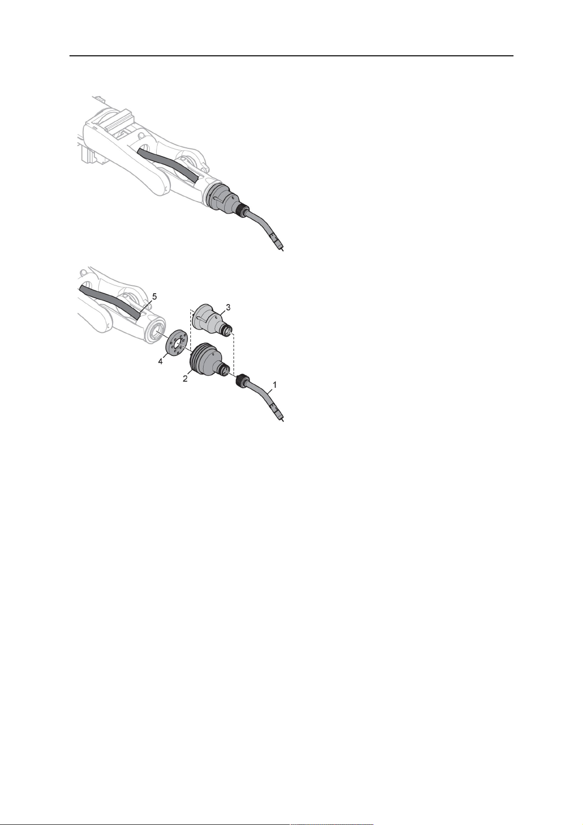
1. For hollow wrist systems, insert the torch into the torch mount in the correct
orientation, so that the locator pin fits into the slot of the RTKSC-2 or RTFLC-2
interface, see (A) in the illustration below. For standard systems, attach the torch to
the RT flange of the cable assembly, (B) in the illustration below.
Installation is only possible in the correct orientation.
2. Tighten the locking nut of the torch neck.
ΣΗΜΕΙΩΣΗ!
Only tighten by hand, never use tools or excessive force.
0463 373 101
- 50 -
© ESAB AB 2018

5 INSTALLATION
3. The correct seating of the torch can be checked by means of the window (1). If the
torch has been correctly mounted, no gap should be seen through the window (1).
5.6 Installing the wire guide for standard and hollow Wrist arm
Installing the wire guide
Choose the wire guide or liner depending on the filler wire material and diameter to be used,
see the spare parts list. Accurate performance of the system can only be guaranteed when
using original ESAB wire guides.
The recommended wire guide is the split wire guide, which consists of the neck liner and a
separate guide in the cable assembly. The front part of the wire guide, which is most
stressed, can be exchanged easily and independently of the cable assembly wire guide.
For correct installation, the following steps must be followed (example for Euro central
connector).
5.6.1 Installing the neck liner
The neck liner must be selected to fit the material and diameter of the welding wire, see the
spare parts list.
0463 373 101
- 51 -
© ESAB AB 2018

5 INSTALLATION
1. If present, remove the central guide nipple (1), from the torch neck using a hexagon
wrench (size 6 mm) or a large flat-blade screwdriver.
ΣΗΜΕΙΩΣΗ!
The guide nipple (1) can only be used with one-piece liners and must not be
used with the standard RT or hollow wrist system.
2. When replacing the neck liner:
Unfasten the sleeve nut and remove the torch neck.
Unfasten the liner nipple using a hexagon wrench (size 6 mm) and remove nipple and
liner from the torch neck.
3. Remove the gas nozzle and the contact tip.
4. Insert the new neck liner (2) into the torch. Carefully tighten the guide nipple using a
suitable tool, e.g. a hex-wrench (size 6 mm) or a large flat-blade screwdriver.
5. Cut the neck liner flush with the tip holder and remove the neck liner from the torch.
6. Install the contact tip.
7. Insert the neck liner again. It will be stopped by the contact tip. Measure the excess
liner sticking out of the neck.
8. Remove the liner again and shorten the front end by the measured length. Carefully
deburr the edge and make sure that the inner hole is not blocked.
9. Reinstall the neck liner and tighten the guide nipple in the neck.
5.6.2 Installing a split wire guide in the cable assembly
The correct liner must be inserted to suit the filler material and the wire diameter, see the
spare parts list.
The wire guide is inserted through the cable assembly from the rear, reaching the guide
nipple that is installed in the flange where the torch neck will be attached. The following
worksteps must be followed in order to correctly determine the wire guide length. (Example
for Euro central connector).
0463 373 101
- 52 -
© ESAB AB 2018
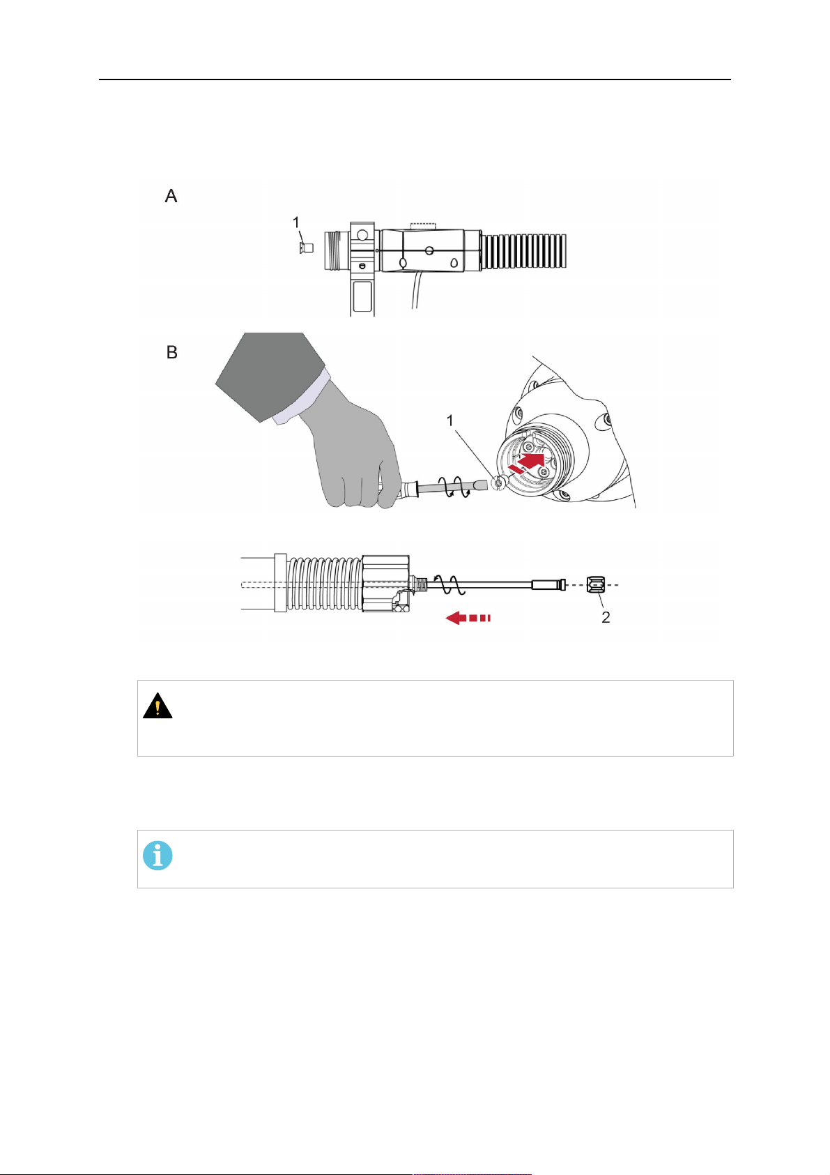
5 INSTALLATION
1. For standard RT system: Install the guide nipple (1) in the center hole of the neck
support flange, see illustration A below.
For hollow wrist system: Install the guide nipple (1) into the torch interface of the
RTKSC-2 / RTFLC-2 cover, see illustration B below.
2. Remove the sleeve nut (2) from the central connector, and remove the old wire guide.
3. Insert the wire guide through the central connection and push forwards as far as it will
go into the guide nipple (1), applying light pressure.
ΠΡΟΣΟΧΗ!
Ensure that the wire guide has advanced right up to the stop at the front,
rotating and pushing forward gently.
4. Measure the excess length that needs to be cut from the wire guide.
5. Remove the wire guide again and shorten the front end by the measured length.
Steel liner: grind down the burred edges if needed.
Plastic liner: make a clean cut and chamfer the edges (e.g. with a pencil sharpener)
ΣΗΜΕΙΩΣΗ!
Make sure the inner opening of the liner is not obstructed by the cut wire end.
0463 373 101
- 53 -
© ESAB AB 2018

5 INSTALLATION
6. Reinstall the wire guide and attach the sleeve nut (2).
ΣΗΜΕΙΩΣΗ!
For hollow wrist systems where Infiniturn and Helix cable assemblies are
used, wire guides should be installed without tension so that the ends of the
liners may rotate freely.
Important note when using a plastic liner:
The wire channel between the drive rolls of the feeder and the central
connector of the torch must be fitted with a plastic liner. Depending on the
design of the feeder, a piece of plastic liner inserted into a brass guide tube
can be used.
During wire run-in, make sure that the wire is fed correctly into the plastic liner
of the torch. If necessary, remove the cable assembly from the feeder and
insert the wire, then reattach.
5.6.3 Installing a continuous wire guide in the cable assembly
Installing a steel liner
The wire guide is inserted through the cable assembly from the rear and reaches to the
contact tip. The following worksteps must be followed for the correct calculation of the length
(example for Euro central connector):
1. Install the torch (see section "Torch neck equipment").
2. Remove the gas nozzle and contact tip from the torch.
3. Remove the sleeve nut (D) from the Euro connector.
4. Push in the liner through the central connector and fix with the sleeve nut.
5. Cut off the liner flush with the nozzle holder. To determine the thread projection of the
contact tip, pull the liner backwards and screw in the contact tip.
6. Push the liner forwards as far as it will go to the contact tip applying light pressure on
the liner and measure the length to be shortened at the rear.
7. Now remove the liner again and cut the excess length measured off it’s front end. If
needed, grind down the burred edges. Make sure the inner opening of the liner is not
obstructed by the cut wire end.
8. The insulation of the liner must be removed after cutting off in the front area, such that
the insulation protrudes out of the RM2 flange by approx. 5 cm. For this, briefly
remove the torch neck.
9. Push the liner back in again and fix with the sleeve nut (D), see above. Re-install the
gas nozzle.
0463 373 101
- 54 -
© ESAB AB 2018

5 INSTALLATION
Installing a plastic liner
1. Mount the torch neck (see section "Torch neck equipment") and equip it with a gas
nozzle and contact tip.
2. Remove the sleeve nut (D) from the Euro connector.
3. Cleanly cut off the liner, slightly break the outer edges, point slightly (e.g. with a pencil
sharpener).
4. Insert the liner through the central connector into the cable assembly with fitted torch.
If it gets stuck, rotate the liner to free it and facilitate installation.
ΣΗΜΕΙΩΣΗ!
Make sure the liner is completely inserted by rotating it and slightly pushing it
forward, until you can feel it has reached its stop.
5. Mount the nipple (B) and the O-Ring (C), move it to the right position and fix it with the
sleeve nut (D) of the Euro central connector.
6. Measure the required overlap needed inside the wire feeder cabinet and cut the liner
accordingly.
5.7 Adjust the narrow gap contact tip
The adjusting tool RT42-NG is designed for the narrow gap torch necks RT42W-NG,
RT42G-NG and RT 82W-0°NG, torches with curved narrow gap contact tip. It facilitates the
precisely repeatable and fast changing of the curved contact tip.
ΣΗΜΕΙΩΣΗ!
The adjusting tool must be securely fastened to a stable base, in order to prevent
the position of the device in relation to the robot cannot change unintentionally. If the
exact orientation of the device is lost, the alignment of the contact tip used for the
elaboration of the welding programs can no longer be reproduced with precision.
Select a position within the operating range of the robot for orientation (alignment) of the
contact tip to the torch. Fasten the adjusting tool firmly to a base using the fastening grooves
provided for this purpose. Fastening material is not included with the adjusting tool. Select
fastening material (screws) to suit the existing conditions.
Save all motion sequences and stop positions required to change or align the wearing parts
to a separate robot program.
Before programming the welding tasks: plan at which orientation the contact tip is to stand in
relation to the torch. The torch must then be positioned in the desired rotational position and
the contact tip aligned using the adjusting device. Only then may the welding task be
programmed. If different orientations of the contact tip are required for various welding tasks,
the contact tip has to be aligned to the new position when the welding task is changed.
ΠΡΟΕΙΔΟΠΟΙΗΣΗ!
The gas nozzle and the torch head become very hot during welding. Always allow
the torch to cool down before replacing wearing parts or adjusting the contact tip.
0463 373 101
- 55 -
© ESAB AB 2018

5 INSTALLATION
Adjust the contact tip
Move the robot torch to a position parallel to
the opening of the adjusting tool (2). Maintain
a sufficient distance to the work table to be
able to comfortably remove the gas nozzle.
Define this position in your robot program as
the wearing parts change position (stop
position 1).
Remove the gas nozzle by pulling it
downwards. Remove the welding wire in the
contact tip if necessary.
Loosen the counter nut (4) of the contact tip
while counter-holding the nozzle holder at the
wrench flat (3).
Unscrew the contact tip including the counter
nut from the nozzle holder and replace the
nozzle holder if necessary.
Completely screw the counter nut (4) onto the
new contact tip. Screw the contact tip
including the counter nut into the nozzle
holder.
Align the contact tip until it is parallel to the
opening of the adjusting tool. If necessary,
slightly unscrew the contact tip so that it can
be easily turned in both directions.
0463 373 101
- 56 -
© ESAB AB 2018

5 INSTALLATION
ΣΗΜΕΙΩΣΗ!
The contact tip must be able to be
easily moved by hand in both
directions in order to enable the
threading of the adjusting tool.
Place the robot torch or contact tip directly in
front of the opening of the adjusting tool (2)
(stop position 2).
Insert it slowly from the front until it is
completely inserted into the device (stop
position 3).
The contact tip was aligned exactly in the
device during insertion. Now cautiously
tighten the counter nut (4) in this position,
while counter holding the nozzle holder at the
wrench flat.
Slowly move the robot torch out of the
adjusting gauge, return to stop position 1 and
push on the gas nozzle as far as it will go.
Allow the welding wire to run into the contact
tip and bring the robot arm into welding
position.
0463 373 101
- 57 -
© ESAB AB 2018

6 OPERATION
6 OPERATION
ΠΡΟΣΟΧΗ!
Before starting the system, check the whole installation according to the
manufacturer's instructions and applicable safety regulations.
Check the following to make sure that the system has been installed correctly:
1. Are all parts securely attached (torch, torch mount, flanges, safety-off device, cable
assembly, and wire feeder cabinet)?
2. Are all media hoses connected correctly and protected from damage?
3. Is the EURO central connector or direct connector fastened tightly?
4. Is the cable assembly length correct and suitable for the installation and can the cable
rotate freely? The cable must not be bent sharply. Any risk of the cable getting caught
on another object must be eliminated.
5. Is the control cable of the safety-off circuit connected and functioning? Move torch by
hand to test (RTKSC-2 and RTKS-2 only).
6. Is the torch firmly attached and is it completely equipped?
7. Is the wire guide installed according to the manual?
8. Are all lines and tubes arranged so that they cannot be damaged or bent?
The wire run-in can now be started, either via the wire run-in pushbutton or via the wire run-in
at the feeder.
6.1 Important information for programming (hollow wrist system only)
Fast rotation of axis 6 of the robot will significantly stress the cable assembly. In certain
cases, this can lead to damage or destruction of the cable. In order to maximize the lifetime
of the cable, we strongly suggest respecting the following limitations when programming the
robot.
Position of axis 5 Max. rotational speed of axis 6
0 – 60° 100 % (no limitations)
60° – 80° 300°/sec (approximately 50 % of max. robot speed)
> 80° 120°/sec (approximately 20 % of max. robot speed)
ΣΗΜΕΙΩΣΗ!
The above values are only indications. For information on the exact rotational speed
limits, refer to the individual robot manual or contact the robot supplier.
To reposition the torch quickly, the robot arm may have to be slightly extended first to achieve
a bending angle of max. 60° of axis 5. In this position, the maximum available rotation speed
of axis 6 can be used.
When using the ESAB Helix cable assembly, the max. rotation of ±270° from the neutral
position must not be exceeded.
0463 373 101
- 58 -
© ESAB AB 2018

6 OPERATION
ΠΡΟΣΟΧΗ!
While axis 5 is bent more than 60°, the rotational speed of the torch around axis 6
must be limited, see table above.
Otherwise, the cable assembly may be damaged.
0463 373 101
- 59 -
© ESAB AB 2018

7 ΣΕΡΒΙΣ ΚΑΙ ΣΥΝΤΗΡΗΣΗ
7 ΣΕΡΒΙΣ ΚΑΙ ΣΥΝΤΗΡΗΣΗ
ΠΡΟΕΙΔΟΠΟΙΗΣΗ!
Πριν από την εκτέλεση εργασιών συντήρησης στο σύστημα, πρέπει να
απενεργοποιηθεί η κεντρική τροφοδοσία ρεύματος της εγκατάστασης. Λάβετε
υπόψη τους κανονισμούς ασφαλείας στην αρχή του παρόντος εγχειριδίου.
Δεν πρέπει να χρησιμοποιούνται φθαρμένες τσιμπίδες ή διατάξεις καλωδίων! Τυχόν
γνωστά ελαττώματα πρέπει να επισκευάζονται από εξειδικευμένο προσωπικό πριν
από την επόμενη χρήση του εξοπλισμού.
ΠΡΟΕΙΔΟΠΟΙΗΣΗ!
Κίνδυνος τραυματισμού από εγκαύματα! Το στόμιο αερίου και η κεφαλή τσιμπίδας
θερμαίνονται πολύ κατά τη διάρκεια των εργασιών συγκόλλησης. Αφήστε την
τσιμπίδα να κρυώσει προτού εκτελέσετε εργασίες συντήρησης.
ΠΡΟΕΙΔΟΠΟΙΗΣΗ!
Για να αποφύγετε τραυματισμούς ή ζημιές στην εγκατάσταση, ακολουθήστε τις
παρακάτω οδηγίες:
1. Η επισκευή της βάσης τσιμπίδας RTKSC-2 ή RTFLC-2, του μηχανισμού
διακοπής ασφαλείας RTKS-2, της διάταξης καλωδίου ή του συνδέσμου
μέσων Infiniturn πρέπει να εκτελείται μόνο από το τμήμα υποστήριξης
σέρβις της ESAB.
2. Ο σύνδεσμος μέσων Infiniturn δεν πρέπει να είναι ποτέ ανοιχτός. Δεν
περιέχει εξαρτήματα που μπορούν να επισκευαστούν από το χρήστη και
θα καταστραφεί σε περίπτωση αποσυναρμολόγησης.
3. Μην αποσυναρμολογείτε ποτέ τις βάσεις RTKSC-2 ή RTKS-2. Αυτός είναι
ένας μηχανισμός με ελατήριο. Τυχόν κακός χειρισμός μπορεί να οδηγήσει
σε σοβαρό τραυματισμό.
7.1 Υποχρεωτικοί έλεγχοι και ενέργειες
Πριν από κάθε χρήση:
• Ελέγξτε την τσιμπίδα, το άκρο επαφής, το στόμιο αερίου, το περίβλημα λαιμού, τα
καλώδια και τον συνολικό εξοπλισμό για γενική ζημιά.
ΣΗΜΕΙΩΣΗ!
Για να ελαχιστοποιήσετε τον χρόνο εκτός λειτουργίας, συνιστάται να κάνετε
εναλλαγή μεταξύ δύο λαιμών τσιμπίδας, έχοντας πάντα έναν πρόσφατα
εξοπλισμένο και έτοιμο για χρήση λαιμό τσιμπίδας.
Κάθε 8 ώρες χρήσης (ανάλογα με την εφαρμογή):
• Αλλάξτε το άκρο επαφής.
Καθημερινά:
• Εκτελέστε λειτουργικό έλεγχο του μηχανισμού διακοπής ασφαλείας με το χέρι.
• Πραγματοποιήστε οπτική επιθεώρηση για ζημιές, π.χ. παραμορφώσεις ή ρωγμές.
• Επιβεβαιώστε τη σωστή θέση της μονάδας τροφοδότησης σύρματος. Η διάταξη
καλωδίου δεν πρέπει να είναι πολύ τεντωμένη ή να κρέμεται.
0463 373 101
- 60 -
© ESAB AB 2018

7 ΣΕΡΒΙΣ ΚΑΙ ΣΥΝΤΗΡΗΣΗ
• Επιθεωρήστε τις συνδέσεις μέσων και τον σύνδεσμο μέσων Infiniturn για τυχόν
διαρροές.
• Εκτελέστε καθαρισμό και συντήρηση της τσιμπίδας σύμφωνα με το εγχειρίδιο χρήσης
της τσιμπίδας.
Κάθε 40 ώρες χρήσης (ανάλογα με την εφαρμογή):
• Αλλάξτε τα περιβλήματα σύρματος.
• Αλλάξτε τα περιβλήματα λαιμού.
Ανά εβδομάδα ή όπως απαιτείται, ανάλογα με τη χρήση:
• Αφαιρέστε τον οδηγό καλωδίων και ελέγξτε για φθορά και εναποθέσεις βρωμιάς.
Αλλάξτε το αν είναι απαραίτητο
Κάθε μήνα ή συχνότερα, σε περίπτωση έντονης χρήσης (δηλ. περισσότερες από 8
ώρες/ημέρα):
• Φυσήξτε το κανάλι οδηγού σύρματος με πεπιεσμένο αέρα (αφαιρέστε το άκρο επαφής
και τον οδηγό σύρματος).
• Βεβαιωθείτε ότι όλες οι βίδες είναι σφιγμένες.
• Ελέγξτε όλα τα καλώδια και τους εύκαμπτους σωλήνες για τυχόν βλάβες.
• Αντικαταστήστε μετά από κάθε 250 kg συγκολλημένου σύρματος.
Τυχόν ζημιά στην ηλεκτρική μόνωση πρέπει να επισκευάζεται από εκπαιδευμένο προσωπικό
για τον ασφαλή χειρισμό του συστήματος.
0463 373 101
- 61 -
© ESAB AB 2018

8 ΑΝΤΙΜΕΤΩΠΙΣΗ ΠΡΟΒΛΗΜΑΤΩΝ
8 ΑΝΤΙΜΕΤΩΠΙΣΗ ΠΡΟΒΛΗΜΑΤΩΝ
Σφάλμα Πιθανή αιτία Ενέργεια
Δεν είναι
δυνατή η
τροφοδοσία του
σύρματος
Το σύρμα συγκόλλησης δεν
ισιώθηκε πριν από την τροφοδοσία
του στη διάταξη καλωδίου
Η τσιμπίδα και η διάταξη καλωδίου
δεν είναι κατάλληλα τοποθετημένες
για τη διάμετρο και το υλικό του
σύρματος
Ο οδηγός σύρματος δεν έχει
τοποθετηθεί σωστά στη διάταξη
καλωδίου
Εάν είναι απαραίτητο, τραβήξτε
ξανά έξω το σύρμα συγκόλλησης,
κόψτε και αφαιρέστε τα γρέζια από
το άκρο και ισιώστε τα πρώτα 10
cm του σύρματος. Στη συνέχεια,
τοποθετήστε ξανά το σύρμα στη
διάταξη καλωδίου.
Ελέγξτε τον οδηγό σύρματος
(διάταξη καλωδίου και λαιμό
τσιμπίδας) καθώς και το άκρο
επαφής.
Τραβήξτε ελαφρώς προς τα έξω τον
οδηγό σύρματος από τον σύνδεσμο
Euro. Κατά την εισαγωγή του
οδηγού σύρματος, θα πρέπει να
αισθανθείτε ότι τα τελευταία
εκατοστά εισέρχονται μέσα στο
προστόμιο-οδηγό στη διεπαφή της
τσιμπίδας. Διαφορετικά, ο οδηγός
σύρματος μπορεί να είναι πολύ
κοντός και να μην έχει εισαχθεί
πλήρως.
Η τσιμπίδα
υπερθερμαίνετα
ι
Το άκρο επαφής έχει φράξει από
υπολείμματα σύρματος
Ο οδηγός σύρματος έχει φθαρεί
Το καλώδιο τροφοδοσίας
εμποδίζεται από βρωμιά και
κατάλοιπα μέσα στην τσιμπίδα
Το άκρο επαφής ή η βάση άκρου
δεν είναι αρκετά σφιγμένα
Το σύστημα ψύξης δεν λειτουργεί
καλά
Το σύστημα ψύξης δεν είναι
συνδεδεμένο σωστά.
Υπάρχει υπερβολική καταπόνηση
της τσιμπίδας
Η διάταξη καλωδίου είναι
ελαττωματική
Αντικαταστήστε το άκρο επαφής
ή/και τον οδηγό σύρματος και
φυσήξτε τον λαιμό της τσιμπίδας,
τον αγωγό οδηγού σύρματος και
τον οδηγό σύρματος με πεπιεσμένο
αέρα.
Χρησιμοποιήστε ένα κατάλληλο
εργαλείο για σφίξιμο με το χέρι.
Ελέγξτε τη ροή νερού, τη στάθμη
πλήρωσης και την καθαρότητα.
Ελέγξτε τις συνδέσεις (είσοδος και
επιστροφή νερού).
Τηρήστε τα τεχνικά στοιχεία και,
εφόσον απαιτείται, επιλέξτε
διαφορετικό τύπο.
Ελέγξτε τα καλώδια, τους σωλήνες
και τις συνδέσεις.
0463 373 101
- 62 -
© ESAB AB 2018

8 ΑΝΤΙΜΕΤΩΠΙΣΗ ΠΡΟΒΛΗΜΑΤΩΝ
Σφάλμα Πιθανή αιτία Ενέργεια
Προβλήματα
τροφοδότησης
σύρματος
Η τροφοδότηση
σύρματος
σταματά στη
διάρκεια της
συγκόλλησης
Το άκρο επαφής είναι φθαρμένο Αλλάξτε άκρο επαφής.
Το περίβλημα είναι
φθαρμένο/βρώμικο
Τα αναλώσιμα που
χρησιμοποιούνται δεν είναι
Ελέγξτε το περίβλημα και φυσήξτε
το. Αλλάξτε το αν είναι απαραίτητο
Συμβουλευτείτε τη λίστα
ανταλλακτικών.
κατάλληλα για τη διάμετρο ή το
υλικό του σύρματος
Η μονάδα τροφοδότησης σύρματος
δεν έχει ρυθμιστεί σωστά
Ελέγξτε τους κυλίνδρους
τροφοδότησης σύρματος, την πίεση
επαφής και το φρένο του καρουλιού
σύρματος.
Η διάταξη καλωδίου είναι λυγισμένη
ή απλωμένη σε πολύ μικρή ακτίνα.
Ελέγξτε τη διάταξη καλωδίου για
τυχόν ζημιές. Το περίβλημα
τοποθετείται εύκολα; Εγκαταστήστε
το σύμφωνα με τις οδηγίες.
Ανατρέξτε στην ενότητα
"Εγκατάσταση της διάταξης
καλωδίου".
Το σύρμα είναι λερωμένο Χρησιμοποιήστε τσόχα καθαρισμού.
Το καρούλι σύρματος είναι άδειο Ελέγξτε την ποσότητα του
σύρματος συγκόλλησης στο
καρούλι της μονάδας τροφοδότησης
σύρματος.
Μπλοκάρισμα των συρμάτων στη
διάταξη καλωδίου
Ελέγξτε την τροφοδοσία του
καλωδίου (γίνεται ενδεχομένως
πολύ γρήγορα), ελέγξτε το άκρο
επαφής για ακαθαρσίες/φράξιμο και
καθαρίστε ή αντικαταστήστε το, εάν
χρειαστεί.
Η καύση του σύρματος καθυστερεί
στο άκρο επαφής ή το άκρο επαφής
είναι φθαρμένο
Η διεργασία
συγκόλλησης
Έχει ενεργοποιηθεί ο μηχανισμός
διακοπής ασφαλείας.
διακόπτεται
Πόροι στη ραφή Δίνη αερίου που προκλήθηκε από
προσκόλληση πιτσιλισμάτων
Πολύ μικρή ή υπερβολικά υψηλή
ροή αερίου στην τσιμπίδα
Ελαττωματική παροχή αερίου Ελέγξτε τον ρυθμό ροής και το
Υγρασία ή ρύποι στο σύρμα ή στο
τεμάχιο εργασίας
Αντικαταστήστε το άκρο επαφής.
Ελέγξτε για τυχόν σημεία
πρόσκρουσης και αποτρέψτε τα.
Ελέγξτε τη γραμμή ελέγχου για
χαλαρή επαφή.
Καθαρίστε την κεφαλή της
τσιμπίδας, χρησιμοποιώντας
προστασία από πιτσιλίσματα /
διασπορά αερίου.
Ελέγξτε τον ρυθμό ροής με ένα
εργαλείο μέτρησης.
ενδεχόμενο διαρροής.
Ελέγξτε το σύρμα και το τεμάχιο
εργασίας, χρησιμοποιήστε λιγότερο
ή διαφορετικό υγρό προστασίας
από πιτσιλίσματα.
0463 373 101
- 63 -
© ESAB AB 2018

8 ΑΝΤΙΜΕΤΩΠΙΣΗ ΠΡΟΒΛΗΜΑΤΩΝ
Σφάλμα Πιθανή αιτία Ενέργεια
Το τόξο δεν
είναι σταθερό
Το άκρο επαφής είναι φθαρμένο Αλλάξτε άκρο επαφής.
Λανθασμένες παράμετροι
συγκόλλησης
Ανεπαρκείς ηλεκτρικές συνδέσεις
στο κύκλωμα
Ελέγξτε την εγκατάσταση του
εξοπλισμού συγκόλλησης.
Ελέγξτε όλες τις ηλεκτρικές
συνδέσεις (συμπεριλαμβανομένου
του καλωδίου γείωσης) μεταξύ της
πηγής ισχύος της τσιμπίδας ή του
τεμαχίου εργασίας για να δείτε αν
είναι τοποθετημένες σωστά.
0463 373 101
- 64 -
© ESAB AB 2018

9 ΠΑΡΑΓΓΕΛΙΑ ΑΝΤΑΛΛΑΚΤΙΚΩΝ
9 ΠΑΡΑΓΓΕΛΙΑ ΑΝΤΑΛΛΑΚΤΙΚΩΝ
ΠΡΟΣΟΧΗ!
Η επισκευή και η εργασία στο ηλεκτρικό μέρος θα πρέπει να γίνονται από
εξουσιοδοτημένο τεχνικό σέρβις της ESAB. Χρησιμοποιείτε μόνο γνήσια ανταλλακτικά
και φθειρόμενα μέρη της ESAB.
Οι τσιμπίδες RTKS-2, RTFL-2, RT-KSC-2, RT-FLC-2, RT42, RT52, RT62, RT72, RT82,
RT42-NG και RT82WNG έχουν σχεδιαστεί και ελεγχθεί σύμφωνα με τα Διεθνή και
Ευρωπαϊκά Πρότυπα IEC/EN 60974-7. Είναι υποχρέωση της μονάδας συντήρησης που
εκτελεί την εργασία συντήρησης ή επισκευής να εξασφαλίζει ότι το προϊόν συνεχίζει να
συμμορφώνεται με τα εν λόγω πρότυπα.
Μπορείτε να παραγγείλετε ανταλλακτικά και αναλώσιμα από τον πλησιέστερο αντιπρόσωπο
της ESAB. Ανατρέξτε στη διεύθυνση esab.com. Όταν παραγγέλλετε, παρακαλούμε
αναφέρετε τύπο προϊόντος, αριθμό σειράς, χαρακτηρισμό και αριθμό ανταλλακτικού
σύμφωνα με τον κατάλογο ανταλλακτικών. Αυτό διευκολύνει την αποστολή και διασφαλίζει τη
σωστή παράδοση.
0463 373 101
- 65 -
© ESAB AB 2018

ESAB AB, Lindholmsallén 9, Box 8004, 402 77 Gothenburg, Sweden, Phone +46 (0) 31 50 90 00
http://manuals.esab.com
For contact information visit esab.com
 Loading...