


RT Robo Welding Torch System
RTKS-2, RTFL-2, KSC-2, FLC-2, RT42, RT52,
RT62, RT72, RT82, RT42-NG, RT82WNG
Návod k používání
0463 373 101 CZ 20181227


OBSAH
1
BEZPEČNOST............................................................................................. 5
1.1 Vysvětlení symbolů ................................................................................ 5
1.2 Bezpečnostní opatření ........................................................................... 5
2
ZÁRUKA ...................................................................................................... 8
2.1 Podmínky splňující účel použití............................................................ 8
3
ÚVOD ........................................................................................................... 9
3.1 Přehled systémů svařovacích hořáků.................................................. 9
4
TECHNICKÉ ÚDAJE ................................................................................... 11
4.1 Hrdlo svařovacího hořáku ..................................................................... 11
4.2 Jmenovité napětí .................................................................................... 12
4.2.1 Omezení chladicího okruhu.................................................................. 13
4.3 Úchyt hořáku........................................................................................... 13
4.3.1 Úchyty hořáku pro standardní systémRT ............................................ 13
4.3.1.1 Bezpečnostní vypínací mechanismusRT KS-2 ................................ 14
4.3.1.2 Mezilehlá přírubaRTFL-2................................................................. 14
4.3.2 Úchyty hořáku pro systém sdutým zápěstím....................................... 15
4.3.2.1 Úchyt hořákuRT KSC-2 G/W sbezpečnostním vypínacím
mechanismem ...................................................................................
4.3.2.2 Pevný úchyt pro hořákRT FLC-2 G/W.............................................. 17
4.4 Přírubové adaptéry................................................................................. 18
4.5 Kabelové sestavy ................................................................................... 18
4.5.1 Kabelové sestavy pro standardní systémRT....................................... 18
4.5.2 Kabelové sestavy pro systémy sdutým zápěstím................................ 19
5
INSTALLATION............................................................................................ 21
5.1 RTKS-2 standard arm installation........................................................ 21
5.1.1 RTKS-2 safety-off mechanism............................................................. 21
5.1.1.1 Torch installation with adjustable mount............................................ 22
5.1.2 Standard arm cable assembly for KS-2 and FL-2 ................................ 24
5.1.3 RTKS-2 wire feeder connection........................................................... 25
5.1.4 RTKS-2 electrical connections ............................................................ 26
5.1.4.1 RTKS-2 safety-off mechanism connection ....................................... 26
5.1.5 RTKS-2 Torch installation .................................................................... 27
5.2 RTFL-2 standard arm installation ........................................................ 28
16
5.2.1 RTFL-2 rigid mount.............................................................................. 28
5.2.2 RTFL-2 torch installation ..................................................................... 30
5.3 RTKSC-2 hollow wrist system installation.......................................... 30
5.3.1 RTKSC-2 mount with safety off mechanism........................................ 30
5.3.2 Mounting the cable assembly............................................................... 31
5.3.2.1 RTKSC-2 feeder cabinet connections .............................................. 32
5.3.3 RTKSC-2 cable assembly ................................................................... 34
5.3.3.1 RTKSC-2 cable assembly installation .............................................. 34
0463 373 101 © ESAB AB 2018

OBSAH
5.3.3.2 RTKSC-2 electrical connections....................................................... 37
5.3.4 RTKSC-2 torch installation .................................................................. 38
5.4 RTFLC-2 installation.............................................................................. 39
5.4.1 RTFLC-2 mount................................................................................... 39
5.4.2 RTFLC-2 wire feeder connection......................................................... 39
5.4.2.1 Feeding through the robot arm.......................................................... 39
5.4.2.2 RTFLC-2 feeder cabinet connections............................................... 40
5.4.3 RTFLC-2 cable assembly .................................................................... 42
5.4.3.1 RTFLC-2 cable assembly installation ............................................... 42
5.4.4 RTFLC-2 electrical connections .......................................................... 45
5.4.4.1 RTFLC-2 hollow wrist system with Infiniturn cable assembly........... 45
5.4.4.2 RTFLC-2 hollow wrist system with Helix cable assembly................. 46
5.5 Torch installation.................................................................................... 46
5.5.1 Torch neck equipment .......................................................................... 46
5.5.2 Aristo RT torch neck installation........................................................... 47
5.6 Installing the wire guide for standard and hollow Wrist arm ............. 48
5.6.1 Installing the neck liner......................................................................... 48
5.6.2 Installing a split wire guide in the cable assembly ................................ 49
5.6.3 Installing a continuous wire guide in the cable assembly ..................... 51
5.7 Adjust the narrow gap contact tip ........................................................ 52
6
OPERATION ................................................................................................ 55
6.1 Important information for programming (hollow wrist system only) 55
7
SERVIS AÚDRŽBA..................................................................................... 57
7.1 Povinné kontroly aakce ........................................................................ 57
8
ŘEŠENÍ PROBLÉMŮ .................................................................................. 59
9
OBJEDNÁVÁNÍ NÁHRADNÍCH DÍLŮ ........................................................ 61
Práva ke změně technických údajů bez upozornění vyhrazena.
0463 373 101 © ESAB AB 2018

1 BEZPEČNOST
1 BEZPEČNOST
1.1 Vysvětlení symbolů
Vtomto návodu se symboly používají vnásledujícím významu: Znamená Pozor! Buďte
pozorní!
NEBEZPEČÍ!
Označuje bezprostřední nebezpečí. Pokud se mu nevyhnete, povede
kokamžitému a vážnému zranění osob nebo smrti.
VAROVÁNÍ!
Označuje potenciální nebezpečí, které může vést ke zranění osob nebo
smrti.
UPOZORNĚNÍ!
Označuje nebezpečí, které může vést kméně závažnému zranění osob.
VAROVÁNÍ!
Před používáním si přečtěte návod kobsluze a snažte
se mu porozumět, řiďte se všemi výstražnými štítky,
bezpečnostními předpisy zaměstnavatele a
bezpečnostními listy (SDS).
1.2 Bezpečnostní opatření
Uživatelé zařízení ESAB nesou konečnou odpovědnost za to, že zajistí, aby každý, kdo
pracuje stakovým zařízením nebo vjeho blízkosti, dodržoval všechna příslušná
bezpečnostní opatření. Bezpečnostní opatření musí vyhovovat požadavkům vztahujícím se
na tento typ zařízení. Kromě standardních nařízení, která platí pro dané pracoviště, je nutno
dodržovat i níže uvedená doporučení.
Veškeré práce musí provádět kvalifikovaní pracovníci, kteří jsou dobře obeznámeni
sobsluhou zařízení. Nesprávná obsluha zařízení může vést knebezpečným situacím, které
mohou mít za následek zranění obsluhy a poškození zařízení.
1. Každý, kdo používá toto zařízení, musí být dobře obeznámen s:
○ obsluhou zařízení;
○ umístěním nouzových vypínačů;
○ fungováním zařízení;
○ příslušnými bezpečnostními opatřeními;
○ svařováním a řezáním nebo jiným příslušným použitím vybavení
2. Obsluha zařízení musí zajistit, aby:
○ při spuštění zařízení nebyla vjeho pracovním prostoru žádná neoprávněná
osoba
○ při zapálení oblouku a zahájení svařování byly všechny osoby chráněny
3. Pracoviště musí být:
○ vhodné kdanému účelu;
○ bez průvanu.
0463 373 101
- 5 -
© ESAB AB 2018

1 BEZPEČNOST
4. Osobní ochranné prostředky:
○ Vždy používejte osobní ochranné prostředky, jako jsou ochranné brýle, oděv
odolný proti ohni a ochranné rukavice
○ Nenoste volné doplňky či ozdoby, jako jsou šály, náramky, prsteny atd., které by
se mohly zachytit nebo způsobit popáleniny
5. Obecná bezpečnostní opatření:
○ Přesvědčte se, zda je zpětný vodič bezpečně připojen
○ Práci na vysokonapěťovém zařízení smí provádět pouze kvalifikovaný
elektrikář
○ Kdispozici musí být vhodný a jasně označený hasicí přístroj
○ Mazání a údržba zařízení se nesmí provádět za provozu.
VAROVÁNÍ!
Svařování ařezání obloukem může být nebezpečné pro vás ipro jiné osoby. Při
svařování nebo řezání dodržujte bezpečnostní opatření.
ÚRAZ ELEKTRICKÝM PROUDEM – může způsobit smrt
• Nainstalujte a uzemněte jednotku vsouladu snávodem kobsluze.
• Nedotýkejte se elektrických dílů pod napětím nebo elektrod holou kůží,
vlhkými rukavicemi nebo vlhkým oděvem.
• Izolujte se od země a svařovaného předmětu.
• Dbejte na bezpečnou pracovní polohu
ELEKTRICKÁ A MAGNETICKÁ POLE – mohou být zdraví nebezpečná
• Svářeči skardiostimulátorem se musí před svářením obrátit na svého
lékaře. Elektrická a magnetická pole mohou ovlivňovat funkci některých
kardiostimulátorů.
• Elektrická a magnetická pole mohou mít jiné neznámé vlivy na zdraví.
• Je třeba, aby svářeči dodržovali následující opatření a minimalizovali vliv
elektromagnetických polí:
○ Veďte elektrodu a pracovní vodiče společně po stejné straně těla.
Pokud je to možné, zajistěte je páskou. Nezdržujte se mezi hořákem
a pracovními kabely. Nikdy nenamotávejte hořák nebo pracovní kabel
na tělo. Zdržujte se co nejdále od zdroje pro svařování a kabelů.
○ Připojte pracovní kabel kobrobku co nejblíže ke svařovanému místu.
VÝPARY APLYNY – mohou být zdraví nebezpečné
• Kryjte si hlavu před výpary.
• Použijte odvětrávání, odsávání u oblouku nebo obojí k odvádění par a
plynů ze své dýchací zóny a všeobecného prostoru.
OBLOUKOVÉ ZÁŘENÍ – může poranit oči a spálit kůži
• Chraňte si oči atělo. Používejte správný ochranný štít, brýle sfiltračními
skly aochranný oděv.
• Osoby nacházející se vblízkosti chraňte vhodnými štíty nebo clonami.
0463 373 101
HLUK – nadměrný hluk může poškodit sluch
Chraňte si uši. Používejte protihluková sluchátka nebo jinou ochranu sluchu.
- 6 -
© ESAB AB 2018

1 BEZPEČNOST
POHYBLIVÉ DÍLY – mohou způsobit zranění
• Udržujte všechny panely, kryty a dveře zavřené a zajištěné. Pouze
proškolený personál smí vpřípadě potřeby odstraňovat kryty za účelem
údržby a odstraňování poruch. Po dokončení servisu a před začátkem
sváření vraťte všechny panely nebo kryty na místo a zavřete všechny
dveře.
• Před montáží nebo připojením jednotky vypněte motor.
• Zajistěte, aby se do dosahu pohyblivých částí nedostaly ruce, vlasy, volné
oblečení a nástroje.
NEBEZPEČÍ POŽÁRU
• Jiskry (prskání) mohou způsobit požár. Zajistěte, aby se v blízkosti
nenacházely žádné hořlavé materiály.
• Nepoužívat na uzavřené kontejnery.
FUNKČNÍ PORUCHA – při funkční poruše požádejte oodbornou pomoc.
CHRAŇTE SEBE I JINÉ!
UPOZORNĚNÍ!
Tento výrobek je určen výhradně ksvařování obloukem.
VAROVÁNÍ!
Nepoužívejte tento zdroj energie k rozmrazování zamrzlého potrubí.
UPOZORNĚNÍ!
Zařízení třídy A není určeno kpoužívání vobytných
oblastech, vnichž je elektrické napájení zajišťováno
veřejnou, nízkonapěťovou rozvodnou sítí. Kvůli rušení
šířenému vedením a vyzařováním se mohou vtakových
oblastech objevit případné obtíže se zaručením
elektromagnetické kompatibility u zařízení třídy A.
POZOR!
Elektronická zařízení likvidujte v recyklačním
zařízení!
V souladu s evropskou směrnicí 2012/19/ES o likvidaci
elektrických a elektronických zařízení a její
implementací podle státních zákonů se musí elektrické
zařízení, které dosáhlo konce životnosti, zlikvidovat v
recyklačním zařízení.
Jako osoba zodpovědná za zařízení máte povinnost
informovat se o schválených sběrných místech.
Chcete-li další informace, obraťte se na nejbližšího
prodejce společnosti ESAB.
ESAB nabízí řadu přídavných zařízení pro svařování a osobních ochranných
prostředků. Informace pro objednávání vám poskytne váš lokální prodejce ESAB nebo
naše webová stránka.
0463 373 101
- 7 -
© ESAB AB 2018

2 ZÁRUKA
2 ZÁRUKA
Před dodáním procházejí naše produkty pečlivou kontrolou. Společnost ESAB ověřuje, že
vdobě dodávky je každý produkt vbezvadném stavu, pokud jde omateriál azpracování,
afunguje vsouladu súčelem použití.
Společnost ESAB poskytuje záruku na závady materiálu aprovedení vsouladu
slegislativními požadavky. Na spotřební materiál se tato záruka nevztahuje.
Záruka nepokrývá žádné škody ani funkční závady vzniklé následkem:
• přetížení, nesprávného použití produktu či použití odchylujícího se od účelu použití,
• kolizí či nehod,
• nedodržování pokynů uvedených vtomto návodu kobsluze,
• nesprávné instalace či montáže,
• nedostatečné údržby,
• modifikace původního stavu produktu,
• působení chemikálií,
• běžného opotřebení.
Společnost ESAB nese odpovědnost pouze za výměnu či opravu vadných dílů.
2.1 Podmínky splňující účel použití
1. Produkt je určen kprůmyslovému akomerčnímu použití asmí jej používat pouze
školený personál. Výrobce neodpovídá za škody či nehody způsobené nesprávným
použitím.
2. Robotický svařovací systém Aristo®RT je navržen avyráběn na špičkové úrovni
místech apři manipulaci, instalaci aúdržbě školeným personálem je bezpečný
aspolehlivý. Je nutné dodržovat pokyny pro instalaci, provoz aúdržbu popsané
vtomto dokumentu.
3. Robotický svařovací systém Aristo®RT smí instalovat, obsluhovat aservisovat pouze
školený personál. Je nutné dodržovat předpisy oinstalaci, obsluze aúdržbě, které
jsou podrobně popsány vtéto příručce.
4. Robotický svařovací systém Aristo®RT se smí používat výhradně pro účely určené
výrobcem vrámci technických údajů aspolu sautomatizovanými systémy na
manipulaci. Typ hořáku je nutné zvolit tak, aby odpovídal svařovacímu úkolu.
5. Robotický svařovací systém Aristo®RT byl zkonstruován kpoužití jako ucelený
systém. Do systému není dovoleno včleňovat součástky od jiných výrobců.
6. SystémyRT KS-2 aRT KSC-2 lze použít pouze jako mechanismy nouzového
zastavení vrámci jejich technických specifikací avkombinaci se standardní sestavou
kabelového rameneRT (KS-2), Infiniturn nebo Helix (KSC-2), přírubovým adaptérem
ESAB, včetně úchytů hořákuRT (KS-2) asvařovacího hořáku AristoRT.
7. Do profukovacího plynu se nesmí přidávat olej ani kapalina proti rozstřiku. Společnost
ESAB nezaručuje chemickou odolnost vůči těmto látkám. Společnost ESAB
doporučuje použít postřikovací jednotku ESAB kaplikaci minimálního množství
kapaliny proti rozstřiku na hořák, což přispívá kochraně životního prostředí.
8. Produkt je nutné během přepravy, skladování apoužívání uchovávat vsuchu achránit
před vlhkostí.
9. Systém byl navržen pro provozní teploty vrozmezí od 5°C do 40°C (41F až
104°F). Při překročení těchto limitních hodnot je nutné provést konkrétní kroky. Pokud
hrozí nebezpečí mrazu, použijte vhodnou chladicí směs.
0463 373 101
- 8 -
© ESAB AB 2018

3 ÚVOD
3 ÚVOD
Systémy svařovacího hořákuRT jsou vyvinuty kplně automatickému svařování MIG/MAG za
použití svařovacích robotů. Systémy se skládají zřady hrdel hořáku AristoRT určených pro
robotické použití, úchytů hořáku, kabelových sestav optimalizovaných pro robotické použití
abezpečnostních prvků, které zabraňují poškození systému vpřípadě kolize.
Standardní svařovací systémRT zajišťuje ochranu proti kolizi pomocí zařízeníRT KS-2, což
je mechanická pružinová bezpečnostní funkce. Tuto funkci lze volitelně nahradit
systémemRTFL-2, který využívá funkci detekce kolize zřídicího systému robota.
Standardní svařovací systémRT lze použít srůznými typy kabelových sestav.
Úchyty hořákuRTKSC-2 aRTFLC-2 skabelovými sestavami Infiniturn nebo Helix jsou
určeny pro použití vrobotických svařovacích systémech sdutým zápěstím, které jsou určeny
pro pokročilé aplikace svařování. Bezpečnostní vypínací mechanismus vúchytu hořákuRT
KSC-2 nabízí velkou elastickou deformaci hořáku vpřípadě kolize. Kabelové sestavy
Infiniturn aHelix se snadno instalují aposkytují vysoce spolehlivý systém spřesnými
manévrovacími schopnostmi.
Vkombinaci sosvědčenými robotickými svařovacími hořáky AristoRT vytvářejí tyto složky
vysoce spolehlivý atrvanlivý systém, který vyžaduje pouze minimální údržbu.
Návod kpoužití je součástí dodávky úchytů hořáku akabelových sestav.
Objednací čísla ESAB, dostupné příslušenství, náhradní díly aspotřební díly jsou
uvedeny vseznamu náhradních dílů.
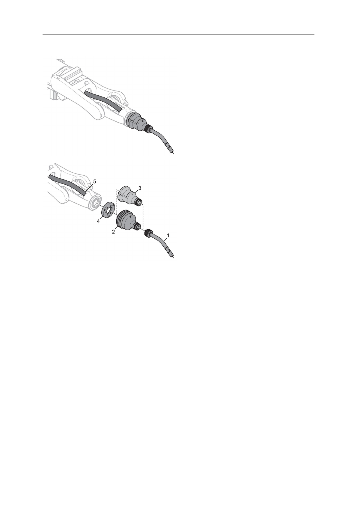
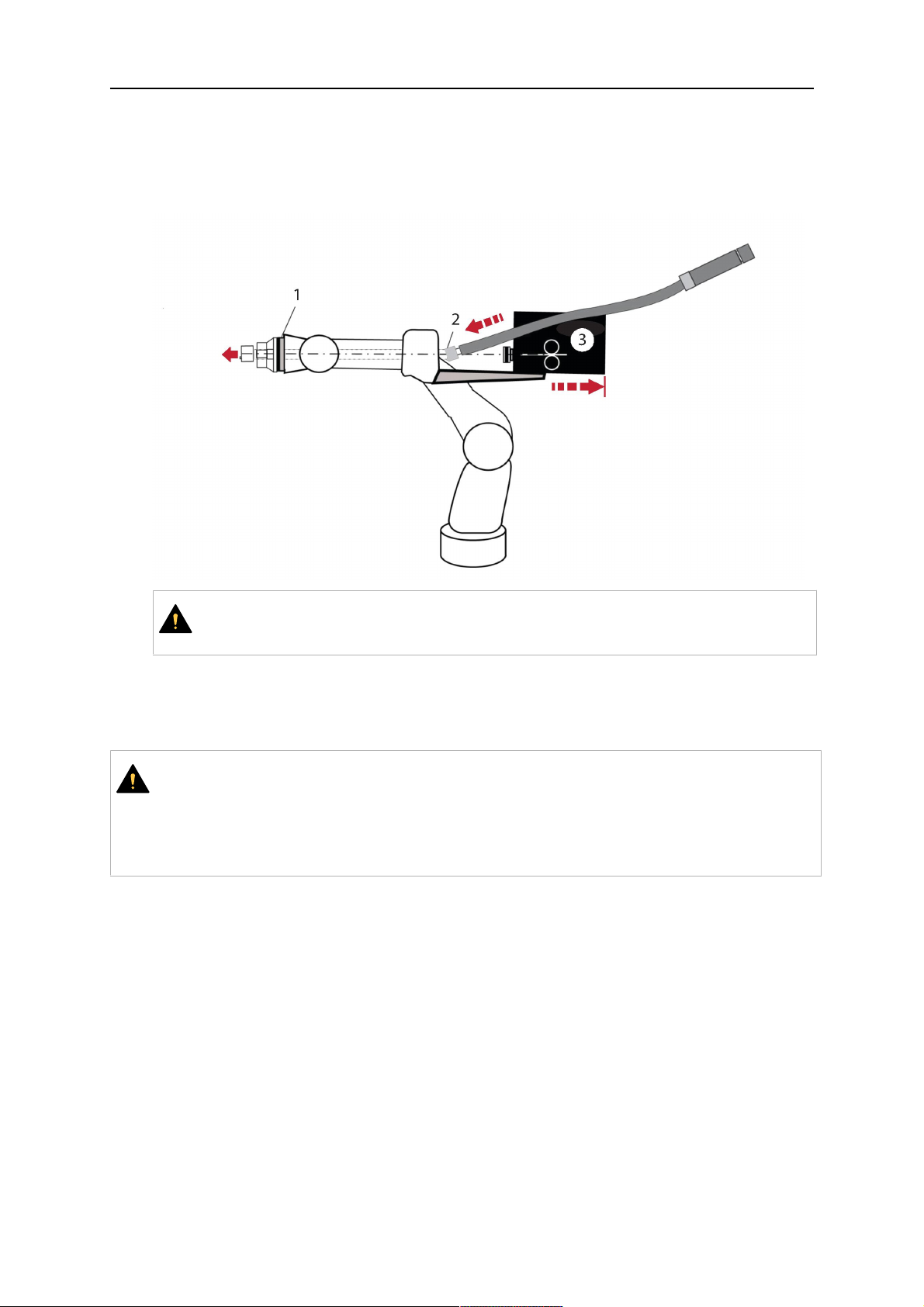
3.1 Přehled systémů svařovacích hořáků
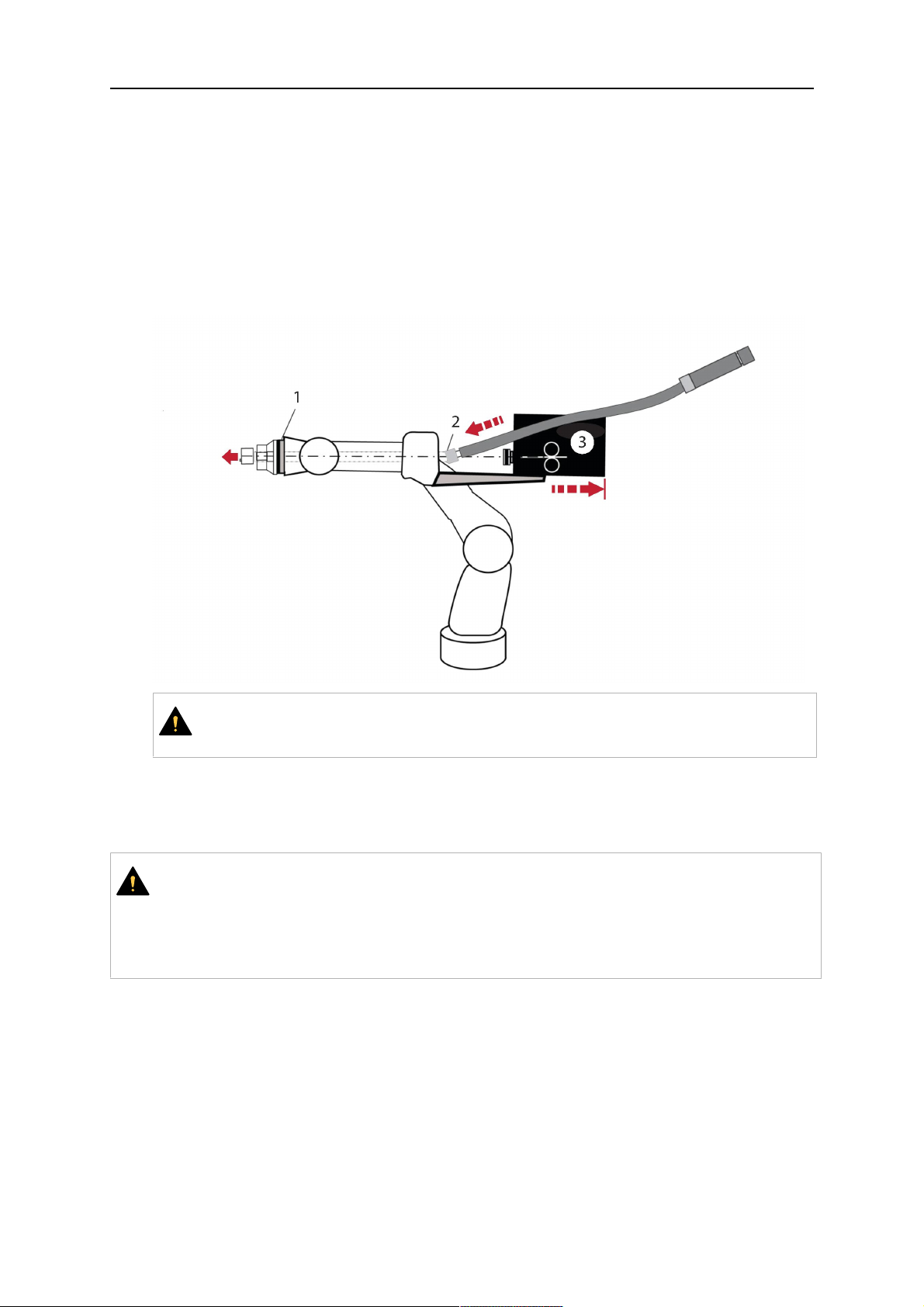
Standardní systémRT
Podrobný popis naleznete vpříslušné části
vkapitole TECHNICKÉ ÚDAJE:
1. Hrdlo hořáku
Viz „Svařovací hořák“.
2. Kabelová sestava
Viz „Kabelové sestavy pro
standardní systémRT“.
3. Úchyt hořáku
Viz „Úchyty hořáku pro standardní
systémRT“.
4. Bezpečnostní vypínací
mechanismusRT KS-2
Viz „Bezpečnostní vypínací
mechanismusRT KS-2“.
5. Mezilehlá přírubaRTFL-2
Viz „Mezilehlá příruba RT FL-2“.
6. Přírubový adaptér (je-li vyžadován)
Viz „Přírubový adaptér“.
0463 373 101
- 9 -
© ESAB AB 2018
3 ÚVOD
Systém sdutým zápěstím
Podrobný popis naleznete vpříslušné části
vkapitole TECHNICKÉ ÚDAJE:
1. Hrdlo hořáku
Viz „Svařovací hořák“.
2. Úchyt hořákuRT KSC-2
Viz „Úchyt hořákuRT KSC-2
sbezpečnostním mechanismem“.
3. Úchyt hořákuRT FLC-2
Viz „Pevný úchyt hořákuRT FLC-2“.
4. Přírubový adaptér
Viz „Přírubový adaptér“.
5. Kabelová sestava Helix nebo
Infiniturn
Viz „Kabelové sestavy pro systémy
sdutým zápěstím“.
0463 373 101
- 10 -
© ESAB AB 2018

4 TECHNICKÉ ÚDAJE
4 TECHNICKÉ ÚDAJE
4.1 Hrdlo svařovacího hořáku
Zvolte si model hořáku podle svářecí aplikace. Je nutné vzít vúvahu požadovaný pracovní
cyklus akapacitu, metodu chlazení aprůměr drátu. Vpřípadě vyšších nároků, například
následkem předehřátých obrobků, vysokého odrazu tepla vrozích atd., je nutné je vzít
vúvahu avybrat svařovací hořák sadekvátní rezervou jmenovitého výkonu.
Svařovací hořákyRT jsou určeny kpoužití snapájecími zdroji pro svařování označenými
značkou CE aurčenými kprocesům svařování kovů za použití inertního plynu (MIG),
aktivního plynu (MAG) apájení kovů na tvrdo (MIG Brazing) za použití komerčních drátů
kruhového průřezu. Hořák nepoužívejte kjiným procesům.
Při svařování oceli nebo hliníku impulzním obloukem je nutné použít vodou chlazený
hořákRT 82 W.
Viz dostupné modely hořáků níže.
Model hořáku Metoda chlazení Ochranný plyn Zatížitelnost
RT42G Chlazený plynem CO
Chlazený plynem 300A/100%
Chlazený plynem Mix 350A/60%
Chlazený plynem 250A/100%
RT42W Chlazený vodou CO
Chlazený vodou 420A/100%
Chlazený vodou Mix 350A/60%
Chlazený vodou 350A/100%
RT52G Chlazený plynem CO
Chlazený plynem 300A/100%
Chlazený plynem Mix 350A/60%
Chlazený plynem 250A/100%
RT52W Chlazený vodou CO
Chlazený vodou 470A/100%
Chlazený vodou Mix 400A/60%
Chlazený vodou 400A/100%
RT62G Chlazený plynem CO
Chlazený plynem 340A/100%
2
2
2
2
2
420A/60%
420A/60%
420A/60%
470A/60%
500A/60%
Chlazený plynem Mix 420A/60%
Chlazený plynem 290A/100%
RT62W Chlazený vodou CO
Chlazený vodou 530A/100%
Chlazený vodou Mix 450A/60%
Chlazený vodou 450A/100%
0463 373 101
- 11 -
2
530A/60%
© ESAB AB 2018

4 TECHNICKÉ ÚDAJE
Model hořáku Metoda chlazení Ochranný plyn Zatížitelnost
RT72G Chlazený plynem CO
2
480A/60%
Chlazený plynem 320A/100%
Chlazený plynem Mix 400A/60%
Chlazený plynem 270A/100%
RT72W Chlazený vodou CO
2
480A/60%
Chlazený vodou 430A/100%
Chlazený vodou Mix 480A/60%
Chlazený vodou 430A/100%
RT82W Chlazený vodou CO
2
600A/60%
Chlazený vodou 600A/100%
Chlazený vodou Mix 550A/60%
Chlazený vodou 550A/100%
Hodnoty jmenovitého výkonu hořáku apracovního cyklu jsou platné po dobu 10minut cyklu.
Technické údaje platí pro standardizované aplikace využívající standardní spotřební nebo
náhradní díly. Při použití režimu přenosu kovu impulzním obloukem je snížen jmenovitý
výkon hořáku.
Rozsahy teplot Skladování: -15-50°C (5-122°F)
Provoz: 5–40°C (41–104°F)
Profukovací plyn Max. 10barů, samostatná plynová hadice
Celková hmotnost (hrdlo hořáku,
Přibližně 5kg
bezpečnostní mechanismus, úchyt hořáku
a1m kabelová sestava)
4.2 Jmenovité napětí
Max. přípustné napětí/ proud
Kompletní systém svařovacích hořáků 141V(špičková hodnota pro svařování)
Řídicí obvod bezpečnostního vypnutíRT
KS-2
TlačítkoRT KS-2
Řídicí obvod bezpečnostního vypnutíRT
KSC-2
Použití funkce snímání hubice se standardní
kabelovou sestavou
Použití funkce snímání hubice skabelovými
sestavami Helix nebo Infiniturn
24V/ 1A
48V/0,1A
48 V
50V/ 5A
(Přípustné zatížení max. 1minuta při
jmenovitém proudu)
50V/ 5A
(Přípustné zatížení max. 1minuta při
jmenovitém proudu)
Uvedený jmenovitý výkon se vztahuje na standardizovaný případ použití.
Jmenovité hodnoty pro kabelové sestavy naleznete včásti „Kabelové sestavy“.
0463 373 101
- 12 -
© ESAB AB 2018

4 TECHNICKÉ ÚDAJE
4.2.1 Omezení chladicího okruhu
Platí pouze pro vodou chlazené verze.
Min. rychlost průtoku vody: 1,0l/min(1,1kvartu/min)
Min. tlak vody: 2,5baru (36,3PSI)
Max. tlak vody: 3,5baru (50,8PSI)
Sací teplota: Max. 40°C(104°F)
Teplota zpětné vody: Max. 60°C (140°F)
Chladicí výkon: Min. 1000W, vzávislosti na aplikaci
UPOZORNĚNÍ!
Teplota zpětné vody vyšší než 60°C (140°F) může kabelovou sestavu poškodit či
zničit.
4.3 Úchyt hořáku
Požadovaný typ úchytu hořáku závisí na konstrukci systému svařovacích hořákůRT ana
volbě bezpečnostních vypínacích zařízení, viz část „Přehled systémů svařovacích hořáků“.
Součást Přibližná hmotnost
Úchyt hořáku (pro standardní systém) 0,43 kg
Bezpečnostní vypínací mechanismusRT
0,85 kg
KS-2 (pro standardní systém)
Mezilehlá příruba RT FL-2 (pro standardní
0,35 kg
systém)
Úchyt hořákuRT KSC-2 (pro systém sdutým
1,90 kg
zápěstím)
Pevný úchyt hořákuRT FLC-2 (pro systém
1,22 kg
sdutým zápěstím)
Robotický svařovací hořák 0,66 kg
4.3.1 Úchyty hořáku pro standardní systémRT
Ustandardních systémůRT je úchyt hořáku namontován na bezpečnostním vypínacím
mechanismuRT KS-2 (případně na mezilehlé příruběRT FL-2), kde je upevněna kabelová
sestava apřipojené hrdlo hořáku.
Vyberte úchyt hořáku podle typu hořáku ajeho geometrie. Lze používat různé typy úchytů.
Vseznamu náhradních dílů naleznete dostupné úchyty hořáků pro standardní systémRT.
0463 373 101
- 13 -
© ESAB AB 2018
4 TECHNICKÉ ÚDAJE
Úchyt hořáku pro roboty se standardním ramenem
4.3.1.1 Bezpečnostní vypínací mechanismusRT KS-2
Bezpečnostní mechanismusRT KS-2 je zařízení podporované pružinou, které chrání robot
asystém hořáku vpřípadě kolize.
POZOR!
ZařízeníRT KS-2 nerozebírejte.
4.3.1.2 Mezilehlá přírubaRTFL-2
Pevnou mezilehlou přírubuRT FL-2 lze použít místo zařízeníRT KS-2, pokud má robot
elektronický systém detekce kolize.
0463 373 101
- 14 -
© ESAB AB 2018

4 TECHNICKÉ ÚDAJE
4.3.2 Úchyty hořáku pro systém sdutým zápěstím
Vsystému sdutým zápěstím jsou hrdla pro svařovací hořák AristoRT připojena kúchytu
hořáku KSC-2 nebo FLC-2.
Úchyt hořákuRT KSC-2 umožňuje elastickou deformaci hořáku vpřípadě kolize. Současně
se otevře elektrický kontakt, který signalizuje zastavení ovládání robota. Po resetování chyby
bude svysokou přesností dosažena počáteční geometrie abod středu nástroje (TCP)
hořáku. Systém funguje čistě mechanicky aje vybaven pružinou.
Úchyt hořákuRT FLC-2 nemá žádnou vestavěnou funkci bezpečnostního vypnutí.
Pro systémy sdutým zápěstím se doporučuje zařízeníRT KSC-2 G/W (případněRT FLC-2
G/W). Tento úchyt hořáku lze použít svodou i plynem chlazenými hořáky řady AristoRT.
RTKSC-2 G/W RTFLC-2 G/W
Funkční princip
bezpečnostního vypínacího
Mechanický Není kdispozici (pevná
montáž)
mechanismu
Uvolňovací síla na ose (Fz) 650 N Není kdispozici (pevná
montáž)
Uvolňovací moment na příčné
ose (Mx)
24Nm Není kdispozici (pevná
montáž)
Resetování po uvolnění Automaticky Není kdispozici (pevná
montáž)
Opakovatelnost Laterální ± 0,1mm při TCP
standardního hořáku
Není kdispozici (pevná
montáž)
AristoRT
Max. odchylka Přibl. ± 8° Není kdispozici (pevná
montáž)
Bezpečnostní spínač Normálně zavřený
Elektrické zatížení max.
Není kdispozici (pevná
montáž)
48V/ 1A.
0463 373 101
- 15 -
© ESAB AB 2018

4 TECHNICKÉ ÚDAJE
Elektrický řídicí okruh pro
funkci snímání hubice
Jmenovité hodnoty:
• Pro kabelové sestavy
Helix: max. 50VDC/
5A, max. 1minuta
Po detekci kontaktu
rychle odpojte snímací
napětí.
• Ukabelových sestav
Infiniturn je funkce
Jmenovité hodnoty:
• Pro kabelové sestavy
Helix: max. 50VDC/
5A, max. 1minuta
• Pro kabelové sestavy
Infiniturn: max. 50VDC
/1 A, max. 1minuta
Po detekci kontaktu rychle
odpojte snímací napětí.
snímání hubice
omezená. Podrobné
informace omožných
řešeních ve vaší aplikaci
vám poskytne
společnost ESAB.
Jmenovité napětí Maximální přípustné napětí
pro řídicí obvod
bezpečnostního vypnutí: 48V
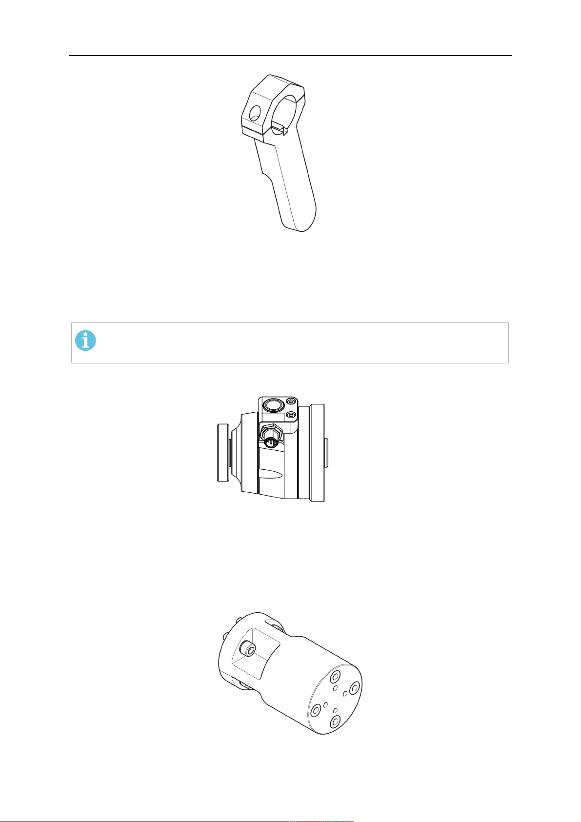
4.3.2.1 Úchyt hořákuRT KSC-2 G/W sbezpečnostním vypínacím mechanismem
Polo
Popis Funkce
žka
1 Držák hrdla hořáku Rozhraní pro hořák AristoRT
2 KrytRT KSC-2 Sestava skabelem arozhraním hořáku
3 Gumová krytka Ochrana bezpečnostního vypínacího mechanismu
4 Hlavní tělesoRT KSC-2 Umožňuje mechanické vychýlení během kolize
0463 373 101
- 16 -
© ESAB AB 2018

4 TECHNICKÉ ÚDAJE
Polo
Popis Funkce
žka
5 Přírubový adaptér Izolační rozhraní na zápěstí robota (musí se hodit ke
konkrétnímu robotu)
6 Indexový kolík Pro přesné vyrovnání spřírubovým adaptérem
7 Konektor pro ovládací kabel Elektrické připojení pro funkci kolizního signálu
asnímání hubice
8 Mikrospínač Snímač pro detekci kolize
4.3.2.2 Pevný úchyt pro hořákRT FLC-2 G/W
Polo
Popis Funkce
žka
1 Držák hrdla hořáku Rozhraní pro hořák AristoRT
2 KrytRT FLC-2 Sestava skabelem arozhraním hořáku
3 Hlavní tělesoRT FLC-2 Umožňuje mechanické vychýlení během kolize
4 Indexový kolík Pro přesné vyrovnání spřírubovým adaptérem
5 Přírubový adaptér Izolační rozhraní na zápěstí robota (musí se hodit
ke konkrétnímu robotu)
6 Konektor pro ovládací kabel
(3pólový)
0463 373 101
Elektrická přípojka pro funkci snímání hubice (pokud
je kdispozici)
- 17 -
© ESAB AB 2018

4 TECHNICKÉ ÚDAJE
4.4 Přírubové adaptéry
Přírubový adaptér potřebný pro instalaci na rameno robota zvolte vzávislosti na typu robota.
Kdispozici jsou přírubové adaptéry pro všechny vhodné standardní systémy asystémy
sdutým zápěstím– viz seznam náhradních dílů.
4.5 Kabelové sestavy
Na připojení kpodavači drátu má vliv kabelová sestava; dostupné verze závisí převážně na
konstrukci systému achladicím médiu (plyn nebo voda)– viz seznam náhradních dílů.
Jmenovité hodnoty platí pro kabely vdélce 1 až 5 m.
Délka kabelové
Infiniturn Helix
sestavy
Jmenovitý výkon
(10minutový cyklus)
Chlazení plynem
(smíšený plyn)
Jmenovitý výkon
(10minutový cyklus)
Max. 500A/ 60%
pracovního cyklu
Max. 350A/ 100%
pracovního cyklu
Max. 600A/ 100%
pracovního cyklu
Max. 400A/ 60%
pracovního cyklu
Max. 320 A/ 100%
pracovního cyklu
Max. 550A/ 100%
pracovního cyklu
Chlazený vodou
Rozsah otáčení Omezená
kompatibilita
Hmotnost
Chlazený plynem
Hmotnost
Chlazený vodou
Délka 1,2m:
2,35 kg
Délka 1,2m:
2,35 kg
Nekonečné možnosti
otáčení
Délka 1,0m:
2,0 kg
Délka 1,0m:
2,0 kg
4.5.1 Kabelové sestavy pro standardní systémRT
Max. 400A/ 60%
pracovního cyklu
Max. 320 A/ 100%
pracovního cyklu
Max. 550A/ 100%
pracovního cyklu
± 270° zneutrální
polohy
Délka 1,0m:
2,0 kg
Délka 1,0m:
2,0 kg
0463 373 101
- 18 -
© ESAB AB 2018

4 TECHNICKÉ ÚDAJE
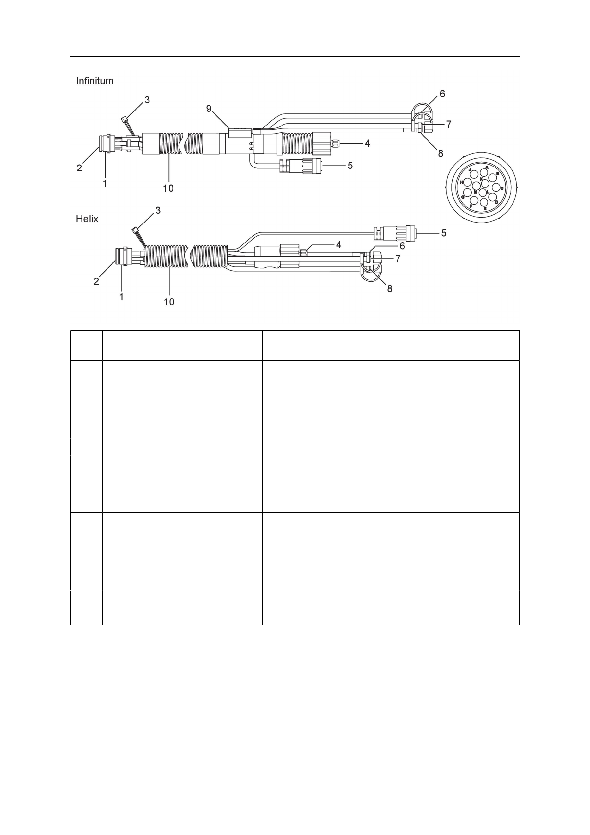
Kolíky konektoru Burndy
A.Dotykové snímání plynové
hubice
C.Snímač kolize
F.0V
G. +napětí motoru
H. –napětí motoru
D.Snímač kolize
E.Zavedení
Polo
Popis Funkce
žka
1 Opěrná příruba hrdla Rozhraní hořáku
2 Ochranný kryt Chrání kabelovou sestavu před poškozením
3 Konektor Burndy, 12pólový Elektrické připojení mezi bezpečnostním vypnutím
apodavačem drátu
4 Řídicí kabel Pro KS-2 (bezpečnostní vypnutí atlačítko)
5 Konektor EURO Připojení podavače drátu
6 Profukovací hadice (černá
krytka)
7 Přívod vody (modrý kryt)
8 Ventil pro zpětný tok vody
Pro čištění hořáku stlačeným vzduchem po cyklu
čištění
Přívod vody pro chlazení hořáku
Zpětný tok ohřáté vody zhořáku
1)
1)
(červený kryt)
9 Zástrčka ovládacího kabelu pro
bezpečnostní vypínací
Elektrické připojení kRT KS-2 pro signál
bezpečnostního vypnutí afunkci snímání hubice
mechanismus
1)
Pouze vodou chlazené systémy hořáku
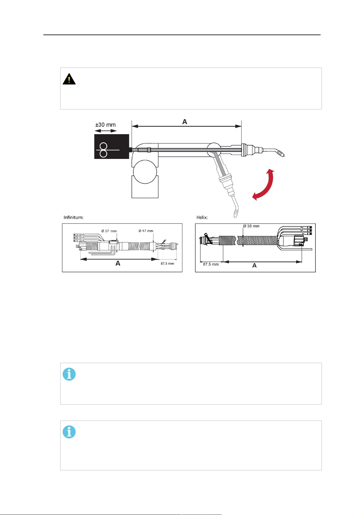
4.5.2 Kabelové sestavy pro systémy sdutým zápěstím
Kabelová sestava Infiniturn umožňuje nekonečné otáčení hořáku vobou směrech. Současně
se přenáší chladicí kapalina, ochranná atmosféra, profukovací vzduch, svařovací výkon
asignál bezpečnostního vypínacího mechanismu.
Kabelová sestava Helix je určena pro otáčení vrozsahu ±270° zneutrální polohy. Lze ji
použít pro ty úlohy svařování, které nevyžadují nekonečné otáčení.
Kabelové sestavy Infiniturn jsou kdispozici ve verzích schlazením plynem avodou.
Kabelové sestavy Helix lze univerzálně použít pro aplikace chlazené plynem nebo vodou.
POZOR!
Nepřipojujte kabelovou sestavu kabelů Helix provozovanou splynovým hrdlem
hořáku ksystému vodního chlazení.
0463 373 101
- 19 -
© ESAB AB 2018
4 TECHNICKÉ ÚDAJE
Polo
Popis Funkce
žka
1 Příruba Rozhraní úchytu hořákuRT KSC-2 /RT FLC-2
2 Indexový kolík Zajišťuje správnou orientaci spojky
3 Zástrčka ovládacího kabelu Elektrické připojení kRTKSC-2 pro signál
bezpečnostního vypnutí afunkci snímání hubice
(je-li kdispozici)
4 Konektor EURO Připojení podavače drátu
5 Řídicí kabel Elektrické připojení pro signál bezpečnostního
vypnutí (zRT KSC-2) afunkci snímání hubice
(snímání hubice je ve standardní výbavě systému
Helix, nikoli systému Infiniturn)
6 Ventil pro zpětný tok vody
Zpětný tok ohřáté vody zhořáku
(červený kryt)
7 Přívod vody (modrý kryt) Přívod vody pro chlazení hořáku
8 Profukovací hadice (černá
Pro čištění hořáku stlačeným vzduchem po svaření
krytka)
9 Připojení médií Nekonečně otočné připojení spřenosem médií
10 Ochranný kryt Chrání kabelovou sestavu před poškozením
0463 373 101
- 20 -
© ESAB AB 2018
5 INSTALLATION
5 INSTALLATION
VAROVÁNÍ!
For your own safety, make sure that the robot is either in standby or power-less
state before doing maintenance work in the moving radius of the robot.
Follow the assembly instructions exactly. Pay attention during assembly that the cables are
not damaged. Damaged cables can lead to a short circuit, which may damage the electronics
of the robot or the welding torch.
Use only original ESAB components that have been specially developed for this purpose.
Only then the correct functioning of the whole welding torch system can be guaranteed.
5.1 RTKS-2 standard arm installation
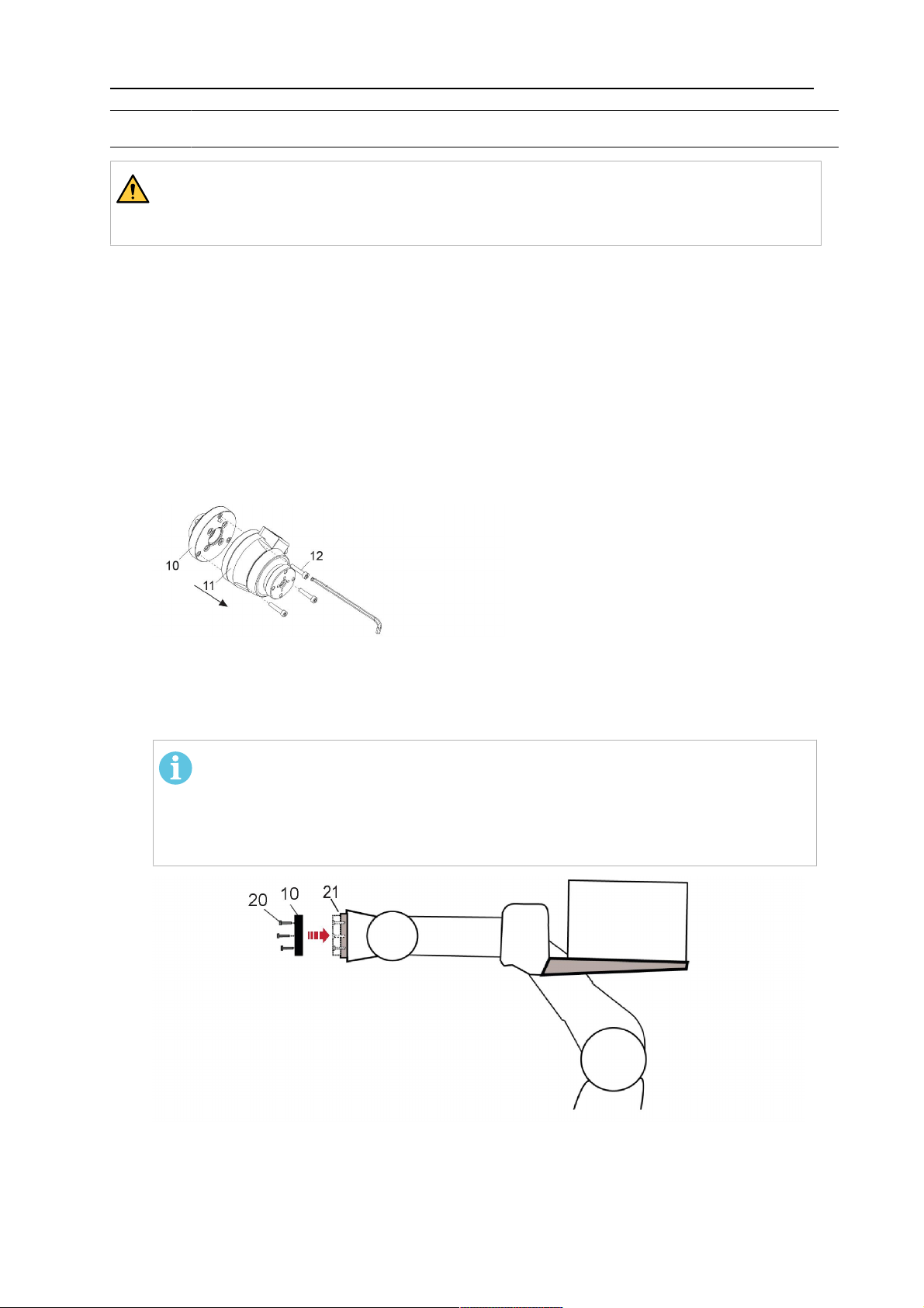
5.1.1 RTKS-2 safety-off mechanism
1. Dismount the insulation flange (10) from the RTKS-2 (11) by removing the screws
(12).
2. Position the insulation flange (10) with the index pin on the robot arm and fix it with the
screws (20) included.
The insulation flange (10) is directly compatible with robots with tool flange according
to DIN ISO 9409-1-A40 (diameter 40mm, 4×M6). If the insulation flange (10) does
not fit, use an adapter flange (21).
POZOR!
Ensure that the index pin is located correctly. The maximum torque of 1.2Nm
(10.5in.lb) must be observed for the fastening of the adapter flange screws.
Prevent self-loosening of the screws by using suitable thread locking
measures.
3. Mount the RTKS-2 the back on the insulation flange (10).
0463 373 101
- 21 -
© ESAB AB 2018
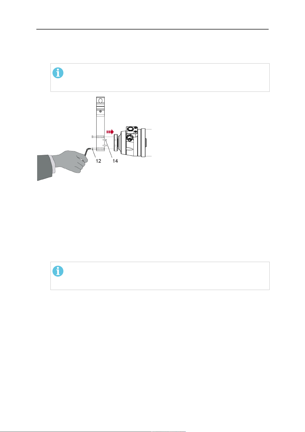
5 INSTALLATION
4. Position the mount on the RTKS-2 and carefully insert the cylindrical pins (14) into the
holes provided. Take the position of the torch into account. Two mounting positions
may be potentially possible.
5. Screw the mount evenly using the enclosed cylinder screws with hexagon socket (12).
POZOR!
The maximum tightening torque for the cylinder screw (5) is 6Nm (53in.lb)
and the property class category is 8.8.
12 - Cylinder screw with hexagon socket
M6DIN912 (length of the screw depending
on the torch mount)
14 - Cylindrical pins Ø4×20
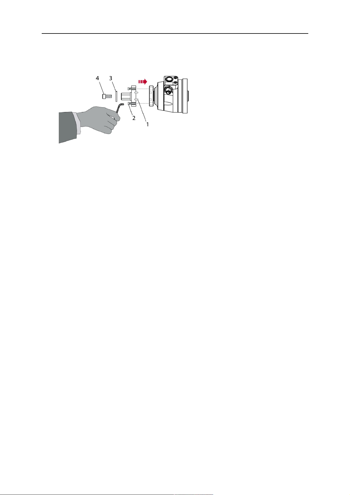
5.1.1.1 Torch installation with adjustable mount
Torch mounts with a central clamping assembly can only be fastened on the journal of the
mounting flange. For this, the mounting flange must be fastened first.
1. If applicable, carefully press the cylindrical pins (1) into the corresponding holes in the
mounting flange. The pins should protrude by approximately 5 mm (0.2 in.).
2. Position the mount on the safety-off mechanism RTKS-2 and carefully insert the
cylindrical pins (1) into the holes provided. In doing so, take the later position of the
torch into account. Two mounting positions may be potentially possible.
3. Then screw down the mounting flange evenly using the enclosed cylinder screws with
hexagon socket (2).
POZOR!
The maximum tightening torque for the cylinder screw (2) is 7.1 Nm (62.8
in.lb) and the property class category is 8.8.
0463 373 101
- 22 -
© ESAB AB 2018
5 INSTALLATION
4. Unscrew the axial cylinder screw with hexagon socket (4) out of the mounting flange
together with the washer (3).
1 - Cylindrical pins Ø4×14 3 - Washer Ø9 mm
2 - Cylinder screw with hexagon socket
M6×16
4 - Axial cylinder screw with hexagon
socket M8×16
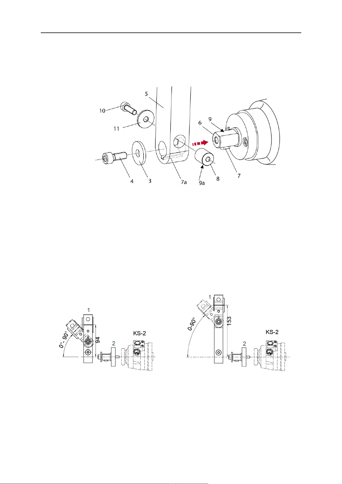
5. Place the torch mount (5) onto the journal (6) of the mounting flange, paying attention
while doing so to the exact alignment of the feather key (7) and the corresponding
groove (7a).
6. Insert the clamping mandrel (8) into the lateral hole (see illustration) and position it so
that the mating surfaces (9a) of the clamping mandrel rest on the mating surface (9) of
the journal.
0463 373 101
- 23 -
© ESAB AB 2018
5 INSTALLATION
7. Fix the clamping mandrel from the opposite side using the M6 cylinder screw with
hexagon socket (10) and the Ø22 mm washer (11).
8. Screw the axial cylinder screw (4) with the Ø9 mm washer (3) into the mounting flange
and tighten firmly.
3 - Washer Ø9 mm 8 - Clamping mandrel
4 - Axial cylinder screw with hexagon
9 - Mating surface of mounting flange
socket M8×16
5 - Torch mount 9a - Mating surfaces of clamping mandrel
6 - Mounting flange journal 10 - Cylinder screw with hexagon socket
M6×30
7 Feather key 11 - Washer Ø22×6.4 mm
7a - Groove for feather key
5.1.2 Standard arm cable assembly for KS-2 and FL-2
The cable assembly must be aligned to the intended use in length and design. The type of
cooling for the torch and the cable assembly must be the same (either gas or water cooled
respectively). In order to prevent damage to the torch system and other components, it is
imperative to observe the following instructions.
0463 373 101
- 24 -
© ESAB AB 2018
5 INSTALLATION
UPOZORNĚNÍ!
• Coordinate the length and design of the cable assembly to suit the range of
action of the robot.
• Do not bend, compress or overstretch the cable assembly.
• Fix the cable assembly such that is can be moved freely and cannot become
entangled.
• Any additional holding devices possibly installed, for example a balancer,
must not crush or bend the cable assembly.
• Extreme turning movements must be avoided in which the cable assembly
may become twisted.
• Chafing on the robot or other objects must be excluded.
1. Unscrew the cylinder screws (1) and lift off the top section (2) of the torch mount.
2. Insert the feather key (4) into the recess of the neck support flange (3) from below.
3. Align the neck support flange (3) including the feather key (4) to the groove (5) of the
torch mount and push into the groove right up to the stop of the flange.
4. Hold the cable assembly in this position and simultaneously place the top section (2)
back onto the torch mount. First screw both cylinder screws (1) loosely in to about the
same length, then tighten alternately. The top section (2) of the mount should have an
even gap to the bottom section.
The front part of the cable assembly is directly clamped into the torch mount (see
illustration below).
1 - Cylinder screws 4 - Feather key
2 - Torch mount top section 5 - Groove for feather key
3 - Neck support flange
5.1.3 RTKS-2 wire feeder connection
In order to be able to create the connection, the cable assembly must be mounted as
described in the "Installing the cable assembly" section and equipped following "Installing the
wire guide" section. Only then can the central and media connection take place. Proceed as
described below:
0463 373 101
- 25 -
© ESAB AB 2018

5 INSTALLATION
1. Connect the central connector of the cable assembly (2) to the wire feeder cabinet
socket. Tighten the central connector sleeve nut fingertight. Do not use tools.
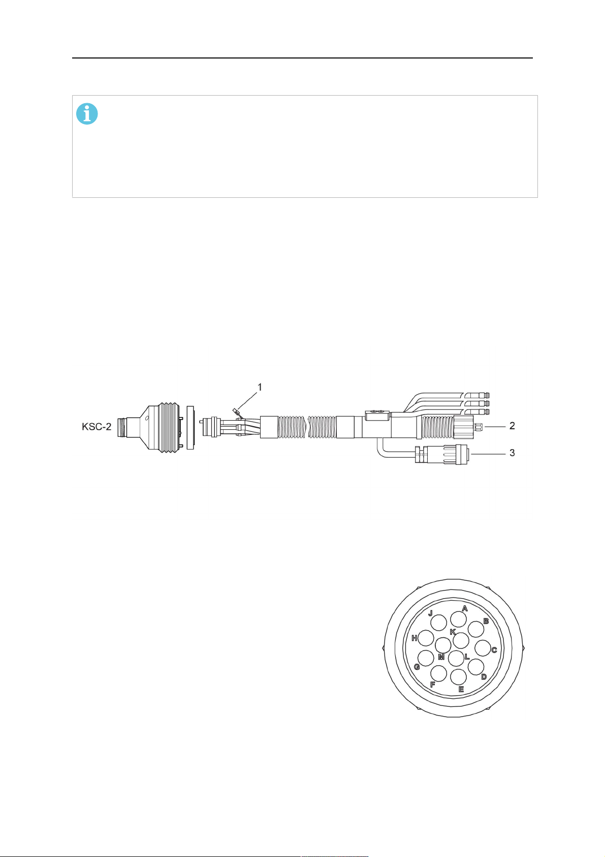
1 - Burndy Connector 4 - Return of heated water (red cap)
2 - EURO central connector 5 - Return of heated water (red cap)
3 - Air blow-out 6 - Main Wire feeder
2. For water cooled systems. Connect the water hoses to the cooling circuit. The end of
the hose marked blue (4) is connected to the water outlet, and the end marked red (5)
is connected to the water return.
3. Connect the blow-out line (3) to the corresponding connection of the feeder.
4. Connect the Burndy Connector to the wire feeder. (1) to the feeder. See section
"Electrical connections".
POZOR!
All hoses and the control line must be installed so they can not bend or get
damaged!
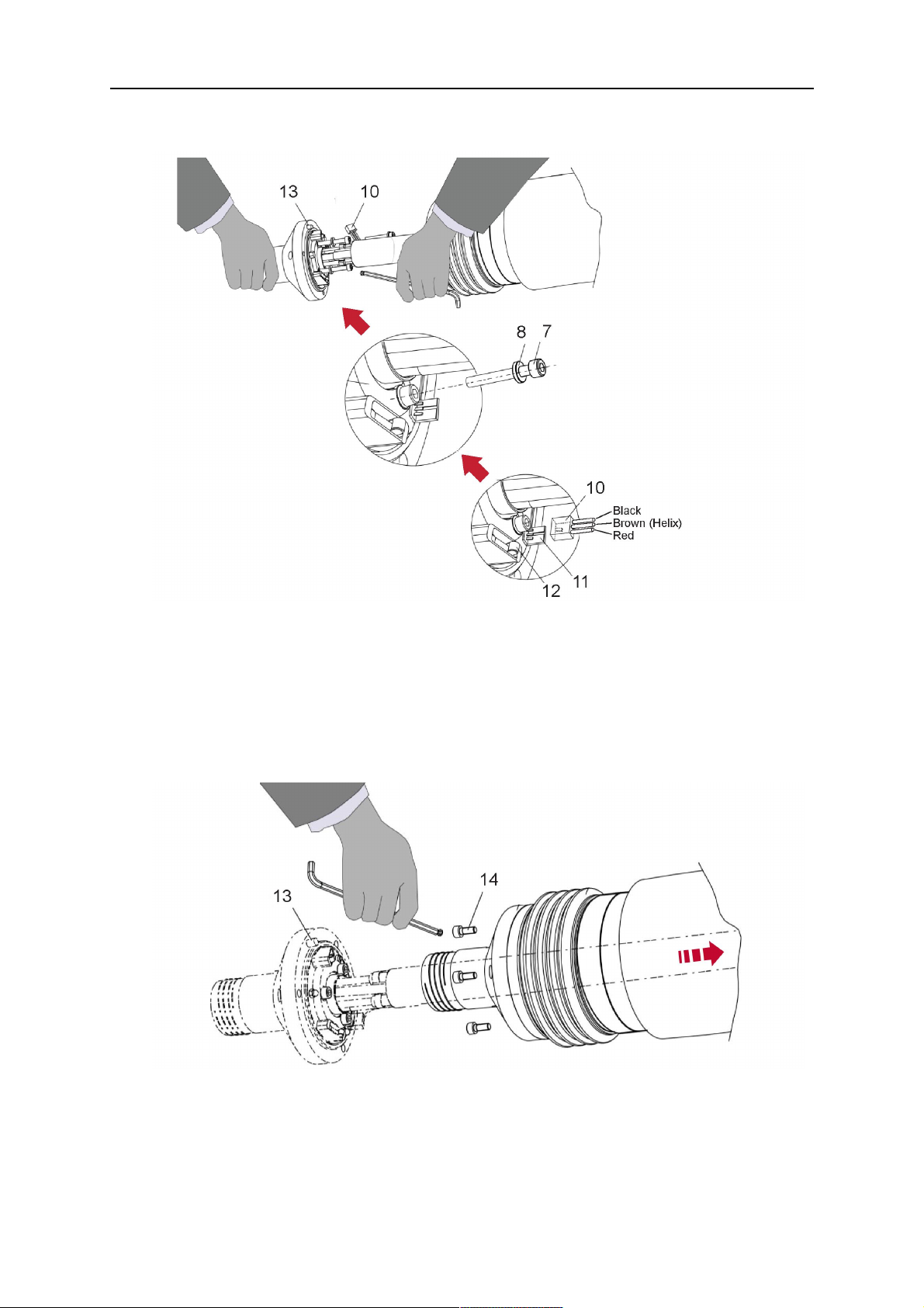
5.1.4 RTKS-2 electrical connections
5.1.4.1 RTKS-2 safety-off mechanism connection
The switch for the safety-off functionality RTKS-2 is connected through the control cable,
see (3) in the illustration below. This connects to the RTKS-2 unit via the 4-pole plug (4) that
contains circuits for the push-button (6) and the safety-off signal (7).
If a collision is detected, the control circuit for the safety-off signal (7), which is normally
closed, will be interrupted.
Rating of the control circuit: max. 48 V / 1 A
0463 373 101
- 26 -
© ESAB AB 2018

5 INSTALLATION
2 - Burndy connector 5 - RTKS-2 connector for control cable plug
4 - Control cable plug
Kolíky konektoru Burndy
A.Dotykové snímání plynové
hubice
C.Snímač kolize
F.0V
G. +napětí motoru
H. –napětí motoru
D.Snímač kolize
E.Zavedení
If the robot control provides a control circuit for nozzle sense functionality, the connection is
accomplished with a 1-wire connection.
Rating of the control circuit: max 50 V / 5 A.
NEBEZPEČÍ!
If the nozzle sense function is not being used, the open end of the control cable on
the power source connection side must be properly isolated in order to avoid short
circuits. During certain problems on the torch head, the full welding potential may be
present on this cable.
UPOZORNĚNÍ!
After detection of contact (gas nozzle on work piece), quickly reduce or cut off the
maximum current in the nozzle sense circuit in order to avoid overloading of the
system.
Allowed load max. 1 minute at the rated nominal current.
5.1.5 RTKS-2 Torch installation
Continue according to section "Torch installation".
0463 373 101
- 27 -
© ESAB AB 2018

5 INSTALLATION
5.2 RTFL-2 standard arm installation
5.2.1 RTFL-2 rigid mount
1. Position the RT FL-2 (2) with the index pin on the robot arm and fix it with the hexagon
socket screw included.
The FL-2 is directly compatible with robots with tool flange according to DIN ISO
9409-1-A40 (diameter 40mm, 4×M6). If the rigid mount does not fit, use an adapter
flange (3).
POZOR!
Ensure that the index pin is located correctly. The maximum torque of 1.2Nm
(10.5in.lb) must be observed for the fastening of the adapter flange screws.
Prevent self-loosening of the screws by using suitable thread locking
measures.
2. Install torch mount (1). Only torch mounts having a hole pattern equivalent with the
mounting surface may be attached. If necessary, carefully press the cylindrical pins (4)
into the corresponding holes in the bracket. The pins should protrude by
approximately 5mm (0.2in.). Position the torch mount on the RTFL-2 (2) and
carefully insert the cylindrical pins (4) into the holes provided. Take the position of the
torch into account. Two mounting positions may be potentially possible.
3. Screw the mount evenly using the enclosed cylinder screws with hexagon socket (5).
POZOR!
The maximum tightening torque for the cylinder screw (5) is 6Nm (53in.lb)
and the property class category is 8.8.
0463 373 101
- 28 -
© ESAB AB 2018

5 INSTALLATION
4 - Cylindrical pins Ø4×20
5 - Cylinder screw with hexagon socket M6
DIN 912 (length of the screw depending on
the torch mount)
Side view
Torch installation with adjustable mount
Torch mounts with a central clamping assembly can only be fastened on the journal of the
mounting flange. For this, the mounting flange must be fastened first.
1. If applicable, carefully press the cylindrical pins (1) into the corresponding holes in the
mounting flange. Avoid the formation of burrs. The pins should protrude by
approximately 5 mm (0.2 in.).
2. Position the mount on the RTFL-2 and carefully insert the cylindrical pins (1) into the
holes provided. In doing so, take the later position of the torch into account. Two
mounting positions may be potentially possible.
3. Then screw down the mounting flange evenly using the enclosed cylinder screws with
hexagon socket (2).
POZOR!
The maximum tightening torque for the cylinder screw (2) is 7.1 Nm (62.8
in.lb) and the property class category is 8.8.
4. Unscrew the axial cylinder screw with hexagon socket (4) out of the mounting flange
together with the washer (3).
1 - Cylindrical pins Ø4×14 3 - Washer Ø9 mm
2 - Cylinder screw with hexagon socket
M6×16
4 - Axial cylinder screw with hexagon
socket M8×16
5. Place the torch mount (5) onto the journal (6) of the mounting flange, paying attention
while doing so to the exact alignment of the feather key (7) and the corresponding
groove (7a).
0463 373 101
- 29 -
© ESAB AB 2018

5 INSTALLATION
6. Insert the clamping mandrel (8) into the lateral hole (see illustration) and position it so
that the mating surfaces (9a) of the clamping mandrel rest on the mating surface (9) of
the journal.
7. Fix the clamping mandrel from the opposite side using the M6 cylinder screw with
hexagon socket (10) and the Ø22 mm washer (11).
8. Screw the axial cylinder screw (4) with the Ø9 mm washer (3) into the mounting flange
and tighten firmly.
3 - Washer Ø9 mm 8 - Clamping mandrel
4 - Axial cylinder screw with hexagon
9 - Mating surface of mounting flange
socket M8×16
5 - Torch mount 9a - Mating surfaces of clamping mandrel
6 - Mounting flange journal 10 - Cylinder screw with hexagon socket
M6×30
7 - Feather key 11 - Washer Ø22×6.4 mm
7a - Groove for feather key
5.2.2 RTFL-2 torch installation
Continue according to section "Torch installation".
5.3 RTKSC-2 hollow wrist system installation
5.3.1 RTKSC-2 mount with safety off mechanism
UPOZORNĚNÍ!
For hollow wrist systems make sure that the clear space around the robot is at least
Ø45 mm (1.8 in.) around the wrist and 50 mm (2.0 in.) near the wire feeder.
0463 373 101
- 30 -
© ESAB AB 2018

5 INSTALLATION
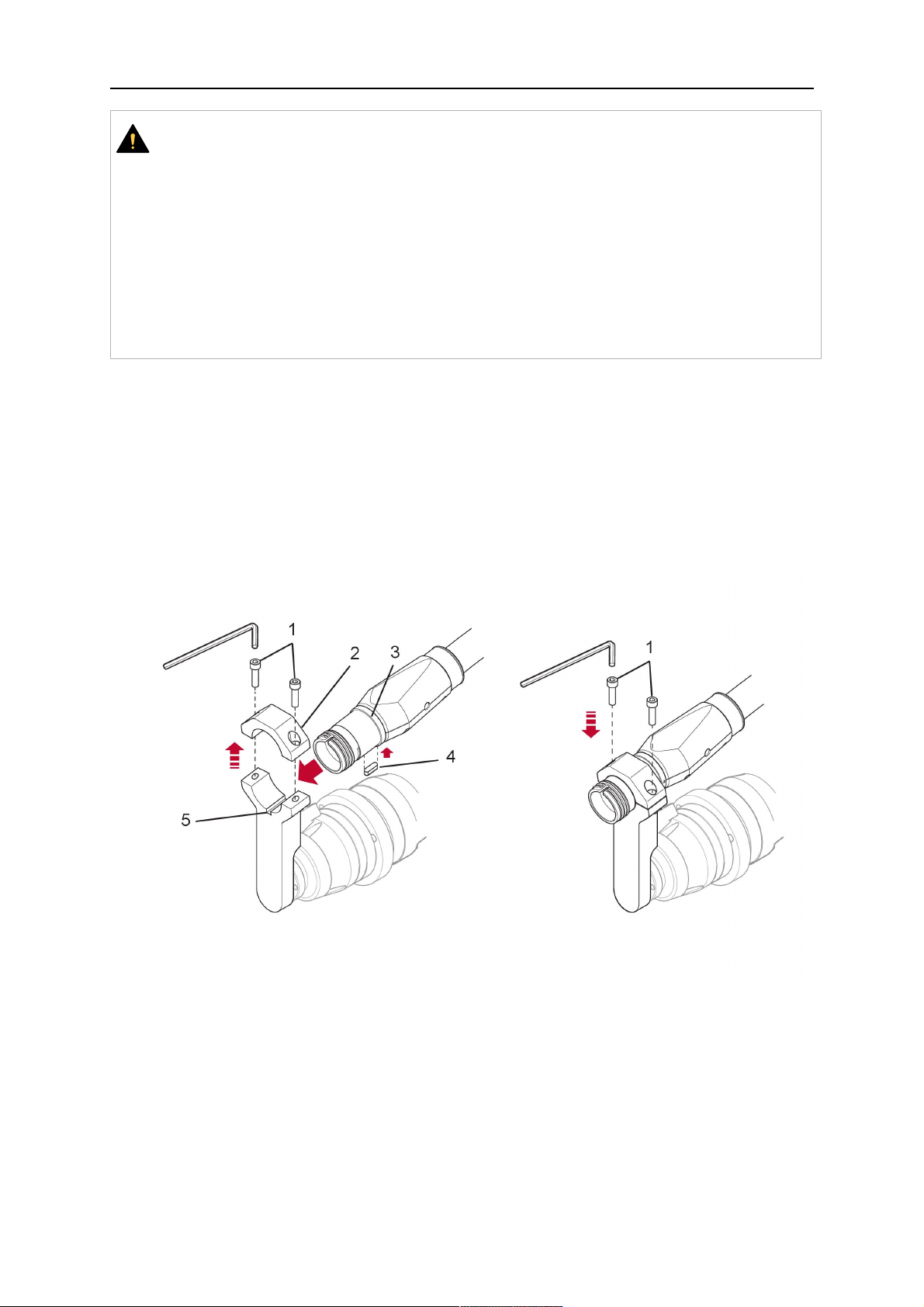
1. Remove the three screws (2) from the front cover (3) of the torch mount and carefully
pull the cover off the RTKSC-2 main body (5). Take care not to damage the micro
switches installed inside the assembly.
1 - Hexagon wrench 4 mm 4 - Rubber boot
2 - 3× M5×12 screws 5 - RT KSC-2 main body
3 - RT KSC-2 front cover
1. Pull off the rubber boot (4) from the RTKSC-2 main body (5) to the front.
2. Now position the RTKSC-2 main body (5) on the adapter flange (7) so that the index
pin is correctly seated. Attach with the screws (6) enclosed.
3. Reinstall the rubber boot (4) on the RTKSC-2 main body (5) and make sure it is
correctly located in the grooves on the front and back flange.
4. Istall the adapter flange (7) on the robot.
Fastening torque max. 2.2 Nm (19.5 in.lb).
1 - Hexagon wrench 4 mm 3 - 3× M5×12 hexagon socket screws
2 - Rubber boot 4 - Adapter flange
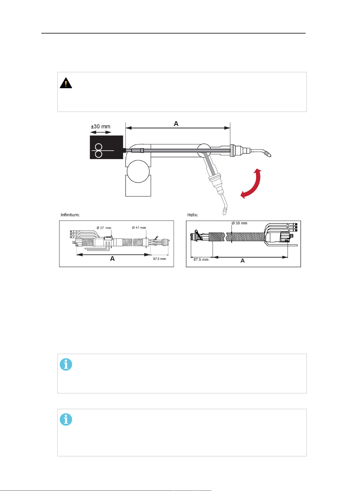
5.3.2 Mounting the cable assembly
POZOR!
In order to adjust the wire feeder position to the cable assembly length, it must be
mounted on an adjustable support with a possible movement of ±2-3cm (±1in.) to
the back and to the front. The length of the cable assembly must be determined
from the centred mounting position of the wire feeder.
1. Move the robot arm into a completely straight position, see illustration below. Make
sure that (1) axis 6 (rotation around the torch axis) is in 0° position.
2. Move the feeder (3) completely to the back in order to create space for inserting the
cable assembly. If it is not possible to move the feeder sufficiently, it should be
removed from the robot.
0463 373 101
- 31 -
© ESAB AB 2018
5 INSTALLATION
3. Insert the cable assembly with the coupling (2) first into the robot arm and feed it
through the robot wrist.
4. The feeder should only be installed again after the correct mounting position with
respect to the cable length has been determined. (See section "Installing the cable
assembly").
UPOZORNĚNÍ!
Axis 6 must be in 0° position.
5.3.2.1 RTKSC-2 feeder cabinet connections
When installed for the first time, the position of the wire feeder cabinet must be adjusted to
the length of the cable assembly. First, the robot arm must be fully extended (straight).
UPOZORNĚNÍ!
As long as the correct position of the feeder corresponding to the length of the cable
assembly has not been determined, be careful when moving the robot arm and
avoid overstretching the cable. It is helpful to loosen the positioning screws of the
feeder before moving the robot arm to allow the feeder to follow the cable assembly.
0463 373 101
- 32 -
© ESAB AB 2018
5 INSTALLATION
1. Loosen the sliding mechanism of the wire feeder and connect the cable assembly.
2. Now adjust the position of the wire feeder to suit the length of the Infiniturn or Helix
cable, as indicated with "A" in the illustration below.
UPOZORNĚNÍ!
When adjusting the position of the feeder cabinet, make sure that the cable
assembly is not under stress when the robot arm is in stretched-out position.
It is normal for the cable assembly to sag slightly, it should never be taut.
3. Before securing the wire feeder in its permanent position, ensure that the Euro
connectors are tightly connected. Then turn the torch mount down and up again
(rotating on the axis 5), in order not to tighten the cable assembly too much against
the feeder (see illustration above). Once this is done, tighten the feeder in that
position.
4. For water cooled systems, connect the water lines to the cooling circuit. See section
"Cable assemblies for hollow wrist systems" in the TECHNICAL DATA chapter for
indications.
The hose with the blue rubber cap is for cooling water to the torch, the hose with the
red rubber cap returns the heated water. Make sure the hoses will not kink or get
otherwise blocked.
POZOR!
A Helix cable assembly used for a gas cooled system must not be connected
to a cooling circuit. As the water connections are not needed, they may be cut
off.
5. Connect the blow-out hose (black rubber cap) to the corresponding outlet of the wire
feeder.
POZOR!
If the blow-out function is not used, the blow-out hose must be sealed with the
rubber cap enclosed. With Infiniturn systems, the blow-out air must be
supplied to the corresponding connection hose, if it is not permitted to connect
blow-out air to the shield gas connection!
6. Install the necessary plug on the control cable and connect it to the safety off circuit
interface of the wire feeder (see section "Electrical connections").
0463 373 101
- 33 -
© ESAB AB 2018
5 INSTALLATION
5.3.3 RTKSC-2 cable assembly
The cable assembly must be aligned to the intended use in length and design. The type of
cooling for the torch and the cable assembly must be the same (either gas or water cooled
respectively). In order to prevent damage to the torch system and other components, it is
imperative to observe the following instructions.
UPOZORNĚNÍ!
• Coordinate the length and design of the cable assembly to suit the range of
action of the robot.
• Do not bend, compress or overstretch the cable assembly.
• Fix the cable assembly such that is can be moved freely and cannot become
entangled.
• Any additional holding devices possibly installed, for example a balancer,
must not crush or bend the cable assembly.
• Extreme turning movements must be avoided in which the cable assembly
may become twisted.
• Chafing on the robot or other objects must be excluded.
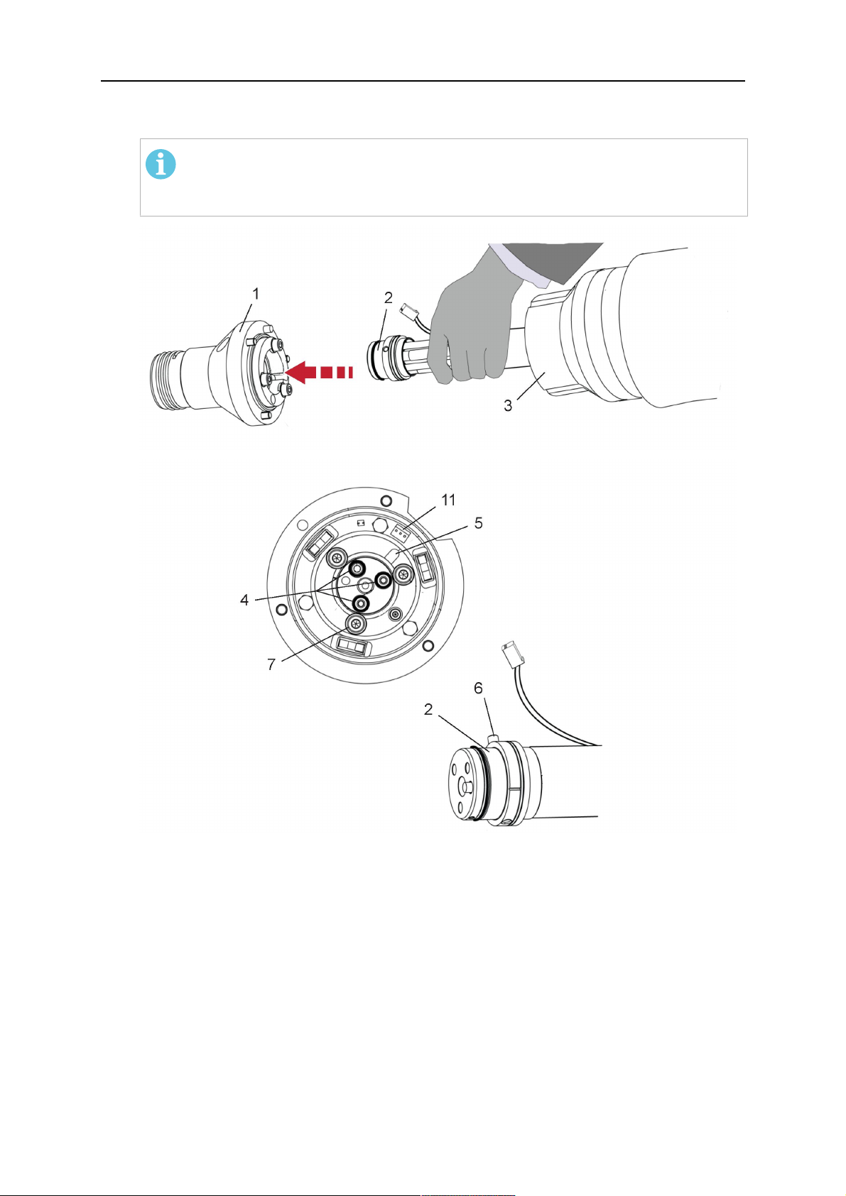
5.3.3.1 RTKSC-2 cable assembly installation
POZOR!
For some robots, it may be possible to deviate from this order, and first connect the
cable assembly to the RTKSC-2, then thread the cable from the front through the
robot arm. If in doubt, follow the suggested order.
1. Loosen the three screws (7) with the associated washers and remove them from the
RTKSC-2 cover (1). See illustration below.
2. Install the supplied O-rings (4) into the grooves in the cover (1).
3. Pull the cable assembly approximately 15 cm (6 in.) from the main body (3).
0463 373 101
- 34 -
© ESAB AB 2018
5 INSTALLATION
4. Insert the coupling (2) into the socket of the cover (1) as shown. Align the index pin (6)
with the index hole (5) in the main body and insert completely.
POZOR!
Make sure that the position of the O-rings are not shifted by the index pin
during the assembly.
1 - RTKSC-2 cover 5 - Index hole
2 - Coupling 6 - Index pin
3 - RTKSC-2 main body 7 - 3× M5×35 screws
4 - 3× O-ring for water cooled systems 11 - Control cable connector
5. Insert the three screws (7) with the associated washers (8) and tighten gently with the
enclosed hexagonal wrench, see below illustration.
Fastening torque approximately 2 Nm (18 in.lb).
0463 373 101
- 35 -
© ESAB AB 2018
5 INSTALLATION
6. If present, insert the control cable plug (10) into the connector (11) and make sure it is
firmly seated.
7 - 3× M5×35 screw 11 - Control cable connector
8 - Washer 12 - 2× Micro switch
10 - Control cable plug 13 - Index pin
7. Gently push back the cable assembly into the robot arm and carefully seat the
RTKSC-2 cover (1) in place. Observe the index pin (13) to be in the correct position.
Make sure the two micro switches (12) are not damaged if present.
8. Insert the three M5 screws (14) and tighten without excessive force.
13. Index pin
14. 3× M5×12 screws
0463 373 101
- 36 -
© ESAB AB 2018
5 INSTALLATION
5.3.3.2 RTKSC-2 electrical connections
POZOR!
After connecting the control cable, secure the cable in order to protect it from getting
caught while the robot is moving.
Usually, the control cable will be directly connected to the wire feeder. See the
manufacturer's documentation for details. The link to the robot control is then
implemented via the power source controller.
RTKSC-2 safety-off mechanism connection
The switch for the safety-off functionality RTKSC-2 is connected through the control cable,
see (3) in the illustration below. This connects to the RTKSC-2 unit via the control cable plug
(1).
The safety-off signal requires a 2-wire connection (black/black) to the safety-off circuit in the
robot control (5).
If a collision is detected, the control circuit (normally closed) will be interrupted (4).
Rating of the control circuit: max. 48 V / 1 A.
1 - Control cable plug 3 - Burndy connector VVV
2 - EURO central connector
Kolíky konektoru Burndy
A.Dotykové snímání plynové
hubice
C.Snímač kolize
F.0V
G. +napětí motoru
H. –napětí motoru
D.Snímač kolize
E.Zavedení
RTKSC-2 nozzle sense function connection
If the robot control provides a control circuit for nozzle sense functionality.
The connection is accomplished with a 2-wire connection (black/black) to the nozzle sense
circuit in the robot control (5), see illustration below.
0463 373 101
- 37 -
© ESAB AB 2018
5 INSTALLATION
Usually, the control cable will be directly connected to the wire feeder. See the
manufacturer's documentation for details. The link to the robot control is then implemented
via the power source robot interface.
Rating of the control circuit: max. 50 V / 5 A.
NEBEZPEČÍ!
If the nozzle sense function is not being used, the open end of the control cable on
the power source connection side must be properly isolated in order to avoid short
circuits. During certain problems on the torch head, the full welding potential may be
present on this cable.
UPOZORNĚNÍ!
After detection of contact (gas nozzle on work piece), quickly reduce or cut off the
maximum current in the nozzle sense circuit in order to avoid overloading of the
system.
Allowed load max. 1 minute at the rated nominal current.
1 - Control cable plug 3 - Control cable
2 - EURO central connector
5.3.4 RTKSC-2 torch installation
Continue according to section "Torch installation".
0463 373 101
- 38 -
© ESAB AB 2018
5 INSTALLATION
5.4 RTFLC-2 installation
5.4.1 RTFLC-2 mount
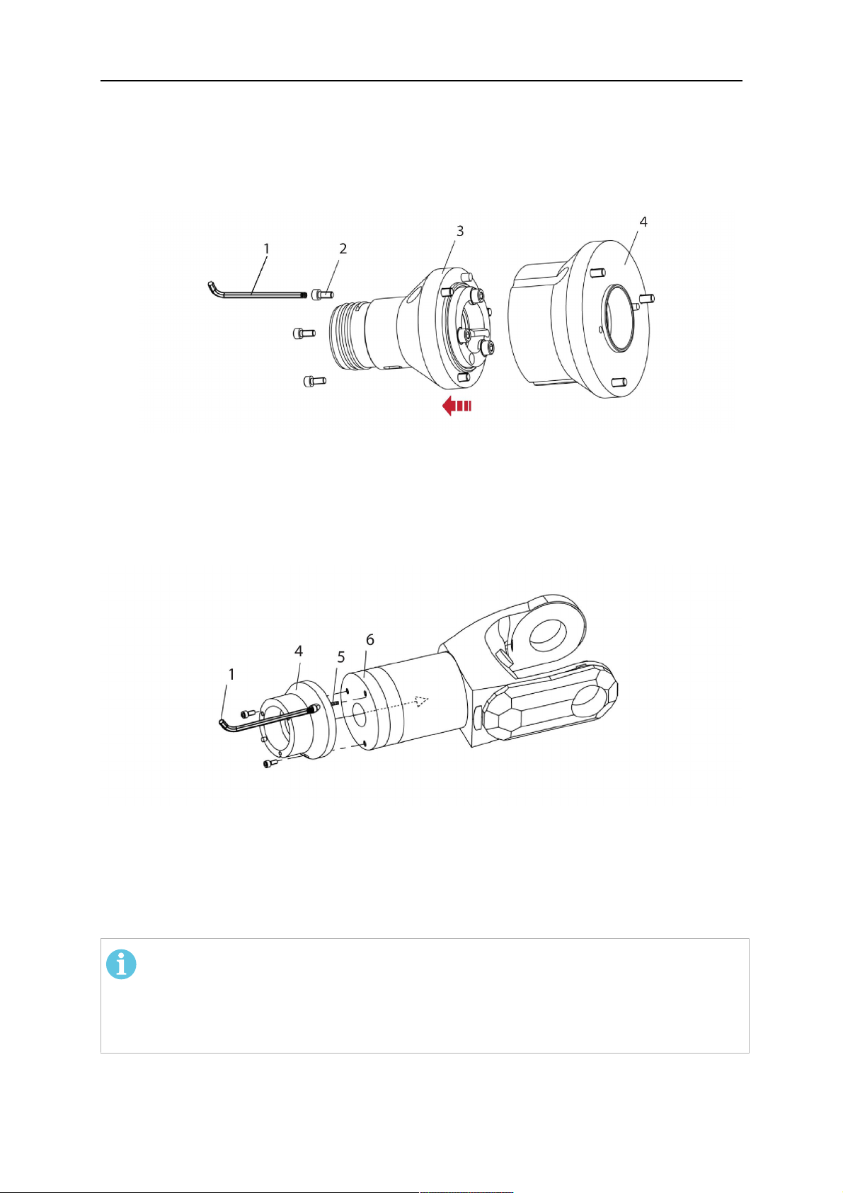
1. Remove the three M5 screws (2) from the front cover (3) of the RT FLC-2 torch mount
and carefully pull the cover off the main body (4).
1 - Hexagon wrench 4 mm 3 - RT FLC-2 front cover
2 - 3× M5×12 screws 4 - RT FLC-2 main body
2. Now position the RT FLC-2 main body (4) on the adapter flange (6) so that the index
pin is correctly seated. Attach with the screws (5) enclosed
Fastening torque max. 2.2 Nm (19.5 in.lb).
1 - Hexagon wrench 4 mm 5 - 3× M5×12 hexagon socket screws
4 - RT FLC-2 main body 6 - Adapter flange
5.4.2 RTFLC-2 wire feeder connection
5.4.2.1 Feeding through the robot arm
POZOR!
In order to adjust the wire feeder position to the cable assembly length, it must be
mounted on an adjustable support with a possible movement of ± 2-3 cm (± 1 in.) to
the back and to the front. The length of the cable assembly must be determined
from the centred mounting position of the wire feeder.
0463 373 101
- 39 -
© ESAB AB 2018
5 INSTALLATION
1. Move the robot arm into a completely straight position, see illustration below. Make
sure that (1) axis 6 (rotation around the torch axis) is in 0° position.
2. Move the feeder (3) completely to the back in order to create space for inserting the
cable assembly. If it is not possible to move the feeder sufficiently, it should be
removed from the robot.
3. Insert the cable assembly with the coupling (2) first into the robot arm and feed it
through the robot wrist.
4. The feeder should only be installed again after the correct mounting position with
respect to the cable length has been determined. (See section "Installing the cable
assembly").
UPOZORNĚNÍ!
Important! Axis 6 must be in 0° position.
5.4.2.2 RTFLC-2 feeder cabinet connections
When installed for the first time, the position of the wire feeder cabinet must be adjusted to
the length of the cable assembly. First, the robot arm must be fully extended (straight).
UPOZORNĚNÍ!
As long as the correct position of the feeder corresponding to the length of the cable
assembly has not been determined, be careful when moving the robot arm and
avoid overstretching the cable. It is helpful to loosen the positioning screws of the
feeder before moving the robot arm to allow the feeder to follow the cable assembly.
0463 373 101
- 40 -
© ESAB AB 2018
5 INSTALLATION
1. Loosen the sliding mechanism of the wire feeder and connect the cable assembly.
Refer to the instruction of the feeder manufacturer.
2. Now adjust the position of the wire feeder to suit the length of the Infiniturn or Helix
cable, as indicated with "A" in the illustration below.
UPOZORNĚNÍ!
When adjusting the position of the feeder cabinet, make sure that the cable
assembly is not under stress when the robot arm is in stretched-out position.
It is normal for the cable assembly to sag slightly, it should never be taut.
3. Before securing the wire feeder in its permanent position, ensure that the Euro
connections are tightly connected. Then turn the torch mount down and up again
(rotating on the axis 5), in order not to tighten the cable assembly too much against
the feeder (see illustration above). Once this is done, tighten the feeder in that
position.
4. For water cooled systems, connect the water lines to the cooling circuit. See section
"Cable assemblies for hollow wrist systems" in the TECHNICAL DATA chapter for
indications.
The hose with the blue rubber cap is for cooling water to the torch, the hose with the
red rubber cap returns the heated water. Make sure the hoses will not kink or get
otherwise blocked.
POZOR!
A Helix cable assembly used for a gas cooled system must not be connected
to a cooling circuit. As the water connections are not needed, they may be cut
off.
5. Connect the blow-out hose (black rubber cap) to the corresponding outlet of the wire
feeder.
POZOR!
If the blow-out function is not used, the blow-out hose must be sealed with the
rubber cap enclosed. With Infiniturn systems, the blow-out air must be
supplied to the corresponding connection hose, if it is not permitted to connect
blow-out air to the shield gas connection!
0463 373 101
- 41 -
© ESAB AB 2018

5 INSTALLATION
6. Install the necessary plug on the control cable and connect it to the safety off circuit
interface of the wire feeder (see section "Electrical connections").
5.4.3 RTFLC-2 cable assembly
The cable assembly must be aligned to the intended use in length and design. The type of
cooling for the torch and the cable assembly must be the same (either gas or water cooled
respectively). In order to prevent damage to the torch system and other components, it is
imperative to observe the following instructions.
UPOZORNĚNÍ!
• Coordinate the length and design of the cable assembly to suit the range of
action of the robot.
• Do not bend, compress or overstretch the cable assembly.
• Fix the cable assembly such that is can be moved freely and cannot become
entangled.
• Any additional holding devices possibly installed, for example a balancer,
must not crush or bend the cable assembly.
• Extreme turning movements must be avoided in which the cable assembly
may become twisted.
• Chafing on the robot or other objects must be excluded.
5.4.3.1 RTFLC-2 cable assembly installation
In a hollow wrist system the recommended order of installation is to feed the cable assembly
through the robot arm before connecting the cables to the torch mount.
When the cable assembly is correctly installed in the hollow wrist, continue the installation
according to the procedure described below.
POZOR!
For some robots, it may be possible to deviate from this order, and first connect the
cable assembly to the RTKSC-2 and RTFLC-2, then thread the cable from the front
through the robot arm. If in doubt, follow the suggested order.
1. Loosen the three screws (7) with the associated washers and remove them from the
RTFLC-2 cover (1). See illustration below.
2. Install the supplied O-rings (4) into the grooves in the cover (1). For gas cooled
systems, only one O-ring (4a) is needed, for water cooled systems all three O-rings
are needed.
3. Pull the cable assembly approximately 15 cm (6 in.) from the main body (3).
0463 373 101
- 42 -
© ESAB AB 2018

5 INSTALLATION
4. Insert the coupling (2) into the socket of the cover (1) as shown. Align the index pin (6)
with the index hole (5) in the main body and insert completely.
POZOR!
Take great care that the position of the O-rings is not shifted by the index pin
during the assembly.
1 - RT FLC-2 cover 5 - Index hole
2 - Coupling 6 - Index pin
3 - RT FLC-2 main body 7 - 3× M5×35 screws
4 - 3× O-ring for water cooled systems 11 - Control cable connector
5. Insert the three screws (7) with the associated washers (8) and tighten gently with the
enclosed hexagonal wrench, see below illustration.
Fastening torque approximately 2 Nm (18 in.lb).
0463 373 101
- 43 -
© ESAB AB 2018

5 INSTALLATION
6. If present insert the control cable plug (10) into the connector (11) and make sure it is
firmly seated.
7 - 3× M5×35 screw 11 - Control cable connector
8 - Washer 12 - 2× Micro switch
10 - Control cable plug 13 - Index pin
7. Gently push back the cable assembly into the robot arm and carefully seat the
RTFLC-2 cover (1) in place. Observe the index pin (13) to be in the correct position.
Make sure the two micro switches (12) are not damaged if present.
8. Insert the three M5 screws (14) and tighten without excessive force.
13 - Index pin 14 - 3x M5x12 screws
0463 373 101
- 44 -
© ESAB AB 2018

5 INSTALLATION
5.4.4 RTFLC-2 electrical connections
POZOR!
After connecting the control cable, secure the cable in order to protect it from getting
caught while the robot is moving.
Usually, the control cable will be directly connected to the wire feeder. See the
documentation of the manufacturer for details. The link to the robot control is then
implemented via the power source controller.
5.4.4.1 RTFLC-2 hollow wrist system with Infiniturn cable assembly
Connecting the nozzle sense function
If the robot control provides a control circuit for nozzle sense functionality.
The connection is accomplished with a 2-wire connection (black/black) to the nozzle sense
circuit in the robot control (5), see illustration below.
Usually, the control cable will be directly connected to the wire feeder. See the
manufacturer's documentation for details. The link to the robot control is then implemented
via the power source robot interface.
Rating of the control circuit: max. 50 V / 5 A.
NEBEZPEČÍ!
If the nozzle sense function is not being used, the open end of the control cable on
the power source connection side must be properly isolated in order to avoid short
circuits. During certain problems on the torch head, the full welding potential may be
present on this cable.
UPOZORNĚNÍ!
After detection of contact (gas nozzle on work piece), quickly reduce or cut off the
maximum current in the nozzle sense circuit in order to avoid overloading of the
system.
Allowed load max. 1 minute at the rated nominal current.
1 - Control cable plug 3 - Control cable
2 - EURO central connector
0463 373 101
- 45 -
© ESAB AB 2018

5 INSTALLATION
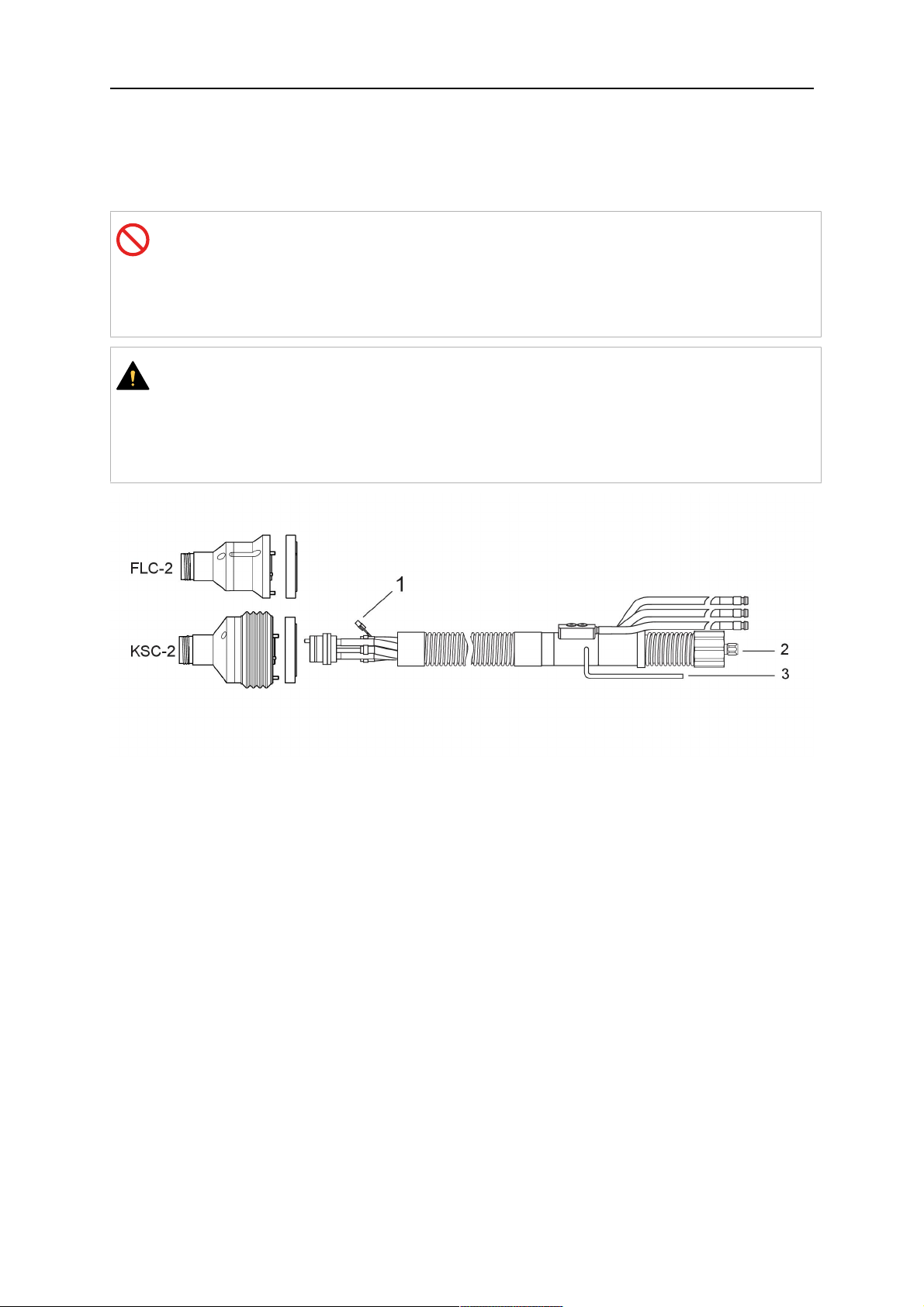
5.4.4.2 RTFLC-2 hollow wrist system with Helix cable assembly
Connecting the nozzle sense function
If the robot control provides a control circuit for nozzle sense functionality.
The connection is accomplished with a 1-wire connection (green) to the nozzle sense circuit
in the robot control (5), see illustration below.
Usually, the control cable will be directly connected to the wire feeder. See the
manufacturer's documentation for details. The link to the robot control is then implemented
via the power source robot interface.
Rating of the control circuit: max. 50 V / 5 A.
NEBEZPEČÍ!
If the nozzle sense function is not being used, the open end of the control cable on
the power source connection side must be properly isolated in order to avoid short
circuits. During certain problems on the torch head, the full welding potential may be
present on this cable.
UPOZORNĚNÍ!
After detection of contact (gas nozzle on work piece), quickly reduce or cut off the
maximum current in the nozzle sense circuit in order to avoid overloading of the
system.
Allowed load max. 1 minute at the rated nominal current.
1 - Control cable plug 3 - EURO central connector
2 - Control cable 4 - Burndy connector
5.5 Torch installation
Be sure to use the correct version of the torch mount and cable assembly (water or gas
cooled).
5.5.1 Torch neck equipment
The torch neck, see (1) in the illustration below, must always be equipped to suit the wire
diameter and material.
0463 373 101
- 46 -
© ESAB AB 2018

5 INSTALLATION
1. Select the correct wire guide, contact tip (4), tip holder (2), gas nozzle (5), and gas
diffuser/spatter protection (3). You will find an exact overview and possible alternative
equipment elements for various torch models in the spare parts list. Only use original
ESAB parts; only then is the fitting accuracy ensured.
2. Firmly tighten the tip holder and the contact tip using a suitable tool for example the
enclosed monkey wrench.
3. When using a split wire guide, remove the installed guide nipple including the o-ring
from the torch flange upon delivery if necessary (see section "Installing the neck
liner").
UPOZORNĚNÍ!
The torch must be completely equipped before welding, especially the gas
diffuser and/or spatter protection and all necessary insulators have to be
installed according to the spare parts list. Welding without these items may
cause immediate destruction of the torch.
1 - Torch neck 4 - Contact tip
2 - Tip holder 5 - Contact tip
3 - Gas diffuser
5.5.2 Aristo RT torch neck installation
POZOR!
Check the O-rings on the flange of the torch neck before mounting. Replace the
O-rings if damaged or lost. Missing or faulty O-rings will lead to leaks of shielding
gas and coolant.
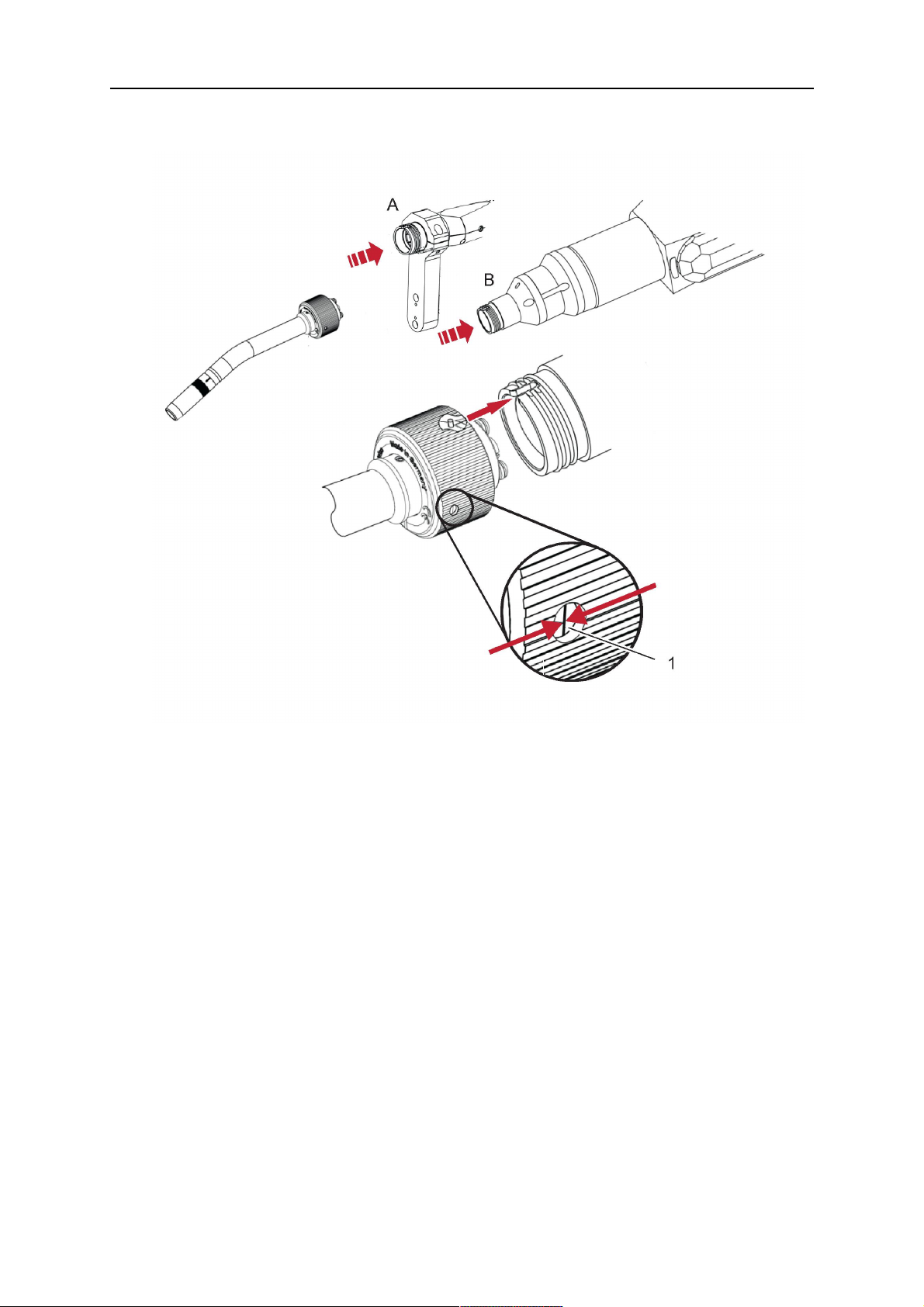
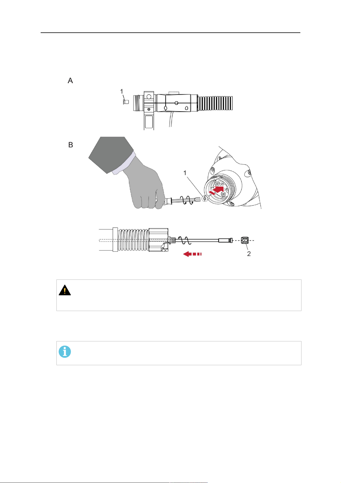
1. For hollow wrist systems, insert the torch into the torch mount in the correct
orientation, so that the locator pin fits into the slot of the RTKSC-2 or RTFLC-2
interface, see (A) in the illustration below. For standard systems, attach the torch to
the RT flange of the cable assembly, (B) in the illustration below.
Installation is only possible in the correct orientation.
2. Tighten the locking nut of the torch neck.
POZOR!
Only tighten by hand, never use tools or excessive force.
0463 373 101
- 47 -
© ESAB AB 2018
5 INSTALLATION
3. The correct seating of the torch can be checked by means of the window (1). If the
torch has been correctly mounted, no gap should be seen through the window (1).
5.6 Installing the wire guide for standard and hollow Wrist arm
Installing the wire guide
Choose the wire guide or liner depending on the filler wire material and diameter to be used,
see the spare parts list. Accurate performance of the system can only be guaranteed when
using original ESAB wire guides.
The recommended wire guide is the split wire guide, which consists of the neck liner and a
separate guide in the cable assembly. The front part of the wire guide, which is most
stressed, can be exchanged easily and independently of the cable assembly wire guide.
For correct installation, the following steps must be followed (example for Euro central
connector).
5.6.1 Installing the neck liner
The neck liner must be selected to fit the material and diameter of the welding wire, see the
spare parts list.
0463 373 101
- 48 -
© ESAB AB 2018
5 INSTALLATION
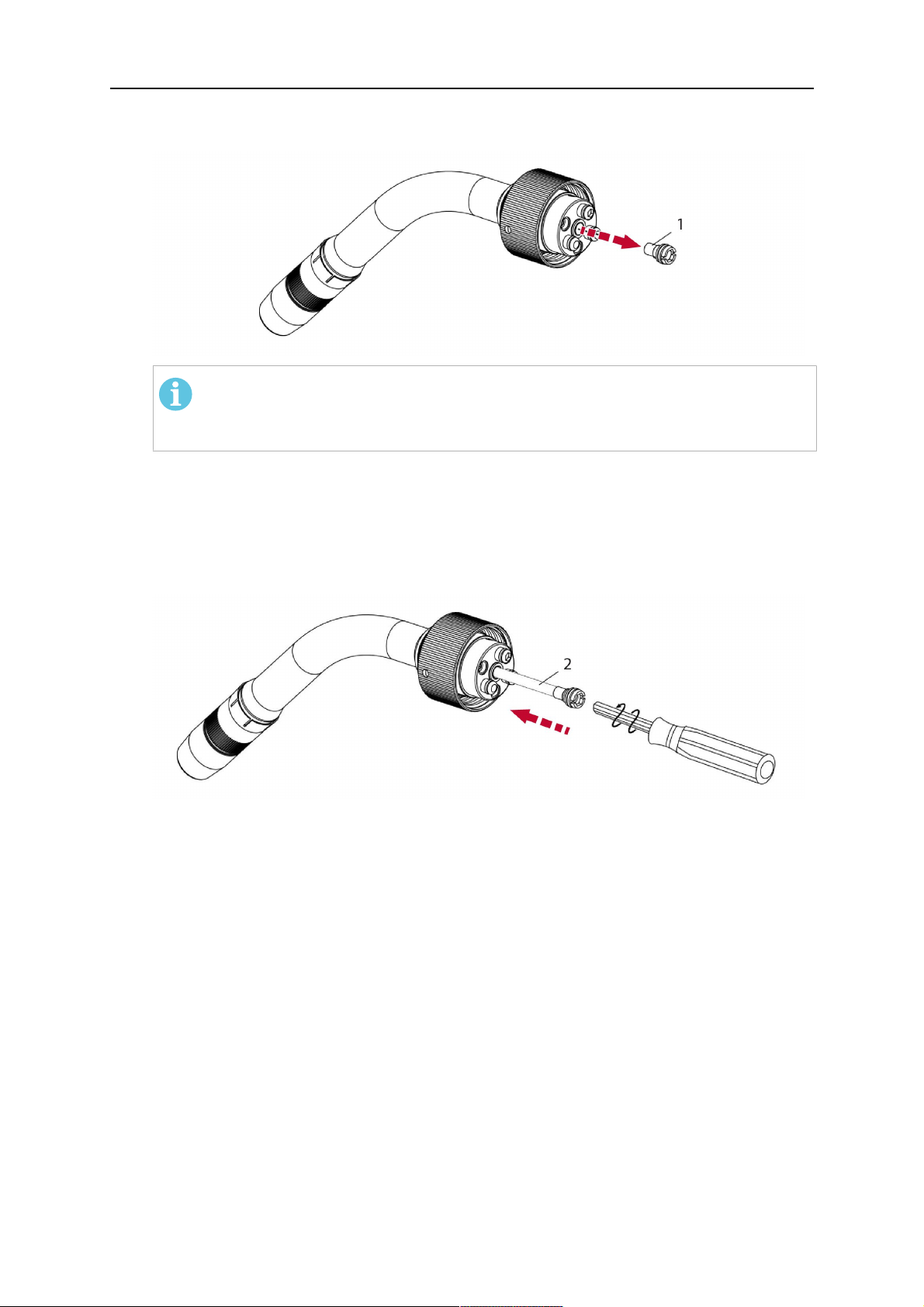
1. If present, remove the central guide nipple (1), from the torch neck using a hexagon
wrench (size 6 mm) or a large flat-blade screwdriver.
POZOR!
The guide nipple (1) can only be used with one-piece liners and must not be
used with the standard RT or hollow wrist system.
2. When replacing the neck liner:
Unfasten the sleeve nut and remove the torch neck.
Unfasten the liner nipple using a hexagon wrench (size 6 mm) and remove nipple and
liner from the torch neck.
3. Remove the gas nozzle and the contact tip.
4. Insert the new neck liner (2) into the torch. Carefully tighten the guide nipple using a
suitable tool, e.g. a hex-wrench (size 6 mm) or a large flat-blade screwdriver.
5. Cut the neck liner flush with the tip holder and remove the neck liner from the torch.
6. Install the contact tip.
7. Insert the neck liner again. It will be stopped by the contact tip. Measure the excess
liner sticking out of the neck.
8. Remove the liner again and shorten the front end by the measured length. Carefully
deburr the edge and make sure that the inner hole is not blocked.
9. Reinstall the neck liner and tighten the guide nipple in the neck.
5.6.2 Installing a split wire guide in the cable assembly
The correct liner must be inserted to suit the filler material and the wire diameter, see the
spare parts list.
The wire guide is inserted through the cable assembly from the rear, reaching the guide
nipple that is installed in the flange where the torch neck will be attached. The following
worksteps must be followed in order to correctly determine the wire guide length. (Example
for Euro central connector).
0463 373 101
- 49 -
© ESAB AB 2018
5 INSTALLATION
1. For standard RT system: Install the guide nipple (1) in the center hole of the neck
support flange, see illustration A below.
For hollow wrist system: Install the guide nipple (1) into the torch interface of the
RTKSC-2 / RTFLC-2 cover, see illustration B below.
2. Remove the sleeve nut (2) from the central connector, and remove the old wire guide.
3. Insert the wire guide through the central connection and push forwards as far as it will
go into the guide nipple (1), applying light pressure.
UPOZORNĚNÍ!
Ensure that the wire guide has advanced right up to the stop at the front,
rotating and pushing forward gently.
4. Measure the excess length that needs to be cut from the wire guide.
5. Remove the wire guide again and shorten the front end by the measured length.
Steel liner: grind down the burred edges if needed.
Plastic liner: make a clean cut and chamfer the edges (e.g. with a pencil sharpener)
POZOR!
Make sure the inner opening of the liner is not obstructed by the cut wire end.
0463 373 101
- 50 -
© ESAB AB 2018
5 INSTALLATION
6. Reinstall the wire guide and attach the sleeve nut (2).
POZOR!
For hollow wrist systems where Infiniturn and Helix cable assemblies are
used, wire guides should be installed without tension so that the ends of the
liners may rotate freely.
Important note when using a plastic liner:
The wire channel between the drive rolls of the feeder and the central
connector of the torch must be fitted with a plastic liner. Depending on the
design of the feeder, a piece of plastic liner inserted into a brass guide tube
can be used.
During wire run-in, make sure that the wire is fed correctly into the plastic liner
of the torch. If necessary, remove the cable assembly from the feeder and
insert the wire, then reattach.
5.6.3 Installing a continuous wire guide in the cable assembly
Installing a steel liner
The wire guide is inserted through the cable assembly from the rear and reaches to the
contact tip. The following worksteps must be followed for the correct calculation of the length
(example for Euro central connector):
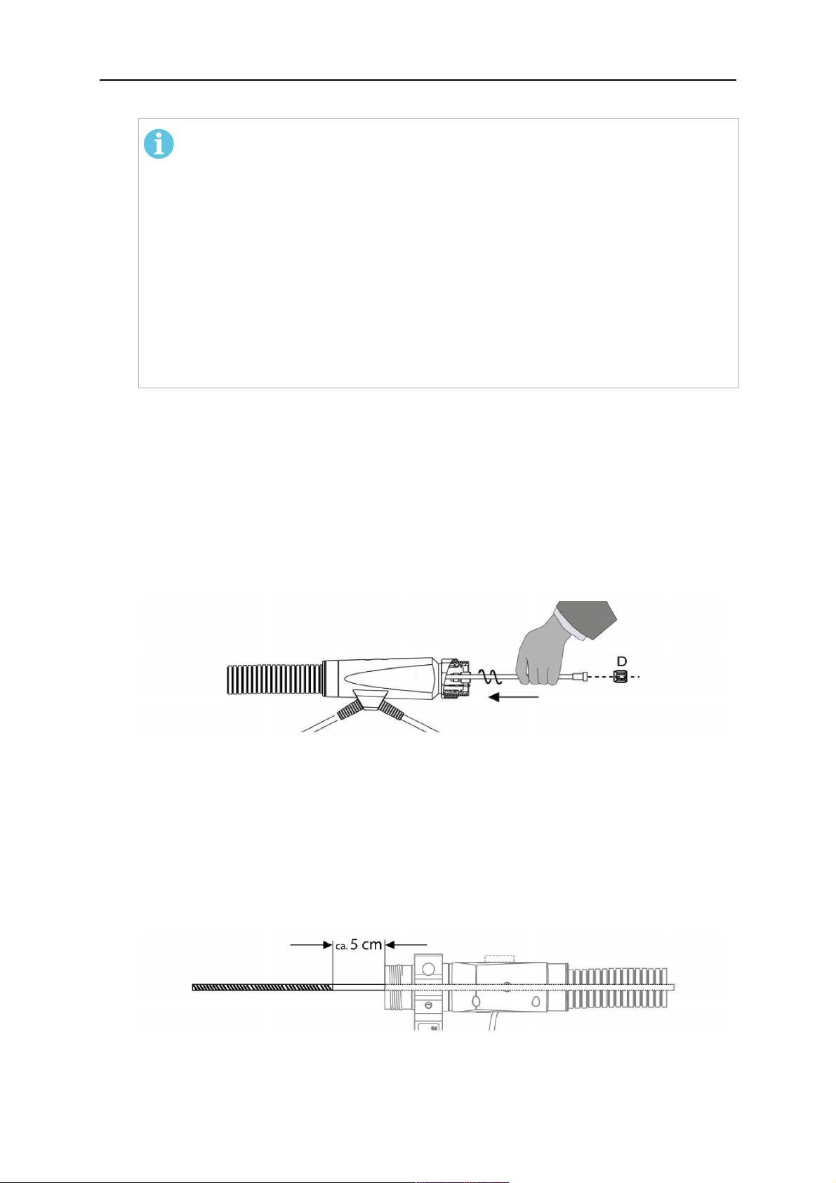
1. Install the torch (see section "Torch neck equipment").
2. Remove the gas nozzle and contact tip from the torch.
3. Remove the sleeve nut (D) from the Euro connector.
4. Push in the liner through the central connector and fix with the sleeve nut.
5. Cut off the liner flush with the nozzle holder. To determine the thread projection of the
contact tip, pull the liner backwards and screw in the contact tip.
6. Push the liner forwards as far as it will go to the contact tip applying light pressure on
the liner and measure the length to be shortened at the rear.
7. Now remove the liner again and cut the excess length measured off it’s front end. If
needed, grind down the burred edges. Make sure the inner opening of the liner is not
obstructed by the cut wire end.
8. The insulation of the liner must be removed after cutting off in the front area, such that
the insulation protrudes out of the RM2 flange by approx. 5 cm. For this, briefly
remove the torch neck.
9. Push the liner back in again and fix with the sleeve nut (D), see above. Re-install the
gas nozzle.
0463 373 101
- 51 -
© ESAB AB 2018
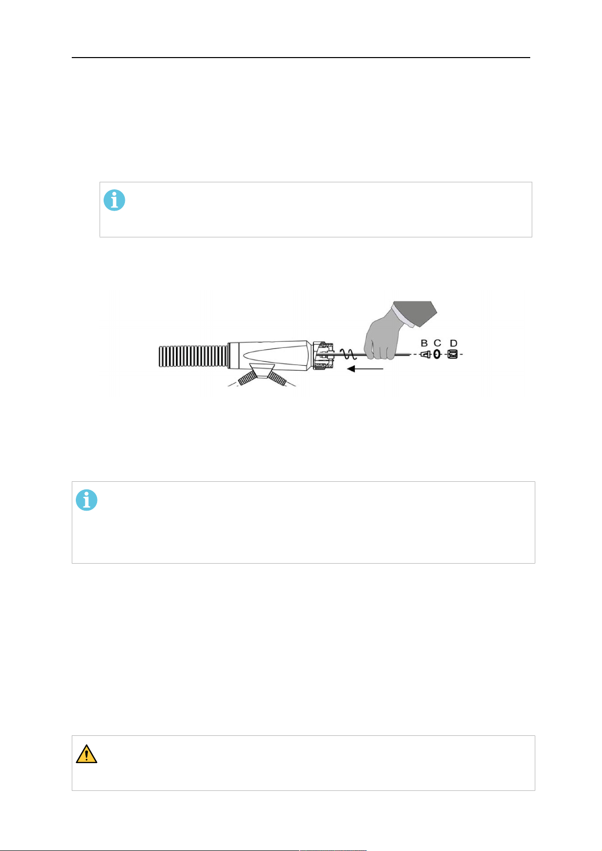
5 INSTALLATION
Installing a plastic liner
1. Mount the torch neck (see section "Torch neck equipment") and equip it with a gas
nozzle and contact tip.
2. Remove the sleeve nut (D) from the Euro connector.
3. Cleanly cut off the liner, slightly break the outer edges, point slightly (e.g. with a pencil
sharpener).
4. Insert the liner through the central connector into the cable assembly with fitted torch.
If it gets stuck, rotate the liner to free it and facilitate installation.
POZOR!
Make sure the liner is completely inserted by rotating it and slightly pushing it
forward, until you can feel it has reached its stop.
5. Mount the nipple (B) and the O-Ring (C), move it to the right position and fix it with the
sleeve nut (D) of the Euro central connector.
6. Measure the required overlap needed inside the wire feeder cabinet and cut the liner
accordingly.
5.7 Adjust the narrow gap contact tip
The adjusting tool RT42-NG is designed for the narrow gap torch necks RT42W-NG,
RT42G-NG and RT 82W-0°NG, torches with curved narrow gap contact tip. It facilitates the
precisely repeatable and fast changing of the curved contact tip.
POZOR!
The adjusting tool must be securely fastened to a stable base, in order to prevent
the position of the device in relation to the robot cannot change unintentionally. If the
exact orientation of the device is lost, the alignment of the contact tip used for the
elaboration of the welding programs can no longer be reproduced with precision.
Select a position within the operating range of the robot for orientation (alignment) of the
contact tip to the torch. Fasten the adjusting tool firmly to a base using the fastening grooves
provided for this purpose. Fastening material is not included with the adjusting tool. Select
fastening material (screws) to suit the existing conditions.
Save all motion sequences and stop positions required to change or align the wearing parts
to a separate robot program.
Before programming the welding tasks: plan at which orientation the contact tip is to stand in
relation to the torch. The torch must then be positioned in the desired rotational position and
the contact tip aligned using the adjusting device. Only then may the welding task be
programmed. If different orientations of the contact tip are required for various welding tasks,
the contact tip has to be aligned to the new position when the welding task is changed.
VAROVÁNÍ!
The gas nozzle and the torch head become very hot during welding. Always allow
the torch to cool down before replacing wearing parts or adjusting the contact tip.
0463 373 101
- 52 -
© ESAB AB 2018

5 INSTALLATION
Adjust the contact tip
Move the robot torch to a position parallel to
the opening of the adjusting tool (2). Maintain
a sufficient distance to the work table to be
able to comfortably remove the gas nozzle.
Define this position in your robot program as
the wearing parts change position (stop
position 1).
Remove the gas nozzle by pulling it
downwards. Remove the welding wire in the
contact tip if necessary.
Loosen the counter nut (4) of the contact tip
while counter-holding the nozzle holder at the
wrench flat (3).
Unscrew the contact tip including the counter
nut from the nozzle holder and replace the
nozzle holder if necessary.
Completely screw the counter nut (4) onto the
new contact tip. Screw the contact tip
including the counter nut into the nozzle
holder.
Align the contact tip until it is parallel to the
opening of the adjusting tool. If necessary,
slightly unscrew the contact tip so that it can
be easily turned in both directions.
0463 373 101
- 53 -
© ESAB AB 2018
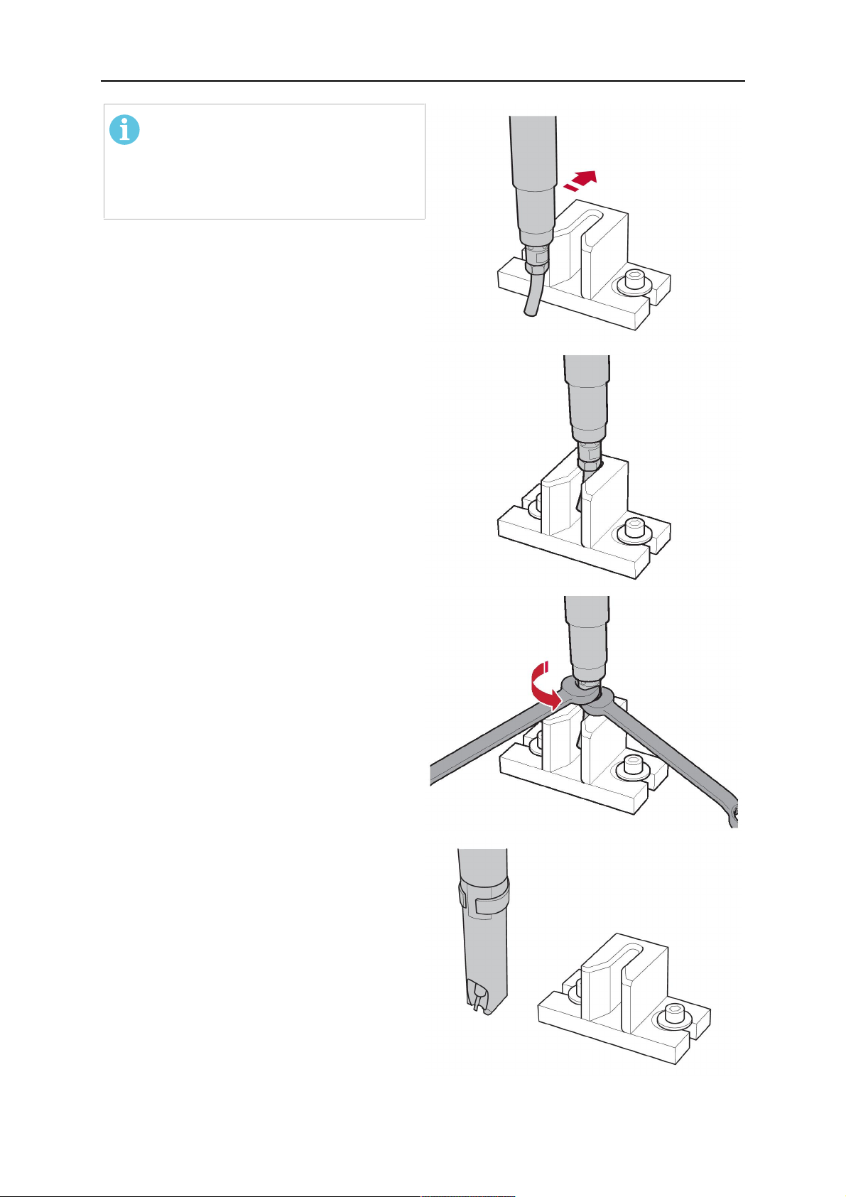
5 INSTALLATION
POZOR!
The contact tip must be able to be
easily moved by hand in both
directions in order to enable the
threading of the adjusting tool.
Place the robot torch or contact tip directly in
front of the opening of the adjusting tool (2)
(stop position 2).
Insert it slowly from the front until it is
completely inserted into the device (stop
position 3).
The contact tip was aligned exactly in the
device during insertion. Now cautiously
tighten the counter nut (4) in this position,
while counter holding the nozzle holder at the
wrench flat.
Slowly move the robot torch out of the
adjusting gauge, return to stop position 1 and
push on the gas nozzle as far as it will go.
Allow the welding wire to run into the contact
tip and bring the robot arm into welding
position.
0463 373 101
- 54 -
© ESAB AB 2018
6 OPERATION
6 OPERATION
UPOZORNĚNÍ!
Before starting the system, check the whole installation according to the
manufacturer's instructions and applicable safety regulations.
Check the following to make sure that the system has been installed correctly:
1. Are all parts securely attached (torch, torch mount, flanges, safety-off device, cable
assembly, and wire feeder cabinet)?
2. Are all media hoses connected correctly and protected from damage?
3. Is the EURO central connector or direct connector fastened tightly?
4. Is the cable assembly length correct and suitable for the installation and can the cable
rotate freely? The cable must not be bent sharply. Any risk of the cable getting caught
on another object must be eliminated.
5. Is the control cable of the safety-off circuit connected and functioning? Move torch by
hand to test (RTKSC-2 and RTKS-2 only).
6. Is the torch firmly attached and is it completely equipped?
7. Is the wire guide installed according to the manual?
8. Are all lines and tubes arranged so that they cannot be damaged or bent?
The wire run-in can now be started, either via the wire run-in pushbutton or via the wire run-in
at the feeder.
6.1 Important information for programming (hollow wrist system only)
Fast rotation of axis 6 of the robot will significantly stress the cable assembly. In certain
cases, this can lead to damage or destruction of the cable. In order to maximize the lifetime
of the cable, we strongly suggest respecting the following limitations when programming the
robot.
Position of axis 5 Max. rotational speed of axis 6
0 – 60° 100 % (no limitations)
60° – 80° 300°/sec (approximately 50 % of max. robot speed)
> 80° 120°/sec (approximately 20 % of max. robot speed)
POZOR!
The above values are only indications. For information on the exact rotational speed
limits, refer to the individual robot manual or contact the robot supplier.
To reposition the torch quickly, the robot arm may have to be slightly extended first to achieve
a bending angle of max. 60° of axis 5. In this position, the maximum available rotation speed
of axis 6 can be used.
When using the ESAB Helix cable assembly, the max. rotation of ±270° from the neutral
position must not be exceeded.
0463 373 101
- 55 -
© ESAB AB 2018
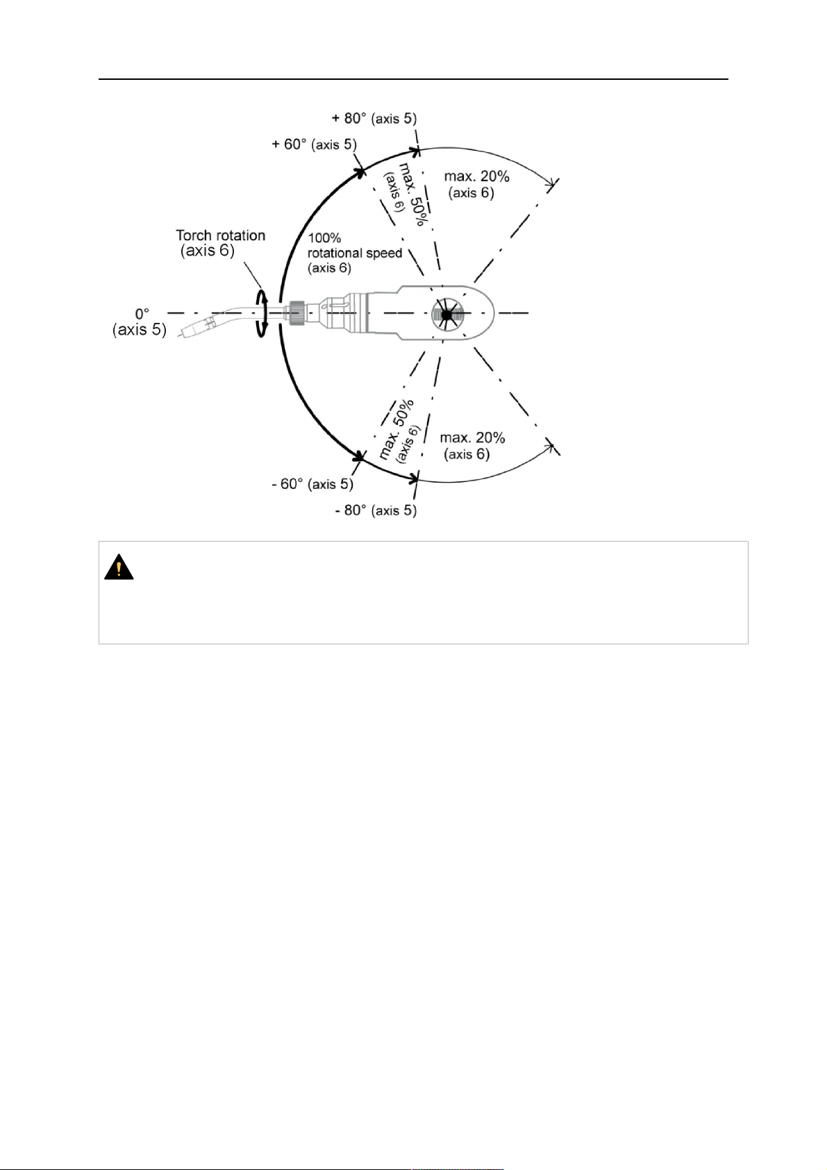
6 OPERATION
UPOZORNĚNÍ!
While axis 5 is bent more than 60°, the rotational speed of the torch around axis 6
must be limited, see table above.
Otherwise, the cable assembly may be damaged.
0463 373 101
- 56 -
© ESAB AB 2018
7 SERVIS AÚDRŽBA
7 SERVIS AÚDRŽBA
VAROVÁNÍ!
Než budete provádět údržbu systému, je nejprve nutné vypnout hlavní el. napájení.
Řiďte se bezpečnostními předpisy uvedenými na začátku této příručky!
Je zakázáno znovu používat poškozené hořáky či kabelové sestavy! Předtím než
zařízení znovu použijete, musí zjištěné závady opravit kvalifikovaný personál.
VAROVÁNÍ!
Riziko popálenin! Při svařování se plynová hubice ahlava hořáku ohřívají na vysoké
teploty. Nechte hořák zchladnout předtím, než budete provádět údržbové práce.
VAROVÁNÍ!
Abyste zabránili zranění osob nebo poškození instalace, postupujte podle
následujících pokynů:
1. Opravu úchytu hořákuRT KSC-2 neboRT FLC-2, bezpečnostního
vypínacího mechanismuRT KS-2, kabelové sestavy nebo spojky média
Infiniturn smí provádět pouze servisní podpora ESAB.
2. Spojka médií Infiniturn se nesmí nikdy otevírat. Spojka neobsahuje žádné
součásti, jejichž servis by mohl provádět uživatel, ademontáží by došlo
kjejímu zničení.
3. Nikdy nerozebírejte zařízeníRT KSC-2 neboRT KS-2. Jedná se o
pružinový mechanismus. Nesprávná manipulace může vést kvážnému
zranění.
7.1 Povinné kontroly aakce
Před každým použitím:
• Zkontrolujte, zda hořák, kontaktního špička, plynová hubice, vložka hrdla, kabely
acelkové vybavení nevykazují známky všeobecného poškození.
POZOR!
Aby se minimalizovala doba odstávky, doporučuje se střídat dvě hrdla hořáku,
přičemž vždy mějte kdispozici vybavené hrdlo hořáku, které je ihned připravené
kpoužití.
Každých 8hodin provozu (v závislosti na aplikaci):
• Vyměňte kontaktní špičku.
Denně:
• Rukou zkontrolujte funkčnost bezpečnostního vypínacího mechanismu.
• Proveďte vizuální kontrolu případného poškození– např. ohnutí nebo prasknutí.
• Zkontrolujte správnou polohu podavače drátu. Kabelová sestava nesmí být příliš
napnutá ani prohnutá.
• Zkontrolujte, zda nedochází kúniku ze spojky médií aspojky médií Infiniturn.
• Proveďte čištění aúdržbu hořáku podle pokynů vpříručce hořáku.
Každých 40hodin provozu (v závislosti na aplikaci):
• Vyměňte vložky drátu.
• Vyměňte vložky hrdla.
0463 373 101
- 57 -
© ESAB AB 2018

7 SERVIS AÚDRŽBA
Týdně nebo dle potřeby, vzávislosti na použití:
• Demontujte vodicí vložky drátu azkontrolujte, zda nejsou opotřebené nebo znečištěné.
Vpřípadě potřeby ji vyměňte.
Měsíčně nebo častěji při náročném používání (tj. více než 8hodin denně):
• Profoukněte kanál vodicí vložky drátu stlačeným vzduchem (odstraňte kontaktní špičku
avodicí vložku drátu).
• Zkontrolujte, zda jsou všechny šrouby utažené.
• Zkontrolujte všechny přípojky ahadice, zda nejsou poškozené.
• Vyměňte po 250kg veškerého svařovacího drátu.
Poškození elektrické izolace musí opravit vyškolení pracovníci. Teprve pak lze zařízení
bezpečně obsluhovat.
0463 373 101
- 58 -
© ESAB AB 2018

8 ŘEŠENÍ PROBLÉMŮ
8 ŘEŠENÍ PROBLÉMŮ
Závada Možná příčina Opatření
Nelze podávat
drát
Svařovací drát nebyl před
zavedením do kabelové sestavy
natažený.
Hořák akabelová sestava nejsou
správně vybaveny pro průměr
amateriál drátu.
Vodicí vložka drátu není správně
vložena do kabelové sestavy.
Kontaktní špička je zanesena
nečistotami z drátů
Vodicí vložka drátu je opotřebená
Podávání drátu je vhořáku
překážejí nečistoty azbytky
Je-li třeba, znovu svařovací drát
vytáhněte, odřízněte, odstraňte
otřepy zkonce anarovnejte prvních
10cm drátu. Poté jej provlékněte
zpět do kabelové sestavy.
Zkontrolujte vodicí vložku drátu
(kabelová sestava ahrdlo hořáku)
akontaktní špičku.
Povytáhněte vodicí vložku drátu
zkonektoru Euro. Při zavádění
vodicí vložky drátu byste měli cítit,
jak poslední centimetr vklouzne do
vodicího spojníku vrozhraní hořáku.
Vopačném případě může být vodicí
vložka drátu příliš krátká anebude
plně zasunuta.
Vyměňte kontaktní špičku nebo
vodicí vložku drátu, profoukněte
hrdlo hořáku, obvod vodicí vložky
drátu avodicí vložku drátu
stlačeným vzduchem.
Hořák se
nadměrně
zahřívá
Problémy při
podávání drátu
Kontaktní špička nebo úchyt špičky
nejsou správně utaženy
Použijte vhodný nástroj kutažení na
úroveň utažení rukou.
Chladicí systém nepracuje správně. Zkontrolujte průtok vody, výšku
hladiny ačistotu.
Chladicí systém není správně
připojen
Zkontrolujte přípojky (přívod
azpětný tok vody).
Hořák je přetížen. Řiďte se technickými údaji, aje-li
třeba, vyberte jiný typ.
Závada kabelové sestavy. Zkontrolujte kabely, potrubí
apřípojky.
Kontaktní špička je opotřebená. Vyměňte kontaktní špičku.
Vložka je opotřebená nebo
znečištěná.
Použitý spotřební materiál se
nehodí pro průměr drátu či materiál.
Zkontrolujte vložku aprofoukněte ji.
Vpřípadě potřeby ji vyměňte.
Zkontrolujte seznam náhradních
dílů.
Podavač není správně nastaven. Zkontrolujte podávací válec,
kontaktní tlak abrzdu cívky.
Kabelová sestava je ohnutá nebo
rozložená vpříliš malých
poloměrech.
Zkontrolujte, zda není kabelová
sestava poškozená. Lze vložku
zasunout snadno? Nainstalujte
podle pokynů. Viz část „Instalace
kabelové sestavy“.
0463 373 101
Drát je kontaminován. Použijte čisticí plst.
- 59 -
© ESAB AB 2018

8 ŘEŠENÍ PROBLÉMŮ
Závada Možná příčina Opatření
Během sváření
Cívka drátu je prázdná Zkontrolujte množství svařovacího
se podávání
drátu zastavilo
Došlo kzablokování drátu
vkabelové sestavě
Drát hoří zpět do kontaktní špičky
nebo je kontaktní špička opotřebena
Svařování se
zastavuje
Byl aktivován mechanismus
bezpečnostního vypnutí.
Póry ve svaru Plynový vír způsobený ulpíváním
rozstříkaného kovu
Příliš nízký nebo extrémně vysoký
průtok plynu vhořáku
Vadný přívod plynu Zkontrolujte průtokovou rychlost
Vlhkost nebo kontaminace na drátě
nebo na obrobku
drátu na cívce vpodavači.
Zkontrolujte podavač (možná je
příliš rychlý), zkontrolujte, zda není
kontaminována/ucpána kontaktní
špička. Je-li třeba, vyčistěte ji nebo
vyměňte.
Zkontrolujte kontaktní špičku.
Vyhledejte kolizní body aodstraňte
je. Zkontrolujte, zda se vřídicím
vedení nevyskytuje volný kontakt.
Vyčistěte hlavu hořáku, použijte
plynový difuzér/ ochranu proti
rozstřiku.
Zkontrolujte průtokovou rychlost
pomocí měřicího nástroje.
atěsnost.
Zkontrolujte drát aobrobek, použijte
méně kapalného prostředku proti
rozstřiku nebo jiný druh tohoto
prostředku.
Oblouk není
stabilní
Kontaktní špička je opotřebená. Vyměňte kontaktní špičku.
Špatné svářecí parametry Zkontrolujte nastavení svařovacího
vybavení.
Nedostatečná elektrická připojení
vobvodu.
Zkontrolujte, zda jsou veškerá
elektrická připojení (včetně kabelů
elektrického uzemnění) mezi
napájecím zdrojem hořáku
aobrobkem pevně usazená.
0463 373 101
- 60 -
© ESAB AB 2018

9 OBJEDNÁVÁNÍ NÁHRADNÍCH DÍLŮ
9 OBJEDNÁVÁNÍ NÁHRADNÍCH DÍLŮ
UPOZORNĚNÍ!
Opravy a elektrické práce musí provádět autorizovaný servisní technik ESAB.
Používejte pouze originální náhradní díly ESAB.
Hořáky ESABRT– modelyRTKS-2, RTFL-2, RT-KSC-2, RT-FLC-2, RT42, RT52, RT62,
RT72, RT82, RT42-NG aRT82WNG jsou navrženy atestovány vsouladu
smezinárodními aevropskými normami IEC/EN 60974-7. Servisní služba, která provedla
servis nebo opravu, musí zajistit, aby výrobek stále vyhovoval uvedené normě.
Náhradní díly a spotřební díly si můžete objednat u nejbližšího prodejce společnosti ESAB,
viz esab.com. Při objednávání uveďte typ výrobku, sériové číslo, označení a číslo
náhradního dílu podle seznamu náhradních dílů. To usnadní expedici a zajistí správnost
dodávky.
0463 373 101
- 61 -
© ESAB AB 2018

ESAB AB, Lindholmsallén 9, Box 8004, 402 77 Gothenburg, Sweden, Phone +46 (0) 31 50 90 00
http://manuals.esab.com
For contact information visit esab.com
 Loading...