


RT Robo Welding Torch System
Instruction manual
0463 373 001 GB 20131212


TABLE OF CONTENTS
1 SAFETY ................................................................................................................ 4
2 WARRANTY.......................................................................................................... 6
3 TECHNICAL DATA ............................................................................................... 7
3.1 Application............................................................................................................ 7
3.2 Compatibility ........................................................................................................ 7
3.3 Overview of the RT welding torch system.........................................................7
3.4 Specifications.......................................................................................................8
3.4.1 Field of use.........................................................................................................8
3.4.2 Torch rating ........................................................................................................ 8
3.4.3 Voltage rating .....................................................................................................9
3.4.4 Torch cooling circuit limits (water cooled version only) ...................................... 9
3.5 Selection of a suitable torch ...............................................................................9
3.6 Selection of a suitable torch mount for the torch neck....................................9
3.7 Conditions of intended use...............................................................................10
4 INSTALLATION................................................................................................... 11
4.1 Preparation ......................................................................................................... 11
4.2 Installing the RT KS-1 on the robot arm .......................................................... 11
4.3 Installation of torch mount................................................................................ 11
4.3.1 Direct mounting to KS-1 ................................................................................... 11
4.3.2 Installation of the mounting flange on the RT KS-1..........................................12
4.4 Cable assembly installation .............................................................................. 13
4.4.1 Installing the cable assembly (RT flange) in the torch mount ..........................13
4.5 Robot welding torch ..........................................................................................14
4.5.1 Equipping the torch neck.................................................................................. 14
4.5.2 Mounting the torch neck...................................................................................15
4.6 Wire guide installation in cable assembly ....................................................... 16
4.6.1 Installation of a split wire guide (cable assembly) ............................................16
4.6.2 Installation of a continuous wire guide (cable assembly) .................................17
4.7 Connection at the wire feeder cabinet .............................................................18
5 INITIAL OPERATION..........................................................................................20
6 SERVICING AND MAINTENANCE .................................................................... 21
7 SPARE PARTS LIST........................................................................................... 23
7.1 Robot Welding Torch ......................................................................................... 23
7.2 System components ..........................................................................................23
7.3 Wire Guides ........................................................................................................23
8 TROUBLESHOOTING ........................................................................................ 25
Rights reserved to alter specifications without notice.
0463 373 001 © ESAB AB 2013

1 SAFETY
1 SAFETY
Users of ESAB equipment have the ultimate responsibility for ensuring that anyone who
works on or near the equipment observes all the relevant safety precautions. Safety
precautions must meet the requirements that apply to this type of equipment. The following
recommendations should be observed in addition to the standard regulations that apply to
the workplace.
All work must be carried out by trained personnel well-acquainted with the operation of the
equipment. Incorrect operation of the equipment may lead to hazardous situations which can
result in injury to the operator and damage to the equipment.
1. Anyone who uses the equipment must be familiar with:
○ its operation
○ location of emergency stops
○ its function
○ relevant safety precautions
○ welding and cutting or other applicable operation of the equipment
2. The operator must ensure that:
○ no unauthorised person is stationed within the working area of the equipment when it
is started up
○ no-one is unprotected when the arc is struck or work is started with the equpment
3. The workplace must:
○ be suitable for the purpose
○ be free from drafts
4. Personal safety equipment:
○ Always wear recommended personal safety equipment, such as safety glasses,
flame-proof clothing, safety gloves
○ Do not wear loose-fitting items, such as scarves, bracelets, rings, etc., which could
become trapped or cause burns
5. General precautions:
○ Make sure the return cable is connected securely
○ Work on high voltage equipment may only be carried out by a qualified
electrician
○ Appropriate fire extinquishing equipment must be clearly marked and close at hand
○ Lubrication and maintenance must not be carried out on the equipment during
operation
0463 373 001
- 4 -
© ESAB AB 2013

1 SAFETY
WARNING!
Arc welding and cutting can be injurious to yourself and others. Take precautions
when welding and cutting. Ask for your employer's safety practices which should
be based on manufacturers' hazard data.
ELECTRIC SHOCK - Can kill
• Install and earth the unit in accordance with applicable standards
• Do not touch live electrical parts or electrodes with bare skin, wet gloves or
wet clothing
• Insulate yourself from earth and the workpiece
• Ensure your working stance is safe
FUMES AND GASES - Can be dangerous to health
• Keep your head out of the fumes
• Use ventilation, extraction at the arc, or both, to take fumes and gases away
from your breathing zone and the general area
ARC RAYS - Can injure eyes and burn skin
• Protect your eyes and body. Use the correct welding screen and filter lens
and wear protective clothing
• Protect bystanders with suitable screens or curtains
FIRE HAZARD
• Sparks (spatter) can cause fire. Make sure therefore that there are no
inflammable materials nearby
NOISE - Excessive noise can damage hearing
• Protect your ears. Use earmuffs or other hearing protection. Protect your
ears. Use earmuffs or other hearing protection
• Warn bystanders of the risk
MALFUNCTION - Call for expert assistance in the event of malfunction.
Read and understand the instruction manual before installing or operating.
PROTECT YOURSELF AND OTHERS!
CAUTION!
Read and understand the instruction manual before
installing or operating.
0463 373 001
- 5 -
© ESAB AB 2013

2 WARRANTY
2 WARRANTY
Before delivery, our products are carefully checked. We guarantee, that each product is free
from defects of material and workmanship at the time of delivery and is functioning according
to its intended use.
ESAB provides warranty on defects of material and workmanship according to legal
requirements. Consumables are exempt from this warranty.
The warranty does not cover any damages or functional defects resulting from
• overloading, abusing or diverting from intended use of the product
• collisions or accidents
• non compliance with instructions stated in these operating instructions
• improper installation or assembly
• insufficient maintenance
• modifying the product from its original state
• chemical influences
• normal wear and tear
ESAB assumes no liability other than for replacement or repair of faulty parts.
0463 373 001
- 6 -
© ESAB AB 2013

3 TECHNICAL DATA
3 TECHNICAL DATA
3.1 Application
The RT welding torch system is developed for fully-automatic MIG/MAG welding using
welding robots. Its components consist of:
• an RT welding torch
• cable assembly
• torch mount
• safety-off mechanism or rigid intermediate flange
It is possible to use gas or water cooling. For different needs in the welding process a large
selection of suitable torches with different geometries can be used.
3.2 Compatibility
Depending on the type of robot, an adapter flange is required for the assembly of the system
at the robot wrist. The robot should have a load-bearing capacity of at least approximately 5
kg at its wrist.
NOTE!
Correct selection of the system components to suit the welding task is the
prerequisite for the faultless functioning of the system.
3.3 Overview of the RT welding torch system
Item Description Function
1 RT welding torch Different versions available
A RT flange Interface to the RT welding torch
2 Cable assembly Different versions available, gas or water
cooled
3 Torch mount In various designs to fit the torch necks (for
example torch bent by 45°)
- Mounting flange (not shown) Only needed for some versions of the torch
mount (3)
(see "Installation" section)
0463 373 001
- 7 -
© ESAB AB 2013

3 TECHNICAL DATA
4 RT KS-1 Fully mechanical, spring supported safety-off
mechanism
Alternatively:
Rigid intermediate flange RT
FL-1
Rigid intermediate flange for robots with
electronic collision detection system, can be
used instead of the RT KS-1
(not shown)
5 Control plug Electrical connection to RT KS-1 for the signal
for collision monitoring
6 EURO central connector or
Connection to the wire feeder
other connector
7 Control cable with connecting
plug
Electrical connection for the safety-off signal
RT KS-1 (4-wire) and signal “nozzle sense”
(1-wire)
8 Blow out hose For cleaning the torch with compressed air
after welding
9 Water inlet (blue cap)
Water inlet for cooling of the torch
(water cooled version only)
10 Water return (red cap)
Water return of heated water from the torch
(water cooled version only)
3.4 Specifications
3.4.1 Field of use
The RT welding torches are intended for the use with CE-conform welding power sources for
the processes of metal inert gas welding (MIG), metal active gas welding (MAG) and metal
inert gas soldering with commercial round wires. Do not use the torch for other processes.
3.4.2 Torch rating
For detailed information regarding the rating and technical specifications of your torch please
see the spare parts list included with the torch. The ratings are valid for cable lengths from 1
to 5 m. The values for torch rating and duty cycle are valid for a 10 min. cycle.
The indicated ratings refer to a standardized case of use. In special cases, e.g. incase of an
especially high heat reflection on the torch, the torch may overheat at lower currents than
indicated. In this case, please use a more powerful model or reduce the duty cycle.
The rating will be notably reduced with the use of pulsed arc power sources.
Type of guidance Guidance by machine only
Weights
• Robot welding torch
• Cable assembly, 1,2 m long, G
• Cable assembly, 1,2 m long, W
• Torch Mount (Std.)
• RT KS-1
• RT FL-1
Approximately
• 0,66 kg
• 2,35 kg
• 2,35 kg
• 0,43 kg
• 1,96 kg
• 0,37 kg
Environmental temperature Storage -15° to 50°C (5° to 122°F)
Operation 5° to 40°C (41° to 104°F)
0463 373 001
- 8 -
© ESAB AB 2013

3 TECHNICAL DATA
Rating Cable assemblies
• gas cooled
• water cooled
Blow-out gas pressure max. 10 bar, separate gas hose
Rating/Duty cycle (Mixed gas, 10 min. cycle)
500 A/60 %, 350 A/100 %
600 A/100 %
3.4.3 Voltage rating
• The maximum permitted welding voltage for the system is 141 V (peak value).
• The maximum permitted voltage for the safety-off control circuit is 24 V, max 1 A, for the
push-button 48 V and max. 0,1 A
• The maximum permitted voltage for the push-button (cable assembly) is 48 V and max.
0,1 A
3.4.4 Torch cooling circuit limits (water cooled version only)
min. water flow rate: 1,0 l/min / 1,1 quarts/min
min. water pressure: 2,5 bar / 36,3 PSI
max. water pressure: 3,5 bar / 50,8 PSI
inlet temperature: max. 40°C / 104°F
return temperature: max. 60°C / 140°F
cooling capacity: min. 1000 W, depending on application
CAUTION!
Return temperatures of more than 60°C / 140°F may cause damage or destroy
the cable assembly. The cooler must always be filled with sufficient cooling liquid,
please consult the user manual of the cooling unit. In case of a high thermal load
on the torch, please use a cooler with sufficient capacity.
The ESAB products have been designed and manufactured according to the state-of-the-art.
They are safe and reliable when used according to their specifications. The RT torches are in
compliance with the European Norm IEC 60974-7 and marked with the CE-sign.
3.5 Selection of a suitable torch
The torch model must be chosen according to the welding application. The required
duty-cycle and capacity, the cooling method and the wire diameter have to be considered. If
there are increased requirements, for example caused by preheated work pieces, high heat
reflection in corners etc., these must be taken into account by choosing a welding torch with
adequate reserve in power rating.
3.6 Selection of a suitable torch mount for the torch neck
Torch mounts must always be selected in accordance with the type of torch and its geometry.
Various mount types may be used. Choosing the right one is important.
0463 373 001
- 9 -
© ESAB AB 2013

3 TECHNICAL DATA
3.7 Conditions of intended use
1. The product is intended for industrial and commercial use and must only be utilized by
trained personnel. The manufacturer is not liable for any damage or accidents resulting
from improper usage.
2. The RT System may solely be used for the purpose intended by the manufacturer within
the framework of its technical data and with automated handling systems. The type of
torch must be selected to suit the welding task. The maximum required duty cycle, load
capacity, type of cooling, type of guidance and wire diameter must be taken into
consideration for this. In case of higher demands, for example due to pre-heated
workpieces, high heat reflection in corners, etc. a type of torch must be selected with a
corresponding reserve capacity.
3. The RT System was designed for use as a complete system. The incorporation of
components from other manufacturers into the system is not permissible.
4. The RT System may only be installed, operated and serviced by trained personnel. The
installation, operation and maintenance regulations detailed in this manual are to be
followed.
5. The product must be kept dry and protected from humidity when transported, stored or
used.
6. The system is designed for environmental temperatures range from 5° and 40°C (41 to
104°F). In case these limits are exceeded, specific action is needed. In case of frost risks
use a suitable coolant.
0463 373 001
- 10 -
© ESAB AB 2013

4 INSTALLATION
4 INSTALLATION
4.1 Preparation
DANGER!
For you own safety, prior to starting maintenance work in the moving radius of the
robot, make sure that all necessary safety measures have been taken will stay
effective while in the danger area. Please refer to the chapter “Safety
instructions“ in the beginning of this manual.
The following assembly instructions must be exactly adhered to. Attention is to be paid
during assembly that the cables are not damaged. This can lead to a short circuit, which may
damage the electronics of the robot or the welding torch.
To obtain the best repeatability and stability of the system, only use original ESAB
components that have been specially developed for this purpose. Only then can the correct
functioning of the whole welding torch system be guaranteed.
4.2 Installing the RT KS-1 on the robot arm
Use the separate installation and operating instructions for the RT KS-1 safety-off
mechanism for installation of the RT KS-1 on the robot arm.
4.3 Installation of torch mount
Various mounts are available for mounting the RT torch. Depending on the design of the
mount, it may be attached directly or via a mounting flange (a) on the mounting surface (b) of
the safety-off mechanism RT KS-1 or, if applicable, on the intermediate flange RT FL-1.
Only torch mounts having a hole pattern coinciding with that of the mounting surface may be
attached.
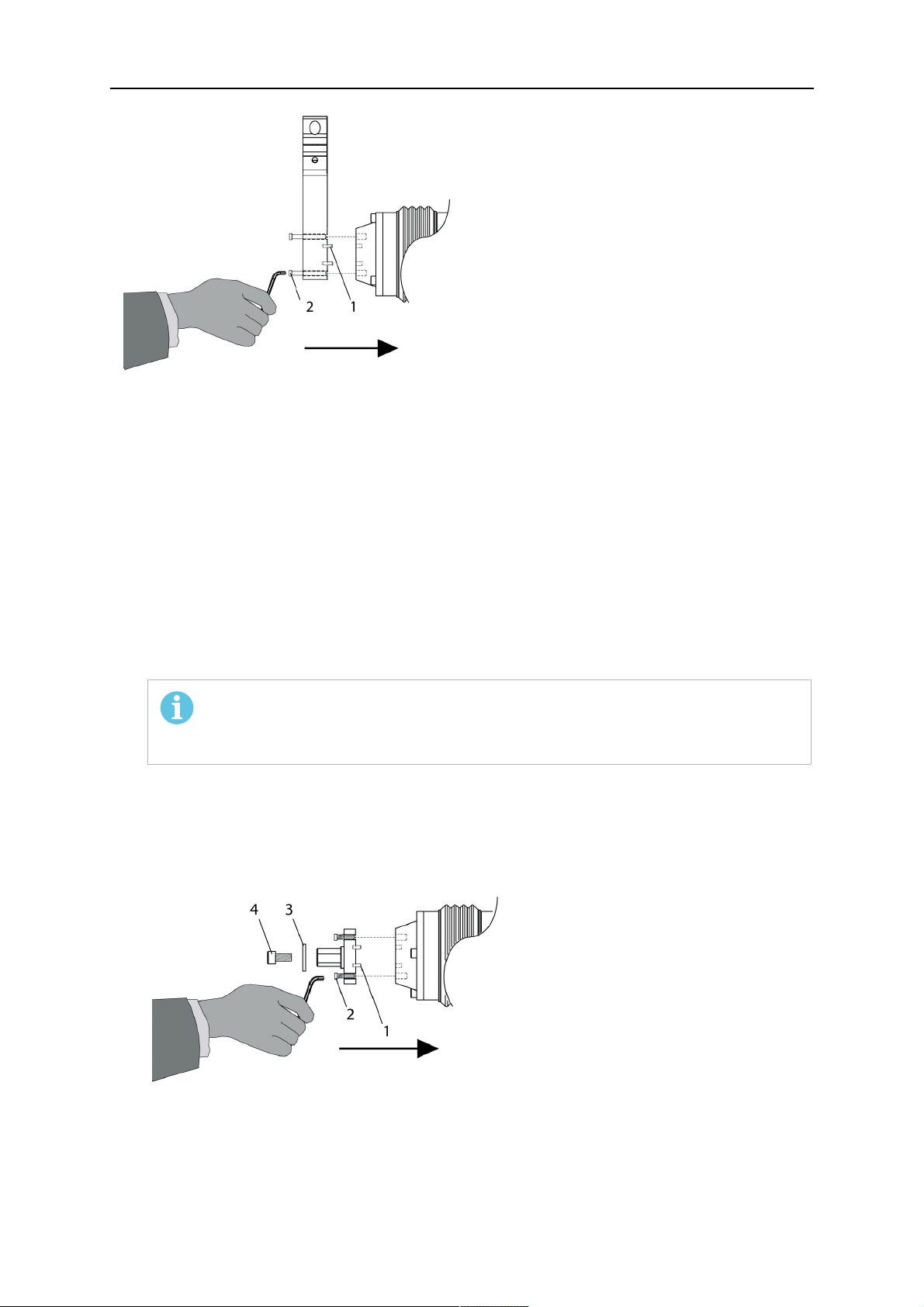
4.3.1 Direct mounting to KS-1
1. If necessary, carefully press the cylindrical pins (1) into the corresponding holes in the
bracket. Avoid the formation of burrs. The pins (Ø4×20) should protrude by
approximately 5 mm.
2. Position the mount on the safety-off mechanism KS-1 and carefully insert the cylindrical
pins (1) into the holes provided. In doing so, take the later position of the torch into
account; 2 mounting positions may be potentially possible.
3. Then screw down the mount evenly using the enclosed cylinder screws (M6×20) with
hexagon socket (2). For further information please refer to the RT KS-1 Installation and
Operating Instructions, Chapter “Installation of torch mount”.
0463 373 001
NOTE!
The maximum tightening torque for the cylinder screw is 7 Nm and the
property class category is 8.8.
- 11 -
© ESAB AB 2013
4 INSTALLATION
Side view
4.3.2 Installation of the mounting flange on the RT KS-1
Torch mounts with a central clamping assembly can only be fastened on the journal of the
mounting flange. For this, the mounting flange must be fastened first.
1. If applicable, carefully press the cylindrical pins (1) into the corresponding holes in the
mounting flange. Avoid the formation of burrs. The pins (Ø4×14) should protrude by
approximately 5 mm.
2. Position the mount on the safety-off mechanism RT KS-1 and carefully insert the
cylindrical pins (1) into the holes provided. In doing so, take the later position of the
torch into account; 2 mounting positions may be potentially possible.
3. Then screw down the mounting flange evenly using the enclosed cylinder screws
(M6×16) with hexagon socket (2). For further information please refer to the RT KS-1
Installation and Operating Instructions, Chapter “Installation of torch mount”.
NOTE!
The maximum tightening torque for the cylinder screws (M6×16) is 7.1 Nm
and the property class category is 8.8.
4. Unscrew the axial cylinder screw (M8×16) with hexagon socket (4) out of the mounting
flange together with the Ø9mm washer (3).
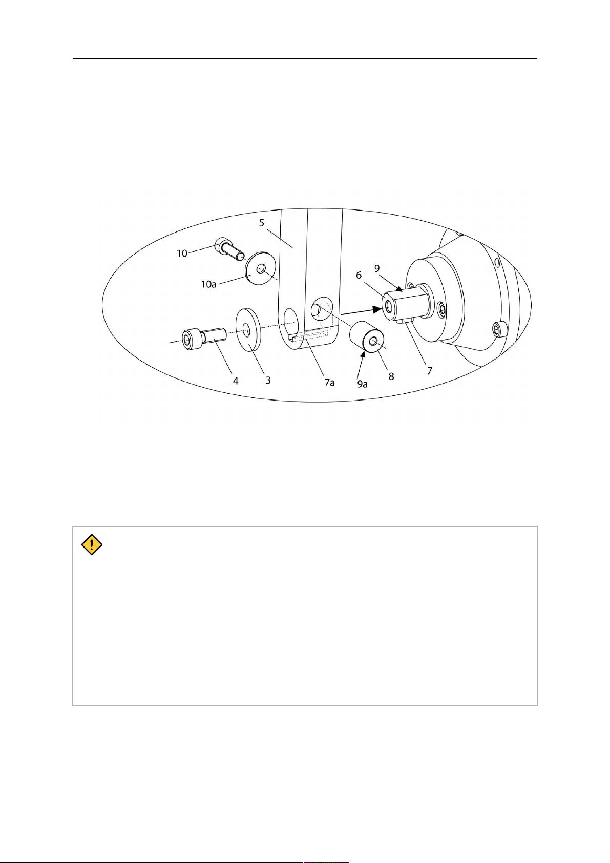
Top view
5. Place the torch mount (5) onto the journal (6) of the mounting flange, paying attention
while doing so to the exact alignment of the feather key (7) and the corresponding
groove (7a).
0463 373 001
- 12 -
© ESAB AB 2013
4 INSTALLATION
6. Insert the clamping mandrel (8) into the lateral hole (see illustration) and position it such
that the mating surfaces (9a) of the clamping mandrel rest on the mating surface (9) of
the journal.
7. Then fix the clamping mandrel from the opposite side using the cylinder screw (M6×30)
with hexagon socket (10) and the Ø22×6.4 mm washer (10a).
8. Finally, screw the axial cylinder screw (4) with the washer (3) into the mounting flange
and tighten firmly.
4.4 Cable assembly installation
The cable assembly must be aligned to the intended use in length and design. The type of
cooling for the torch and the cable assembly must be the same (either gas or water cooled
respectively). In order to prevent damage to the torch system and other components, it is
imperative to observe the following instructions.
CAUTION!
• Coordinate the length and design of the cable assembly to suit the range of
action of the robot.
• Do not bend, compress or overstretch the cable assembly.
• Fix the cable assembly such that is can be moved freely and cannot become
entangled.
• Any additional holding devices possibly installed, for example a balancer,
must not crush or bend the cable assembly.
• Extreme turning movements must be avoided in which the cable assembly
may become twisted.
• Chafing on the robot or other objects must be excluded.
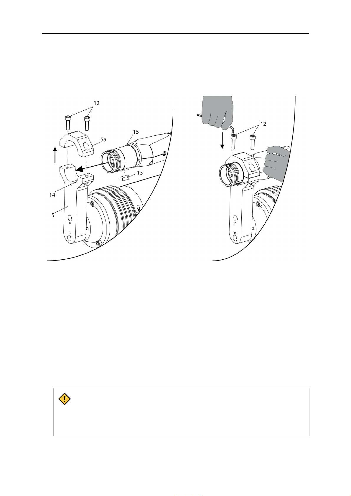
4.4.1 Installing the cable assembly (RT flange) in the torch mount
The front part of the cable assembly is directly clamped into the torch mount.
1. Unscrew the cylinder screws (12) and lift off the top section (5a) of the torch mount.
2. Insert the feather key (13) into the recess of the RT flange (cable assembly) from below.
0463 373 001
- 13 -
© ESAB AB 2013
4 INSTALLATION
3. Align the RT flange including the feather key (13) to the groove (14) of the torch mount
and push into the groove right up to the stop (15).
4. Hold the cable assembly in this position and simultaneously place the top section (5a)
back onto the torch mount. First screw both cylinder screws (12) loosely in to about the
same length, then tighten alternately. The top section (5a) of the mount should have an
even gap to the bottom section (see illustration below).
4.5 Robot welding torch
4.5.1 Equipping the torch neck
The torch must always be equipped to suit the wire diameter and material.
1. For this, select the correct wire guide, contact tip, nozzle holder, gas nozzle, gas diffuser
and spatter protection. You will find an exact overview and possible alternative
equipment elements for various torch models in the spare parts list of your torch. Only
use original ESAB parts; only then is the fitting accuracy ensured.
2. Firmly tighten the nozzle holder and the contact tip using a suitable tool for example the
enclosed monkey wrench.
3. When using a split wire guide, remove the installed guide nipple including the o-ring (16)
from the torch flange upon delivery if necessary (see illustration under
"Installation/removal of the wire guide in the torch neck in case of continuous wire
guidance" section)
CAUTION!
The torch must be completely equipped before welding, especially the gas
diffuser and/or spatter protection and all necessary insulators have to be
installed according to the spare parts list. Welding without these items may
cause immediate destruction of the torch.
Installation or replacement of the wire guide in the torch neck in the case of a separate
wire guide
0463 373 001
- 14 -
© ESAB AB 2013

4 INSTALLATION
The wire guide must be selected to fit the material and diameter of the welding wire. (See
spare parts list)
1. Unfasten sleeve nut and remove torch neck.
2. If applicable, loosen the screw connection of the connecting nipple and pull the neck liner
(wire guide) out of the torch neck from the rear.
3. Remove the gas nozzle and contact tip from the torch.
4. Blow down torch neck with compressed air.
5. Insert the new neck liner into the torch neck from the rear and fasten with the connecting
nipple. Cut the wire guide at the tip holder.
6. For the determination of the thread projection of the contact tip, loosen the connecting
nipple and pull the liner back again; then screw in the contact tip.
7. Insert the neck liner into the torch again until it reaches the contact tip. Now measure the
remaining length that needs to be cut from the liner.
8. Now remove the neck liner again and cut the additional length measured off it’s front
end. If needed, grind down the burred edges.
9. Insert the shortened neck liner into the torch neck again from the rear and screw in the
connecting nipple. Position or screw on the gas nozzle again.
10. Check o-rings on the flange of the torch neck for damage or wear, replace as required.
11. Mount the torch neck as described in "Mounting the torch neck" section. Do not use tools
to tighten the sleeve nut!
Installation/removal of the wire guide in the torch neck in case of continuous wire
guidance
A continuous wire guide, which reaches from the central connection of the cable assembly to
the contact tip of the torch, can be installed as an alternative to the separate wire guide. For
this, the description in "Wire guide installation in cable assembly" section applies. The guide
nipple including o-ring (16) must be inserted in the torch neck for this.
4.5.2 Mounting the torch neck
Check the o-rings on the flange of the torch neck before each mounting for damage or loss
and replace the o-rings if necessary. Missing or faulty o-rings lead to leaks of shielding gas
and coolant. Depending on the wire guide the torch neck must be equipped as described in
"Equipping the torch neck" section and the cable assembly as in "Installation of a split wire
guide (cable assembly)" section.
0463 373 001
- 15 -
© ESAB AB 2013

4 INSTALLATION
1. Position the torch necks as shown below and tighten the sleeve nut by hand in clockwise
direction. Do not use tools!
2. The correct seating of the torch at the RT flange of the cable assembly can be checked
by means of the window (11). If the torch has been correctly mounted, no gap should be
able to be seen through the window (11).
4.6 Wire guide installation in cable assembly
The wire guide is inserted through the cable assembly from the rear. The correct liner must
be selected to suit the filler material used and wire diameter. The correct function of the total
system can only be guaranteed if original ESAB wire guides are used. It is possible to use a
continuous wire guide from the cable assembly to the contact tip or a split wire guide (torch
neck extra, cable assembly extra).
4.6.1 Installation of a split wire guide (cable assembly)
Installing a steel liner
The wire guide is inserted through the cable assembly from the rear and reaches to the RT
flange. The following worksteps must be followed for the correct calculation of the length
(example for Euro central connector):
1. Install the guide nipple with stop (E) in the center hole of the RT flange.
2. Remove the sleeve nut (D) from the Euro connector.
3. Insert the liner through the central connection and push forwards as far as it will go in the
guide nipple (E) applying light pressure.
CAUTION!
Ensure that the wire guide has advanced right up to on the stop at the front.
To do this, rotate the wire guide and push forward again gently.
4. Now measure the excess length that needs to be cut from the liner.
0463 373 001
- 16 -
© ESAB AB 2013

4 INSTALLATION
5. Now remove the liner again and cut the additional length measured off it’s front end. If
needed, grind down the burred edges. Make sure the inner opening of the liner is not
obstructed by the cut wire end.
6. Reinstall the wire guide and attach the sleeve nut (D).
Installing a plastic liner
1. Install the guide nipple with stop (E) in the center hole of the RT flange.
2. Remove the sleeve nut (D) from the Euro connector.
3. Make a clean cut at the front end of the liner and chamfer the edges (for example with a
pencil sharpener).
4. Insert the liner (E) through the central connector into the cable assembly until it reaches
the stop. If it gets stuck, rotate the liner to free it and facilitate installation. Note: Make
sure the liner is completely inserted by rotating it and slightly pushing it forward, until you
can feel it has reached its stop.
5. Mount the nipple (B) and the o-ring (C), move it to the right position and fix it with the
sleeve nut (D) of the euro central connector.
6. Measure the required overlap needed inside the wire feeder cabinet and cut the liner
accordingly.
4.6.2 Installation of a continuous wire guide (cable assembly)
Installing a steel liner
The wire guide is inserted through the cable assembly from the rear and reaches to the
contact tip. The following worksteps must be followed for the correct calculation of the length
(example for Euro central connector):
1. Install the torch (see "Mounting the torch neck" section).
2. Remove the gas nozzle and contact tip from the torch.
3. Remove the sleeve nut (D) from the Euro connector.
4. Push in the liner through the central connector and fix with the sleeve nut.
5. Cut off the liner flush with the nozzle holder. To determine the thread projection of the
contact tip, pull the liner backwards and screw in the contact tip.
6. Push the liner forwards as far as it will go to the contact tip applying light pressure on the
liner and measure the length to be shortened at the rear.
7. Now remove the liner again and cut the excess length measured off it’s front end. If
needed, grind down the burred edges. Make sure the inner opening of the liner is not
obstructed by the cut wire end.
0463 373 001
- 17 -
© ESAB AB 2013

4 INSTALLATION
8. The insulation of the liner must be removed after cutting off in the front area, such that
the insulation protrudes out of the RT flange by approximately 5 cm. For this, briefly
remove the torch neck.
9. Push the liner back in again and fix with the sleeve nut (D). Re-install the gas nozzle.
Installing a plastic liner
1. Mount the torch neck (see "Mounting the torch neck" section) and equip it with a gas
nozzle and contact tip.
2. Remove the sleeve nut (D) from the Euro connector.
3. Cleanly cut off the liner, slightly break the outer edges, point slightly. (for example with a
pencil sharpener).
4. Insert the liner through the central connector into the cable assembly with fitted torch. If it
gets stuck, rotate the liner to free it and facilitate installation. Note: Make sure the liner is
completely inserted by rotating it and slightly pushing it forward, until you can feel it has
reached its stop.
5. Mount the nipple (B) and the o-ring (C), move it to the right position and fix it with the
sleeve nut (D) of the euro central connector.
6. Measure the required overlap needed inside the wire feeder cabinet and cut the liner
accordingly.
4.7 Connection at the wire feeder cabinet
In order to be able to create the connection, the cable assembly must be mounted as
described in "Cable assembly installation" section and equipped following "Wire guide
installation in cable assembly" section. Only then can the central and media connection take
place. Proceed as described below:
0463 373 001
- 18 -
© ESAB AB 2013

4 INSTALLATION
1. Connect the central connector of the cable assembly to the wire feeder cabinet socket.
Tighten the central connector sleeve nut fingertight. Do not use tools!
2. Connect the water hoses to the cooling circuit in water cooled systems. The end of the
hose marked blue to the water outlet, and the end marked red to the water return.
3. Connect the blow-out line to the corresponding connection of the wire feeder cabinet.
4. Connect the control line plug to the wire feeder cabinet.
0463 373 001
NOTE!
All hoses and the control line must be installed such that they cannot bend or be
damaged!
- 19 -
© ESAB AB 2013

5 INITIAL OPERATION
5 INITIAL OPERATION
CAUTION!
Before starting the system, check the whole installation according to the
manufacturer's instructions and applicable safety regulations.
Check the following to make sure that the system has been installed correctly:
1. Are all parts securely attached (torch, torch mount, cable assembly, RT KS-1 safety-off
mechanism or RT FL-1 rigid intermediate flange and wire feeder)?
2. Are all media hoses connected correctly and protected from damage?
3. Is the Euro central connector or direct connector fastened tightly?
4. Is the cable assembly length correct and suitable for the installation? The cable must not
be bent sharply, any risk of the cable catching on another object must be eliminated.
5. Is the safety-off circuit of the RT KS-1 connected correctly and functional? (move torch
by hand to test).
6. Is the torch firmly attached and is it completely equipped?
7. Is the wire guide installed according to the manual?
8. Are all lines and tubes arranged so they can not be damaged or bent?
Take the necessary safety precautions before starting up the welding process!
The wire run-in can now be started either via the wire run-in pushbutton (2a) see "Overview
of the RT welding torch system" section or via the wire run-in at the wire feeder cabinet.
0463 373 001
- 20 -
© ESAB AB 2013

6 SERVICING AND MAINTENANCE
6 SERVICING AND MAINTENANCE
DANGER!
• Before performing maintenance on the system, the main power of the
installation must be turned off. Note the safety regulations at the beginning of
this manual!
• Damaged torches or cable assemblies must no be used any more! Known
defects must be repaired by qualified personnel prior to the next use of the
equipment.
• In order to avoid damage to the system or injuries to persons, the following
must be observed: Repairs on the RT KS-1 safety-off mechanism may only
be carried out by ESAB!
DANGER!
Risk of burn injuries
Gas nozzle and torch head get very hot during welding. Let the torch cool down
prior to doing maintenance work!
To assure a faultless function and long life of the equipment, torch and cable assembly must
be checked and serviced regularly.
Cleaning and maintenance work must be done at the latest, if the welding performance is
degrading.
1. Check the torch and cable assembly for damages before every use. Damages must be
repaired by qualified personnel prior to further use of the product. This is especially
important in regard of damages on the electrical insulation of the torch or cable.
2. Worn out and damaged parts on the torch have to be exchanged immediately against
original spare parts and consumables.
3. The contact tip should be exchanged if the inner hole is countersunk or if there are
ignition problems.
4. Change the contact tip and the liner if there are wire feeding problems. Take care to
install the new liner correctly and precisely fit it to the length of the cable.
5. When changing the liner, or more often if necessary, blow out the liner guide tube of the
torch with compressed air to remove dust and wire grit.
6. The use of a high quality anti-spatter spray, for example RT Anti spatter liquid, is highly
recommended and will tremendously increase the life time of the consumables.
7. Contact tip and gas nozzle should be cleaned as soon as there is noticeable spatter
adhesion. It must be avoided that a spatter bridge will build up between contact tip and
gas nozzle, the torch could be damaged.
8. The gas nozzle should be cleaned regularly on the inside to prevent adhering spatter
from causing gas swirling.
9. Make sure that the cooling liquid is clean, if required exchange it. Impurities in the
cooling liquid can obstruct the water channels of the torch.
The following service intervals apply to the ESAB RT welding torch system:
Daily:
• Visual inspection for damages – for example bends or cracks.
• Verify the correct position of the cable assembly, it should be neither under tension, nor
compression.
• Inspect the media connections for leakage.
0463 373 001
- 21 -
© ESAB AB 2013

6 SERVICING AND MAINTENANCE
Monthly or more often in heavy use:
• Blow out the wire guide channel with compressed air (remove contact tip and wire
guide).
• Ascertain that all screws are tightened.
• If necessary: Inspect all connections and hoses for damages.
0463 373 001
- 22 -
© ESAB AB 2013

7 SPARE PARTS LIST
7 SPARE PARTS LIST
7.1 Robot Welding Torch
For spare and wearing parts, refer to the enclosed respective spare parts list of your RT
torch. Only use original ESAB parts; only then is the fitting accuracy ensured.
7.2 System components
Item Part No. Designation
4 700300434 RT KS-1 safety-off mechanism complete
17 on request Rubber boot for KS-1 safety-off mechanism
E on request Fitting with stop
18 on request Connector cover, red
19 on request Connector cover, blue
20 on request Quick connector (for water)
21 on request Quick connector 6 mm (for gas)
22 on request O-ring 4.0 x 1.0 mm (for gas)
23 on request O-ring 4.0 x 1.0 mm (for gas)
24 on request Nut M10x1
7.3 Wire Guides
Please choose the wire guide suitable for the wire diameter and material. Only use original
ESAB parts; only then is proper functioning ensured.
0463 373 001
- 23 -
© ESAB AB 2013

7 SPARE PARTS LIST
Item Part No. Designation
A (for steel wire) 700300498 Liner blue 1.50m, wire 0.8-1.0 mm
700300499 Liner blue 1.70m, wire 0.8-1.0 mm
700300500 Liner blue 2.00m, wire 0.8-1.0 mm
700300322 Liner blue 3.50m wire 0.8-1.0 mm
700300501 Liner red, 1.50m, wire 1.0-1.2 mm
700300502 Liner red, 1.70m, wire 1.0-1.2 mm
700300503 Liner red, 2.00m, wire 1.0-1.2 mm
700300507 Liner red, 2.50m, wire 1.0-1.2 mm
700300508 Liner red, 3.50m, wire 1.0-1.2 mm
700300504 Liner yellow, 1.50m, wire 1.2-1.6 mm
700300505 Liner yellow, 1.70m, wire 1.2-1.6 mm
700300506 Liner yellow, 2.00m, wire 1.2-1.6 mm
B (for alu and
stainless steel
700300320 PTFE Liner, 3.50m wire 1.0-1.2 mm
700300321 PA Liner, 3.50m, wire 1.0-1,2 mm
wire)
D (for alu and
stainless steel
700300468 Neck liner bronze, 217 mm, wire 1.2-1.6 mm
700300469 Neck liner steel, 217 mm, wire 0.8-1.2 mm
wire)
D (for steel wire) 700300470 Neck liner steel, 217 mm, wire 1.2-1.6 mm
700300472 Neck liner bronze, 217 mm, wire 0.8-1.0 mm
E 700300473 Fitting with stop size 4.0-4.7 mm
0463 373 001
- 24 -
© ESAB AB 2013

8 TROUBLESHOOTING
8 TROUBLESHOOTING
Fault Possible cause Action
Cannot feed in
the wire
Torch is
getting too hot
Have you straightened the welding
wire before feeding into the cable
assembly?
Were the RT torch and the cable
assembly equipped correctly for the
wire diameter and wire material?
Only when using a split wire guide:
Has the wire guide been correctly
inserted into the cable assembly?
Is the contact tip blocked with wire
debris or the wire guide worn, is the
wire feed impeded by dirt and debris
in the torch?
Contact tip or tip holder are not
tightened correctly.
If necessary, pull the welding wire
out again, cut off and deburr the end
and straighten the first 10 cm of the
wire. Then thread back into the
cable assembly.
Check wire guide (cable assembly
and torch neck) and the contact tip.
Pull the wire guide a short way out of
the Euro-connector. When inserting
you should feel the last centimetre
slip into the guide nipple in the torch
interface. Otherwise the wire guide
may be too short and not fully
inserted.
Replace the contact tip and/or wire
guide, blow out torch neck, wire
guide conduit and wire guide with
compressed air.
Use a suitable tool for tightening
hand-tight.
Wire feeding
problems
Cooling system is not working well. Check water flow, filling level and
cleanliness.
Cooling system is not correctly
connected.
Check connections (water inlet and
return).
Torch overstrained. Observe technical data, if needed,
choose a different type.
Cable assembly defective. Check cables, tubes and
connections.
Contact tip is worn. Exchange contact tip.
Liner is worn / dirty. Check the liner, blow it out, if needed
exchange it.
Consumables used are not suitable
Check with spare part list.
for the wire diameter or material.
Wire feeder not set-up properly. Check the wire feeding rolls, the
contact pressure and the spool
brake.
Cable assembly is bent or laid out in
too small radii or flexed.
Check the cable assembly for
damages. Can the liner be inserted
easily? Install as instructed (see
"Cable assembly installation"
section).
0463 373 001
Wire is contaminated. Use a cleaning felt.
- 25 -
© ESAB AB 2013

8 TROUBLESHOOTING
Wire feed
stops during
welding
Welding
process is
stopping
Pores in the
seam
Wire spool is empty? Check the quantity of the welding
wire on the spool in the wire feeder.
Is there a wire blockage in the cable
assembly?
Check wire feed (possibly too fast),
check the contact tip for
contamination/clogging, clean or
replace the contact tip if required.
Wire burn back into the contact tip or
Replace the contact tip.
worn contact tip.
Safety-off mechanism has triggered. Search for collision points and
prevent them. Check control line for
a loose contact .
Safety-off mechanism has triggered
without collision.
Gas swirl caused by spatter
adherence.
Too small or extremely high gas flow
in the torch.
Check control line for cable
breakage/loose contact.
Clean the torch head, use gas
diffuser/spatter protection.
Check flow rate with measurement
tool.
Gas supply defective. Check flow rate and possible
leakage.
Moisture or contamination on the
wire or on the work piece.
Check the wire and the work piece,
use less or different antispatter
liquid.
Arc is not
stable
Contact tip is worn. Exchange contact tip.
Wrong welding parameters. Check the set-up of the welding
torch.
Insufficient electrical connections in
the circuit.
Check all electrical connections
(including ground cable) between
the power source torch or workpiece
for firm seating.
0463 373 001
- 26 -
© ESAB AB 2013

8 TROUBLESHOOTING
0463 373 001
- 27 -
© ESAB AB 2013

ESAB subsidiaries and representative offices
Europe
AUSTRIA
ESAB Ges.m.b.H
Vienna-Liesing
Tel: +43 1 888 25 11
Fax: +43 1 888 25 11 85
BELGIUM
S.A. ESAB N.V.
Brussels
Tel: +32 2 745 11 00
Fax: +32 2 745 11 28
BULGARIA
ESAB Kft Representative Office
Sofia
Tel: +359 2 974 42 88
Fax: +359 2 974 42 88
THE CZECH REPUBLIC
ESAB VAMBERK s.r.o.
Vamberk
Tel: +420 2 819 40 885
Fax: +420 2 819 40 120
DENMARK
Aktieselskabet ESAB
Herlev
Tel: +45 36 30 01 11
Fax: +45 36 30 40 03
FINLAND
ESAB Oy
Helsinki
Tel: +358 9 547 761
Fax: +358 9 547 77 71
GREAT BRITAIN
ESAB Group (UK) Ltd
Waltham Cross
Tel: +44 1992 76 85 15
Fax: +44 1992 71 58 03
ESAB Automation Ltd
Andover
Tel: +44 1264 33 22 33
Fax: +44 1264 33 20 74
FRANCE
ESAB France S.A.
Cergy Pontoise
Tel: +33 1 30 75 55 00
Fax: +33 1 30 75 55 24
GERMANY
ESAB GmbH
Solingen
Tel: +49 212 298 0
Fax: +49 212 298 218
HUNGARY
ESAB Kft
Budapest
Tel: +36 1 20 44 182
Fax: +36 1 20 44 186
ITALY
ESAB Saldatura S.p.A.
Bareggio (Mi)
Tel: +39 02 97 96 8.1
Fax: +39 02 97 96 87 01
THE NETHERLANDS
ESAB Nederland B.V.
Amersfoort
Tel: +31 33 422 35 55
Fax: +31 33 422 35 44
NORWAY
AS ESAB
Larvik
Tel: +47 33 12 10 00
Fax: +47 33 11 52 03
POLAND
ESAB Sp.zo.o.
Katowice
Tel: +48 32 351 11 00
Fax: +48 32 351 11 20
PORTUGAL
ESAB Lda
Lisbon
Tel: +351 8 310 960
Fax: +351 1 859 1277
ROMANIA
ESAB Romania Trading SRL
Bucharest
Tel: +40 316 900 600
Fax: +40 316 900 601
RUSSIA
LLC ESAB
Moscow
Tel: +7 (495) 663 20 08
Fax: +7 (495) 663 20 09
SLOVAKIA
ESAB Slovakia s.r.o.
Bratislava
Tel: +421 7 44 88 24 26
Fax: +421 7 44 88 87 41
SPAIN
ESAB Ibérica S.A.
Alcalá de Henares (MADRID)
Tel: +34 91 878 3600
Fax: +34 91 802 3461
SWEDEN
ESAB Sverige AB
Gothenburg
Tel: +46 31 50 95 00
Fax: +46 31 50 92 22
ESAB International AB
Gothenburg
Tel: +46 31 50 90 00
Fax: +46 31 50 93 60
SWITZERLAND
ESAB AG
Dietikon
Tel: +41 1 741 25 25
Fax: +41 1 740 30 55
UKRAINE
ESAB Ukraine LLC
Kiev
Tel: +38 (044) 501 23 24
Fax: +38 (044) 575 21 88
North and South America
ARGENTINA
CONARCO
Buenos Aires
Tel: +54 11 4 753 4039
Fax: +54 11 4 753 6313
BRAZIL
ESAB S.A.
Contagem-MG
Tel: +55 31 2191 4333
Fax: +55 31 2191 4440
CANADA
ESAB Group Canada Inc.
Missisauga, Ontario
Tel: +1 905 670 02 20
Fax: +1 905 670 48 79
MEXICO
ESAB Mexico S.A.
Monterrey
Tel: +52 8 350 5959
Fax: +52 8 350 7554
USA
ESAB Welding & Cutting
Products
Florence, SC
Tel: +1 843 669 44 11
Fax: +1 843 664 57 48
Asia/Pacific
AUSTRALIA
ESAB South Pacific
Archerfield BC QLD 4108
Tel: +61 1300 372 228
Fax: +61 7 3711 2328
CHINA
Shanghai ESAB A/P
Shanghai
Tel: +86 21 2326 3000
Fax: +86 21 6566 6622
INDIA
ESAB India Ltd
Calcutta
Tel: +91 33 478 45 17
Fax: +91 33 468 18 80
INDONESIA
P.T. ESABindo Pratama
Jakarta
Tel: +62 21 460 0188
Fax: +62 21 461 2929
JAPAN
ESAB Japan
Tokyo
Tel: +81 45 670 7073
Fax: +81 45 670 7001
MALAYSIA
ESAB (Malaysia) Snd Bhd
USJ
Tel: +603 8023 7835
Fax: +603 8023 0225
SINGAPORE
ESAB Asia/Pacific Pte Ltd
Singapore
Tel: +65 6861 43 22
Fax: +65 6861 31 95
SOUTH KOREA
ESAB SeAH Corporation
Kyungnam
Tel: +82 55 269 8170
Fax: +82 55 289 8864
UNITED ARAB EMIRATES
ESAB Middle East FZE
Dubai
Tel: +971 4 887 21 11
Fax: +971 4 887 22 63
Africa
EGYPT
ESAB Egypt
Dokki-Cairo
Tel: +20 2 390 96 69
Fax: +20 2 393 32 13
SOUTH AFRICA
ESAB Africa Welding & Cutting
Ltd
Durbanvill 7570 - Cape Town
Tel: +27 (0)21 975 8924
Distributors
For addresses and phone
numbers to our distributors in
other countries, please visit our
home page
www.esab.com
www.esab.com
 Loading...