

ESAB Renegade ET 300i, Renegade ET 300iP Instruction Manual
Instruction manual
0463 416 001 GB 20171016
Valid for: serial no. 721-, 742-xxx-xxxx
ET300i, ET300iP
Welding power source TIG 300A

TABLE OF CONTENTS
0463 416 001 © ESAB AB 2017
1
SAFETY ......................................................................................................... 5
1.1 Meaning of symbols ................................................................................. 5
1.2 Safety precautions ................................................................................... 5
2
INTRODUCTION............................................................................................ 8
2.1 Overview ................................................................................................... 8
2.2 Equipment ................................................................................................. 8
3
TECHNICAL DATA ........................................................................................ 9
4
INSTALLATION.............................................................................................. 11
4.1 Location .................................................................................................... 11
4.2 Lifting instructions ................................................................................... 11
4.3 Mains supply............................................................................................. 12
4.4 Recommended fuse sizes and minimum cable area ............................ 15
5
OPERATION .................................................................................................. 17
5.1 Overview ................................................................................................... 17
5.2 Connections and control devices ........................................................... 17
5.3 TIG welding ............................................................................................... 18
5.4 MMA welding............................................................................................. 18
5.5 Connection of welding and return cables .............................................. 18
5.6 Turning the mains power on/off .............................................................. 18
5.7 Connect to cooler EC 1000 ...................................................................... 19
5.8 Fan control ................................................................................................ 19
5.9 Thermal protection ................................................................................... 20
5.10 Voltage reducing device (VRD) ............................................................... 20
5.11 Remote control ......................................................................................... 20
5.12 USB connection........................................................................................ 20
6
CONTROL PANEL......................................................................................... 21
6.1 ET 300i ....................................................................................................... 21
6.1.1 Navigation .............................................................................................. 21
6.1.2 Weld program ......................................................................................... 22
6.2 ET 300iP .................................................................................................... 23
6.2.1 Navigation .............................................................................................. 24
6.3 TIG settings............................................................................................... 25
6.3.1 Hidden TIG functions.............................................................................. 26
6.3.2 Measured values.................................................................................... 26
6.4 TIG functions explanation ....................................................................... 26
6.4.1 Foot pedal functions explanation............................................................ 28
6.5 MMA settings ............................................................................................ 30
6.5.1 Hidden MMA functions ........................................................................... 30
6.5.2 Measured values.................................................................................... 26
6.6 MMA functions explanation ..................................................................... 31

TABLE OF CONTENTS
0463 416 001 © ESAB AB 2017
7
MAINTENANCE............................................................................................. 32
7.1 Routine maintenance ............................................................................... 32
7.2 Cleaning instruction................................................................................. 32
8
TROUBLESHOOTING ................................................................................... 36
9
ERROR CODES............................................................................................. 37
9.1 Error code descriptions .......................................................................... 37
10
ORDERING SPARE PARTS.......................................................................... 39
DIAGRAM ............................................................................................................. 40
ORDERING NUMBERS ....................................................................................... 41
ACCESSORIES .................................................................................................... 42
Rights reserved to alter specifications without notice.
1 SAFETY
0463 416 001
- 5 -
© ESAB AB 2017
1 SAFETY
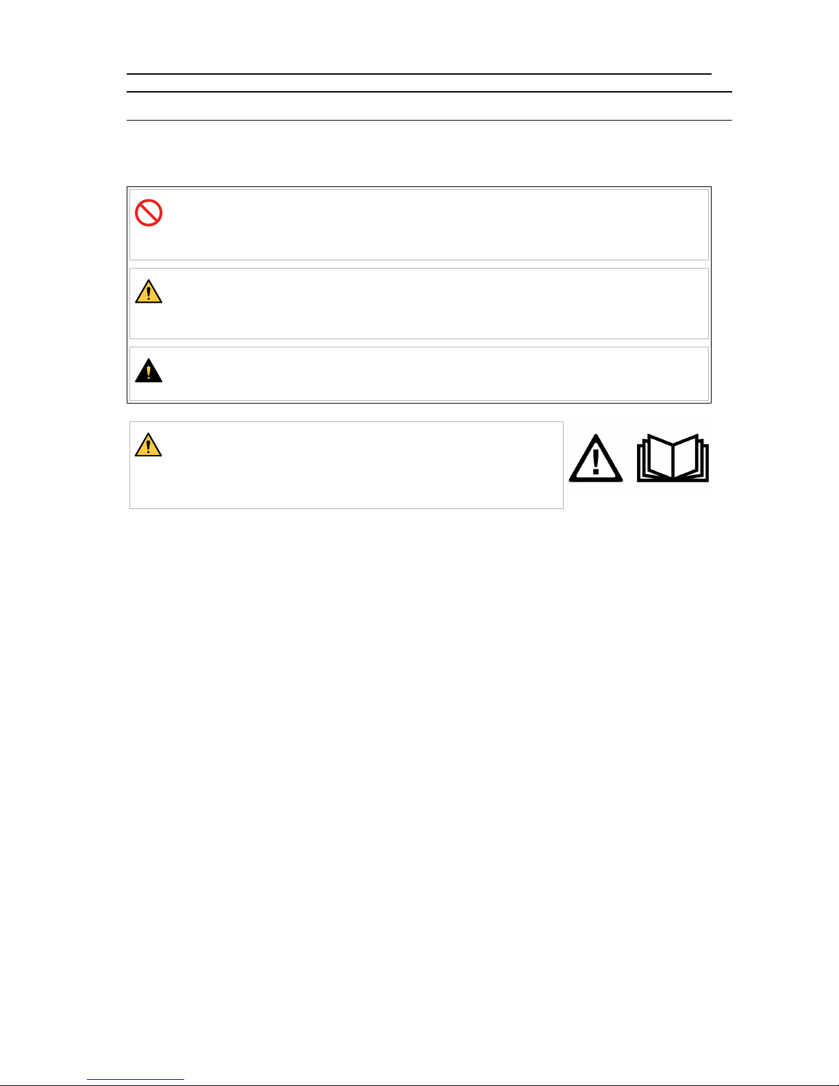
1.1 Meaning of symbols
As used throughout this manual: Means Attention! Be Alert!
DANGER!
Means immediate hazards which, if not avoided, will result in immediate,
serious personal injury or loss of life.
WARNING!
Means potential hazards which could result in personal injury or loss of
life.
CAUTION!
Means hazards which could result in minor personal injury.
WARNING!
Before use, read and understand the instruction manual
and follow all labels, employer´s safety practices and Safety
Data Sheets (SDSs).
1.2 Safety precautions
Users of ESAB equipment have the ultimate responsibility for ensuring that anyone who
works on or near the equipment observes all the relevant safety precautions. Safety
precautions must meet the requirements that apply to this type of equipment. The following
recommendations should be observed in addition to the standard regulations that apply to
the workplace.
All work must be carried out by trained personnel well-acquainted with the operation of the
equipment. Incorrect operation of the equipment may lead to hazardous situations which can
result in injury to the operator and damage to the equipment.
1. Anyone who uses the equipment must be familiar with:
○ its operation
○ location of emergency stops
○ its function
○ relevant safety precautions
○ welding and cutting or other applicable operation of the equipment
2. The operator must ensure that:
○ no unauthorised person is stationed within the working area of the equipment
when it is started up
○ no-one is unprotected when the arc is struck or work is started with the
equipment
3. The workplace must:
○ be suitable for the purpose
○ be free from drafts
1 SAFETY
0463 416 001
- 6 -
© ESAB AB 2017
4. Personal safety equipment:
○ Always wear recommended personal safety equipment, such as safety glasses,
flame-proof clothing, safety gloves
○ Do not wear loose-fitting items, such as scarves, bracelets, rings, etc., which
could become trapped or cause burns
5. General precautions:
○ Make sure the return cable is connected securely
○ Work on high voltage equipment may only be carried out by a qualified
electrician
○ Appropriate fire extinguishing equipment must be clearly marked and close at
hand
○ Lubrication and maintenance must not be carried out on the equipment during
operation
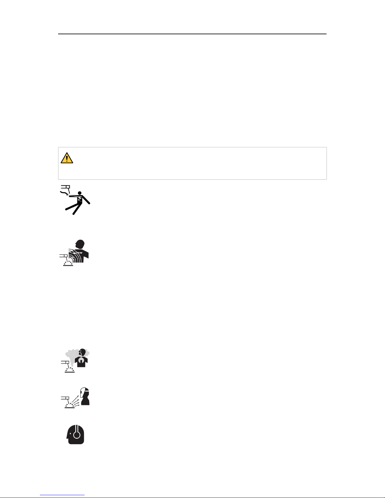
WARNING!
Arc welding and cutting can be injurious to yourself and others. Take precautions
when welding and cutting.
ELECTRIC SHOCK - Can kill
• Install and ground the unit in accordance with instruction manual.
• Do not touch live electrical parts or electrodes with bare skin, wet gloves or
wet clothing.
• Insulate yourself from work and ground.
• Ensure your working position is safe
ELECTRIC AND MAGNETIC FIELDS - Can be dangerous to health
• Welders having pacemakers should consult their physician before welding.
EMF may interfere with some pacemakers.
• Exposure to EMF may have other health effects which are unknown.
• Welders should use the following procedures to minimize exposure to
EMF:
○ Route the electrode and work cables together on the same side of
your body. Secure them with tape when possible. Do not place your
body between the torch and work cables. Never coil the torch or
work cable around your body. Keep welding power source and
cables as far away from your body as possible.
○ Connect the work cable to the workpiece as close as possible to the
area being welded.
FUMES AND GASES - Can be dangerous to health
• Keep your head out of the fumes.
• Use ventilation, extraction at the arc, or both, to take fumes and gases
away from your breathing zone and the general area.
ARC RAYS - Can injure eyes and burn skin
• Protect your eyes and body. Use the correct welding screen and filter lens
and wear protective clothing.
• Protect bystanders with suitable screens or curtains.
NOISE - Excessive noise can damage hearing
Protect your ears. Use earmuffs or other hearing protection.

1 SAFETY
0463 416 001
- 7 -
© ESAB AB 2017
MOVING PARTS - Can cause injuries
• Keep all doors, panels and covers closed and securely in place. Have only
qualified people remove covers for maintenance and troubleshooting as
necessary. Reinstall panels or covers and close doors when service is
finished and before starting engine.
• Stop engine before installing or connecting unit.
• Keep hands, hair, loose clothing and tools away from moving parts.
FIRE HAZARD
• Sparks (spatter) can cause fire. Make sure that there are no inflammable
materials nearby.
• Do not use on closed containers.
MALFUNCTION - Call for expert assistance in the event of malfunction.
PROTECT YOURSELF AND OTHERS!
CAUTION!
This product is solely intended for arc welding.
WARNING!
Do not use the power source for thawing frozen pipes.
CAUTION!
Class A equipment is not intended for use in residential
locations where the electrical power is provided by the
public low-voltage supply system. There may be potential
difficulties in ensuring electromagnetic compatibility of class
A equipment in those locations, due to conducted as well
as radiated disturbances.
NOTE!
Dispose of electronic equipment at the recycling
facility!
In observance of European Directive 2012/19/EC on Waste
Electrical and Electronic Equipment and its implementation
in accordance with national law, electrical and/or electronic
equipment that has reached the end of its life must be
disposed of at a recycling facility.
As the person responsible for the equipment, it is your
responsibility to obtain information on approved collection
stations.
For further information contact the nearest ESAB dealer.
ESAB has an assortment of welding accessories and personal protection equipment
for purchase. For ordering information contact your local ESAB dealer or visit us on
our website.

2 INTRODUCTION
0463 416 001
- 8 -
© ESAB AB 2017
2 INTRODUCTION
2.1 Overview
The ET300i and ET300iP are welding power sources intended for TIG welding and for
welding with covered electrodes (MMA).
ESAB accessories for the product can be found in the "ACCESSORIES" chapter of
this manual.
2.2 Equipment
The power source is supplied with:
• Instruction manual
• 3 m (9.8 ft) mains cable with plug
• Gas hose for TIG welding, including hose clamps
• Return cable

3 TECHNICAL DATA
0463 416 001
- 9 -
© ESAB AB 2017
3 TECHNICAL DATA
ET 300i (0445 100 900), ET300iP(0445100920)
Mains voltage 230–480 V ±10%,
3~50/60Hz
230 V ±10%, 1~50/60Hz
Mains supply S
sc min
4.1 MVA No demand
Z
max
0.04 Ohm No demand
Primary current
I
max
MMA 30.0 A 29.0 A
I
max
TIG 22.0 A 20.0 A
No-load power demand when in the energy-saving mode
Uin230 V 63 W 74 W
Uin400 V 68 W
Uin480 V 72 W
Setting range
MMA 5 A / 20 V - 300 A / 32 V 5 A / 20 V - 200 A / 28 V
TIG 5 A / 10 V - 300 A / 22 V 5 A / 10 V - 200 A / 18 V
Permissible load at MMA
40% duty cycle 300 A / 32.0 V
60% duty cycle 250 A / 30.0 V
100% duty cycle 200 A / 28.0 V 200 A / 28.0 V
Permissible load at TIG
40% duty cycle 300 A / 22.0 V
60% duty cycle 250 A / 20.0 V
100% duty cycle 200 A / 18.0 V 200 A / 18.0 V
Power factor at maximum current
TIG 0.96 0.98
MMA 0.96 0.99
Apparent power I2at
maximum current
11.6 kVA 6.6 kVA
Active power I2at maximum
current
11.2 kW 6.6 kW
Efficiency at maximum current
TIG 83% 83%
MMA 86% 86%
Open-circuit voltage U
0
max
48 V 48 V
Open-circuit voltage U
0
max with VRD 35 V activated
34 V 34 V
U
PK
12.4 kV 12.4 kV
Operating temperature -10 to +40°C (+14 to +104°F)
3 TECHNICAL DATA
0463 416 001
- 10 -
© ESAB AB 2017
ET 300i (0445 100 900), ET300iP(0445100920)
Transportation temperature -20 to +55°C (-4 to +131°F)
Continual sound pressure
at no-load
< 70 db (A)
Dimensions l×w×h 460×200×320 mm (18.1×7.9×12.6in.)
Weight with cooler
without cooler
26.6 kg (58.6lb)
16.8 kg (37.0 lb)
Isolation class transformer F
Enclosure class IP23
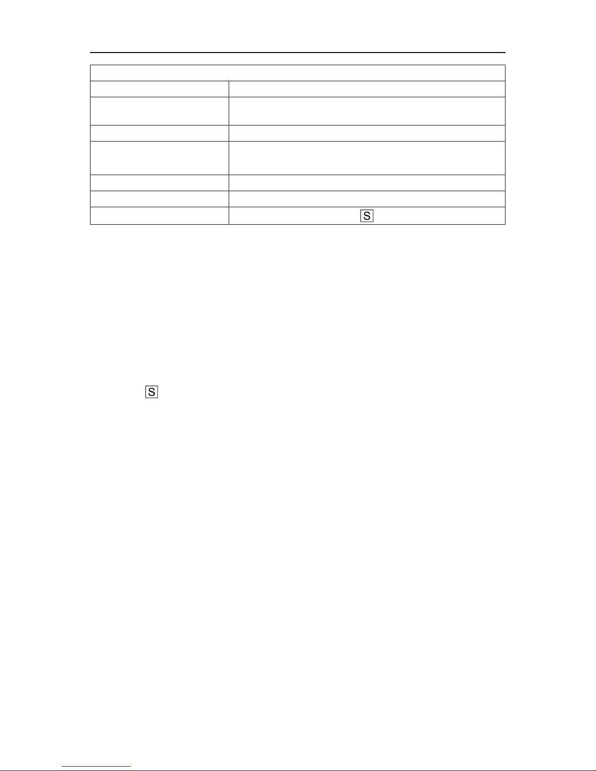
Application class
Mains supply, S
sc min
Minimum short circuit power on the network in accordance with IEC 61000-3-12.
Duty cycle
The duty cycle refers to the time as a percentage of a ten-minute period that you can weld or
cut at a certain load without overloading. The duty cycle is valid for 40°C/104°F, or below.
Enclosure class
The IP code indicates the enclosure class, i.e. the degree of protection against penetration
by solid objects or water.
Equipment marked IP23 is intended for indoor and outdoor use.
Application class
The symbol indicates that the power source is designed for use in areas with increased
electrical hazard.

4 INSTALLATION
0463 416 001
- 11 -
© ESAB AB 2017
4 INSTALLATION
The installation must be carried out by a professional.
CAUTION!
This product is intended for industrial use. In a domestic environment this product
may cause radio interference. It is the user's responsibility to take adequate
precautions.
4.1 Location
Position the power source so that its cooling air inlets and outlets are not obstructed.
A. Minimum 200 mm (8 in.)
B. Minimum 200 mm (8 in.)
WARNING!
Secure the equipment - particularly if
the ground is uneven or sloping.
4.2 Lifting instructions
Mechanical lifting must be done with both outer handles.
4 INSTALLATION
0463 416 001
- 12 -
© ESAB AB 2017
4.3 Mains supply
NOTE!
Mains supply requirements
This equipment complies with IEC 61000-3-12 provided that the short-circuit
power is greater than or equal to S
scmin
at the interface point between the user's
supply and the public system. It is the responsibility of the installer or user of the
equipment to ensure, by consultation with the distribution network operator if
necessary, that the equipment is connected only to a supply with a short-circuit
power greater than or equal to S
scmin
. Refer to the technical data in the
TECHNICAL DATA chapter.
The power source will automatically adjust to the supplied input voltage; make sure it is
protected by the correct fuse rating. A protective earth connection must be made, in
accordance with regulations.
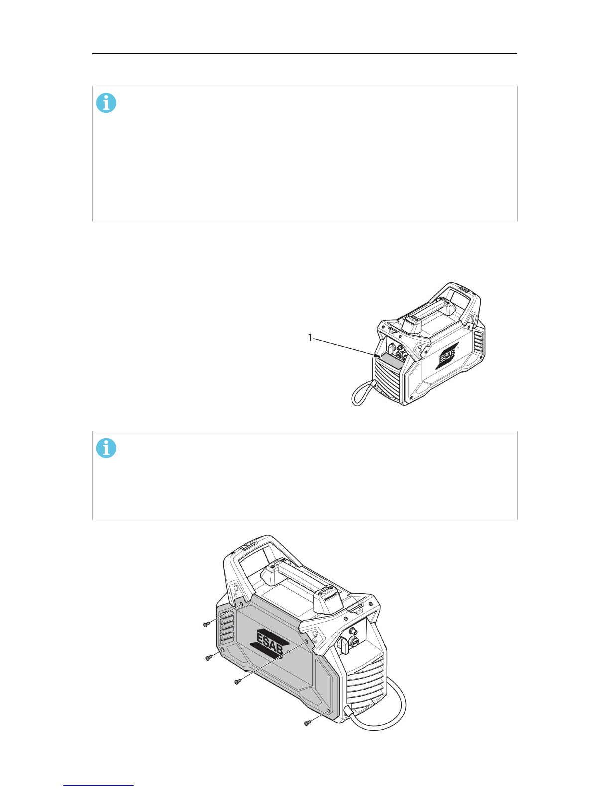
1. Rating plate with supply connection data
Installation of mains cable
NOTE!
The power source is delivered with a 4×2.5mm2mains cable and a 16A mains
plug which in combination can handle the rated data given for 3-phase
380–415V mains supply. If other mains voltage is required, the mains cable may
be changed according to relevant national regulations. For recommendations,
see section Recommended fuse sizes and minimum cable area.

4 INSTALLATION
0463 416 001
- 13 -
© ESAB AB 2017
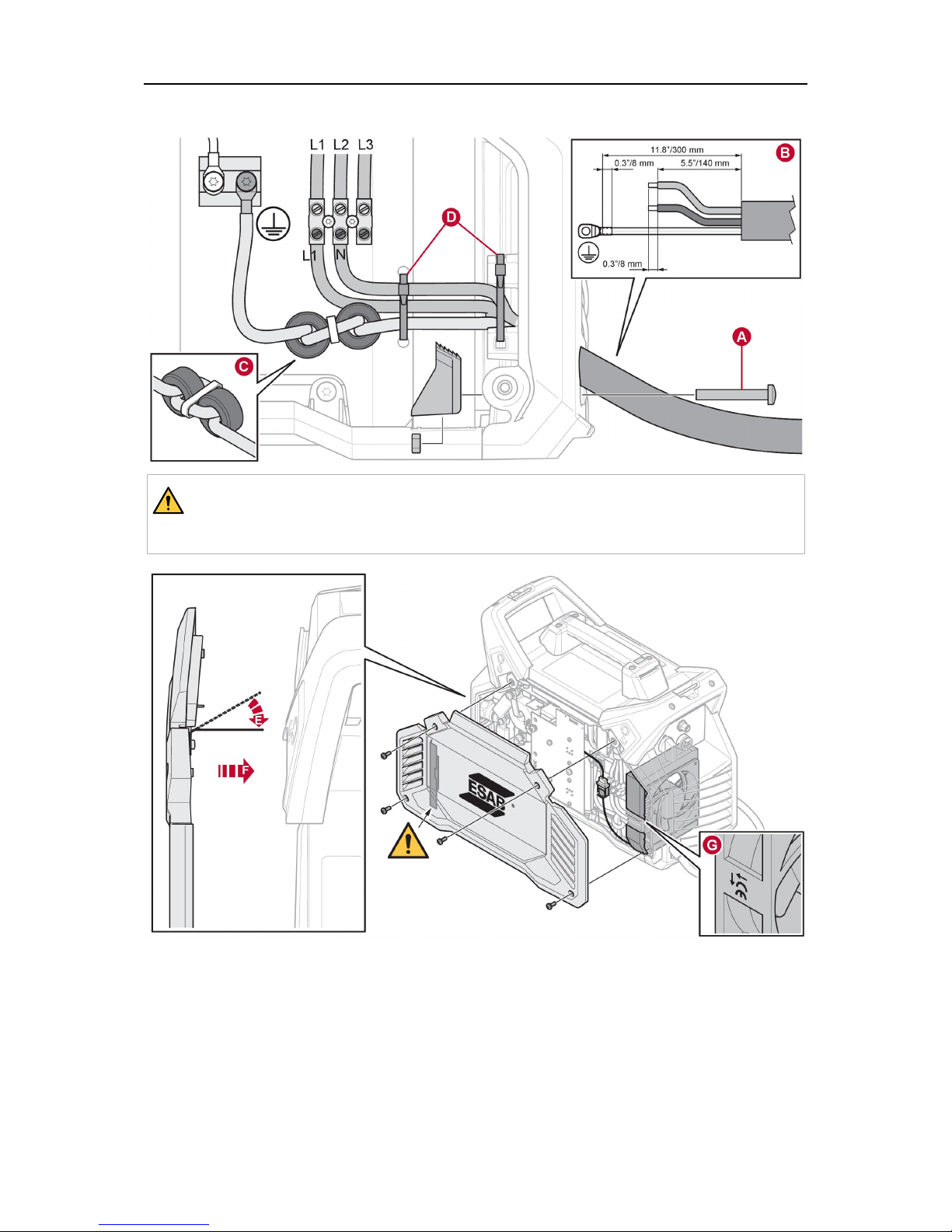
1. Remove the side panel.
2. If tightened, release the stopping block (A).
3. If a cable is connected, disconnect all wires, cut the cable tie (D), and remove the
cable.
4. Optional: The fan with foam can at this point be removed to simplify the installation.
Note the direction of the fan (the sticker towards the inside).
5. Strip the new wire according to specification (B).
6. Insert the cable with about 1 cm (0.4 in.) of isolation inside the stopping block. Tighten
the stopping block by using 1.5–2Nm (13.3–17.7in.lb) (A).
7. Use two cable ties to fasten the cables (D).
8. Optional: If the fan with foam has been removed it shall now be re-installed. A symbol
on the side of the fan (G) shows the air flow direction.
9. Install the ferrites and connect the earth wire (C). A toothed washer should be located
closest to the heat sink. Tighten the screw to a torque of 6.0±0.6Nm (53.1±5.3in.lb).
10. Connect all wires in accordance with illustrations for 1-phase and 3-phase. Tighten the
screw to a torque of 1.0±0.2Nm (8.9±1.8in.lb).
11. Ensure that the IP shield is correctly mounted on the inside of the side panel (E).
12. Reassemble the side panel (F).
13. Tighten the screws on the side panel with 3±0.3Nm (26.6±2.7in.lb).
3-phase
4 INSTALLATION
0463 416 001
- 14 -
© ESAB AB 2017
1-phase
WARNING!
In 1-phase operation the terminal L3 is powered, even though not connected.
Make sure to keep terminal L3 disconnected.
 Loading...