

Page 1
OPERATING INSTRUCTIONS for
F15-110-B
June, 2006
R-36 SERIES
CYLINDER REGULATORS
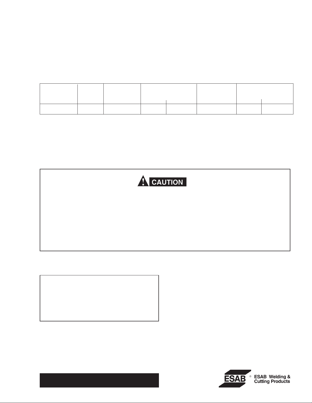
Rated Max.
Regulator Gas Connection, CGA No. Delivery Pressure Gauge, psig
Model P/N Service Inlet Outlet
R-36-500-580 21365 Inert Gas 580 * 400 4000 600
Pressure, psig Cylinder Delivery
CGA-022 (formerly “B” oxygen)—9/16-in.—18 RH male connection.
CGA-023 (formerly ‘‘B” fuel gas)—9/16-in.—18LH male connection.
CGA-032 (formerly ‘‘B” inert gas)—5/8-in.—18RH female connection.
* 1/4-in. 37° Flared Tube Fitting
Inert gas includes nitrogen, argon, and helium.
These INSTRUCTIONS are for experienced operators. If you are not fully familiar with the principles of operation and
safe practices for oxy-fuel gas equipment, we urge you to read our booklet, “Precautions and Safe Practices for Gas
Welding, Cutting, and Heating”, Form 2035. Do NOT permit untrained persons to install, operate, or maintain this
equipment. Do NOT attempt to install or operate this equipment until you have read and fully understand these
lnstructions. lf you do not fully understand these lnstructions,contact your supplier for further information.
The regulators covered by these Instructions are listed by Underwriter’s Laboratories only when using parts
manufactured by ESAB Welding & Cutting Products to the specifications on file with Underwriter’s Laboratories,
Inc., and when they are used in the gas service for which they are designed and listed. The use of other parts that
cause damage or failure to the equipment will void the manufacturer’s warranty.
NOTE: Hoses used with these regulators should have a
working pressure at least equivalent to the maximum gauge reading, with a safety factor of at
least 3 to 1.
IMPORTANT: For packing purposes, the pressure-adjusting screw of the regulator may be
either turned in or packed separately. If installed
in regulator, back out screw (turn counterclockwise) until it turns freely. If packed separately,
install the screw in the regulator cap and turn it in
(clockwise) only one or two turns.
Be sure this information reaches the operator.
You can get extra copies through your supplier.
For Safety Precautions, Installation, &
Operating Instructions, see other side.
Page 2

Safety Precautions
OXYGEN causes many metals and other materials to burn
violently.
INERT GAS OR CARBON DIOXIDE can cause suffocation in
confined spaces.
FUEL GAS can explode in air or oxygen.
z Keep regulator clean and in good repair. Do NOT oil or grease
regulator. Grease and oil on regulator or valve parts can
cause regulator fires.
z Always work in a well-ventilated area.
z Prevent leaks and keep away from heat, flame, and sparks.
z Do not change CGA inlet connection from number stamped
on regulator body.
z Follow Operating Instructions on this sheet.
z This regulator must be installed, operated, and maintained
only by trained servicemen.
z For complete safety information on welding equipment, read
form 2035 (oxy-fuel gas) and 52-529 (electric welding). For
safety information on gases, see your supplier.
INSTALLATION AND OPERATION
TO CONNECT:
1. Open the cylinder or station valve slightly, for an instant. (This is termed ‘cracking the valve’). This will
blow out dust or dirt that may have colIected in the
vaIve outlet. Be sure to keep your face away from the
valve outlet to protect your eyes from dust or dirt.
Never crack a fuel gas valve near sparks, flames or
any other possible source of ignition.
2. Make sure the regulator pressure-adjusting screw is
released by turning it counterclockwise until it turns
freely.
3. Attach the regulator to the valve and tighten the
connection nut with a wrench.
4. Open the cylinder valve slowly. (Open acetylene cylinder valves no more than 1- l/2 turns).
Never stand in front of or behind the rcgulator
when opening the valve. Always stand to one side.
5. Attach the hose to the regulator outlet and to the
equipment with which it is to be used. Tighten the
connecting nuts with a wrench .
IMPORTANT: Before starting operations, test all con-
nections with a Leak Test Solution that is
suitable for oxygen service, such as P/N
998771 (8oz. container). Correct any leaks
before starting work. Testing should be
performed after torch or other gas-using
device has been properly connected and
with maximun delivery pressure in the
delivery line.
TO RELEASE PRESSURE:
If operations are to be stopped for a half-hour or more, you
should release all pressures from regulator. To do this,
proceed as follows:
1. Close the cylinder valve.
2. Open all valves downstream of the regulator.
3. Wait until pressure has dropped to zero, then turn the
pressure-adjusting screw counterclockwise until it turns
freely.
NOTE: If a regulator is to be out of use for a few days or
more, turn in the pressure-adjusting screw enough
to move the valve stem off its seat. When the regulator is returned to use, be sure to back off the
pressure-adjusting screw until it turns freely before
pressure is admitted to the regulator.
MAINTENANCE
INLET FILTER:
Each regulator is equipped with a porous metal inlet filter,
P/N 71Z33, pressed into the regulator inlet nipple. Filters
should be examined each tme a regulator is installed on a
cylinder. Check for; presence, cleanliness and general
appearance. No regulator should be connected to a cylinder or station valve unless it contains this filter. You can
replace the filter if you have reason to do so. To remove a
filter, insert a No. 1 ‘EZY-OUT’ or a No. 6 wood screw
(about 2-in. long) into the filter and pull it out. Press the
new filter into the nipple with a 1 /4-in . round metal rod.
REPAIR SERVICE:
Regulators in need of repair should be returned to your
distributor or to ESAB Remanufacturing Center, Ebenezer Road, Florence, SC.
TO ADJUST PRESSURE:
1. To increase delivery pressure, turn the pressure adjusting screw clockwise. To decrease delivery pressure,
turn the pressure-adjusting screw counterclockwise.
2. When making the initial delivery pressure adjustment,
all valves downstream of the regulator must be open or
you will not get a true working-pressure reading on the
delivery-pressure gauge.
F15-110-B 06 / 2006 Printed inU S.A.
NOTE: Safety release device equipped on oxygen and inert
gas regulators is designed for regulator protection;
not for hose or equipment downstream. If gas
escapes through the safety release device, immediately close cylinder valve and then remove regulator from service for repair.
 Loading...