

Page 1

GB
Valid for serial no. 145-xxx-xxxx0463 277 001 GB 20121125
PowerCut™ 400
PT-39
Instruction manual
Page 2

- 2 -
Page 3

- 3 -
Page 4

- 4 -
Page 5

- 5 -
TOCe
Rights reserved to alter specifications without notice.
APPLICATIONS 24.......................................................
1 SAFETY 6...........................................................
2 INTRODUCTION 8...................................................
2.1 Equipment 8................................................................
3 TECHNICAL DATA 8.................................................
4 INSTALLATION 9....................................................
4.1 Delivery check and location 10.................................................
4.2 Primary power supply 11......................................................
4.3 Input air connection 12........................................................
4.4 Connection for return cable 12.................................................
4.5 Connection of torch 13........................................................
5 OPERATION 14.......................................................
5.1 Connections 14..............................................................
5.2 Control devices 15...........................................................
5.2.1 Symbol key 16..........................................................
5.3 Installing consumables for the torch 17..........................................
5.4 Cutting 18...................................................................
6 MAINTENANCE 19....................................................
6.1 Inspection and cleaning 20....................................................
7 TROUBLESHOOTING 20..............................................
7.1 Troubleshooting guide 21......................................................
8 ORDERING SPARE PARTS 23.........................................
DIAGRAM 24............................................................
WEAR PARTS 27........................................................
ORDER NUMBER 28.....................................................
Page 6

© ESAB AB 2012
- 6 -
bp28e
1 SAFETY
Users of ESAB equipment have the ultimate responsibility for ensuring that anyone who works on or
near the equipment observes all the relevant safety precautions. Safety precautions must meet the
requirements that apply to this type of equipment. The following recommendations should be
observed in addition to the standard regulations that apply to the workplace.
All work must be carried out by trained personnel well-acquainted with the operation of the
equipment. Incorrect operation of the equipment may lead to hazardous situations which can result
in injury to the operator and damage to the equipment.
1. Anyone who uses the equipment must be familiar with:
S its operation
S location of emergency stops
S its function
S relevant safety precautions
S welding and cutting
2. The operator must ensure that:
S no unauthorised person is stationed within the working area of the equipment when it is
started up.
S no-one is unprotected when the arc is struck
3. The workplace must:
S be suitable for the purpose
S be free from drafts
4. Personal safety equipment
S Always wear recommended personal safety equipment, such as safety glasses, flame-proof
clothing, safety gloves.
S Do not wear loose-fitting items, such as scarves, bracelets, rings, etc., which could become
trapped or cause burns.
5. General precautions
S Make sure the return cable is connected securely.
S Work on high voltage equipment may only be carried out by a qualified electrician.
S Appropriate fire extinquishing equipment must be clearly marked and close at hand.
S Lubrication and maintenance must not be carried out on the equipment during operation.
GB
Page 7

© ESAB AB 2012
- 7 -
bp28e
WARNING
Read and understand the instruction manual before installing or operating.
Arc welding and cutting can be injurious to yourself and others. Take precautions when welding and
cutting. Ask for your employer's safety practices which should be based on manufacturers' hazard
data.
ELECTRIC SHOCK - Can kill
S Install and earth the unit in accordance with applicable standards.
S Do not touch live electrical parts or electrodes with bare skin, wet gloves or wet clothing.
S Insulate yourself from earth and the workpiece.
S Ensure your working stance is safe.
FUMES AND GASES - Can be dangerous to health
S Keep your head out of the fumes.
S Use ventilation, extraction at the arc, or both, to take fumes and gases away from your breathing zone
and the general area.
ARC RAYS - Can injure eyes and burn skin.
S Protect your eyes and body. Use the correct welding screen and filter lens and wear protective
clothing.
S Protect bystanders with suitable screens or curtains.
FIRE HAZARD
S Sparks (spatter) can cause fire. Make sure therefore that there are no inflammable materials nearby.
NOISE - Excessive noise can damage hearing
S Protect your ears. Use earmuffs or other hearing protection.
S Warn bystanders of the risk.
MALFUNCTION - Call for expert assistance in the event of malfunction.
PROTECT YOURSELF AND OTHERS!
WARNING
Do not use the power source for thawing frozen pipes.
CAUTION
Class A equipment is not intended for use in residential locations where
the electrical power is provided by the public low-voltage supply system.
There may be potential difficulties in ensuring electromagnetic
compatibility of class A equipment in those locations, due to conducted
as well as radiated disturbances.
CAUTION
This product is solely intended for plasma cutting.
CAUTION
Read and understand the instruction manual before
installing or operating.
GB
Page 8

© ESAB AB 2012
- 8 -
bp28e
Dispose of electronic equipment at the recycling facility!
In observance of European Directive 2002/96/EC on Waste Electrical and Electronic
Equipment and its implementation in accordance with national law, electrical and/or
electronic equipment that has reached the end of its life must be disposed of at a
recycling facility.
As the person responsible for the equipment, it is your responsibility to obtain
information on approved collection stations.
For further information contact the nearest ESAB dealer.
ESAB can provide you with all necessary cutting protection and accessories.
2 INTRODUCTION
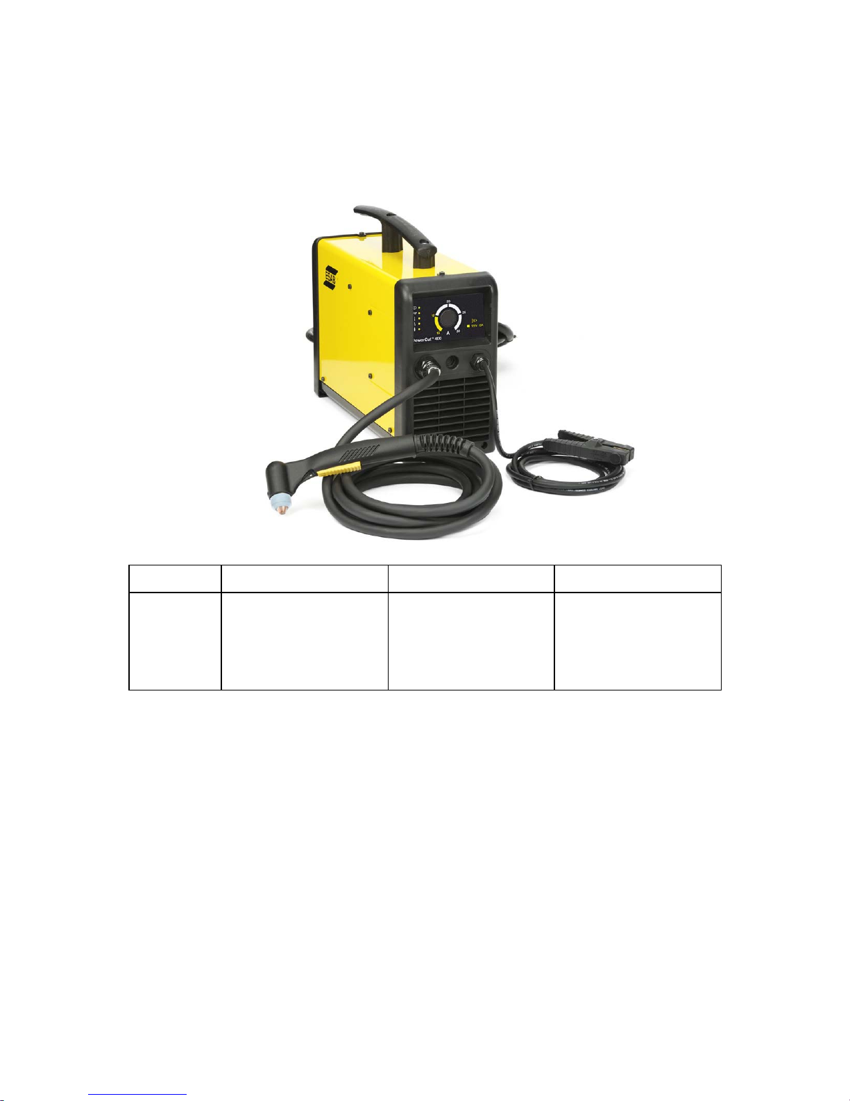
The PowerCut 400 is a complete system for manual plasma cutting. It delivers
cutting power for severing materials up to 13 mm thickness.
2.1 Equipment
The power source is supplied with:
S power cable, 3 m
S instruction manual
S return cable with clamp
S plasma cutting torch PT-39, 4.6 m, supplied as indicated on page 28
S wear part kit for PT-39.
3 TECHNICAL DATA
PowerCut 400
Mains voltage range 90 - 280 V , 1 ~, 50/60 Hz
Setting range, rated value 110 V: 15 – 25 A
230 V: 15 – 30 A
Permitted load
25 % duty cycle 110 V
60 % duty cycle 110 V
20 % duty cycle 230V
60 % duty cycle 230 V
25 A
19 A
30 A
18 A
Power factor at maximum current 0.99
Efficiency at maximum current 75 %
Open-circuit voltage U
0
250 V
Operating temperature -10 to 40 °C
Transportation temperature -20 to 55 °C
Sound pressure at no load < 43 db (A)
Nominal flow rate 189 l/min at 4.8 bar
Dimensions, l x w x h 465 x 160 x 340 mm
Weight including torch and return cable 14.5 kg
Insulation class transformer H
Enclosure class IP 23
GB
Page 9

© ESAB AB 2012
- 9 -
bp28e
Duty cycle
The duty cycle refers to the time as a percentage of a ten-minute period that you can weld or cut at
a certain load without overloading. The duty cycle is valid for 40°C.
Enclosure class
The IP code indicates the enclosure class, i. e. the degree of protection against penetration by solid
objects or water. Equipment marked IP23 is designed for indoor and outdoor use.
4 INSTALLATION
The installation must be carried out by a professional.
Correct installation is very important for trouble-free operation and good cutting
results. Carefully read and follow each step in this chapter.
WARNING
ELECTRIC SHOCKS CAN KILL Take precautionary measures against electric
shocks. Ensure that all power supplies are disconnected – switch off the switch at
the wall socket and pull out the equipment's power cable from the socket before
making any electrical connections in the power source.
WARNING
It is very important that the chassis is connected to the approved electric protective
earth, to prevent electric shocks and electrical accidents. Ensure that protective
earth is not connected to any phase conductors by mistake.
WARNING
Poor connections or failure to connect the return cable to the workpiece can result
in fatal electric shock.
WARNING
Air filter devices may not be used – installation or mounting of any form of air filter
device obstructs the cold air flow and causes a risk of overheating. The warranty is
invalidated if any type of air filter is used.
GB
Page 10
© ESAB AB 2012
- 10 -
bp28e
WARNING
Do NOT start the equipment with the cover removed.
Do NOT connect the power source with the main switch in ON position or when you
are holding it or carrying it.
Do NOT touch any of the torch's parts when the power supply is on.
CAUTION
This product is intended for industrial use. In a domestic environment this product may
cause radio interference. It is the user's responsibility to take adequate precautions.
CAUTION
Place the power source at least 3 metres from the cutting area as sparks and slag spray
can damage the power source
4.1 Delivery check and location
1. Remove the packaging. Inspect the equipment for damage that was not
immediately apparent upon reception of the delivery. Immediately report any
damage to the delivery company.
2. Check for any loose parts in the packaging. Check that the air ducts in the
cover's rear panel are not blocked by packaging material that can prevent the air
flow through the power source.
The power source has a carrying handle and can be lifted easily.
3. Position the power source so that its cooling air inlets and outlets are not
obstructed. Minimum permitted distance to wall or other obstruction is
1 m.
4. An air source that gives clean and dry air, at least 189 l/m at 4.8 bar, is
required for cutting. The cutting air pressure must not exceed 6 bar, which is the
maximum inlet pressure for the filter regulator that is included in the delivery.
GB
Page 11
© ESAB AB 2012
- 11 -
bp28e
4.2 Primary power supply
Make sure that the power source is connected to the correct supply voltage and that
it is protected by the correct fuse rating. A protective earth connection must be made
in accordance with regulations.
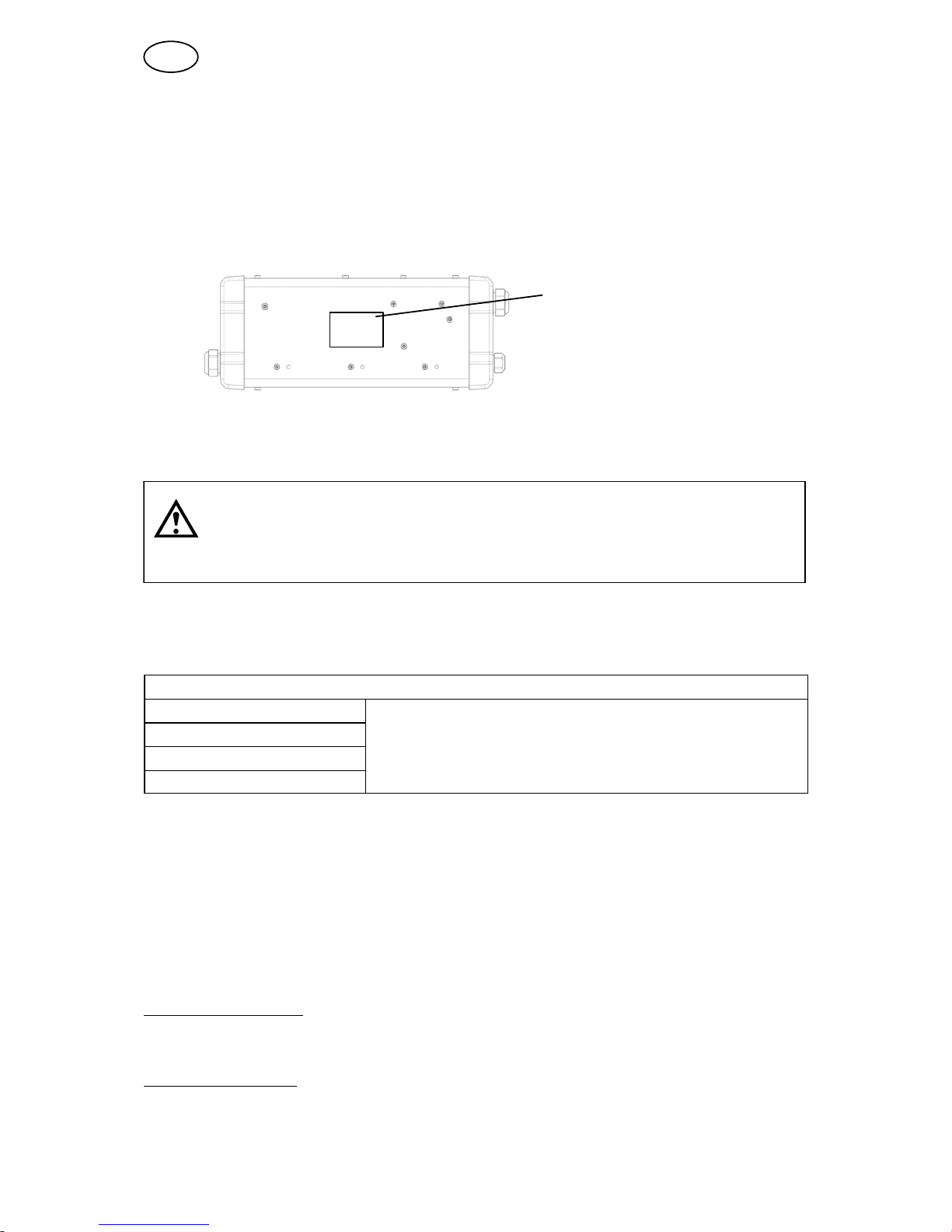
Rating plate with supply
connection data
WARNING
Make sure the power source is switched off before removing the fuse.
Recommended fuse sizes and minimum cable area
Powercut 400
Mains voltage 110 V 1~ 230 V 1~
Mains cable area
3G2.5 3G2.5
Phase current I
1eff
16 A 9 A
Fuse, anti-surge 32 A 16 A
NOTE! The mains cable areas and fuse sizes as shown above are in accordance with Swedish
regulations. Use the power source in accordance with the relevant national regulations.
Supply from power generators
The power source can be supplied from different types of generators. However,
some generators may not provide sufficient power for cutting. Generators with AVR,
equivalent or better type of regulation with a min rated power of 6 kW are
recommended to supply the power source within it's full capacity.
Start with generator:
1) Start the generator
2) Turn on the power source by mains switch ON
Stop with generator
3) Turn off the power source by mains switch OFF
4) Stop the generator
GB
Page 12
© ESAB AB 2012
- 12 -
bp28e
4.3 Input air connection
Connect your air supply to the inlet connection of the filter. Any cylinder of
compressed air or air from a compressor may be used. The air must be free from
polluting particles. A pressure regulator is provided to ensure the correct air flow rate
on the torch. It is set from factory at 4.8 bar.
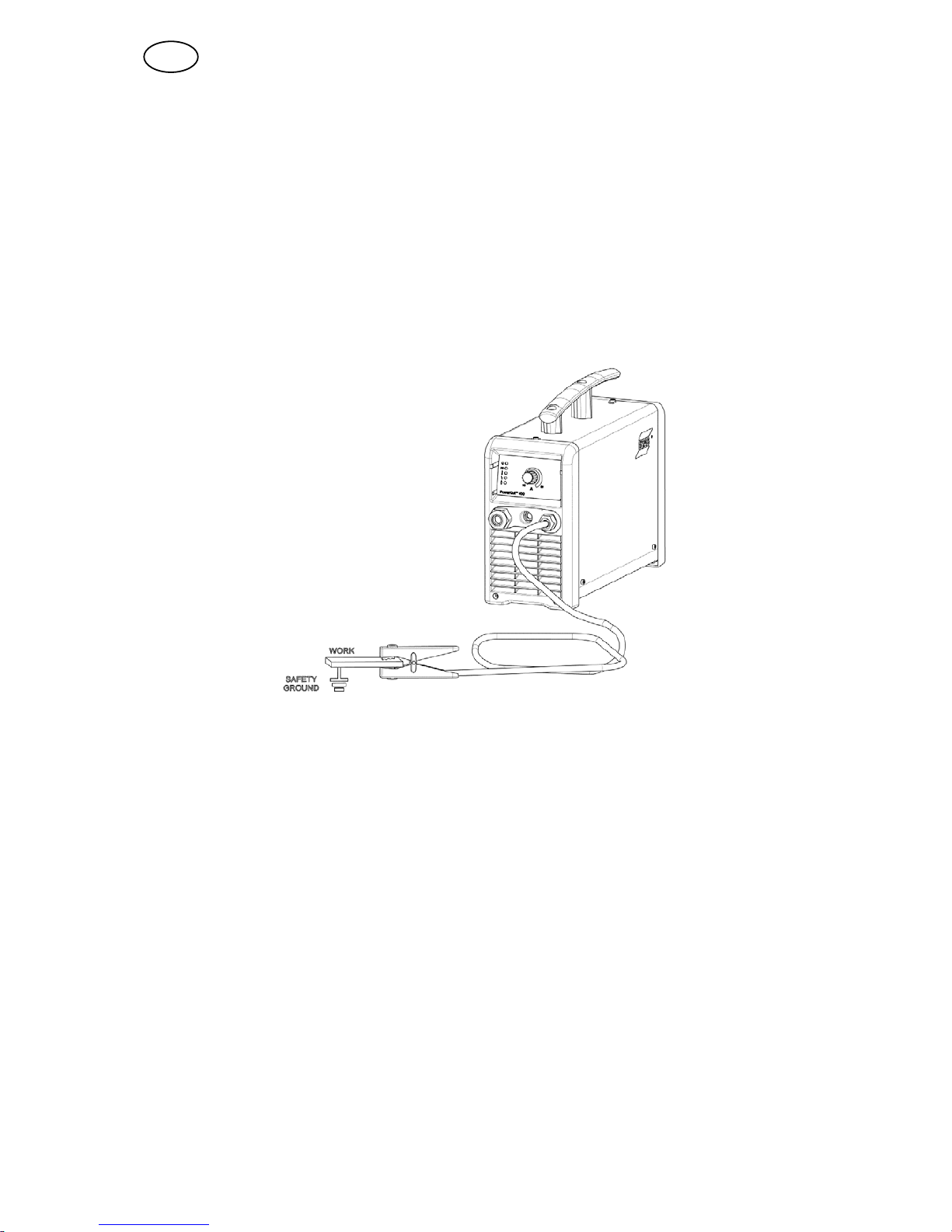
4.4 Connection for return cable
Clamp the return cable to the workpiece. Be sure the workpiece is connected to an
approved earth ground with a properly sized ground cable.
GB
Page 13
© ESAB AB 2012
- 13 -
bp28e
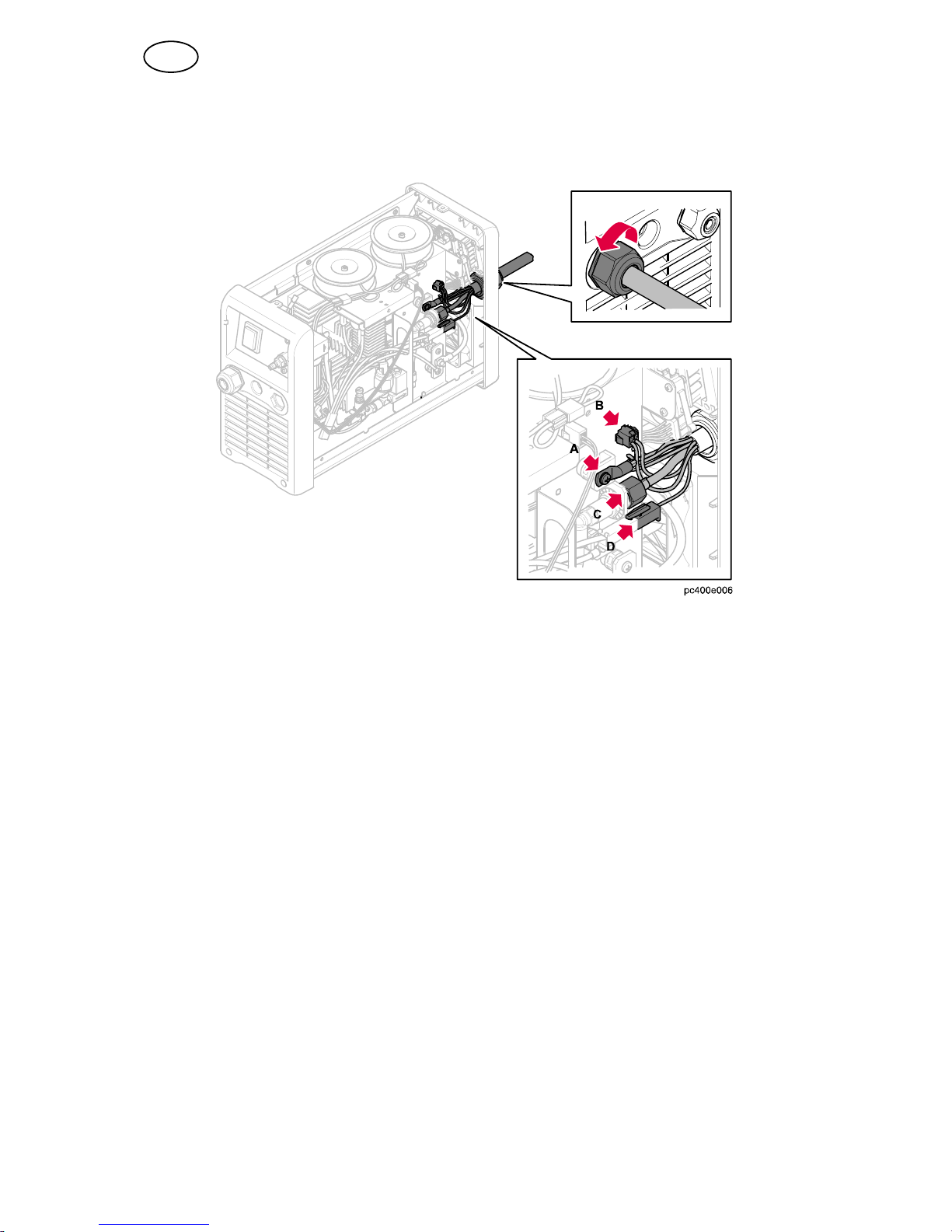
4.5 Connection of torch
The installation must be carried out by a professional.
A Torch power cable, violet
B Torch trigger cables, black
C Air hose to quick-connect fitting
D Torch pilot cable, red
The power source is equipped with a quick-disconnect solution for connecting and
disconnecting the torch.
1. Turn off the main switch, disconnect the power cable and the air supply.
2. Open the little left side panel by unscrewing 2 screws.
3. Insert the torch end with cable receptacle and air hose through the hole in the
front of the power source.
4. Connect the violet torch power cable by tightening 1 screw.
5. Connect the 2 black torch trigger cables.
6. Connect the red torch pilot cable.
7. Connect the air hose to the fitting.
8. Close the little left side panel.
9. Connect the power cable and turn on the main switch.
GB
Page 14
© ESAB AB 2012
- 14 -
bp28e
5 OPERATION
General safety regulations for handling the equipment can be found on
page 6. Read through before you start using the equipment!
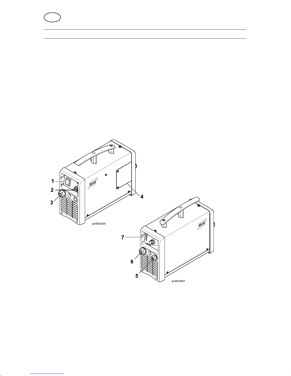
5.1 Connections
1 Power switch ON/OFF 5 Connection for return cable
2 Connection for air 6 Connection for torch
3 Power cable 7 Control devices, see chapter 5.2
4 Side panel
GB
Page 15
© ESAB AB 2012
- 15 -
bp28e
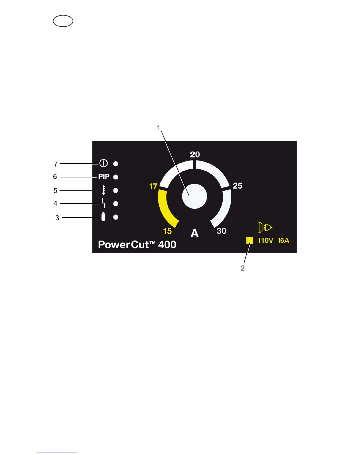
5.2 Control devices
1 Knob for setting of current 5 Over temperature indicator, yellow
2 Primary input voltage/Circuit breaker key 6 Parts In Place (PIP), yellow
3 Air pressure indicator, yellow 7 Power ON indicator, green
4 Fault indicator, yellow
1 Output current control
Output current control can vary the cutting current from 15A to 30A. Adjusting the
current will affect the power consumed by the machine, the thickness of material that
can be cut, and the quality of a cut at a given speed. Special care should be taken to
keep the cutting current below 17A when powering the machine from 110V mains
supply with a 16A circuit breaker.
2 Primary Input Voltage/Circuit Breaker Key
The symbol explains the yellow field on the output current control. Max output
current for 110 V and 32A circuit breaker is 25A.
3 Air Pressure Indicator
The yellow LED indicates that the air pressure is too low.
4 Fault Indicator
The flashing yellow LED indicates that the safety switch for the cover is activated
and the power is automatically turned off.
GB
Page 16
© ESAB AB 2012
- 16 -
bp28e
5 Over Temperature Indicator
When the yellow LED is lit, the working temperature has exceeded the normal
values. It is turned off when the temperature is normal.
6 Parts in Place (PIP)
When the yellow LED is lit, it indicates that there is a parts-in-place error. This
means that no nozzle was detected, or that the electrode is not retracting properly.
Turn off the power. Check that the components are properly assembled, that they
are free from excessive damage, and that the electrode can slide back and forth with
comfortable pressure from one finger. Once the source of the error has been
corrected, turn on the power again.
7 Power ON Indicator
When the green LED is lit, it indicates that the power is on.
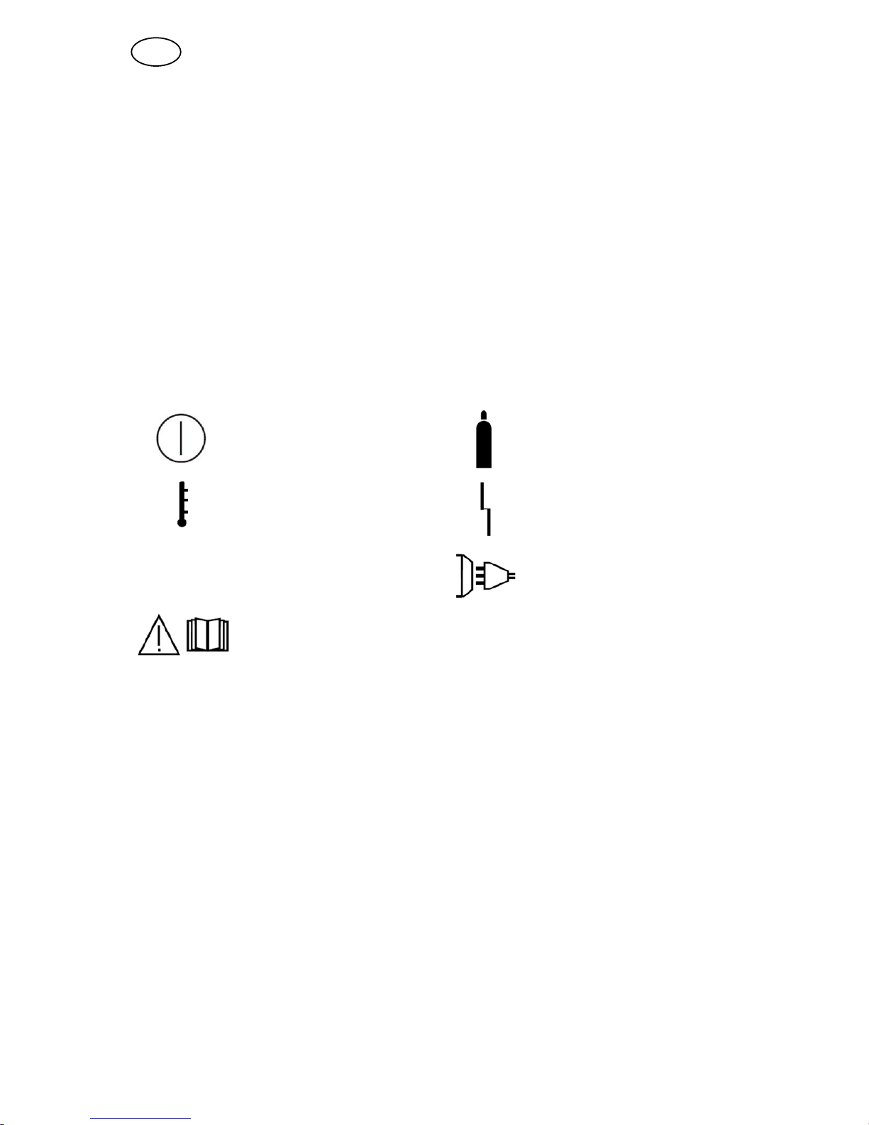
5.2.1 Symbol key
Power Air
Temperature Fault
PIP
Parts in Place Power supply
Read the manual
GB
Page 17
© ESAB AB 2012
- 17 -
bp28e
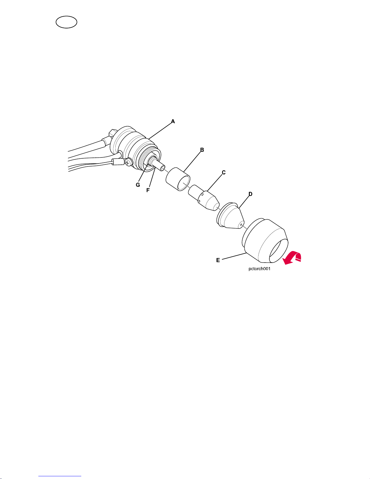
5.3 Installing consumables for the torch
Proper use of the torch within rated operating conditions (especially arc current and
gas flow rate) and correct installation of consumable parts can prevent unnecessary
torch damage.
1. Tighten electrode and retaining/shield cup fully at each consumable change or
inspection.
2. Check consumable tightness at the beginning of each work period, even if
everything was working normally at the end of the previous period.
A Torch body assembly
B Baffle
C Electrode
D Nozzle
E Retaining/Shield cup
F Piston
G Electrode/Torch body seat
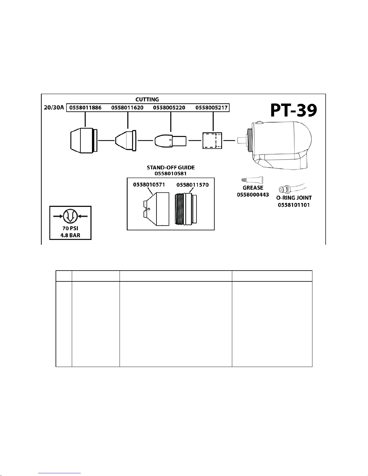
See wear parts on page 27.
GB
Page 18
© ESAB AB 2012
- 18 -
bp28e
5.4 Cutting
1. Set the switch (wall socket or similar) to on.
2. Check that the compressor is connected to the power source.
3. Set the power switch to I (On).
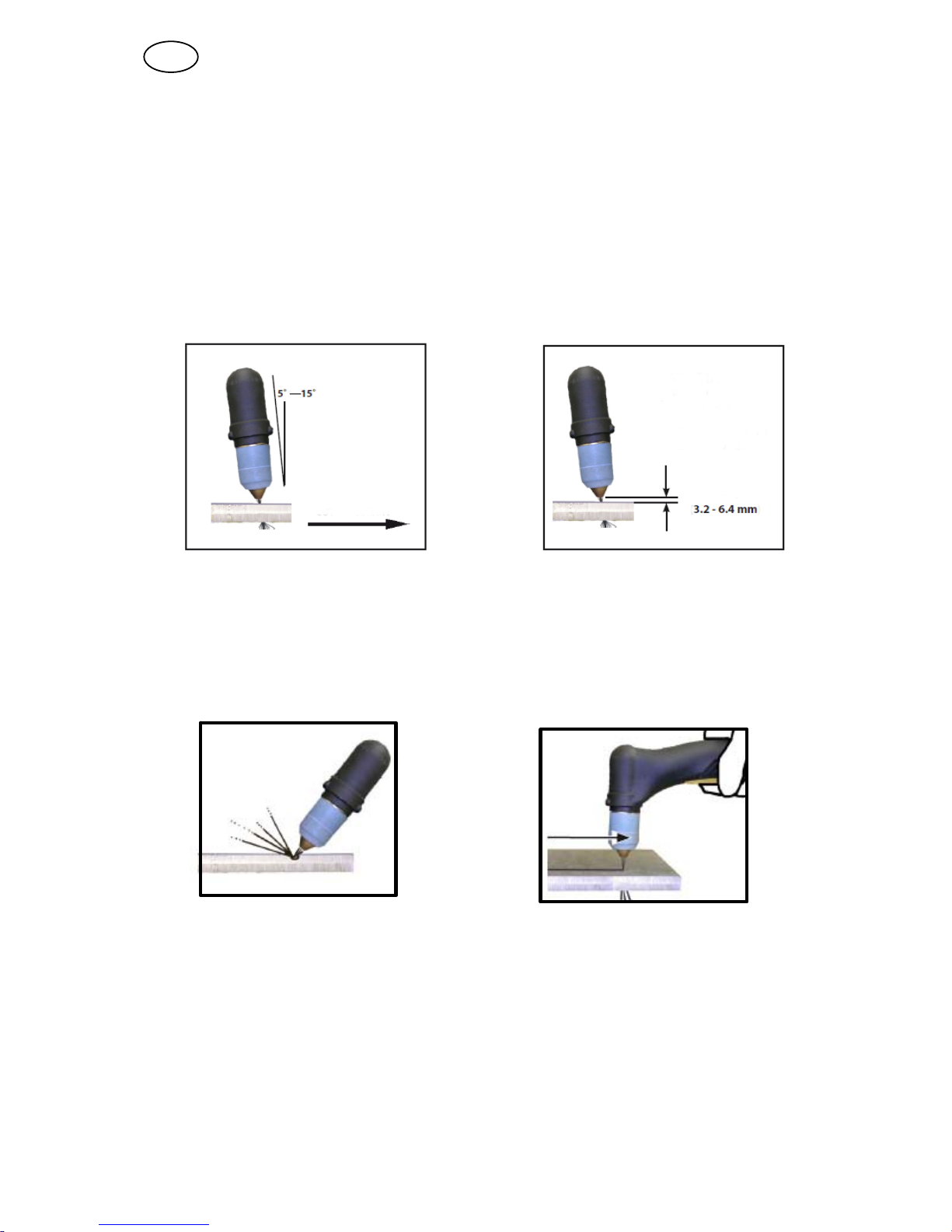
4. After starting the cut, the torch should be maintained at a 5 - 15° forward angle.
This angle is especially useful in helping to create a “drop” cut. The torch can be
operated with the nozzle dragging on the plate or with up to 6.35 mm standoff.
The ideal standoff is 3.2 mm. Standoff guides are available to simplify
maintaining the gap, see wear parts on page 27.
5. Depress the torch switch. Air should flow from the torch nozzle.
6. Two seconds after depressing the torch switch, the pilot arc should start. The
main arc should immediately follow, allowing the cut to begin.
7. To start a cut, tilt the torch to prevent molten material from splashing back and
damaging the torch. When the arc breaks through the workpiece, bring the torch
to an upright position and proceed to cut.
8. When ending a cut, the torch switch should be released and the torch lifted off
the workpiece immediately upon completion of the cut. This is to prevent the pilot
arc from re-igniting after the cutting arc has extinguished and causing damage to
the nozzle (double arcing).
9. For rapid re-starts on machines that support grate cutting mode, do not release
the torch switch. The torch will automatically return to pilot arc mode after each
cut and transfer back to main arc, when the torch is positioned over the next
working surface. When working without grate cutting mode, simply release and
re-press the trigger during the postflow to restart the arc without a delay for
preflow.
GB
Page 19
© ESAB AB 2012
- 19 -
bp28e
Speed
Typically, manual plasma cutting speeds are limited by the sever speed. This
indicates the maximum speed you will be able to move the torch along the cut while
still penetrating the work piece. However, for applications that require a cleaner cut,
it may be important to cut closer to the quality speed.
If the cut is made too quickly, significant quantities of molten metal can form dross on
the underside of the cut. While most slag formed from carbon steel will easily chip
off, it can be a nuisance. Quality speeds are selected to keep dross formation to a
minimum.
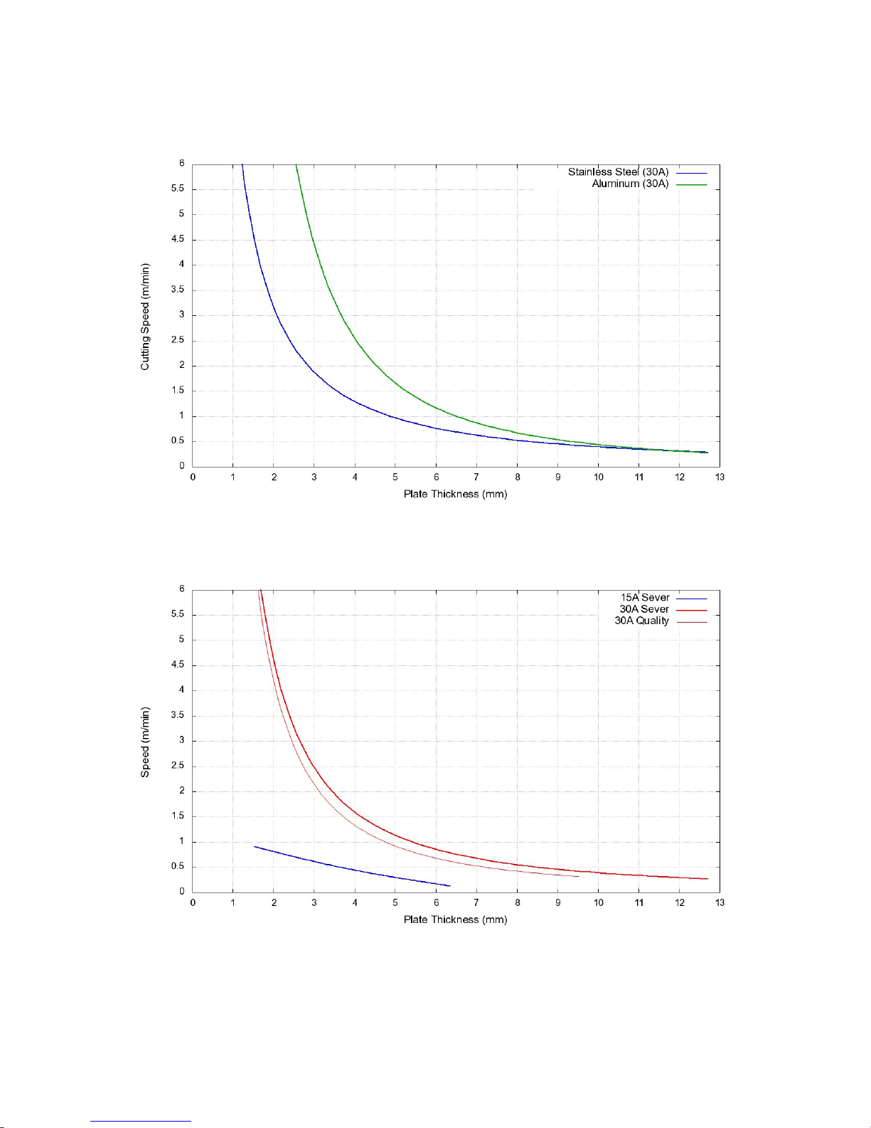
On page 26 data shows the maximum cutting speeds possible for the power source
at 15 - 30A. Quality cut speed recommendations are also listed for steel.
Note that when the torch is used at its limits, the quality of the cut suffers.
6 MAINTENANCE
Regular maintenance is important to get the optimal performance and lifetime.
Only those persons who have appropriate electrical knowledge (authorized
personnel) may remove the safety plates.
WARNING
Ensure that the mains voltage supply to the power source has been disconnected
externally. Switch off the switch at the wall socket before inspecting or working in
the power source.
WARNING
Water or oil can collect in the compressed air lines. Always direct the first stream of
air away from the equipment, to prevent damage.
CAUTION
All guarantee undertakings from the supplier cease to apply if the customer attempts any
work to rectify any faults in the product during the guarantee period.
If the equipment does not work correctly, stop work immediately and determine the
cause of the problem. Maintenance work may only be carried out by persons with
the applicable knowledge. Electrical work may only be carried out by authorised
electricians. Never allow persons other than those with the applicable knowledge to
check, clean or repair the equipment. Use only ESAB original spare and wear parts.
GB
Page 20
© ESAB AB 2012
- 20 -
bp28e
6.1 Inspection and cleaning
The following points on the power source should be checked and/or cleaned
regularly.
1. Check the return cable connection to the work piece.
2. Check that the protective earth from the work piece is securely connected to the
power source chassis earth.
3. Check the torch heat shield. Replace it if it is damaged.
4. Check the electrode and the nozzle for wear daily. Remove any splash, replace
the electrode and nozzle as necessary. If the electrode has pitting which is more
than 3.2 mm deep at its centre, it must be replaced. If the electrode is used
beyond this recommended wear limit, damage to the torch and power source
may occur. Nozzle life is also greatly reduced when using the electrode below
the recommended limit.
5. Check that the cables or hoses are not damaged or bent.
6. Check that all plugs and connections and ground terminals are firmly connected.
7. Ensure that all incoming power supplies are disconnected. Use goggles and face
mask and blow clean the power source internally using dry compressed air at
low pressure .
7 TROUBLESHOOTING
WARNING
ELECTRIC SHOCKS CAN KILL! Ensure that the mains voltage supply to the power
source has been disconnected externally. Switch off the switch at the mains
socket before inspecting or working in the power source.
WARNING
Plasma cutting equipment uses extremely high voltages that can cause severe
injury or even death. Observe extreme caution when working with the covers
removed.
Try these recommended checks and inspections before sending for an authorized
service technician.
Type of fault Corrective action
Insufficient penetration S Current too low
S Cutting speed too fast
S Damaged cutting nozzle
S Improper air pressure
S Low air flow rate
Main arc extinguishes. S Cutting speed too slow
S Worn electrode
GB
Page 21

© ESAB AB 2012
- 21 -
bp28e
Type of fault Corrective action
Dross formation (In some materials and
thicknesses it may be impossible to get
dross-free cuts.)
S Current too low
S Cutting speed too fast or too slow
S Improper air pressure
S Faulty nozzle or electrode
S Low air flow rate
Double arcing (Damaged nozzle orifice) S Low air pressure
S Damaged cutting nozzle
S Loose cutting nozzle
S Heavy spatter accumulation on nozzle
Uneven arc S Damaged cutting nozzle or worn electrode
Unstable cutting conditions S Incorrect cutting speed
S Loose cable or hose connections
S Electrode and/or cutting nozzle in poor
condition
Main arc does not strike. S Worn electrode
S Loose connections
S Work cable not attached
Poor consumable life S Improper gas pressure
S Contaminated air supply
S Low air flow rate
7.1 Troubleshooting guide
Problem Cause Solution
The ON/OFF switch is in
position 1, but the green LED
(power) does not light up.
S There is no power present.
S Tripped circuit breaker
S Check the power supply.
S Check the breaker.
The power source is on, but the
yellow AIR PRESSURE LED
remains lit.
S The air pressure is low.
S No air is present
S Check that the air filter is
not blocked.
S Increase the air pressure.
S Check if air is supplied.
The power source is on, but the
yellow OVER TEMPERATURE
LED remains lit.
S The power source is still
overheated. It will cool
down sooner with the fan
on.
S The thermal switch is
faulty.
S Switch on the power
source and wait a few
minutes before working
again.
S Call authorized service
technicians.
The power source is on, the
orange FAULT LED remains lit.
S The power source is not
enabled. A safety switch,
cover, has been activated.
S Check if the consumables
are in place and properly
tightened.
S Check that the side panel
has been correctly closed
(torch connector inspection
side).
The power source is on, the
yellow PIP LED remains lit.
S There is a parts-in-place
error.
S Check if the consumables
are in place and properly
tightened.
GB
Page 22

© ESAB AB 2012
- 22 -
bp28e
Problem SolutionCause
The thermal switch trips during
cutting.
S The power required by the
power source has
exceeded the power
available from the incoming
line voltage.
S Another appliance is
working on the same line.
S Reduce the cutting current
with the command on the
front panel or reduce the
cutting time.
S Reduce the length of the
connecting cable or
increase the cable section.
S Do not connect other
appliances to the same
line.
The arc does not strike or the
arc disappears during cutting.
S The wear parts of the torch
are worn.
S The generator is
overheated.
S There is not sufficient air
pressure.
S There is low voltage on the
incoming line.
S Check the torch and fit
spare parts if necessary.
S See if the yellow OVER
TEMPERATURE LED on
the front panel is lit. Wait
until the power source
cools down.
S See if the yellow AIR
PRESSURE LED on the
front panel is lit. Increase
the air pressure.
S Check whether the air filter
is blocked and replace it if
necessary.
S Check the incoming line. If
an extension is being used,
ensure that the cable
section is adequate.
The pilot is working but there is
not sufficient current for cutting.
S Bad contact of the earth
clamp
S Bad connection of the
positive pole at the torch
cable
S Check that the earth clamp
has a good contact with
the piece to be cut.
S Check the connection of
the positive pole at output
to the socket, even on the
inside.
The cut is not perpendicular. S Worn electrode or nozzle S Replace the electrode and
the nozzle.
GB
Page 23
© ESAB AB 2012
- 23 -
bp28e
8 ORDERING SPARE PARTS
Repair and electrical work should be performed by an authorised ESAB service
technician. Use only ESAB original spare and wear parts.
PowerCut 400 is designed and tested in accordance with the international and European
standards EN 60974-1, EN 60974-10. It is the obligation of the service unit which has carried
out the service or repair work to make sure that the product still conforms to the said stan
dard.
PT-39 is designed and tested in accordance with the international and European standard EN
60974-7. It is the obligation of the service unit which has carried out the service or repair work to
make sure that the product still conforms to the said standard.
Spare parts may be ordered through your nearest ESAB dealer, see the last page of
this publication.
GB
Page 24
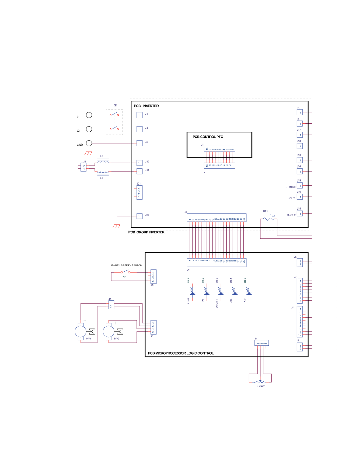
© ESAB AB 2012
Diagram
- 24 -
bp28diag
Page 25
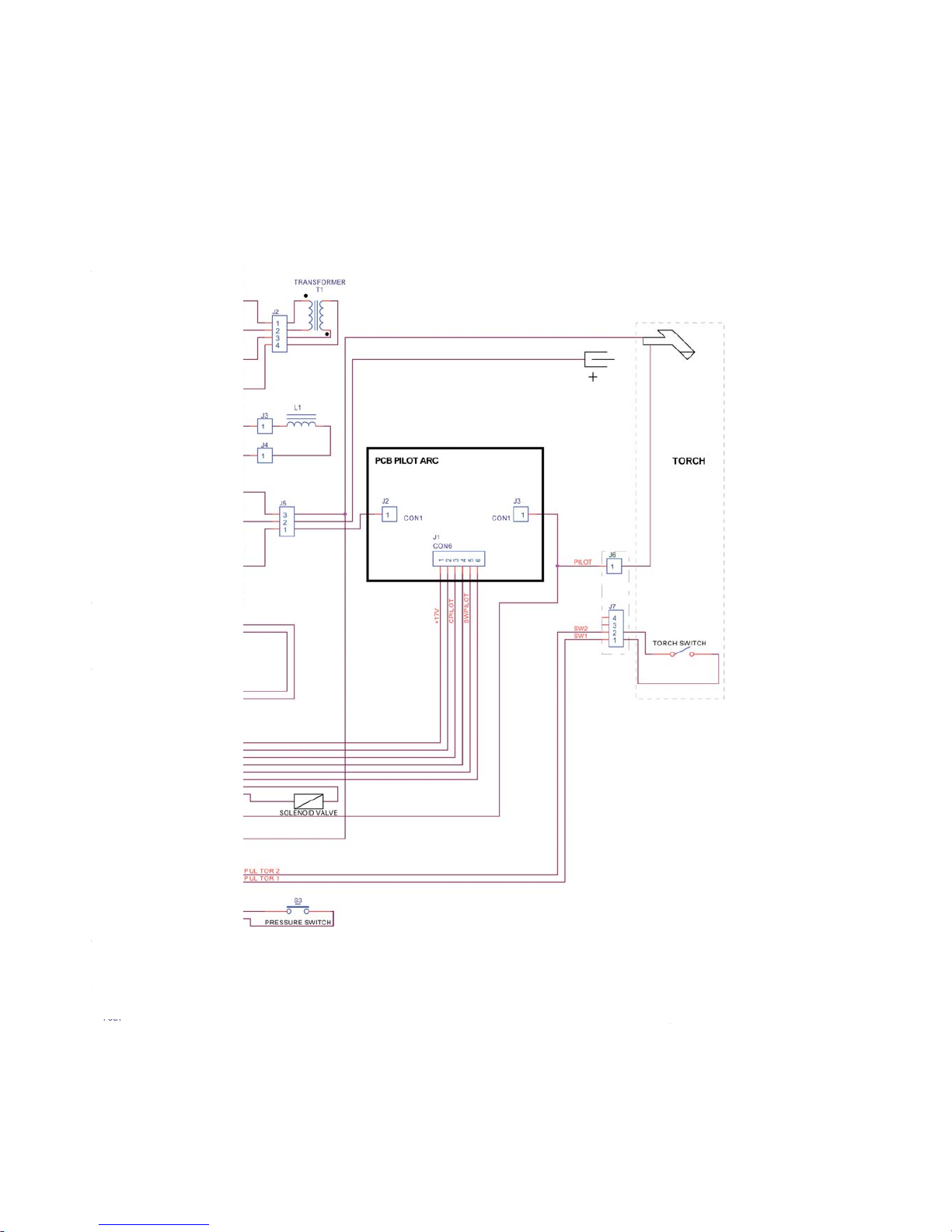
© ESAB AB 2012
- 25 -
bp28diag
Page 26
© ESAB AB 2012
- 26 -
bp28app2
Stainless Steel and Aluminium Cut Speeds
Carbon Steel Cut Speeds
Page 27
PowerCut™ 400 PT-39
© ESAB AB 2012
Wear parts
- 27 -
bp28wear
Wear parts
Wear parts kit PT-39
Qty Ordering no. Denomination Notes
0558 010 586 Wear parts kit consisting of: 30 Amp for PowerCut 400
3 0558 005 220 Electrode
1 0558 005 217 Gas baffle 30 - 80 Amp
4 0558 011 620 Nozzle 30 Amp
1 0558 011 886 Retaining cup
1 0558 010 581 Standoff guide assy
3
O-ring .301ID .070W Nitrile
1
Grease silicon dow DC-111 (1/4 Oz)
Page 28
PowerCut™ 400 PT-39
© ESAB AB 2012
Order number
- 28 -
bp28o
Ordering no. Denomination Type Notes
0700 210 880 Power source for plasma
cutting incl torch (4.6m),
return cable and wear part
kit
PowerCut™ 400 90V-280V,1-ph
0558 010 576 Torch PT-39 4.6 m
Technical documentation is available on the Internet at www.esab.com
Page 29

- 29 -
notes
NOTES
.............................................................................................................................................................
.............................................................................................................................................................
.............................................................................................................................................................
.............................................................................................................................................................
.............................................................................................................................................................
.............................................................................................................................................................
.............................................................................................................................................................
.............................................................................................................................................................
.............................................................................................................................................................
.............................................................................................................................................................
.............................................................................................................................................................
.............................................................................................................................................................
.............................................................................................................................................................
.............................................................................................................................................................
.............................................................................................................................................................
.............................................................................................................................................................
.............................................................................................................................................................
.............................................................................................................................................................
.............................................................................................................................................................
.............................................................................................................................................................
.............................................................................................................................................................
.............................................................................................................................................................
.............................................................................................................................................................
.............................................................................................................................................................
.............................................................................................................................................................
.............................................................................................................................................................
.............................................................................................................................................................
.............................................................................................................................................................
.............................................................................................................................................................
.............................................................................................................................................................
.............................................................................................................................................................
Page 30
www.esab.com
110915© ESAB AB
ESAB subsidiaries and representative offices
Europe
AUSTRIA
ESAB Ges.m.b.H
Vienna-Liesing
Tel: +43 1 888 25 11
Fax: +43 1 888 25 11 85
BELGIUM
S.A. ESAB N.V.
Heist-op-den-Berg
Tel: +32 70 233 075
Fax: +32 15 257 944
BULGARIA
ESAB Kft Representative Office
Sofia
Tel/Fax: +359 2 974 42 88
THE CZECH REPUBLIC
ESAB VAMBERK s.r.o.
Vamberk
Tel: +420 2 819 40 885
Fax: +420 2 819 40 120
DENMARK
Aktieselskabet ESAB
Herlev
Tel: +45 36 30 01 11
Fax: +45 36 30 40 03
FINLAND
ESAB Oy
Helsinki
Tel: +358 9 547 761
Fax: +358 9 547 77 71
FRANCE
ESAB France S.A.
Cergy Pontoise
Tel: +33 1 30 75 55 00
Fax: +33 1 30 75 55 24
GERMANY
ESAB GmbH
Solingen
Tel: +49 212 298 0
Fax: +49 212 298 218
GREAT BRITAIN
ESAB Group (UK) Ltd
Waltham Cross
Tel: +44 1992 76 85 15
Fax: +44 1992 71 58 03
ESAB Automation Ltd
Andover
Tel: +44 1264 33 22 33
Fax: +44 1264 33 20 74
HUNGARY
ESAB Kft
Budapest
Tel: +36 1 20 44 182
Fax: +36 1 20 44 186
ITALY
ESAB Saldatura S.p.A.
Bareggio (Mi)
Tel: +39 02 97 96 8.1
Fax: +39 02 97 96 87 01
THE NETHERLANDS
ESAB Nederland B.V.
Amersfoort
Tel: +31 33 422 35 55
Fax: +31 33 422 35 44
NORWAY
AS ESAB
Larvik
Tel: +47 33 12 10 00
Fax: +47 33 11 52 03
POLAND
ESAB Sp.zo.o.
Katowice
Tel: +48 32 351 11 00
Fax: +48 32 351 11 20
PORTUGAL
ESAB Lda
Lisbon
Tel: +351 8 310 960
Fax: +351 1 859 1277
ROMANIA
ESAB Romania Trading SRL
Bucharest
Tel: +40 316 900 600
Fax: +40 316 900 601
RUSSIA
LLC ESAB
Moscow
Tel: +7 (495) 663 20 08
Fax: +7 (495) 663 20 09
SLOVAKIA
ESAB Slovakia s.r.o.
Bratislava
Tel: +421 7 44 88 24 26
Fax: +421 7 44 88 87 41
SPAIN
ESAB Ibérica S.A.
Alcalá de Henares (MADRID)
Tel: +34 91 878 3600
Fax: +34 91 802 3461
SWEDEN
ESAB Sverige AB
Gothenburg
Tel: +46 31 50 95 00
Fax: +46 31 50 92 22
ESAB international AB
Gothenburg
Tel: +46 31 50 90 00
Fax: +46 31 50 93 60
SWITZERLAND
ESAB AG
Dietikon
Tel: +41 1 741 25 25
Fax: +41 1 740 30 55
UKRAINE
ESAB Ukraine LLC
Kiev
Tel: +38 (044) 501 23 24
Fax: +38 (044) 575 21 88
North and South America
ARGENTINA
CONARCO
Buenos Aires
Tel: +54 11 4 753 4039
Fax: +54 11 4 753 6313
BRAZIL
ESAB S.A.
Contagem-MG
Tel: +55 31 2191 4333
Fax: +55 31 2191 4440
CANADA
ESAB Group Canada Inc.
Missisauga, Ontario
Tel: +1 905 670 02 20
Fax: +1 905 670 48 79
MEXICO
ESAB Mexico S.A.
Monterrey
Tel: +52 8 350 5959
Fax: +52 8 350 7554
USA
ESAB Welding & Cutting Products
Florence, SC
Tel: +1 843 669 44 11
Fax: +1 843 664 57 48
Asia/Pacific
AUSTRALIA
ESAB South Pacific
Archerfield BC QLD 4108
Tel: +61 1300 372 228
Fax: +61 7 3711 2328
CHINA
Shanghai ESAB A/P
Shanghai
Tel: +86 21 2326 3000
Fax: +86 21 6566 6622
INDIA
ESAB India Ltd
Calcutta
Tel: +91 33 478 45 17
Fax: +91 33 468 18 80
INDONESIA
P.T. ESABindo Pratama
Jakarta
Tel: +62 21 460 0188
Fax: +62 21 461 2929
JAPAN
ESAB Japan
Tokyo
Tel: +81 45 670 7073
Fax: +81 45 670 7001
MALAYSIA
ESAB (Malaysia) Snd Bhd
USJ
Tel: +603 8023 7835
Fax: +603 8023 0225
SINGAPORE
ESAB Asia/Pacific Pte Ltd
Singapore
Tel: +65 6861 43 22
Fax: +65 6861 31 95
SOUTH KOREA
ESAB SeAH Corporation
Kyungnam
Tel: +82 55 269 8170
Fax: +82 55 289 8864
UNITED ARAB EMIRATES
ESAB Middle East FZE
Dubai
Tel: +971 4 887 21 11
Fax: +971 4 887 22 63
Africa
EGYPT
ESAB Egypt
Dokki-Cairo
Tel: +20 2 390 96 69
Fax: +20 2 393 32 13
SOUTH AFRICA
ESAB Africa Welding & Cutting Ltd
Durbanvill 7570 - Cape Town
Tel: +27 (0)21 975 8924
Distributors
For addresses and phone
numbers to our distributors in
other countries, please visit our
home page
www.esab.com
 Loading...