

ESAB Precision Plasmarc System with Electronic Flow Control Installation manual / Instruction manual
Page 1

F-15-480-D
October, 2000
Installation, Operation and Maintenance Manual for the
PRECISION PLASMARC SYSTEM
with Electronic Flow Control
CUTTING SYSTEMS
411 s. Ebenezer Road
Florence, SC 29501-0545
Page 2

The equipment described in this manual is
potentially hazardous. Use caution when installing,
operating and maintaining this equipment.
Purchaser is solely responsible for the safe
operation and use of all products purchased,
including compliance with OSHA and other
government standards. ESAB Cutting
Systems has no liability for personal injury or
other damage arising out of the use of any
product manufactured or sold be ESAB. See
standard ESAB terms and conditions of sale
for a specific statement of ESAB’s
responsibilities and limitations on its liability.
Every effort was made to ensure the accuracy
and completeness of this manual. Information
in this document is subject to change without
notice.
This manual is ESAB Part Number F15480
This manual is ESAB Part Number F15480
This manual is ESAB Part Number F15480This manual is ESAB Part Number F15480
This manual is for the convenience and use of the
cutting machine purchaser. It is not a contract or
other obligation on the part of ESAB Cutting
Systems.
©©©© ESAB Cutting Systems, 2000
Printed in U.S.A.
Page 3

Precision Plasma Electronic Flow Control Table of Contents
Page
Section 1 Safety
1.1 Introduction 1
1.2 Safety Notations And Symbols 1
1.3 General Safety Information 2
1.4 Installation Precautions 3
1.5 Electrical Grounding 4
1.6 Operating A Plasma Cutting Machine 4
1.7 Service Precautions 8
1.8 Safety References 9
Section 2 Description
2.1 General 1
2.2 Scope 1
2.3 Package Options Available 1
2.4 Technical Specifications
2.4.1 Precision Plasma System 2
2.4.2 Plasma Gas 3
2.4.3 Start Gas 3
2.4.4 Secondary Gas 3
2.4.5 PT-24 Torch 3
Section 3 Installation
3.1 General 1
3.2 Equipment Required 1
3.3 Location 1
3.4 Primary Electrical Input Connect ion s 2
3.5 Interconnecting Lines 4
Precision Plasmarc Component Interconnecting Diagram 8
3.6 Torch Mounting 10
3.7 Torch Coolant 11
3.8 Inspection of Gas and Coolant Lines 11
3.9 Replacement o f EPROM in the Plasmarc P o w er Source
Programmable Logic Controller (PLC)
i
12
Page 4

Precision Plasma Electronic Flow Control Table of Contents
Section 4 Operation
4.1 Power Supply Controls
4.1.1 Main Power Switch 1
4.1.2 Pilot Arc Switch 1
4.1.3 Fault Indicator Lights 2
4.1.4 Meters 2
4.1.5 Current Control Switch 2
4.2 Cut Quality
4.2.1 Introduction 3
4.2.2 Cut Angle 3
4.2.3 Cut Flatness 4
4.2.4 Surface Finish 5
4.2.5 Dross 6
4.2.6 Dimensional Accuracy 8
4.3 Influence of Gas Options on Cut Quality
4.3.1 Introduction 9
4.3.2 Aluminum 9
4.3.3 Carbon Steel 10
4.3.4 Stainless Steel 11
4.4 Process Data
4.4.1 Introduction 13
4.4.2 Process Data Settings 14
Plasma Marking Data 54
4.4.3 Relationship of Kerf Width to Amperes and Material Thickness 76
4.4.3.1 Aluminum Kerf Values 76
4.4.3.2 Carbon Steel Kerf Values 78
4.4.3.3 Stainless Steel Kerf Values O2/N2/O
2
4.4.3.4 Stainless Steel Kerf Values Air/Air/CH
4.4.3.5 Stainless Steel Kerf Values N2/N2/CH
4
4
81
82
83
4.4.3.6 Stainless Steel Kerf Values N2/N
2
84
4.4.3.7 Stainless Steel Kerf Values Air/Air 86
ii
Page 5

Precision Plasma Electronic Flow Control Table of Contents
Section 5 Maintenance
5.1 General 1
5.2 Inspection and Cleaning 1
5.3 PT-24 Torch Description 2
5.4 Torch Maintenance 5
5.5 PT-24 Consumable Disassembly and Inspection 7
5.6 PT-24 Torch Re-Assembly 9
Section 6 Troubleshooting
6.1 General Safety 1
6.2 Programmable Logic Controller (PLC) 1
6.2.1 PLC LED Introduction 2
6.2.2 PLC LED Functions 2
6.3 Troubleshooting Guide
6.3.1 Reduced Consumable Life 3
6.3.2 Poor Cut Quality 4
6.3.3 No Pilot Arc 4
6.3.4 No Arc Transfer 4
6.3.5 No Preflow 4
6.3.6 Torch Fails to Fire 4
6.3.7 Nozzle Life Extremely Short 5
6.3.8 Short Electrode Life 5
6.3.9 Short Electrode AND Nozzle Life 5
6.4 Flow Control Schematic 6
6.5 Gas Flow Schematic 7
6.6 Junction Box Wiring Diagram 8
6.7 Junction Box Schematic 9
6.8 Precision Plasma Power Module Wiring Diagram 10-11
6.9 Power Module Schematic 12
6.10 Power Source Wiring Diagrams 13-17
6-11 Power Source Schematic 18-19
iii
Page 6

Precision Plasma Electronic Flow Control Table of Contents
6.12 Technical Guide to Using/Understanding the Operation of the EFC 20
6.12.1 Precision Process Timers 21
6.12.2 Process Timer Values 22
6.12.3 Process Window Key Functions 23
6.12.4 Proportional Valve Analog Values for PARAM.CUT
PARAM.CUT and DEF.TEC
PARAM.CUTPARAM.CUT
DEF.TEC 24
DEF.TECDEF.TEC
6.12.5 Process Gas Selection Requirements 25
6.12.6 EFC Process Gas Flow Chart 26
6.12.7 Station On, Flush/Pressurize Cycle Timers 27
6.12.8 Solenoid/Proportional Valve Requirements and
Gas Error Monitoring
Carbon Steel PG-O2, SG-O
Carbon Steel PG-O2, SG-N2/O
Carbon Steel PG-O2, Sg-O
Stainless Steel PG-N2, SG-N
2
2
2
2
Stainless Steel PG-N2, SG-N2/CH
4
28
30
32
34
36
Stainless Steel PG-Air, SG-Air 38
Stainless Steel PG-Air, SG-Air/CH
Aluminum PG-N2, SG- N
Aluminum PG-N2, SG-N2/CH
2
4
4
40
42
44
Marking PG-Argon, SG-Air 46
Section 7 Replacement Parts
7.1 General 1
7.2 Ordering 2
7.3 Plasmarc Power Source – Exterior Components 3
7.4 Plasmarc Power Source – Internal Components 8
7.5 Power Source Module 18
7.6 EFC Junction Box 26
7.7 Electronic Flow Control Box 32
7.8 PT-24 Torch Assembly EFC Series A/M 36
7.9 T Gas Shut-off Valve Assembly - Series A/M Torch 38
7.10 PT-24 Torch Assembly – Version 1 40
7.11 Solenoid Assembly - EFC Torch – Version 1 42
Customer/Technical Information Back Manual Cover
iv
Page 7

SECTION 1 SAFETY
1.1 Introduction
The process of cutting metals with plasma equipment
provides industry with a valuable and versatile tool.
ESAB cutting machines are designed to provide both
operation safety and efficiency. However, as with any
machine tool, sensible attention to operating
procedures, precautions, and safe practices is
necessary to achieve a full measure of usefulness.
Whether an individual is involved with operation,
servicing, or as an observer, compliance with
established precautions and safe practices must be
accomplished. Failure to observe certain precautions
could result in serious personnel injury or severe
equipment damage. The following precautions are
general guidelines applicable when working with
cutting machines. More explicit precautions pertaining
to the basic machine and accessories are found in the
instruction literature. For a wide scope of safety
information on the field of cutting and welding
apparatus, obtain and read the publications listed in
the Recommended References.
1.2 Safety Notations And Symbols
!
DANGER
!
WARNING
!
CAUTION
!
CAUTION
The following words and symbols are used throughout
this manual. They indicate different levels of required
safety involvement.
ALERT or ATTENTION. Your safety is involved
or potential equipment failure exists. Used in
concurrence with other symbols and information.
Used to call attention to immediate hazards
which, if not avoided, will result in serious
personal injury or loss of life.
Used to call attention to potential hazards
that could result in personal injury or loss of
life.
Used to call attention to hazards that could
result in minor personal injury or equipment
damage.
Used to call attention to minor hazards to
equipment.
NOTICE
Used to call attention to important
installation, operation or maintenance
information not directly related to safety
hazards.
1-1
Page 8
SECTION 1 SAFETY
1.3 General Safety Information
Machine starts automatically.
WARNING
!
This equipment moves in various directions and
This equipment moves in various directions and
This equipment moves in various directions andThis equipment moves in various directions and
speeds.
speeds.
speeds.speeds.
• Moving machinery can crus h .
Moving machinery can crus h .
Moving machinery can crus h .Moving machinery can crus h .
• Only qualified personnel should operate or service
Only qualified personnel should operate or service
Only qualified personnel should operate or serviceOnly qualified personnel should operate or service
equipment.
equipment.
equipment.equipment.
• Keep all personnel, materials , an d equ ipment not
Keep all personnel, materials , an d equ ipment not
Keep all personnel, materials , an d equ ipment notKeep all personnel, materials , an d equ ipment not
involved in production process clear of entire
involved in production process clear of entire
involved in production process clear of entireinvolved in production process clear of entire
system area.
system area.
system area.system area.
• Keep gear racks and rails clear of debris or
Keep gear racks and rails clear of debris or
Keep gear racks and rails clear of debris orKeep gear racks and rails clear of debris or
obstructions, such as tools or clothing.
obstructions, such as tools or clothing.
obstructions, such as tools or clothing.obstructions, such as tools or clothing.
• Fence off entire work cell to prevent personn el
Fence off entire work cell to prevent personn el
Fence off entire work cell to prevent personn elFence off entire work cell to prevent personn el
from passing through area or standing in the
from passing through area or standing in the
from passing through area or standing in thefrom passing through area or standing in the
working envelope of the equipment.
working envelope of the equipment.
working envelope of the equipment.working envelope of the equipment.
WARNING
!
• Post appropriate WARNING signs at every work
Post appropriate WARNING signs at every work
Post appropriate WARNING signs at every workPost appropriate WARNING signs at every work
cell entrance.
cell entrance.
cell entrance.cell entrance.
• Follow lockout procedure before servicing.
Follow lockout procedure before servicing.
Follow lockout procedure before servicing.Follow lockout procedure before servicing.
Failure to follow operating instructions
could result in death or serious injury.
Read and understand this operator’s manual before
Read and understand this operator’s manual before
Read and understand this operator’s manual beforeRead and understand this operator’s manual before
using machine.
using machine.
using machine.using machine.
• Read entire procedure before operating or
Read entire procedure before operating or
Read entire procedure before operating orRead entire procedure before operating or
performing any system maintenance.
performing any system maintenance.
performing any system maintenance.performing any system maintenance.
• Special attention must be given to all hazard
Special attention must be given to all hazard
Special attention must be given to all hazardSpecial attention must be given to all hazard
warnings that provide essential information
warnings that provide essential information
warnings that provide essential informationwarnings that provide essential information
regarding personnel safety and/or possible
regarding personnel safety and/or possible
regarding personnel safety and/or possibleregarding personnel safety and/or possible
equipment damage.
equipment damage.
equipment damage.equipment damage.
• All safety precautions relevant to electrical
All safety precautions relevant to electrical
All safety precautions relevant to electricalAll safety precautions relevant to electrical
equipment and process operations must be
equipment and process operations must be
equipment and process operations must beequipment and process operations must be
strictly observed by all having system
strictly observed by all having system
strictly observed by all having systemstrictly observed by all having system
responsibility or access.
responsibility or access.
responsibility or access.responsibility or access.
• Read all safety publications made available by
Read all safety publications made available by
Read all safety publications made available byRead all safety publications made available by
your company.
your company.
your company.your company.
1-2
Page 9

SECTION 1 SAFETY
Failure to follow safety warning label
WARNING
!
1.4 Installation Precautions
instructions could result in death or
serious injury.
Read and understand all safety warning labels on
Read and understand all safety warning labels on
Read and understand all safety warning labels onRead and understand all safety warning labels on
machine.
machine.
machine.machine.
Refer to operator’s manual for additional safety
Refer to operator’s manual for additional safety
Refer to operator’s manual for additional safetyRefer to operator’s manual for additional safety
information.
information.
information.information.
WARNING
!
Improperly installed equipment can cause
injury or death.
Follow these guidelines while installing machine:
Follow these guidelines while installing machine:
Follow these guidelines while installing machine:Follow these guidelines while installing machine:
Do not connect a cylinder directly to mach in e inlet. An
Do not connect a cylinder directly to mach in e inlet. An
Do not connect a cylinder directly to mach in e inlet. AnDo not connect a cylinder directly to mach in e inlet. An
appropriate cylinder regulator must be installed on a
appropriate cylinder regulator must be installed on a
appropriate cylinder regulator must be installed on aappropriate cylinder regulator must be installed on a
fuel gas cylinder to reduce pressure to a reasonable
fuel gas cylinder to reduce pressure to a reasonable
fuel gas cylinder to reduce pressure to a reasonablefuel gas cylinder to reduce pressure to a reasonable
inlet supply pressure. Machine regulator is then used
inlet supply pressure. Machine regulator is then used
inlet supply pressure. Machine regulator is then usedinlet supply pressure. Machine regulator is then used
to obtain pressure required by torches.
to obtain pressure required by torches.
to obtain pressure required by torches.to obtain pressure required by torches.
Contact your ESAB representative before installation.
Contact your ESAB representative before installation.
Contact your ESAB representative before installation.Contact your ESAB representative before installation.
He can suggest certain precautions regarding piping
He can suggest certain precautions regarding piping
He can suggest certain precautions regarding pipingHe can suggest certain precautions regarding piping
installation and machine lifting, etc. to ensure
installation and machine lifting, etc. to ensure
installation and machine lifting, etc. to ensureinstallation and machine lifting, etc. to ensure
maximum security.
maximum security.
maximum security.maximum security.
Never attempt any machine modifications or apparatus
Never attempt any machine modifications or apparatus
Never attempt any machine modifications or apparatusNever attempt any machine modifications or apparatus
additions without first consulting a qualified ESAB
additions without first consulting a qualified ESAB
additions without first consulting a qualified ESABadditions without first consulting a qualified ESAB
representative.
representative.
representative.representative.
Observe machine clearance requ irements for proper
Observe machine clearance requ irements for proper
Observe machine clearance requ irements for properObserve machine clearance requirements for proper
operation and personnel safety.
operation and personnel safety.
operation and personnel safety.operation and personnel safety.
1-3
Page 10

SECTION 1 SAFETY
1.5 Electrical Grounding
Electrical grounding is imperative for proper machine
operation and SAFETY. Refer to this manual’s
Installation section for detailed grounding instructions.
Electric shock hazard.
WARNING
!
Improper grounding can cause severe injury or deat h.
Improper grounding can cause severe injury or deat h.
Improper grounding can cause severe injury or deat h.Improper grounding can ca use seve re injury or de a t h.
Machine must be properly grounded before put into
Machine must be properly grounded before put into
Machine must be properly grounded before put intoMachine must be properly grounded before put into
service.
service.
service.service.
Improper grounding can damage machine
WARNING
!
and electrical components.
• Machine must be properly grounded before put
Machine must be properly grounded before put
Machine must be properly grounded before putMachine must be properly grounded before put
into service.
into service.
into service.into service.
1.6 Operating A Plasma Cutting Machine
WARNING
!
WARNING
!
• Cutting table must be properly grounded to
Cutting table must be properly grounded to a good
Cutting table must be properly grounded toCutting table must be properly grounded to
Earth ground rod.
Earth ground rod.
Earth ground rod.Earth ground rod.
a good
a gooda good
Flying debris and loud noise hazards.
• Hot spatter can burn and injure eyes. Wear
Hot spatter can burn and injure eyes. Wear
Hot spatter can burn and injure eyes. WearHot spatter can burn and injure eyes. Wear
goggles to protect eyes from burns and flying
goggles to protect eyes from burns and flying
goggles to protect eyes from burns and flyinggoggles to protect eyes from burns and flying
debris generated during operation.
debris generated during operation.
debris generated during operation.debris generated during operation.
• Chipped slag may be hot and fly far. Bystanders
Chipped slag may be hot and fly far. Bystanders
Chipped slag may be hot and fly far. BystandersChipped slag may be hot and fly far. Bystanders
should also wear goggles and safety glasses.
should also wear goggles and safety glasses.
should also wear goggles and safety glasses.should also wear goggles and safety glasses.
• From plasma arc can damage hearing. Wear
From plasma arc can damage hearing. Wear
From plasma arc can damage hearing. WearFrom plasma arc can damage hearing. Wear
correct ear protection when cutting above water.
correct ear protection when cutting above water.
correct ear protection when cutting above water.correct ear protection when cutting above water.
Burn hazard.
Hot metal can burn.
Hot metal can burn.
Hot metal can burn.Hot metal can burn.
• Do not touch metal plate or parts immediately after
Do not touch metal plate or parts immediately after
Do not touch metal plate or parts immediately afterDo not touch metal plate or parts immediately after
cutting. Allow metal time to cool, or douse with
cutting. Allow metal time to cool, or douse with
cutting. Allow metal time to cool, or douse withcutting. Allow metal time to cool, or douse with
water.
water.
water.water.
• Do not touch plasma torch immediately after
Do not touch plasma torch immediately after
Do not touch plasma torch immediately afterDo not touch plasma torch immediately after
cutting. Allow torch time to cool.
cutting. Allow torch time to cool.
cutting. Allow torch time to cool.cutting. Allow torch time to cool.
1-4
Page 11

SECTION 1 SAFETY
WARNING
!
Hazardous voltages. Electric shock
can kill.
• Do NOT touch plasma torch, cutting table or cable
Do NOT touch plasma torch, cutting table or cable
Do NOT touch plasma torch, cutting table or cableDo NOT touch plasma torch, cutting table or cable
connections during plasma cutting process.
connections during plasma cutting process.
connections during plasma cutting process.connections during plasma cutting process.
• Always turn power off to plasma power supplies
Always turn power off to plasma power supplies
Always turn power off to plasma power suppliesAlways turn power off to plasma power supplies
before touching or servicing plasma torch.
before touching or servicing plasma torch.
before touching or servicing plasma torch.before touching or servicing plasma torch.
• Always turn power off to plasma power supplies
Always turn power off to plasma power supplies
Always turn power off to plasma power suppliesAlways turn power off to plasma power supplies
before opening or servicing plasma plumbing or
before opening or servicing plasma plumbing or
before opening or servicing plasma plumbing orbefore opening or servicing plasma plumbing or
flow control box.
flow control box.
flow control box.flow control box.
• Do not touch live electrical parts.
Do not touch live electrical parts.
Do not touch live electrical parts.Do not touch live electrical parts.
• Keep all panels and covers in place when machine
Keep all panels and covers in place when machine
Keep all panels and covers in place when machineKeep all panels and covers in place when machine
is connected to power source.
is connected to power source.
is connected to power source.is connected to power source.
• Insulate yourself from
Insulate yourself from workpiece and electrical
Insulate yourself from Insulate yourself from
ground: wear insulating gloves, shoes and
ground: wear insulating gloves, shoes and
ground: wear insulating gloves, shoes andground: wear insulating gloves, shoes and
clothing.
clothing.
clothing.clothing.
• Keep gloves, shoes, clothing, work area, and
Keep gloves, shoes, clothing, work area, and
Keep gloves, shoes, clothing, work area, andKeep gloves, shoes, clothing, work area, and
equipment dry.
equipment dry.
equipment dry.equipment dry.
workpiece and electrical
workpiece and electricalworkpiece and electrical
WARNING
!
WARNING
!
Pinch hazard.
Moving vertical slides can crush or pinch.
Moving vertical slides can crush or pinch.
Moving vertical slides can crush or pinch.Moving vertical slides can crush or pinch.
Keep hands clear of torch and slide during operation.
Keep hands clear of torch and slide during operation.
Keep hands clear of torch and slide during operation.Keep hands clear of torch and slide during operation.
Fume hazard.
Fumes and gases generated by the plasma cutting
Fumes and gases generated by the plasma cutting
Fumes and gases generated by the plasma cuttingFumes and gases generated by the plasma cutting
process can be hazardous to your health.
process can be hazardous to your health.
process can be hazardous to your health.process can be hazardous to your health.
• Do NOT breathe fumes.
Do NOT breathe fumes.
Do NOT breathe fumes.Do NOT breathe fumes.
• Do not operate plasma torch without fume removal
Do not operate plasma torch without fume removal
Do not operate plasma torch without fume removalDo not operate plasma torch without fume removal
system operating properly.
system operating properly.
system operating properly.system operating properly.
• Use additional ventilation to remove fumes if
Use additional ventilation to remove fumes if
Use additional ventilation to remove fumes ifUse additional ventilation to remove fumes if
necessary.
necessary.
necessary.necessary.
• Use approved respirator if ventilation is not
Use approved respirator if ventilation is not
Use approved respirator if ventilation is notUse approved respirator if ventilation is not
adequate.
adequate.
adequate.adequate.
1-5
Page 12

SECTION 1 SAFETY
WARNING
!
Radiation hazard.
Arc rays can injure eyes and burn
Arc rays can injure eyes and burn skin.
Arc rays can injure eyes and burn Arc rays can injure eyes and burn
• Wear correct eye and body protection .
Wear correct eye and body protection .
Wear correct eye and body protection .Wear correct eye and body protection.
• Wear dark safety glasses or goggles with
Wear dark safety glasses or goggles with side
Wear dark safety glasses or goggles with Wear dark safety glasses or goggles with
shields. Refer to following chart for recommended
shields. Refer to following chart for recommended
shields. Refer to following chart for recommendedshields. Refer to following chart for recommended
lens shades for plasma cutting:
lens shades for plasma cutting:
lens shades for plasma cutting:lens shades for plasma cutting:
Arc Current
Arc Current Le
Arc CurrentArc Current
Up to 100 Amps
Up to 100 Amps Shade No. 8
Up to 100 AmpsUp to 100 Amps
100-200 Amps
100-200 AmpsShade No. 10
100-200 Amps100-200 Amps
200-400 Amps
200-400 AmpsShade No. 12
200-400 Amps200-400 Amps
Over 400 Amps
Over 400 Amps Shade No. 14
Over 400 AmpsOver 400 Amps
• Replace glasses/goggles when lenses are pitted or
Replace glasses/goggles when lenses are pitted or
Replace glasses/goggles when lenses are pitted orReplace glasses/goggles when lenses are pitted or
broken
broken
brokenbroken
• Warn others in area not to look directly at the arc
Warn others in area not to look directly at the arc
Warn others in area not to look directly at the arcWarn others in area not to look directly at the arc
unless wearing appropriate safety glasses.
unless wearing appropriate safety glasses.
unless wearing appropriate safety glasses.unless wearing appropriate safety glasses.
• Prepare cutting area to reduce reflection and
Prepare cutting area to reduce reflection and
Prepare cutting area to reduce reflection andPrepare cutting area to reduce reflection and
transmission of ultraviolet light.
transmission of ultraviolet light.
transmission of ultraviolet light.transmission of ultraviolet light.
• Paint walls and other surfaces with dark colors to
Paint walls and other surfaces with dark colors to
Paint walls and other surfaces with dark colors toPaint walls and other surfaces with dark colors to
reduce reflections.
reduce reflections.
reduce reflections.reduce reflections.
Lens Shade
Le Le
Shade No. 10
Shade No. 10Shade No. 10
Shade No. 12
Shade No. 12Shade No. 12
skin.
skin.skin.
ns Shade
ns Shadens Shade
Shade No. 8
Shade No. 8Shade No. 8
Shade No. 14
Shade No. 14Shade No. 14
side
sideside
WARNING
!
• Install protective screens or curtains to reduce
Install protective screens or curtains to reduce
Install protective screens or curtains to reduceInstall protective screens or curtains to reduce
ultraviolet transmission.
ultraviolet transmission.
ultraviolet transmission.ultraviolet transmission.
Ruptured Gas Cylinders Can Kill
Mishandling gas cylinders can ruptu re an d viol en tly
Mishandling gas cylinders can ruptu re an d viol en tly
Mishandling gas cylinders can ruptu re an d viol en tlyMishandling gas cylinders can rupture and violently
release gas.
release gas.
release gas.release gas.
• Avoid rough handling of cylinders.
Avoid rough handling of cylinders.
Avoid rough handling of cylinders.Avoid rough handling of cylinders.
• Keep cylinder valves closed when not in use.
Keep cylinder valves closed when not in use.
Keep cylinder valves closed when not in use.Keep cylinder valves closed when not in use.
• Maintain hoses and fittings in good condition.
Maintain hoses and fittings in good condition.
Maintain hoses and fittings in good condition.Maintain hoses and fittings in good condition.
• Always secure cylinders in an upright position by
Always secure cylinders in an upright position by
Always secure cylinders in an upright position byAlways secure cylinders in an upright position by
chain or strap to a suitable stable object not part of
chain or strap to a suitable stable object not part of
chain or strap to a suitable stable object not part ofchain or strap to a suitable stable object not part of
an electrical circuit.
an electrical circuit.
an electrical circuit.an electrical circuit.
• Locate cylinders away from heat, sparks and
Locate cylinders away from heat, sparks and
Locate cylinders away from heat, sparks andLocate cylinders away from heat, sparks and
flames. Never strike an arc on a cylinder.
flames. Never strike an arc on a cylinder.
flames. Never strike an arc on a cylinder.flames. Never strike an arc on a cylinder.
• Refer to CGA Standard P-1, “Precautions for Safe
Refer to CGA Standard P-1, “Precautions for Safe
Refer to CGA Standard P-1, “Precautions for SafeRefer to CGA Standard P-1, “Precautions for Safe
Handling of Compressed Gases in Cylinders”,
Handling of Compressed Gases in Cylinders”,
Handling of Compressed Gases in Cylinders”,Handling of Compressed Gases in Cylinders”,
available from Compressed Gas Association.
available from Compressed Gas Association.
available from Compressed Gas Association.available from Compressed Gas Association.
1-6
Page 13

SECTION 1 SAFETY
WARNING
!
Spark hazard.
Heat, spatter, and sparks cause fire and burns.
Heat, spatter, and sparks cause fire and burns.
Heat, spatter, and sparks cause fire and burns.Heat, spatter, and sparks cause fire and burns.
• Do not cut near combustible material.
Do not cut near combustible material.
Do not cut near combustible material.Do not cut near combustible material.
• Do not cut containers that have held combustibles.
Do not cut containers that have held combustibles.
Do not cut containers that have held combustibles.Do not cut containers that have held combustibles.
• Do not have on your person any combustibles (e.g.
Do not have on your person any combustibles (e.g.
Do not have on your person any combustibles (e.g.Do not have on your person any combustibles (e.g.
butane lighter).
butane lighter).
butane lighter).butane lighter).
• Pilot arc can cause burns. Keep torch nozzle
Pilot arc can cause burns. Keep torch nozzle
Pilot arc can cause burns. Keep torch nozzlePilot arc can cause burns. Keep torch nozzle
away from yourself and others when activating
away from yourself and others when activating
away from yourself and others when activatingaway from yourself and others when activating
plasma process.
plasma process.
plasma process.plasma process.
• Wear correct eye and body protection .
Wear correct eye and body protection .
Wear correct eye and body protection .Wear correct eye and body protection.
• Wear gauntlet gloves, safety shoes and hat.
Wear gauntlet gloves, safety shoes and hat.
Wear gauntlet gloves, safety shoes and hat.Wear gauntlet gloves, safety shoes and hat.
• Wear flame-retardant clothing that covers all
Wear flame-retardant clothing that covers all
Wear flame-retardant clothing that covers allWear flame-retardant clothing that covers all
exposed areas.
exposed areas.
exposed areas.exposed areas.
• Wear
Wear cuffless trousers to prevent entry of sparks
cuffless trousers to prevent entry of sparks
Wear Wear
cuffless trousers to prevent entry of sparkscuffless trousers to prevent entry of sparks
and slag.
and slag.
and slag.and slag.
CAUTION
POOR PERFORMANCE WILL RESULT
WHEN CUTTING ABOVE WATER.
The PT-24 is designed to be a dry cutting
process.
Cutting above water may result in:
Cutting above water may result in:
Cutting above water may result in:Cutting above water may result in:
• reduced consumable life
reduced consumable life
reduced consumable lifereduced consumable life
• degradation of cut quality
degradation of cut quality
degradation of cut qualitydegradation of cut quality
Cutting above water may result in poor cutting
Cutting above water may result in poor cutting
Cutting above water may result in poor cuttingCutting above water may result in poor cutting
performance. Water vapor created when hot material
performance. Water vapor created when hot material
performance. Water vapor created when hot materialperformance. Water vapor created when hot material
or sparks contact liquid may cause arcing inside torch.
or sparks contact liquid may cause arcing inside torch.
or sparks contact liquid may cause arcing inside torch.or sparks contact liquid may cause arcing inside torch.
When cutting on a water table, reduce the water level
When cutting on a water table, reduce the water level
When cutting on a water table, reduce the water levelWhen cutting on a water table, reduce the water level
to provide maximum clearance between water and
to provide maximum clearance between water and
to provide maximum clearance between water andto provide maximum clearance between water and
material.
material.
material.material.
1-7
Page 14
SECTION 1 SAFETY
WARNING
!
1.7 Service Precautions
Explosion hazard.
Certain molten aluminum-lithium (Al-
Certain molten aluminum-lithium (Al-Li) alloys can
Certain molten aluminum-lithium (Al-Certain molten aluminum-lithium (Alcause explosions when plasma cut OVER water.
cause explosions when plasma cut OVER water.
cause explosions when plasma cut OVER water.cause explosions when plasma cut OVER water.
Do not plasma cut the following Al-
Do not plasma cut the following Al-Li alloys with
Do not plasma cut the following Al-Do not plasma cut the following Alwater:
water:
water:water:
Alithlite (Alcoa)
Alithlite (Alcoa) X8192 (Alcoa)
Alithlite (Alcoa)Alithlite (Alcoa)
Alithally (Alcoa)
Alithally (Alcoa) Navalite (US Navy)
Alithally (Alcoa)Alithally (Alcoa)
2090 Alloy (Alcoa)
2090 Alloy (Alcoa) Lockalite (Lockheed)
2090 Alloy (Alcoa)2090 Alloy (Alcoa)
X8090A (Alcoa)
X8090A (Alcoa) Kalite (Kaiser)
X8090A (Alcoa)X8090A (Alcoa)
X8092 (Alcoa)
X8092 (Alcoa) 8091 (
X8092 (Alcoa)X8092 (Alcoa)
• These alloys should only be dry cut on a dry table.
These alloys should only be dry cut on a dry table.
These alloys should only be dry cut on a dry table.These alloys should only be dry cut on a dry table.
• DO NOT d ry cut ove r water.
DO NOT d ry cut ove r water.
DO NOT d ry cut ove r water.DO NOT d ry cut ove r water.
• Contact your aluminum supplier for additional
Contact your aluminum supplier for additional
Contact your aluminum supplier for additionalContact your aluminum supplier for additional
safety information regarding hazards associated
safety information regarding hazards associated
safety information regarding hazards associatedsafety information regarding hazards associated
with these alloys
with these alloys
with these alloyswith these alloys
X8192 (Alcoa)
X8192 (Alcoa)X8192 (Alcoa)
Navalite (US Na vy)
Navalite (US Na vy)Navalite (US Navy)
Lockalite (Lo ckheed)
Lockalite (Lo ckheed)Lockalite (Lo ckheed)
Kalite (Kaiser)
Kalite (Kaiser)Kalite (Kaiser)
8091 (Alcan)
8091 (8091 (
.
Li) alloys can
Li) alloys canLi) alloys can
Li alloys with
Li alloys withLi alloys with
Alcan)
Alcan)Alcan)
CAUTION
CAUTION
!
Establish and adhere to preventive maintenance. A
Establish and adhere to preventive maintenance. A
Establish and adhere to preventive maintenance. AEstablish and adhere to preventive maintenance. A
composite program can be established from
composite program can be established from
composite program can be established fromcomposite program can be established from
recommended schedules in the instruction literature.
recommended schedules in the instruction literature.
recommended schedules in the instruction literature.recommended schedules in the instruction literature.
Avoid leaving test equipment or hand tools on
Avoid leaving test equipment or hand tools on
Avoid leaving test equipment or hand tools onAvoid leaving test equipment or hand tools on
machine. Severe electrical or mechanical damage
machine. Severe electrical or mechanical damage
machine. Severe electrical or mechanical damagemachine. Severe electrical or mechanical damage
could occur to equipment or machine.
could occur to equipment or machine.
could occur to equipment or machine.could occur to equipment or machine.
Extreme caution should b e us ed when probing
Extreme caution should b e us ed when probing
Extreme caution should b e us ed when probingExtreme caution should b e us ed when probing
circuitry with an oscilloscope or voltmeter. Integrated
circuitry with an oscilloscope or voltmeter. Integrated
circuitry with an oscilloscope or voltmeter. Integratedcircuitry with an oscilloscope or voltmeter. Integrated
circuits are susceptible to over voltage damage.
circuits are susceptible to over voltage damage.
circuits are susceptible to over voltage damage.circuits are susceptible to over voltage damage.
Power off before using test probes to prevent
Power off before using test probes to prevent
Power off before using test probes to preventPower off before using test probes to prevent
accidental shorting of components.
accidental shorting of components.
accidental shorting of components.accidental shorting of components.
All circuit boards securely seated in sockets, all cables
All circuit boards securely seated in sockets, all cables
All circuit boards securely seated in sockets, all cablesAll circuit boards securely seated in sockets, all cables
properly connected, all cabinets closed and locked, all
properly connected, all cabinets closed and locked, all
properly connected, all cabinets closed and locked, allproperly connected, all cabinets closed and locked, all
guards and covers replaced before power is turned
guards and covers replaced before power is turned
guards and covers replaced before power is turnedguards and covers replaced before powe r is turned
on.
on.
on.on.
Never plug or unplug a printed circuit board while
Never plug or unplug a printed circuit board while
Never plug or unplug a printed circuit board whileNever plug or unplug a printed circuit board while
machine power is on. Instantaneous surges of voltage
machine power is on. Instantaneous surges of voltage
machine power is on. Instantaneous surges of voltagemachine power is on. Instantaneous surges of voltage
and current can damage electron ic components.
and current can damage electron ic components.
and current can damage electron ic components.and current can damage electronic compon en t s .
1-8
Page 15

SECTION 1 SAFETY
1.8 Safety References
The following nationally recognized publications on safety in welding
and cutting operations are recommended. These publications have
been prepared to protect persons from injury or illness and to protect
property from damage, which could result from unsafe practices.
Although some of these publications are not related specifically to this
type of industrial cutting apparatus, the principles of safety apply
equally.
• “Precautions and Safe Practices in Welding and Cutting with
Oxygen-Fuel Gas Equipment,” Form 2035. ESAB Cutting
Systems.
• “Precautions and Safe Practices for Electric Welding and Cutting,”
Form 52-529. ESAB Cutting Systems.
• “Safety in Welding and Cutting” - ANSI Z 49.1, Am erican Welding
Society, 2501 NW 7th Street, Miami, Florida, 33125.
• “Recommended Safe Practices for Shielded Gases for Welding and
Plasma Arc Cutting” - AWS C5.10-94, American Welding Society.
• “Recommended Practices for Plasma Arc Welding” - AWS C5.1,
American Welding Society.
• “Recommended Practices for Arc Cutting” - AWS C5.2, American
Welding Society.
• “Safe Practices” - AWS SP, American Welding Society.
• “Standard for Fire Protection in Use of Cutting and Welding
Procedures” - NFPA 51B, National Fire Protection Association, 60
Batterymarch Street, Boston, Massachusetts, 02110.
• “Standard for Installation and Operation of Oxygen - Fuel Gas
Systems for Welding and Cutting” - NFPA 51, National Fire
Protection Association.
• “Safety Precautions for Oxygen, Nitrogen, Argon, Helium, Carbon
Dioxide, Hydrogen, and Acetylene,” Form 3499. ESAB Cutting
Systems. Obtainable through your ESAB representative or local
distributor.
• "Design and Installation of Oxygen Piping Systems," Form 5110.
ESAB Cutting Systems.
• “Precautions for Safe Handling of Compressed Gases in
Cylinders”, CGA Standard P-1, Compressed Gas Association.
Literature applicable to safe practices in welding and cutting with
gaseous materials is also available from the Compressed Gas
Association, Inc., 500 Fifth Ave., New York, NY 10036.
1-9
Page 16

SECTION 1 SAFETY
This page intentionally left blank.
1-10
Page 17

SECTION 2 DESCRIPTION
2.1 General
2.2 Scope
The Precision Plasmarc System consists of four
separate components. The power source, the
junction box, the flow control box, and the PT-24
torch. The power source provides power and
coolant to the PT-24 torch via the junction box.
The purpose of this manual is to provide the
operator with all the information required to install
and operate the Precision Plasmarc System.
Technical reference material is also provided to
assist in troubleshooting the cutting package.
2.3 Package Options Available
Precision Plasmarc package options available through your ESAB dealer
Precision Plasmarc Power Source (
Hz (required)
Electronic Flow Control Box (required) P/N 22406
Junction Box (required) P/N 22407
Power Bundle (one required)
Gas Line Bundle (one required)
Control Lead Flow Console to Junction Box
(one required)
Torch Coolant (one gallon (3.8 l) containers. four gallons (15 l) required) P/N 156F05
NOTES:
200/230/380/415/460/575) 3-phase 50/60
4.5 ft. (1.4 m) P/N 0558001463
12 ft. (4.4 m) P/N 0558001877PT-24 Torch Electronic Flow Series A/M (one required)
17 ft. (5.2 m) P/N 0558001464
12 ft. (3.6 m) P/N 22428
25 ft. (7.6 m) P/N 21905
40 ft. (12.2 m) P/N 22504
60 ft. (18 m) P/N 21906
80 ft. (24.4 m) P/N 22505
100 ft. (30 m) P/N 21907
10 ft. (3 m) P/N 37533
20 ft. (6 m) P/N 37534
30 ft. (9 m) P/N 37535
60 ft. (18 m) P/N 37536
100 ft. (30 m) P/N 37537
10 ft. (3 m) P/N 21917
20 ft. (6 m) P/N 21918
30 ft. (9 m) P/N 21919
60 ft. (18 m) P/N 21920
100 ft. (30 m) P/N 21921
P/N 37357
• Control lead from the power source to customer CNC is supplied based on customer order.
• Gas supply, hoses, work lead and input primary cable are all supplied by the customer.
• See Process Data Sheets for a list of torch consumabl e par ts.
2-1
Page 18

SECTION 2 DESCRIPTION
2.4 Precision Plasma Technical Specifications
2.4.1 System
Input Voltage 200/230/380/415/460/575 V 3 phase 50/60 Hz
Input Current 65/60/50/40/30/25 amps per phase
Power Factor 0.95
Output Current Range 15-100 amps dc
Output Load Voltage 120 V dc
Duty Cycle 100%
Open Circuit Voltage 315 V dc
JUNCTION BOX
JUNCTION BOX
JUNCTION BOXJUNCTION BOX
42" (1067mm)
WEIGHT = 560 lbs. (254 kg)
WEIGHT = 560 lbs. (254 kg)
WEIGHT = 560 lbs. (254 kg)WEIGHT = 560 lb s. (254 kg)
POWER SUPPLY
POWER SUPPLY
POWER SUPPLYPOWER SUPPLY
L
O
R
T
N
O
C
T
N
E
R
R
U
C
L
P
N
O
I
S
I
C
E
R
22" (559mm)
6.75" (171mm)
T
O
L
I
P
C
R
A
R
E
W
O
P
19.75" (502mm)
C
R
A
M
S
A
WEIGHT = 26.5 lbs.(12 kg)
WEIGHT = 26.5 lbs.(12 kg)
WEIGHT = 26.5 lbs.(12 kg)WEIGHT = 26.5 lbs.(12 kg)
10.62" (270mm)
44" (1118mm)
ELECTRONIC FLOW CONTROL BOX
ELECTRONIC FLOW CONTROL BOX
ELECTRONIC FLOW CONTROL BOX ELECTRONIC FLOW CONTROL BOX
14.5" (1118mm)
H
T
E
M
5
-
3
H
2
N
2
N
2
O
I
2
R
A
O
2
N
R
I
12.25" (311mm)
A
G
A
M
S
A
L
P
.
2
S
A
O
G
N
A
M
S
A
L
P
N
.
1
E
G
Y
O
X
N
O
N
E
G
O
R
T
I
N
R
I
A
N
O
G
R
A
S
A
G
D
L
E
I
H
S
.
2
S
O
A
N
G
D
L
E
I
H
S
.
1
N
E
S
O
G
O
A
N
R
T
I
N
N
E
G
O
R
T
I
N
E
N
A
T
H
E
M
N
E
G
Y
X
O
N
E
G
O
R
D
Y
H
R
I
A
12" (305mm)
2-2
WEIGHT = 51 lbs. (23 kg)
WEIGHT = 51 lbs. (23 kg)
WEIGHT = 51 lbs. (23 kg)WEIGHT = 51 lbs. (23 kg)
Page 19

SECTION 2 DESCRIPTION
2.4.2 Plasma Gas Technical Specifications
Type O2, N2, Air
Pressure 125 psig (8.6 bars)
Flow
Purity Required*
Recommended Liquid Cylinder Service
Regulators
Recommended Cylinder 2-Stage
Regulators
Recommended Heavy –Duty Hi-flow
Station or Pipeline Regulators
Recommended High-capacity Station
or Pipeline Regulators
100 cfh (47 l/min) max. (varies with
application)
-99.995%
O
2
-99.995%
N
2
Air-clean, dry and oil free
Oxygen: R-76-150-540LC (P/N 19777)
Inert gas: R-76-150-580LC (P/N 19977)
Oxygen: R-77-150-540 (P/N 998337
Hydrogen/Methane:R-77-150-350 (P/N
998342)
Nitrogen: R-77-150-580 (P/N 998344)
Industrial Air: R-77150=590 (P/N
998348)
Oxygen: R-76-150-024 (P/N 19151)
R-6703 (P/N 22236)
Gas Filter Required 25 micron w/bowl guard (P/N 56998133)
2.4.3 Start Gas Technical Specifications
Type N2, Air
Pressure 125 psig (8.6 bar)
Flow
Minimum Purity Required 99.995%
2.4.4 Secondary Gas Technical Specifications
Type N2, O2, H-35, Methane, Air
Pressure
Flow
Minimum Purity Required 99.995%
2.4.5 Pt-24 Torch Technical Specifications
60 cfh (28 l/min) max (varies with
application)
100 psig (6.6 bar) H-35,
Methane; 125 psig (8.6 bar) N
O
, Air
2
,
2
60 cfh (28 l/min) max (varies with
application)
Type Water-Cooled, Dual Gas
Rating 100 amps @ 100 % duty cycle
Dimensions See Package Options (2.3)
2-3
Page 20

SECTION 2 DESCRIPTION
Page intentionally left blank.
2-4
Page 21

SECTION 3 INSTALLATION
3.1 General
Proper installation can contribute materially to the
NOTICE
satisfactory and trouble-free operation of the Precision
Plasmarc System. It is suggested that each step in
this section be studied and carefully followed.
3.2 Equipment Required
3.3 Location
• Gas Supply and Hoses. Gas supply may be from
a bulk source or from a bank of manifold cylinders
and regulated to supply 125 psig (8.6 bar) to the
Flow Control (gas flowing).
• Work Lead. No. 4 AWG cable is recommended for
connecting workpiece to power source.
• Primary Input Cable.
• 25 micron gas filters (or better) are required on the
supply side for the EFC to function properly.
• Ventilation is necessary to provide proper cooling
of the power supply.
• Minimize dirt, dust and exposure to external heat
sources.
• Allow a minimum of two feet clearance around the
power supply for free air movement.
CAUTION
!
Do Not Restrict Air Flow
Restricting intake air with any type of filter on or around
Restricting intake air with any type of filter on or around
Restricting intake air with any type of filter on or aroundRestricting intake air with any type of filter on or around
the power supply may void the warranty.
the power supply may void the warranty.
the power supply may void the warranty.the power supply may void the warranty.
3-1
Page 22

SECTION 3 INSTALLATION
3.4 Primary Electrical Input Connections
Electric Shock Can Kill!
DANGER
!
Provide maximum protection against electrical
shock.
Before any connections are made inside the
machine, open the line (wall) disconnect switch
and unplug the power cord.
Input Power Configuration
WARNING
!
Machine must be properly configured for your
input power.
The machine is shipped from the factory
configured for 575 V, 60 Hz input.
Do NOT connect a power source of any other
voltage unless machine is reconfigured. Damage
to the machine will occur.
Input Power Connection At Wall
A line (wall) disconnect switch with fuses or circuit
breakers should be provided at the main power panel.
Connect the input power cable of the power source
directly to the disconnect switch or a proper plug and
receptacle may be purchased from a local electrical
supplier. (S ee table on the next page for
recommended input conductors and fuses )
Recommended Sizes For Input Conductors And Line Fuses
Recommended Sizes For Input Conductors And Line Fuses
Recommended Sizes For Input Conductors And Line FusesRecommended Sizes For Input Conductors And Line Fuses
Input requirements
Volts Phase Amps
208 3 70 No. 4 25 100
230 3 60 No. 6 16 80
380 3 50 No. 8 10 80
415 3 40 No. 10 6 60
460 3 30 No. 10 6 50
575 3 25 No. 10 6 40
Input & ground
conductor,
cu/awg/mm
2
Fuse ratings /
phase, amps
3-2
Page 23

SECTION 3 INSTALLATION
The following procedure explains the proper installation
steps for connecting primary electrical power to the
power source.
1. Remove right si de panel.
2. Ensure input power cable is disconnected from all
electrical sources.
3. Route input power cable through the strain relief
located at the rear panel.
Ground Connection
TB2
200
230
380
415
460
575
PHASE 1
200
230
380
415
460
575
TB1
200
230
380
415
460
575
200
230
380
415
460
575
PHASE 2
PHASE 3
K1
Input Power Cable
(Customer supplied)
Main
Contactor
7 Position
Terminal Block
Auto
Transformer
Factory Wired
for 575 volts
4. Pull input power cable through the strain relief to
allow cable wires sufficient length to connect to the
main contactor. Tighten strain relief to ensure
input power cable is secured.
5. Connect input power cable ground wire to the
ground lug provided on the base of the power
source.
6. Connect three power leads of the input power
cable to the terminals located atop the main
contactor. Secure the leads by tightening each
screw.
7. Connect jumper power cables from the bottom of
the main contactor to the proper input voltage
marked on the auto transformer. The unit is
factory set for 575 V as shown to the left.
CAUTION
!
Input Power Jumper Connection
Input Power Jumper Connection
Input Power Jumper ConnectionInput Power Jumper Connection
Ensure each input power jumper cable is connected to
Ensure each input power jumper cable is connected to
Ensure each input power jumper cable is connected toEnsure each input power jumper cable is connected to
the correct input voltage on
the correct input voltage on auto transformer.
the correct input voltage on the correct input voltage on
Factory wired for 575 V.
Factory wired for 575 V.
Factory wired for 575 V.Factory wired for 575 V.
8. Connect jumper wire to the proper input voltage
auto transformer.
auto transformer.auto transformer.
connector located on the 7-position terminal block.
TB2
3-3
Page 24

SECTION 3 INSTALLATION
3.5 Interconnecting Lines
Black
Red/Orange
Yellow
Blue
Mounting Plate
Gas Line Bundle
Gas Bundle
Installation
1. All interconnecting service lines supplied are
numbered or color coded on each end with
corresponding numbers/colors marked on the
cabinets.
2. Connect all four lines in Gas Line Bundle to Flow
Control Box and Junction Box. Lines and
connections are color coded. In addition,
mounting plate hole spacing is asymmetrical to
prevent improper connection. Order of colors
should be: blue, yellow, red/orange, black
3-4
Page 25

SECTION 3 INSTALLATION
x
x
x
x
Power supply and EFC Connections to J-Bo
Power supply and EFC Connections to J-Bo
Power supply and EFC Connections to J-Bo
Power supply and EFC Connections to J-Bo
Power Supply Bundle
Power Supply Negative
Connection
Pilot Arc
Connection
#6 Hose Connection
(to power source)
#7 Hose
Connection
(from power
source)
Gas Bundle
Connections
Control Lead Connection
from EFC
3. Connect power and coolant lines in Power
Supply Bundle from power source to junction
box. Power bundle consists of #6 and # 7
coolant lines (with 5/8-18 L.H. fittings), power
cable (#3 AWG) and yellow pilot arc cable (#16
AWG). Both coolant lines are stamped with a 6
or 7 on the fitting to assist in identification.
3-5
Page 26
SECTION 3 INSTALLATION
Junction Box to Torch Connections
Junction Box to Torch Connections
Junction Box to Torch ConnectionsJunction Box to Torch Connections
4. Connect Torch Bundle Leads/Hoses to
Junction box. (see Interconnecting Block
Diagram)
Torch Bundle
Torch Hose/Power
Cable Connection
Torch
Solenoid
Electrical
Connection
Torch Pilot Arc
Connection
3-6
Page 27

SECTION 3 INSTALLATION
Precision Plasmarc Component Interconnecting Diagram
25 micron Filters
EFC
Control Lead
EFC/Junction
Box
N
CNC
ASIOB
High
Frequency
120VAC
High Frequency 120VAC
Gas Line Bundle
O
2
2
AirCH
4
Ar
Ground Rod
Torch
Cutting Table
Junction
Power Bundle
Box
Work Lead
Control Lead
Power Supply to CNC
Primary Power Cable
3-7
Page 28

SECTION 3 INSTALLATION
r
r
Gas Line Contamination Will Damage
CAUTION
!
1/4 NPT
Proportional Valves
Purge Gas Lines
Before connecting gas delivery lines to the
Before connecting gas delivery lines to the
Before connecting gas delivery lines to theBefore connecting gas delivery lines to the
Electronic Flow Control, purge all lines thoroughly.
Electronic Flow Control, purge all lines thoroughly.
Electronic Flow Control, purge all lines thoroughly.Electronic Flow Control, purge all lines thoroughly.
Residue from the hose manufacturing process may
Residue from the hose manufacturing process may
Residue from the hose manufacturing process mayResidue from the hose manuf acturing process may
clog/damage the proportional valves in your EFC.
clog/damage the proportional valves in your EFC.
clog/damage the proportional valves in your EFC.clog/damage the proportional valves in your EFC.
5. Purge gas lines between supply and the EFC
before connecting. Proportional valves in the
EFC are very sensitive to dust and other foreign
particles.
25 micron Gas Filte
25 micron Gas Filter
25 micron Gas Filter25 micron Gas Filte
25µ Filters
N
O
2
6. Connect Gas Delivery lines to Electronic Flow
Control. Install 25 micron Gas filters in all
delivery lines between gas source and EFC.
2
AirCH
4
Ar
3-8
Page 29

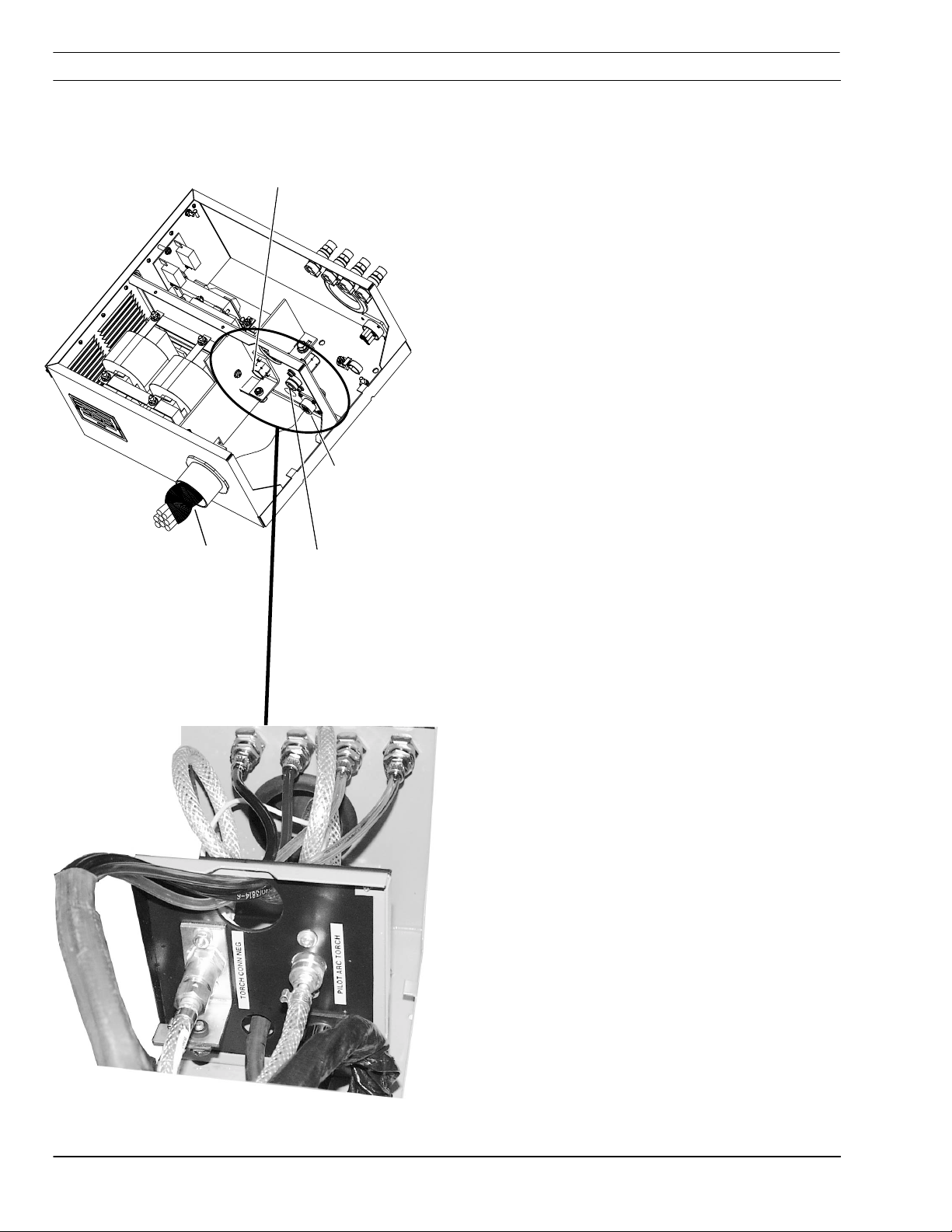
SECTION 3 INSTALLATION
Power Source
Rating
Label
Pilot Arc
Work
Torch
600 amp
Bus Fuse
Remove Access Cover
Pilot Arc
Work
Torch
CNC Control Lead
Flow Control
Lead
7. Remove panel from rear of console and attach the
pilot-arc, torch and work lead.
Serial
Tag
8. Connect control lead between the console and the
Electronic Flow Control. Connect coolant lines of
the Power Bundle.
Coolant In from Torch
# 6 Connection
Coolant Out to Torch
CONTROL LEAD
3-9
Page 30

SECTION 3 INSTALLATION
3.6 Torch Mounting
CAUTION
1.812" (46mm)
Diameter Collar
" (51mm)
2.0
Diameter Sleeve
Vent Hole
Do Not Cover Vent Hole.
When mounting, do not to cover the small vent hole in
When mounting, do not to cover the small vent hole in
When mounting, do not to cover the small vent hole inWhen mounting, do not to cover the small vent hole in
the side of the sleeve. This hole allows coolant to
the side of the sleeve. This hole allows coolant to
the side of the sleeve. This hole allows coolant tothe side of the sleeve. This hole allows coolant to
drain from inside the sleeve should a leak occur in a
drain from inside the sleeve should a leak occur in a
drain from inside the sleeve should a leak occur in adrain from inside the sleeve should a leak occur in a
service line.
service line.
service line.service line.
Torch Mounting Options.
Torch Mounting Options.
Torch Mounting Options.Torch Mounting Options.
• The torch is normally mounted by the 2.0 inch
diameter (51mm) sleeve. Do not cover vent hole.
• For custom alternative mounting, the torch can be
mounted by the 1.812" (46 mm) dia collar shown.
This insulated collar and its shoulder are machined
relative to the nozzle retainer thread on the torch
body.
• Use only specified mounting surfaces
3-10
Page 31

SECTION 3 INSTALLATION
3.7 Torch Coolant
T
O
L
I
P
C
R
L
O
R
T
N
O
C
T
N
E
R
R
U
C
RECISION PLASMARC
A
R
E
W
O
P
• Remove coolant fill cap at front of console and fill
coolant tank with 4 gallons (15 liters) of plasma
coolant, P/N 156F05 (one gallon).
Coolant
Fill Cap
CAUTION
!
• Do not fill above maximum level
• Reinstall Cap.
Commercial Antifreeze Will Cause Torch To
Malfunction
Use Special Torch Coolant! P/N156F05
Due to high electrical conductivity, DO NOT use tap
Due to high electrical conductivity, DO NOT use tap
Due to high electrical conductivity, DO NOT use tapDue to high electrical conductivity, DO NOT use tap
water or commercial antifreeze for torch cooling. A
water or commercial antifreeze for torch cooling. A
water or commercial antifreeze for torch cooling. Awater or commercial antifreeze for torch cooling. A
specially formulated torch coolant is REQUIRED. This
specially formulated torch coolant is REQUIRED. This
specially formulated torch coolant is REQUIRED. Thisspecially formulated torch coolant is REQUIRED. This
coolant also protects for freezing to –34° C.
coolant also protects for freezing to –34° C.
coolant also protects for freezing to –34° C.coolant also protects for freezing to –34° C.
3.8 Inspection of Gas and Coolant Lines
Operating the unit without coolant will cause
Operating the unit without coolant will cause
Operating the unit without coolant will causeOperating the unit without coolant will cause
permanent damage to the coolan t pu mp.
permanent damage to the coolan t pu mp.
permanent damage to the coolan t pu mp.permanent damage to the coolant pump .
To complete installation, it is necessary to inspect
field assembled connections for leaks.
• Gas lines, use a standard soap solution.
Pressurize the system from the control (SDP file)
• Coolant- check connections for signs of
moisture at connections
3-11
Page 32

SECTION 3 INSTALLATION
3.9 Replacement of EPROM in the Plasmarc Power Source Programmable Logic
Controller (PLC)
The Precision Plasmarc System may be shipped
configured for a manual flow control (Series “A”). If
so, the EPROM in the Programmable Logic
Controller must be replaced with an EFC EPROM.
This EFC EPROM is shipped with the power source.
Using the Wrong EPROM Could Result In
CAUTION
!
CAUTION
!
Damaged System Components
The Series “A” and the EFC EPROMs are
programmed with different software. The EFC
EPROM ignores the process gas pressure
switch inputs and does not include the
process gas purge required for the Series “A”.
Mishandling Can Damage Electronic
Components.
CAUTION
!
WARNING
!
Handle electronic components with care.
• Do not drop
• Do not bend pins
• Do not touch circuit components- handle
along edges when possible
Electronic Components Are Subject To
Electro-Static-Discharge (ESD) Damage
Integrated Circuit parts are sensitive to over
voltages. The damage may not be seen
immediately but show up as a premature
failure.
The EFC EPROM is shipped in an anti-static
bag. Store EPROM in this bag.
Wear a protective ground strap when handling
sensitive electronic components.
Electric shock Can Kill!
Unplug power cable from wall to power source
before any connections or adjustments are
made inside power source.
3-12
Page 33

SECTION 3 INSTALLATION
T
O
I
P
L
C
R
A
R
E
W
O
P
C
R
A
M
S
A
L
P
N
O
I
S
I
1. Ensure the Plasmarc Power Source is
disconnected from electricity source.
2. Expose the PLC by removing the left side panel
of the Plasmarc Power Source.
3. Pop the EPROM cover on the PLC to expose
the EPROM.
PLC
Left Side Panel
L
O
R
T
N
O
C
N
T
E
R
R
U
C
C
E
R
EFC EPROM
Package Location
3-13
Page 34

SECTION 3 INSTALLATION
Using An EPROM Puller Tool May Damage
CAUTION
EPROM Locked In Place
Socket
Forcibly removing a clamped EPROM in the
PLC may cause the socket/EPROM to break.
Special Zero Force EPROM Socket is used to
eliminate the need for special tools.
4. Remove the EPROM from the socket. THIS
DOES NOT REQUIRE A PULLER. Release the
clamp locking the EPROM in place, lift the
Series “A” EPROM from the socket.
5. Remove the EFC EPROM from the packaging.
6. Carefully align the EFC EPROM pins with the
socket holes and insert.
7. Lock the EPROM by moving th e l eve r back
while holding the EPROM in place.
EPROM Lock Released
8. Replace the EPROM cover and the Power
Source left side panel.
EPPESA= Series “A” EPROM, manual flow control
P/N 99513607
EPPSEFC= EFC EPROM, electronic flow con t ro l
P/N 99513608
3-14
Page 35

SECTION 4 OPERATION
ARC
4.1 Power Supply Controls
4.1.1 Main Power Switch
LOW
EMERGENCY
STOP
DO NOT SWITCH
WHILE CUTTING
Main Power Switch
Controls the input power to the fan, water cooler and
the PC Board. Amber indicator light to the left of the
switch.
4.1.2 Pilot Arc Switch
EMERGENCY
STOP
CAUTION
Pilot Arc Switch
Used to select HIGH or LOW Start Pilot Arc depending
on cutting conditions. See Process Data for more
information on which conditions High and Low Start
are used.
POWER
ON
OFF
Adjusting Pilot Arc While in Operation Could
Damage Torch.
Do not adjust pilot arc switch while in operation.
Adjust before torch starts.
4-1
Page 36

SECTION 4 OPERATION
4.1.3 Fault Indicator Lights
Fault Indicator Lights
• Coolant flow will show low coolant flow. When
unit is turned on, the light will briefly show a fault
and then go out.
• Plasma Gas Pressure fault indicator -- low
Plasma Gas Pressure. Torch will not fire when
indicated. Not used for the E FC.
• Start Gas Pressure fault indicator -- low start gas
pressure. Torch will not fire when indicated. Not
used for the EFC.
used for the EFC.
used for the EFC.used for the EFC.
• P/S Temp fault indicator -- over temperature in the
inverter power source. Power source will shut
down.
• P/S Fault Indicator – fault in plasma control PCB
in the inverter power source. Power source will
shut down.
• Over-Under Voltage fault Indicator -- indicate
input voltage is above or below the tolerances of
the PCU console. Will latch until power is recycled
by main power switch.
• Emergency Stop fault indicator -- shows CNC
Interlock condition. Power Source will not work.
Not used for the EFC.
Not used for the EFC.Not used for the EFC.
Not
NotNot
4.1.4 Meters
4.1.5 Current Control Switch
• Cutting Cu rre nt Meter (A) -- Displays actual
cutting current in amperes.
• Cutting Vo ltage Meter (V) -- Displays actual
cutting voltage.
Control Remote/Panel Switch
• Panel Positi on – Output current is set by the
output current dial
• Out p ut Curr ent Dial – sets the cutting current
when current setting is made from the console
front panel. Dial reads 0 to 99.9 amps. 70.0 amps
shown.
• Remote Position – output current is set by the
CNC (or remote pot) with an analog dc signal
4-2
0-10 Vdc = 0-100 Adc
Page 37

SECTION 4 OPERATION
4.2 Cut Quality
4.2.1 Introduction
Causes affecting cut quality are interdependent.
Changing one variable affects all others. Determining a
solution may be difficult. The following guide offers
possible solutions to different undesirable cutting
results. To begin select the most prominent condition:
§ 4.2.2 Cut Angle, negative or positive
§ 4.2. 3 Cut not flat, rounded or undercut
§ 4.2.4 Surface roughness
§ 4.2.5 Dross
Usually the recommended cutting parameters will give
optimal cut quality, occasionally conditions may vary
enough that slight adjustments will be required. If so:
• Make small incremental adjustments when
making corrections.
• Adjust Arc Voltage in 5 volt increments, up or
down as required.
• Adjust cutting speed 5% or less as required
until conditions improve.
NOTICE
4.2.2 Cut Angle
Part
Before attempting ANY corrections, check cutting
variables with the factor y recommended
settings/consumable part numbers listed in
Process Data.
Negative Cut Angle
Top dimension is greater than the bottom.
• Misaligned torch
• Bent or warped material
• Worn or damaged consumables
• Standoff low (arc voltage)
• Cutting speed slow (machine travel rate)
Drop
Part
4-3
Page 38

SECTION 4 OPERATION
Positive Cut Angle
Part
Top dimension is less than the bottom dimension.
• Misaligned torch
• Bent or warped material
• Worn or damaged consumables
• High standoff High (arc voltage)
• Cutting speed fast
• Current high or low. (See Process Data for
PartDrop
recommended current level for specific nozzles).
4.2.3 Cut Flatness
Drop
Top And Bottom Rounded
Condition usually occurs when material is .25” thick
(6,4mm) or less.
• High current for given material thickness (See
Process Data for proper settings).
Part
4-4
Page 39
SECTION 4 OPERATION
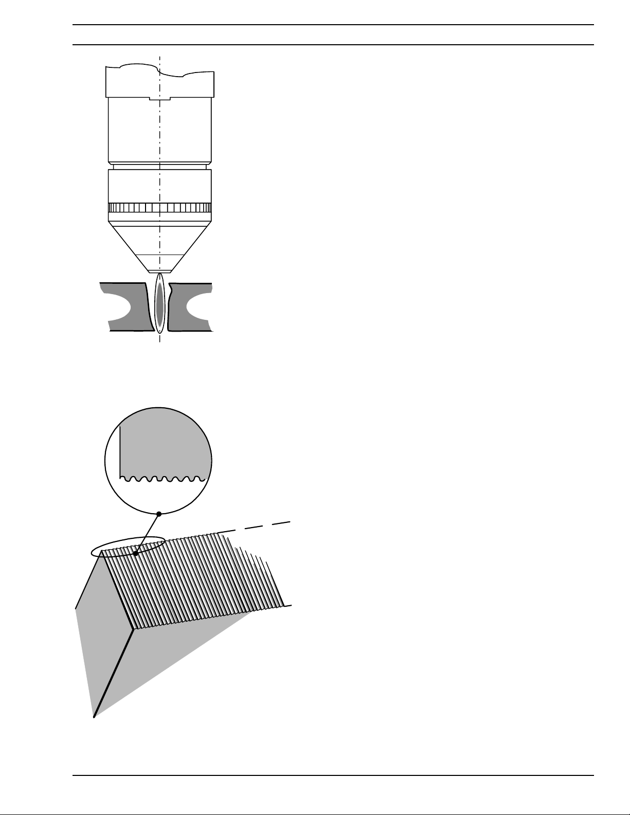
Top Edge Undercut
• Standoff low (Arc Voltage)
Drop
4.2.4 Surface Finish
Top View
Part
Process Induced Roughness
Cut face is consistently rough. May or may not be
confined to one axis.
• Incorrect Shield Gas mixture (See Process Data)
• Worn or damaged consumables
Cut Face
MMMMachine Induced Roughness
Can be difficult to distinguish from Process Induced
Roughness. Often confined to only one axis.
Roughness is inconsistent.
or
Process
Induced
Roughness
Machine
Induced
Roughness
• Dirty rails, wheels and/or drive rack/pinion. (Refer
to Maintenance Section in machine owners
manual).
• Carriage wheel adjustment
4-5
Page 40

SECTION 4 OPERATION
4.2.5 Dross
Dross is a by-product of the cutting process. It is the
undesirable material that remains attached to the part.
In most cases, dross can be reduced or eliminated
with proper torch and cutting parameter setup. Refer
to Process Data.
Cut
Lag
Lines
Face
High Speed Dross
Material weld or rollover on bottom surface along kerf.
Difficult to remove. May require grinding or chipping.
“S” shaped lag lines.
Rollover
• Standoff high (arc voltage)
Side View
Lag
Lines
• Cutting speed fast
Cut Face
Slow Speed Dross
Forms as globules on bottom along kerf. Removes
easily.
Globules
• Cutting speed slow
Side View
4-6
Page 41

SECTION 4 OPERATION
Side View
Splatter
Top Dross
Appears as splatter on top of material. Usually
removes easily.
• Cutting speed fast
• Standoff high (arc voltage).
Cut
Face
Intermittent Dross
Appears on top or bottom along kerf.
Non-continuous. Can appear as any kind of dross
• Possible worn consumables
Other Factors Affecting Dross;
• Material temperature
• Heavy mill scale or rust
• High carbon alloys
4-7
Page 42

SECTION 4 OPERATION
4.2.6 Dimensional Accuracy
Generally using the slowest possible speed (within
approved levels) will optimize part accuracy. Select
consumables to allow a lower arc voltage and slower
cutting speed.
NOTICE
NOTICE
Recommended cutting speed and arc voltage will
give optimal cutting performance in most cases.
Small incremental adjustments may be needed
due to material quality, material temperature and
specific alloy. The operator should remember
that all cutting variables are interdependent.
Changing one setting affects all others and cut
quality could deteriorate. Always start at the
recommended settings.
Before attempting ANY corrections, check
cutting variables with the factory recommended
settings/consumable part numbers listed in the
Process Data.
4-8
Page 43

SECTION 4 OPERATION
4.3 Influence of Gas Options on Cut Quality
4.3.1 Introduction
All gases are not suitable for all situations. Certain
gases assist in cutting specific materials and
thickness. The f ollowing explains w h y certain gases
are selected and their influence on the finished part.
Other influences such as arc voltage and gas
flow/pressure are covered in the Process Data.
NOTICE
4.3.2 Aluminum
Material Thickness:
Material Thickness:
Material Thickness:Material Thickness:
Cut Qualities:
Cut Qualities:
Cut Qualities:Cut Qualities:
Plasma Gas:
Plasma Gas: Nitrogen
Plasma Gas:Plasma Gas:
All thickness’ between .062" to .625" (1,6 mm to 15,9 mm)
• Smooth cut face
• Virtually no dross
Shield Gas:
Shield Gas: Nitrogen/Methane
Shield Gas:Shield Gas:
Discussion:
Discussion:
Discussion:Discussion:
Shield mixture is very important. Between 2 and 3 parts nitrogen, to 1
part methane ratio is desired. Incorrect ratio results in heavy dross.
Refer to Cutting Process Data in this section for
recommended flow/pressure settings.
4-9
Page 44

SECTION 4 OPERATION
Refer to Cutting Process Data in the PT24
NOTICE
4.3.3 Carbon Steel
Material Thickness:
Material Thickness:
Material Thickness:Material Thickness:
26 GA (.018") to 10 GA (.135") (0,5 mm to 3,4 mm)
Manual for recommended flow/pressure
settings.
Cut Qualities:
Cut Qualities:
Cut Qualities:Cut Qualities:
Plasma Gas:
Plasma Gas: Oxygen
Plasma Gas:Plasma Gas:
Shield Gas:
Shield Gas: Oxygen/Nitrogen
Shield Gas:Shield Gas:
Discussion:
Discussion:
Discussion:Discussion:
Material Thickness:
Material Thickness:
Material Thickness:Material Thickness:
Cut Qualities:
Cut Qualities:
Cut Qualities:Cut Qualities:
Plasma Gas:
Plasma Gas: Oxygen
Plasma Gas:Plasma Gas:
Shield Gas:
Shield Gas: Nitrogen
Shield Gas:Shield Gas:
• Smooth cut face
• Virtually no dross
Shield gas is normally nitrogen. A small amount of oxygen combined
with nitrogen can effectively improve dross formation on thin material of
26 GA to 10 GA carbon steel. Also, an oxygen only shield may provide
acceptable results on thinner materials.
.125" to .75" (3,2 mm to 19,1 mm)
• Smooth cut face
• Virtually no dross
Discussion:
Discussion:
Discussion:Discussion:
Cutting carbon steel with oxygen results in an exothermic reaction. This
chemical reaction causes the carbon in the material to burn similar to
when oxy-fuel cutting. This plus the elect ric al en ergy uses lower
amperage levels without sacrificing cut speed.
4-10
Page 45

SECTION 4 OPERATION
Refer to Cutting Process Data in the PT24
NOTICE
Manual for recommended flow/pressure
settings.
4.3.4 Stainless Steel
Material Thickness:
Material Thickness:
Material Thickness:Material Thickness:
22 GA (.028") to 16 GA (.062") (0,7 mm to 1,6 mm)
• Positive cut angle
Cut Qualities:
Cut Qualities:
Cut Qualities:Cut Qualities:
• Excellent dross performance
• Shiny cut surface.
Plasma Gas:
Plasma Gas: Nitrogen
Plasma Gas:Plasma Gas:
Shield Gas:
Shield Gas: Nitrogen/Methane
Shield Gas:Shield Gas:
Discussion:
Discussion:
Discussion:Discussion:
Material Thickness:
Material Thickness: 26 GA (.018") to 16 GA (.062") (0,5 mm to 1,6 mm)
Material Thickness:Material Thickness:
Because of high cut speeds, a positive cut face angle is expected. Use
a 70-amp nozzle at 50 amps to allow more gas to exit the nozzle.
• Dark cut face
Cut Qualities:
Cut Qualities:
Cut Qualities:Cut Qualities:
• Virtually dross free
• Improved cut squareness
Plasma Gas:
Plasma Gas: Oxygen
Plasma Gas:Plasma Gas:
Shield Gas:
Shield Gas: Oxygen/Nitrogen
Shield Gas:Shield Gas:
Low amperage cutting/slower speeds produce squarer cuts in thin
Discussion:
Discussion:
Discussion:Discussion:
Material Thickness:
Material Thickness: .125" to .625" (3,2 mm to 15,9 mm)
Material Thickness:Material Thickness:
materials. The oxygen allows for a lower arc voltage, improvin g cu t
squareness. The “B” nozzle is used at 30 amps
• Cut edge dark
Cut Qualities:
Cut Qualities:
Cut Qualities:Cut Qualities:
• good dross performance
• Good cut angle
Plasma Gas:
Plasma Gas: Air
Plasma Gas:Plasma Gas:
Shield Gas:
Shield Gas: Air
Shield Gas:Shield Gas:
When they are the same, the shield and plasma gases combine. This
Discussion:
Discussion:
Discussion:Discussion:
combination has the effect of increasing the cut gas flow/pressure. This
increased flow/pressure directly influences cut squareness.
4-11
Page 46

SECTION 4 OPERATION
Stainless Steel
Material Thickness:
Material Thickness: .125" to .625" (3,2 mm to 15,9 mm)
Material Thickness:Material Thickness:
NOTICE
• Matted cut edge appearan ce
Cut Qualities:
Cut Qualities:
Cut Qualities:Cut Qualities:
Plasma Gas:
Plasma Gas: Air
Plasma Gas:Plasma Gas:
Shield Gas:
Shield Gas: Air/Methane
Shield Gas:Shield Gas:
Discussion:
Discussion:
Discussion:Discussion:
• Light gray color
• Much smoother finish
• Possible slight increase in cut angle
Too much methane in the shield gas mixture can result in more dross
formation. 4:1 ratio air to methane is recommended. Because methane
is a fuel gas, possible slight increase in cut angles could be experienced.
Refer to Cutting Process Data for recommended
flow/pressure settings.
Material Thickness:
Material Thickness: .125" to .625" (3,2 mm to 15,9 mm)
Material Thickness:Material Thickness:
• Dark cut face similar to air
Cut Qualities:
Cut Qualities:
Cut Qualities:Cut Qualities:
• Excellent dross performance
• Good cut angle
Plasma Gas:
Plasma Gas: Nitrogen
Plasma Gas:Plasma Gas:
Shield Gas:
Shield Gas: Nitrogen
Shield Gas:Shield Gas:
Shield and plasma gases combine, the volume/pressure of shield gas
Discussion:
Discussion:
Discussion:Discussion:
Material Thickness:
Material Thickness: .187" to .625" (4,7 mm to 15,9 mm)
Material Thickness:Material Thickness:
can negatively affect cut squareness. Higher shield volume produces a
negative cut angle. A lower volume, produces a positive angle.
• Shiny cut face
Cut Qualities:
Cut Qualities:
Cut Qualities:Cut Qualities:
• Lip formation at the bottom
• Dross formation can be extensive and difficult to remove
Plasma Gas:
Plasma Gas: Nitrogen
Plasma Gas:Plasma Gas:
Shield Gas:
Shield Gas: Nitrogen/Methane
Shield Gas:Shield Gas:
Discussion:
Discussion:
Discussion:Discussion:
Because methane is a fuel gas, flow/pressure rates can affect the cut
angle. High flow/pressure results in a negative cut angle, low
flow/pressure results in a positive cut angle. Nitrogen to methane ratio is
10 to 14 parts N
severe, making Nitrogen/Methane shield gas combination unsuitable for
some finished part applications.
/ 1 part CH4. The lip formed on the cut face bottom is
2
4-12
Page 47

SECTION 4 OPERATION
4.4 Process Data
4.4.1 Introduction
4.4.1 Introduction
4.4.1 Introduction4.4.1 Introduction
The following information is a result of many hours of
testing and is a general guide for setting up and
cutting with a PT-24 Precision Plasmarc System. In
most cases these settings will provide a quality cut.
The data contains values for:
• cutting aluminum, carbon and stainless steel
• arc voltage (standoff)
• cutting speed
• current (amperes)
• gas flow rates for all plasma/shield gas
combinations
This same data is contained in SDP files. (See your
control manual for more information on SDP files.)
Also included is information on consumable part
numbers for current being used.
4-13
Page 48

SECTION 4 OPERATION
(
)
)
4.4.2 Process Data
PT-24 Torch
Material:
Amperes:
Plasm a Gas:
Shield Gas:
Shield Mix Gas:
Aluminum
30
Nitrogen @ 125 PSI / 8.6 Bar
Nitrogen @ 125 PSI / 8.6 Bar
Methane @ 100 PSI / 6.9 Bar
Torch Body
Torch Body
Torch BodyTorch Body
P/N 21758
P/N 21758
P/N 21758P/N 21758
Water Baffle
Water Baffle
Water BaffleWater Baffle
P/N 21725
P/N 21725
P/N 21725P/N 21725
O-Ring
O-Ring
O-RingO-Ring
P/N 638797
P/N 638797
P/N 638797P/N 638797
O-Ring
O-Ring
O-RingO-Ring
P/N 86W62
P/N 86W62
P/N 86W62P/N 86W62
O-Ring
O-Ring
O-RingO-Ring
P/N 950714
P/N 950714
P/N 950714P/N 950714
O-Ring
O-Ring
O-RingO-Ring
P/N 98W18
P/N 98W18
P/N 98W18P/N 98W18
Electrode
Electrode
ElectrodeElectrode
P/N 21539
P/N 21539
P/N 21539P/N 21539
Swirl Baffle
Swirl Baffle
Swirl Baffle Swirl Baffle
P/N
P/N 21536 (3 holes)
21536 (3 holes)
21536 (3 holes
P/N P/N
21536
Nozzle
Nozzle
Nozzle Nozzle
P/N
P/N 21541, "B"
21541, "B"
P/N P/N
21541, "B"21541, "B"
Nozzle Retainer/D if fu ser
Nozzle Retainer/D if fu ser
Nozzle Retainer/D if fu serNozzle Retainer/D if fu ser
P/N 22007
P/N 22007
P/N 22007P/N 22007
Shield Cup Insulat or
Shield Cup Insulat or
Shield Cup Insulat orSh ield Cup Insu l a to r
P/N 22010
P/N 22010
P/N 22010P/N 22010
Insulator Shield Reta in er
Insulator Shield Reta in er
Insulator Shield Reta in erInsulat or Sh ie ld Reta in er
w/O-Ring P/N 21712
w/O-Ring P/N 21712
w/O-Ring P/N 21712w/O-Ring P/N 21712
3 holes
O-Ring
O-Ring - Shield
O-Ring O-Ring
(Ref. P/N 996528)
(Ref. P/N 996528)
(Ref. P/N 996528)(Ref. P/N 996528)
Cup shield w/Retainer
Cup shield w/Retainer
Cup shield w/RetainerCup shield w/Retainer
P/N 22531
P/N 22531
P/N 22531P/N 22531
Baffle and Nozzle
are the only two
replaceable torch
front-end parts that
may vary with
amperage
4-14
- Shield Retainer .
- Shield - Shield
Retainer .
Retainer .Retainer .
Page 49

SECTION 4 OPERATION
Process Data
Material Thickness
IN 0.062 0.075 0.090 0.125 0.187 0.250
MM 1,61,92,33,24,76,4
Pierce Delay (SEC.)
Setup Parameters (see notes)
Plasma Start Gas 1
Plasma Cut Gas 1
SG1-Start 454545454545
30 Amperes
Aluminum
PG
PG SG1
PGPG
N2 N2 CH4
000000
40 40 40 40 40 40
55 55 55 55 55 55
SG1 SG2
SG1SG1
SG2
SG2SG2
Shield Gas
(Flow Reading)
Flow Reading
SG1- Cut 202020202020
SG2- Cut Flow 10 10 10 10 10 10
Arc Voltage (standoff)
Travel Speed
IPM
MM/MIN
Notes:
1. Pilot Arc –LOW.
2. Cut and ALT gas mix in Flow Control.
3. Float – Center of Ball
150 152 153 158 170 189
150 135 105 78 30 25
3810 3429 2667 1981 762 635
4-15
Page 50

SECTION 4 OPERATION
(
)
)
PT-24 Torch
Material:
Amperes:
Plasm a Gas:
Shield Gas:
Shield Mix Gas:
Aluminum
55
Nitrogen @ 125 PSI / 8.6 Bar
Nitrogen @ 125 PSI / 8.6 Bar
Methane @ 100 PSI / 6.9 Bar
Torch Body
Torch Body
Torch BodyTorch Body
P/N 21758
P/N 21758
P/N 21758P/N 21758
Water Baffle
Water Baffle
Water BaffleWater Ba ff le
P/N 21725
P/N 21725
P/N 21725P/N 21725
O-Ring
O-Ring
O-RingO-Ring
P/N 638797
P/N 638797
P/N 638797P/N 638797
O-Ring
O-Ring
O-RingO-Ring
P/N 86W62
P/N 86W62
P/N 86W62P/N 86W62
O-Ring
O-Ring
O-RingO-Ring
P/N 950714
P/N 950714
P/N 950714P/N 950714
O-Ring
O-Ring
O-RingO-Ring
P/N 98W18
P/N 98W18
P/N 98W18P/N 98W18
Electrode
Electrode
ElectrodeElectrode
P/N 21539
P/N 21539
P/N 21539P/N 21539
Swirl Baffle
Swirl Baffle
Swirl Baffle Swirl Baffle
P/N
P/N 21692 (4 holes)
21692 (4 holes)
21692 (4 holes
P/N P/N
21692
Nozzle
Nozzle
Nozzle Nozzle
P/N
P/N 21542, "C"
21542, "C"
P/N P/N
21542, "C"21542, "C"
Nozzle Retainer/D if fu ser
Nozzle Retainer/D if fu ser
Nozzle Retainer/D if fu serNozzle Retainer/D if fu ser
P/N 22007
P/N 22007
P/N 22007P/N 22007
Shield Cup Insulat or
Shield Cup Insulat or
Shield Cup Insulat orSh ield Cup Insu l a to r
P/N 22010
P/N 22010
P/N 22010P/N 22010
Insulator Shield Reta in er
Insulator Shield Reta in er
Insulator Shield Reta in erInsulat or Sh ie ld Reta in er
w/O-Ring P/N 21712
w/O-Ring P/N 21712
w/O-Ring P/N 21712w/O-Ring P/N 21712
4 holes
O-Ring
O-Ring - Shield
O-Ring O-Ring
(Ref. P/N 996528)
(Ref. P/N 996528)
(Ref. P/N 996528)(Ref. P/N 996528)
Cup shield w/Retainer
Cup shield w/Retainer
Cup shield w/RetainerCup shield w/Retainer
P/N 22531
P/N 22531
P/N 22531P/N 22531
Baffle and Nozzle
are the only two
replaceable torch
front-end parts that
may vary with
amperage
4-16
- Shield Retainer .
- Shield - Shield
Retainer .
Retainer .Retainer .
Page 51

SECTION 4 OPERATION
Process Data
Material Thickness
IN 0.062 0.125 0.187 0.250
MM 1,6 3,2 4,7 6,4
Pierce Delay (SEC.)
Setup Parameters (see notes)
Plasma Start Gas 1
Plasma Cut Gas 1
SG1-Start 55555555
55 Amperes
Aluminum
PG
PG SG1
PGPG
N2 N2 CH4
0000
45 45 45 45
75 75 75 85
SG1 SG2
SG1SG1
SG2
SG2SG2
Shield Gas
(Flow Reading)
Flow Reading
SG1- Cut 20202020
SG2- Cut Flow 10 10 10 10
Arc Voltage (standoff)
Travel Speed
IPM
MM/MIN
Notes:
1. Pilot Arc –HIGH.
2. Cut and ALT gas mix in Flow Control.
3. Float – Center of Ball
136 139 152 168
170 130 78 46
4318 3302 1981 1168
4-17
Page 52

SECTION 4 OPERATION
(
)
)
PT-24 Torch
Material:
Amperes:
Plasm a Gas:
Shield Gas:
Shield Mix Gas:
Aluminum
70
Nitrogen @ 125 PSI / 8.6 Bar
Nitrogen @ 125 PSI / 8.6 Bar
Methane @ 100 PSI / 6.9 Bar
Torch Body
Torch Body
Torch BodyTorch Body
P/N 21758
P/N 21758
P/N 21758P/N 21758
Water Baffle
Water Baffle
Water BaffleWater Ba ff le
P/N 21725
P/N 21725
P/N 21725P/N 21725
O-Ring
O-Ring
O-RingO-Ring
P/N 638797
P/N 638797
P/N 638797P/N 638797
O-Ring
O-Ring
O-RingO-Ring
P/N 86W62
P/N 86W62
P/N 86W62P/N 86W62
O-Ring
O-Ring
O-RingO-Ring
P/N 950714
P/N 950714
P/N 950714P/N 950714
O-Ring
O-Ring
O-RingO-Ring
P/N 98W18
P/N 98W18
P/N 98W18P/N 98W18
Electrode
Electrode
ElectrodeElectrode
P/N 21539
P/N 21539
P/N 21539P/N 21539
Swirl Baffle
Swirl Baffle
Swirl Baffle Swirl Baffle
P/N
P/N 21692 (4 holes)
21692 (4 holes)
21692 (4 holes
P/N P/N
21692
Nozzle
Nozzle
Nozzle Nozzle
P/N
P/N 21543, "D"
21543, "D"
P/N P/N
21543, "D"21543, "D"
Nozzle Retainer/D if fu ser
Nozzle Retainer/D if fu ser
Nozzle Retainer/D if fu serNozzle Retainer/D if fu ser
P/N 22007
P/N 22007
P/N 22007P/N 22007
Shield Cup Insulat or
Shield Cup Insulat or
Shield Cup Insulat orSh ield Cup Insu l a to r
P/N 22010
P/N 22010
P/N 22010P/N 22010
Insulator Shield Reta in er
Insulator Shield Reta in er
Insulator Shield Reta in erInsulat or Sh ie ld Reta in er
w/O-Ring P/N 21712
w/O-Ring P/N 21712
w/O-Ring P/N 21712w/O-Ring P/N 21712
4 holes
O-Ring
O-Ring - Shield
O-Ring O-Ring
(Ref. P/N 996528)
(Ref. P/N 996528)
(Ref. P/N 996528)(Ref. P/N 996528)
Cup shield w/Retainer
Cup shield w/Retainer
Cup shield w/RetainerCup shield w/Retainer
P/N 22531
P/N 22531
P/N 22531P/N 22531
Baffle and Nozzle
are the only two
replaceable torch
front-end parts that
may vary with
amperage
4-18
- Shield Retainer .
- Shield - Shield
Retainer .
Retainer .Retainer .
Page 53

SECTION 4 OPERATION
Process Data
Material Thickness
IN 0.187 0.250 0.375 0.500
MM 4,7 6,4 9,5 12,7
Pierce Delay (SEC.)
Setup Parameters (see notes)
Plasma Start Gas 1
Plasma Cut Gas 1
SG1-Start 45454545
70 Amperes
Aluminum
PG
PG SG1
PGPG
N2 N2 CH4
0 0 0.1 0.2
65 65 65 65
50 50 100 100
SG1 SG2
SG1SG1
SG2
SG2SG2
Shield Gas
(Flow Reading)
Flow Reading
SG1- Cut 20202020
SG2- Cut Flow 10 10 10 10
Arc Voltage (standoff)
Travel Speed
IPM
MM/MIN
Notes:
1. Pilot Arc –HIGH.
2. Cut and ALT gas mix in Flow Control.
3. Float – Center of Ball
150 157 168 182
80 65 55 30
2032 1651 1397 762
4-19
Page 54

SECTION 4 OPERATION
(
)
)
PT-24 Torch
Material:
Amperes:
Plasm a Gas:
Shield Gas:
Shield Mix Gas:
Aluminum
100
Nitrogen @ 125 PSI / 8.6 Bar
Nitrogen @ 125 PSI / 8.6 Bar
Methane @ 100 PSI / 6.9 Bar
Torch Body
Torch Body
Torch BodyTorch Body
P/N 21758
P/N 21758
P/N 21758P/N 21758
Water Baffle
Water Baffle
Water BaffleWater Ba ff le
P/N 21725
P/N 21725
P/N 21725P/N 21725
O-Ring
O-Ring
O-RingO-Ring
P/N 638797
P/N 638797
P/N 638797P/N 638797
O-Ring
O-Ring
O-RingO-Ring
P/N 86W62
P/N 86W62
P/N 86W62P/N 86W62
O-Ring
O-Ring
O-RingO-Ring
P/N 950714
P/N 950714
P/N 950714P/N 950714
O-Ring
O-Ring
O-RingO-Ring
P/N 98W18
P/N 98W18
P/N 98W18P/N 98W18
Electrode
Electrode
ElectrodeElectrode
P/N 21539
P/N 21539
P/N 21539P/N 21539
Swirl Baffle
Swirl Baffle
Swirl Baffle Swirl Baffle
P/N
P/N 21692 (4 holes)
21692 (4 holes)
21692 (4 holes
P/N P/N
21692
Nozzle
Nozzle
Nozzle Nozzle
P/N
P/N 21923, "E"
21923, "E"
P/N P/N
21923, "E"21923, "E"
Nozzle Retainer/D if fu ser
Nozzle Retainer/D if fu ser
Nozzle Retainer/D if fu serNozzle Retainer/D if fu ser
P/N 22007
P/N 22007
P/N 22007P/N 22007
Shield Cup Insulat or
Shield Cup Insulat or
Shield Cup Insulat orSh ield Cup Insu l a to r
P/N 22010
P/N 22010
P/N 22010P/N 22010
Insulator Shield Reta in er
Insulator Shield Reta in er
Insulator Shield Reta in erInsulat or Sh ie ld Reta in er
w/O-Ring P/N 21712
w/O-Ring P/N 21712
w/O-Ring P/N 21712w/O-Ring P/N 21712
4 holes
O-Ring
O-Ring - Shield
O-Ring O-Ring
(Ref. P/N 996528)
(Ref. P/N 996528)
(Ref. P/N 996528)(Ref. P/N 996528)
Cup shield w/Retainer
Cup shield w/Retainer
Cup shield w/RetainerCup shield w/Retainer
P/N 22531
P/N 22531
P/N 22531P/N 22531
Baffle and Nozzle
are the only two
replaceable torch
front-end parts that
may vary with
amperage
4-20
- Shield Retainer .
- Shield - Shield
Retainer .
Retainer .Retainer .
Page 55

SECTION 4 OPERATION
Process Data
Material Thickness
IN 0.250 0.375 0.500 0.625
MM 6,4 9,5 12,7 15,9
Pierce Delay (SEC.)
Setup Parameters (see notes)
Plasma Start Gas 1
Plasma Cut Gas 1
SG1-Start 60606060
100 Amperes
Aluminum
PG
PG SG1
PGPG
N2 N2 N2
0 0 0.1 0.1
80 80 80 80
100 100 100 100
SG1 SG2
SG1SG1
SG2
SG2SG2
Shield Gas
(Flow Reading)
Flow Reading
SG1- Cut 31313131
SG2- Cut Flow 10 10 10 10
Arc Voltage (standoff)
Travel Speed
IPM
MM/MIN
Notes:
1. Pilot Arc –HIGH.
2. Cut and ALT gas mix in Flow Control.
3. Float – Center of Ball
155 160 166 174
65 80 65 50
2413 2032 1778 1270
4-21
Page 56

SECTION 4 OPERATION
(
)
)
PT-24 Torch
Material:
Amperes:
Plasm a Gas:
Shield Gas:
Shield Mix Gas:
Carbon Steel
16
Oxygen @ 125 PSI / 8.6 Bar
Nitrogen @ 125 PSI / 8.6 Bar
Oxygen @ 125 PSI / 8.6 Bar
Torch Body
Torch Body
Torch BodyTorch Body
P/N 21758
P/N 21758
P/N 21758P/N 21758
Water Baffle
Water Baffle
Water BaffleWater Ba ff le
P/N 21725
P/N 21725
P/N 21725P/N 21725
O-Ring
O-Ring
O-RingO-Ring
P/N 638797
P/N 638797
P/N 638797P/N 638797
O-Ring
O-Ring
O-RingO-Ring
P/N 86W62
P/N 86W62
P/N 86W62P/N 86W62
O-Ring
O-Ring
O-RingO-Ring
P/N 950714
P/N 950714
P/N 950714P/N 950714
O-Ring
O-Ring
O-RingO-Ring
P/N 98W18
P/N 98W18
P/N 98W18P/N 98W18
Electrode
Electrode
ElectrodeElectrode
P/N 21539
P/N 21539
P/N 21539P/N 21539
Swirl Baffle
Swirl Baffle
Swirl Baffle Swirl Baffle
P/N
P/N 21852 (2 holes)
21852 (2 holes)
21852 (2 holes
P/N P/N
21852
Nozzle
Nozzle
Nozzle Nozzle
P/N
P/N 21540, "A"
21540, "A"
P/N P/N
21540, "A"21540, "A"
Nozzle Retainer/D if fu ser
Nozzle Retainer/D if fu ser
Nozzle Retainer/D if fu serNozzle Retainer/D if fu ser
P/N 22007
P/N 22007
P/N 22007P/N 22007
Shield Cup Insulat or
Shield Cup Insulat or
Shield Cup Insulat orSh ield Cup Insu l a to r
P/N 22010
P/N 22010
P/N 22010P/N 22010
Insulator Shield Reta in er
Insulator Shield Reta in er
Insulator Shield Reta in erInsulat or Sh ie ld Reta in er
w/O-Ring P/N 21712
w/O-Ring P/N 21712
w/O-Ring P/N 21712w/O-Ring P/N 21712
2 holes
O-Ring
O-Ring - Shield
O-Ring O-Ring
(Ref. P/N 996528)
(Ref. P/N 996528)
(Ref. P/N 996528)(Ref. P/N 996528)
Cup shield w/Retainer
Cup shield w/Retainer
Cup shield w/RetainerCup shield w/Retainer
P/N 22531
P/N 22531
P/N 22531P/N 22531
Baffle and Nozzle
are the only two
replaceable torch
front-end parts that
may vary with
amperage
4-22
- Shield Retainer .
- Shield - Shield
Retainer .
Retainer .Retainer .
Page 57

SECTION 4 OPERATION
Process Data
Material Thickness
IN 20GA 18GA 16GA 14GA 12GA 10GA
MM 0,91,21,62,02,73,4
Pierce Delay (SEC.)
Setup Parameters (see notes)
Plasma Start Gas 1
Plasma Cut Gas 1
SG1-Start 202020202020
16 Amperes
Carbon Steel
PG
PG SG1
PGPG
O2 N2 O2
0 0 0 0.1 0.5 0.1
20 20 20 20 20 20
11 11 11 11 11 11
SG1 SG2
SG1SG1
SG2
SG2SG2
Shield Gas
(Flow Reading)
Flow Reading
SG1- Cut 000000
SG2- Cut Flow666666
Arc Voltage (standoff)
Travel Speed
IPM
MM/MIN
Notes:
1. Pilot Arc –LOW.
2. Cut and ALT gas mix in Flow Control.
3. Float – Center of Ball
103 105 115 118 116 117
1008580605036
2540 2159 2032 1524 1270 914
4-23
Page 58

SECTION 4 OPERATION
(
)
)
PT-24 Torch
Material:
Amperes:
Plasm a Gas:
Shield Gas:
Shield Mix Gas:
Carbon Steel
35
Oxygen @ 125 PSI / 8.6 Bar
Nitrogen @ 125 PSI / 8.6 Bar
Oxygen @ 125 PSI / 8.6 Bar
Torch Body
Torch Body
Torch BodyTorch Body
P/N 21758
P/N 21758
P/N 21758P/N 21758
Water Baffle
Water Baffle
Water BaffleWater Ba ff le
P/N 21725
P/N 21725
P/N 21725P/N 21725
O-Ring
O-Ring
O-RingO-Ring
P/N 638797
P/N 638797
P/N 638797P/N 638797
O-Ring
O-Ring
O-RingO-Ring
P/N 86W62
P/N 86W62
P/N 86W62P/N 86W62
O-Ring
O-Ring
O-RingO-Ring
P/N 950714
P/N 950714
P/N 950714P/N 950714
O-Ring
O-Ring
O-RingO-Ring
P/N 98W18
P/N 98W18
P/N 98W18P/N 98W18
Electrode
Electrode
ElectrodeElectrode
P/N 21539
P/N 21539
P/N 21539P/N 21539
Swirl Baffle
Swirl Baffle
Swirl Baffle Swirl Baffle
P/N
P/N 21536 (3 holes)
21536 (3 holes)
21536 (3 holes
P/N P/N
21536
Nozzle
Nozzle
Nozzle Nozzle
P/N
P/N 21541, "B"
21541, "B"
P/N P/N
21541, "B"21541, "B"
Nozzle Retainer/D if fu ser
Nozzle Retainer/D if fu ser
Nozzle Retainer/D if fu serNozzle Retainer/D if fu ser
P/N 22007
P/N 22007
P/N 22007P/N 22007
Shield Cup Insulat or
Shield Cup Insulat or
Shield Cup Insulat orSh ield Cup Insu l a to r
P/N 22010
P/N 22010
P/N 22010P/N 22010
Insulator Shield Reta in er
Insulator Shield Reta in er
Insulator Shield Reta in erInsulat or Sh ie ld Reta in er
w/O-Ring P/N 21712
w/O-Ring P/N 21712
w/O-Ring P/N 21712w/O-Ring P/N 21712
3 holes
O-Ring
O-Ring - Shield
O-Ring O-Ring
(Ref. P/N 996528)
(Ref. P/N 996528)
(Ref. P/N 996528)(Ref. P/N 996528)
Cup shield w/Retainer
Cup shield w/Retainer
Cup shield w/RetainerCup shield w/Retainer
P/N 22531
P/N 22531
P/N 22531P/N 22531
Baffle and Nozzle
are the only two
replaceable torch
front-end parts that
may vary with
amperage
4-24
- Shield Retainer .
- Shield - Shield
Retainer .
Retainer .Retainer .
Page 59

SECTION 4 OPERATION
Process Data
Material Thickness
IN 14GA 0.125 0.135 0.187 0.250
MM 1,93,23,44,76,4
Pierce Delay (SEC.)
Setup Parameters (see notes)
Plasma Start Gas 1
Plasma Cut Gas 1
SG1-Start 5050505050
35 Amperes
Carbon Steel
PG
PG SG1
PGPG
O2 N2 O2
00000
38 38 38 38 38
15 15 15 15 15
SG1 SG2
SG1SG1
SG2
SG2SG2
Shield Gas
(Flow Reading)
Flow Reading
SG1- Cut 00000
SG2- Cut Flow66666
Arc Voltage (standoff)
Travel Speed
IPM
MM/MIN
Notes:
1. Pilot Arc –HIGH.
2. Cut and ALT gas mix in Flow Control.
3. Float – Center of Ball
113 119 120 122 124
80 55 52 40 30
3032 1397 1320 1016 762
4-25
Page 60

SECTION 4 OPERATION
(
)
)
PT-24 Torch
Material:
Amperes:
Plasm a Gas:
Shield Gas:
Shield Mix Gas:
Carbon Steel
45
Oxygen @ 125 PSI / 8.6 Bar
Nitrogen @ 125 PSI / 8.6 Bar
Oxygen @ 125 PSI / 8.6 Bar
Torch Body
Torch Body
Torch BodyTorch Body
P/N 21758
P/N 21758
P/N 21758P/N 21758
Water Baffle
Water Baffle
Water BaffleWater Ba ff le
P/N 21725
P/N 21725
P/N 21725P/N 21725
O-Ring
O-Ring
O-RingO-Ring
P/N 638797
P/N 638797
P/N 638797P/N 638797
O-Ring
O-Ring
O-RingO-Ring
P/N 86W62
P/N 86W62
P/N 86W62P/N 86W62
O-Ring
O-Ring
O-RingO-Ring
P/N 950714
P/N 950714
P/N 950714P/N 950714
O-Ring
O-Ring
O-RingO-Ring
P/N 98W18
P/N 98W18
P/N 98W18P/N 98W18
Electrode
Electrode
ElectrodeElectrode
P/N 21539
P/N 21539
P/N 21539P/N 21539
Swirl Baffle
Swirl Baffle
Swirl Baffle Swirl Baffle
P/N
P/N 21692 (4 holes)
21692 (4 holes)
21692 (4 holes
P/N P/N
21692
Nozzle
Nozzle
Nozzle Nozzle
P/N
P/N 21542, "C"
21542, "C"
P/N P/N
21542, "C"21542, "C"
Nozzle Retainer/D if fu ser
Nozzle Retainer/D if fu ser
Nozzle Retainer/D if fu serNozzle Retainer/D if fu ser
P/N 22007
P/N 22007
P/N 22007P/N 22007
Shield Cup Insulat or
Shield Cup Insulat or
Shield Cup Insulat orSh ield Cup Insu l a to r
P/N 22010
P/N 22010
P/N 22010P/N 22010
Insulator Shield Reta in er
Insulator Shield Reta in er
Insulator Shield Reta in erInsulat or Sh ie ld Reta in er
w/O-Ring P/N 21712
w/O-Ring P/N 21712
w/O-Ring P/N 21712w/O-Ring P/N 21712
4 holes
O-Ring
O-Ring - Shield
O-Ring O-Ring
(Ref. P/N 996528)
(Ref. P/N 996528)
(Ref. P/N 996528)(Ref. P/N 996528)
Cup shield w/Retainer
Cup shield w/Retainer
Cup shield w/RetainerCup shield w/Retainer
P/N 22531
P/N 22531
P/N 22531P/N 22531
Baffle and Nozzle
are the only two
replaceable torch
front-end parts that
may vary with
amperage
4-26
- Shield Retainer .
- Shield - Shield
Retainer .
Retainer .Retainer .
Page 61

SECTION 4 OPERATION
Process Data
Material Thickness
IN 0.125 0.135 0.187 0.250 0.375
MM 3,23,44,76,49,5
Pierce Delay (SEC.)
Setup Parameters (see notes)
Plasma Start Gas 1
Plasma Cut Gas 1
SG1-Start 5050505050
45 Amperes
Carbon Steel
PG
PG SG1
PGPG
O2 N2 O2
0.30.30.30.30.4
50 50 50 50 50
20 20 20 20 20
SG1 SG2
SG1SG1
SG2
SG2SG2
Shield Gas
(Flow Reading)
Flow Reading
SG1- Cut 1616161610
SG2- Cut Flow00000
Arc Voltage (standoff)
Travel Speed
IPM
MM/MIN
Notes:
1. Pilot Arc –HIGH.
2. Cut and ALT gas mix in Flow Control.
3. Float – Center of Ball
108 111 114 121 124
60 50 45 35 20
1524 1270 1143 889 508
4-27
Page 62

SECTION 4 OPERATION
(
)
)
PT-24 Torch
Material:
Amperes:
Plasm a Gas:
Shield Gas:
Shield Mix Gas:
Carbon Steel
70
Oxygen @ 125 PSI / 8.6 Bar
Nitrogen @ 125 PSI / 8.6 Bar
Oxygen @ 125 PSI / 8.6 Bar
Torch Body
Torch Body
Torch BodyTorch Body
P/N 21758
P/N 21758
P/N 21758P/N 21758
Water Baffle
Water Baffle
Water BaffleWater Ba ff le
P/N 21725
P/N 21725
P/N 21725P/N 21725
O-Ring
O-Ring
O-RingO-Ring
P/N 638797
P/N 638797
P/N 638797P/N 638797
O-Ring
O-Ring
O-RingO-Ring
P/N 86W62
P/N 86W62
P/N 86W62P/N 86W62
O-Ring
O-Ring
O-RingO-Ring
P/N 950714
P/N 950714
P/N 950714P/N 950714
O-Ring
O-Ring
O-RingO-Ring
P/N 98W18
P/N 98W18
P/N 98W18P/N 98W18
Electrode
Electrode
ElectrodeElectrode
P/N 21539
P/N 21539
P/N 21539P/N 21539
Swirl Baffle
Swirl Baffle
Swirl Baffle Swirl Baffle
P/N
P/N 21692 (4 holes)
21692 (4 holes)
21692 (4 holes
P/N P/N
21692
Nozzle
Nozzle
Nozzle Nozzle
P/N
P/N 21543, "D"
21543, "D"
P/N P/N
21543, "D"21543, "D"
Nozzle Retainer/D if fu ser
Nozzle Retainer/D if fu ser
Nozzle Retainer/D if fu serNozzle Retainer/D if fu ser
P/N 22007
P/N 22007
P/N 22007P/N 22007
Shield Cup Insulat or
Shield Cup Insulat or
Shield Cup Insulat orSh ield Cup Insu l a to r
P/N 22010
P/N 22010
P/N 22010P/N 22010
Insulator Shield Reta in er
Insulator Shield Reta in er
Insulator Shield Reta in erInsulat or Sh ie ld Reta in er
w/O-Ring P/N 21712
w/O-Ring P/N 21712
w/O-Ring P/N 21712w/O-Ring P/N 21712
4 holes
O-Ring
O-Ring - Shield
O-Ring O-Ring
(Ref. P/N 996528)
(Ref. P/N 996528)
(Ref. P/N 996528)(Ref. P/N 996528)
Cup shield w/Retainer
Cup shield w/Retainer
Cup shield w/RetainerCup shield w/Retainer
P/N 22531
P/N 22531
P/N 22531P/N 22531
Baffle and Nozzle
are the only two
replaceable torch
front-end parts that
may vary with
amperage
4-28
- Shield Retainer .
- Shield - Shield
Retainer .
Retainer .Retainer .
Page 63

SECTION 4 OPERATION
Process Data
Material Thickness
IN 0.187 0.250 0.312 0.375 0.500 0.625
MM 4,7 6,4 7,9 9,5 12,7 12,9
Pierce Delay (SEC.)
Setup Parameters (see notes)
Plasma Start Gas 1
Plasma Cut Gas 1
SG1-Start 606060606060
70 Amperes
Carbon Steel
PG
PG SG1
PGPG
O2 N2 O2
0 0 0 0.1 0.2 0.5
60 60 60 60 60
25 25 25 25 25 25
SG1 SG2
SG1SG1
SG2
SG2SG2
Shield Gas
(Flow Reading)
Flow Reading
SG1- Cut 333333332020
SG2- Cut Flow000000
Arc Voltage (standoff)
Travel Speed
IPM
MM/MIN
Notes:
1. Pilot Arc –HIGH.
2. Cut and ALT gas mix in Flow Control.
3. Float – Center of Ball
108 110 114 113 135 140
110 100 70 60 30 25
2794 2413 1778 1524 762 635
4-29
Page 64
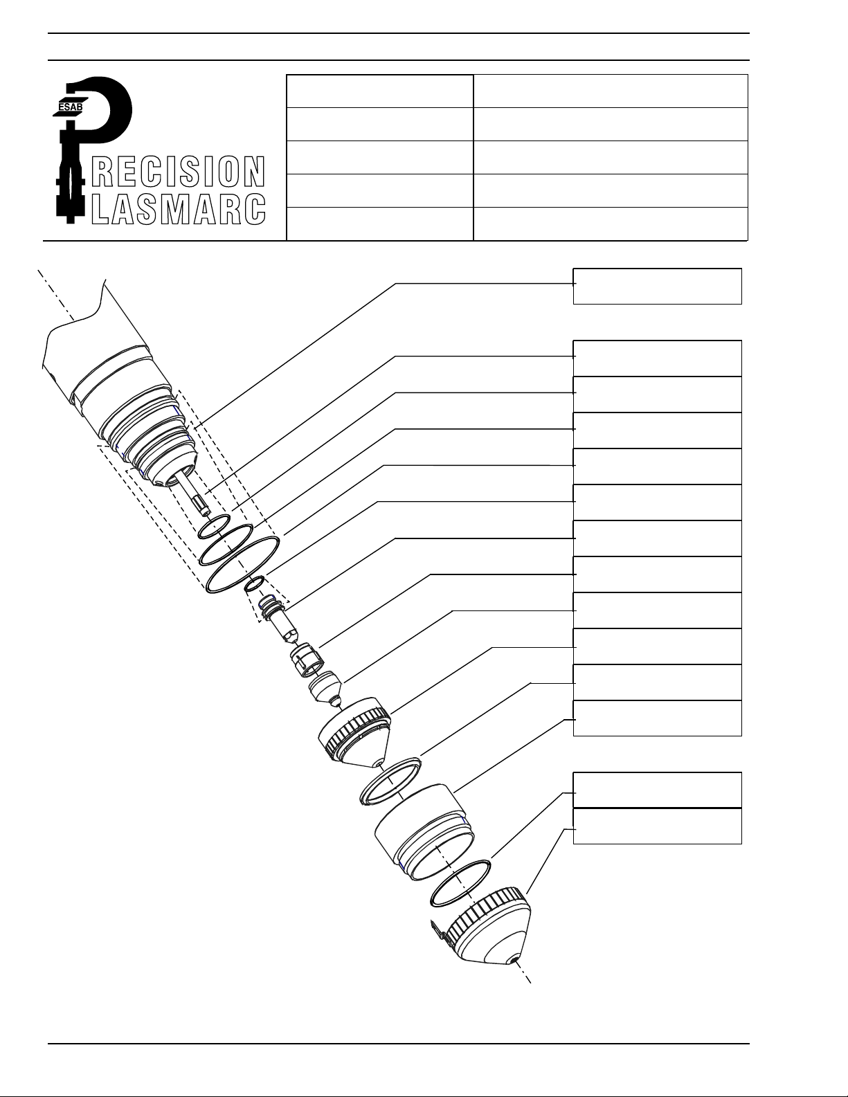
SECTION 4 OPERATION
(
)
)
PT-24 Torch
Material:
Amperes:
Plasm a Gas:
Shield Gas:
Shield Mix Gas:
Carbon Steel
100
Oxygen @ 125 PSI / 8.6 Bar
Nitrogen @ 125 PSI / 8.6 Bar
Oxygen @ 125 PSI / 8.6 Bar
Torch Body
Torch Body
Torch BodyTorch Body
P/N 21758
P/N 21758
P/N 21758P/N 21758
Water Baffle
Water Baffle
Water BaffleWater Ba ff le
P/N 21725
P/N 21725
P/N 21725P/N 21725
O-Ring
O-Ring
O-RingO-Ring
P/N 638797
P/N 638797
P/N 638797P/N 638797
O-Ring
O-Ring
O-RingO-Ring
P/N 86W62
P/N 86W62
P/N 86W62P/N 86W62
O-Ring
O-Ring
O-RingO-Ring
P/N 950714
P/N 950714
P/N 950714P/N 950714
O-Ring
O-Ring
O-RingO-Ring
P/N 98W18
P/N 98W18
P/N 98W18P/N 98W18
Electrode
Electrode
ElectrodeElectrode
P/N 21539
P/N 21539
P/N 21539P/N 21539
Swirl Baffle
Swirl Baffle
Swirl Baffle Swirl Baffle
P/N
P/N 21692 (4 holes)
21692 (4 holes)
21692 (4 holes
P/N P/N
21692
Nozzle
Nozzle
Nozzle Nozzle
P/N
P/N 21923, "E"
21923, "E"
P/N P/N
21923, "E"21923, "E"
Nozzle Retainer/D if fu ser
Nozzle Retainer/D if fu ser
Nozzle Retainer/D if fu serNozzle Retainer/D if fu ser
P/N 22007
P/N 22007
P/N 22007P/N 22007
Shield Cup Insulat or
Shield Cup Insulat or
Shield Cup Insulat orSh ield Cup Insu l a to r
P/N 22010
P/N 22010
P/N 22010P/N 22010
Insulator Shield Reta in er
Insulator Shield Reta in er
Insulator Shield Reta in erInsulat or Sh ie ld Reta in er
w/O-Ring P/N 21712
w/O-Ring P/N 21712
w/O-Ring P/N 21712w/O-Ring P/N 21712
4 holes
O-Ring
O-Ring - Shield
O-Ring O-Ring
(Ref. P/N 996528)
(Ref. P/N 996528)
(Ref. P/N 996528)(Ref. P/N 996528)
Cup shield w/Retainer
Cup shield w/Retainer
Cup shield w/RetainerCup shield w/Retainer
P/N 22531
P/N 22531
P/N 22531P/N 22531
Baffle and Nozzle
are the only two
replaceable torch
front-end parts that
may vary with
amperage
4-30
- Shield Retainer .
- Shield - Shield
Retainer .
Retainer .Retainer .
Page 65

SECTION 4 OPERATION
Process Data
Material Thickness
IN 0.312 0.375 0.500 0.625 0.750
MM 7,9 9,5 12,9 15,9 19,1
Pierce Delay (SEC.)
Setup Parameters (see notes)
Plasma Start Gas 1
Plasma Cut Gas 1
SG1-Start 6060606060
100 Amperes
Carbon Steel
PG
PG SG1
PGPG
O2 N2 O2
0 0 0.1 0.1 0.1
80 80 80 80 80
30 30 30 30 30
SG1 SG2
SG1SG1
SG2
SG2SG2
Shield Gas
(Flow Reading)
Flow Reading
SG1- Cut 3030303030
SG2- Cut Flow00000
Arc Voltage (standoff)
Travel Speed
IPM
MM/MIN
Notes:
1. Pilot Arc –HIGH.
2. Cut and ALT gas mix in Flow Control.
3. Float – Center of Ball
115 120 132 137 143
90 80 50 30 25
2290 2030 1270 760 630
4-31
Page 66

SECTION 4 OPERATION
(
)
)
PT-24 Torch
Material:
Amperes:
Plasm a Gas:
Shield Gas:
Shield Mix Gas:
Stainless Steel
30
Oxygen @ 125 PSI / 8.6 Bar
Nitrogen @ 125 PSI / 8.6 Bar
Oxygen @ 125 PSI / 8.6 Bar
Torch Body
Torch Body
Torch BodyTorch Body
P/N 21758
P/N 21758
P/N 21758P/N 21758
Water Baffle
Water Baffle
Water BaffleWater Ba ff le
P/N 21725
P/N 21725
P/N 21725P/N 21725
O-Ring
O-Ring
O-RingO-Ring
P/N 638797
P/N 638797
P/N 638797P/N 638797
O-Ring
O-Ring
O-RingO-Ring
P/N 86W62
P/N 86W62
P/N 86W62P/N 86W62
O-Ring
O-Ring
O-RingO-Ring
P/N 950714
P/N 950714
P/N 950714P/N 950714
O-Ring
O-Ring
O-RingO-Ring
P/N 98W18
P/N 98W18
P/N 98W18P/N 98W18
Electrode
Electrode
ElectrodeElectrode
P/N 21539
P/N 21539
P/N 21539P/N 21539
Swirl Baffle
Swirl Baffle
Swirl Baffle Swirl Baffle
P/N
P/N 21536 (3 holes)
21536 (3 holes)
21536 (3 holes
P/N P/N
21536
Nozzle
Nozzle
Nozzle Nozzle
P/N
P/N 21541, "B"
21541, "B"
P/N P/N
21541, "B"21541, "B"
Nozzle Retainer/D if fu ser
Nozzle Retainer/D if fu ser
Nozzle Retainer/D if fu serNozzle Retainer/D if fu ser
P/N 22007
P/N 22007
P/N 22007P/N 22007
Shield Cup Insulat or
Shield Cup Insulat or
Shield Cup Insulat orSh ield Cup Insu l a to r
P/N 22010
P/N 22010
P/N 22010P/N 22010
Insulator Shield Reta in er
Insulator Shield Reta in er
Insulator Shield Reta in erInsulat or Sh ie ld Reta in er
w/O-Ring P/N 21712
w/O-Ring P/N 21712
w/O-Ring P/N 21712w/O-Ring P/N 21712
3 holes
O-Ring
O-Ring - Shield
O-Ring O-Ring
(Ref. P/N 996528)
(Ref. P/N 996528)
(Ref. P/N 996528)(Ref. P/N 996528)
Cup shield w/Retainer
Cup shield w/Retainer
Cup shield w/RetainerCup shield w/Retainer
P/N 22531
P/N 22531
P/N 22531P/N 22531
Baffle and Nozzle
are the only two
replaceable torch
front-end parts that
may vary with
amperage
4-32
- Shield Retainer .
- Shield - Shield
Retainer .
Retainer .Retainer .
Page 67

SECTION 4 OPERATION
Process Data
Material Thickness
IN 26GA 24GA 22GA 18GA 16GA
MM 0,40,60,71,21,6
Pierce Delay (SEC.)
Setup Parameters (see notes)
Plasma Start Gas 1
Plasma Cut Gas 1
SG1-Start 4040404040
30 Amperes
Stainless Steel
PG
PG SG1
PGPG
O2 N2 O2
00000
45 45 45 45 45
18 18 18 18 18
SG1 SG2
SG1SG1
SG2
SG2SG2
Shield Gas
(Flow Reading)
Flow Reading
SG1- Cut 2020202020
SG2- Cut Flow55555
Arc Voltage (standoff)
Travel Speed
IPM
MM/MIN
Notes:
1. Pilot Arc –LOW.
2. Cut and ALT gas mix in Flow Control.
3. Float – Center of Ball
105 105 107 109 111
250 200 190 140 100
6350 5080 4826 3556 2540
4-33
Page 68

SECTION 4 OPERATION
(
)
)
PT-24 Torch
Material:
Amperes:
Plasm a Gas:
Shield Gas:
Shield Mix Gas:
Stainless Steel
50
Air @ 125 PSI / 8.6 Bar
Air @ 125 PSI / 8.6 Bar
Air @ 125 PSI / 8.6 Bar
Torch Body
Torch Body
Torch BodyTorch Body
P/N 21758
P/N 21758
P/N 21758P/N 21758
Water Baffle
Water Baffle
Water BaffleWater Ba ff le
P/N 21725
P/N 21725
P/N 21725P/N 21725
O-Ring
O-Ring
O-RingO-Ring
P/N 638797
P/N 638797
P/N 638797P/N 638797
O-Ring
O-Ring
O-RingO-Ring
P/N 86W62
P/N 86W62
P/N 86W62P/N 86W62
O-Ring
O-Ring
O-RingO-Ring
P/N 950714
P/N 950714
P/N 950714P/N 950714
O-Ring
O-Ring
O-RingO-Ring
P/N 98W18
P/N 98W18
P/N 98W18P/N 98W18
Electrode
Electrode
ElectrodeElectrode
P/N 21539
P/N 21539
P/N 21539P/N 21539
Swirl Baffle
Swirl Baffle
Swirl Baffle Swirl Baffle
P/N
P/N 21692 (4 holes)
21692 (4 holes)
21692 (4 holes
P/N P/N
21692
Nozzle
Nozzle
Nozzle Nozzle
P/N
P/N 21542, "C"
21542, "C"
P/N P/N
21542, "C"21542, "C"
Nozzle Retainer/D if fu ser
Nozzle Retainer/D if fu ser
Nozzle Retainer/D if fu serNozzle Retainer/D if fu ser
P/N 22007
P/N 22007
P/N 22007P/N 22007
Shield Cup Insulat or
Shield Cup Insulat or
Shield Cup Insulat orSh ield Cup Insu l a to r
P/N 22010
P/N 22010
P/N 22010P/N 22010
Insulator Shield Reta in er
Insulator Shield Reta in er
Insulator Shield Reta in erInsulat or Sh ie ld Reta in er
w/O-Ring P/N 21712
w/O-Ring P/N 21712
w/O-Ring P/N 21712w/O-Ring P/N 21712
4 holes
O-Ring
O-Ring - Shield
O-Ring O-Ring
(Ref. P/N 996528)
(Ref. P/N 996528)
(Ref. P/N 996528)(Ref. P/N 996528)
Cup shield w/Retainer
Cup shield w/Retainer
Cup shield w/RetainerCup shield w/Retainer
P/N 22531
P/N 22531
P/N 22531P/N 22531
Baffle and Nozzle
are the only two
replaceable torch
front-end parts that
may vary with
amperage
4-34
- Shield Retainer .
- Shield - Shield
Retainer .
Retainer .Retainer .
Page 69

SECTION 4 OPERATION
Process Data
Material Thickness
IN 0.125 0.187 0.250 0.375
MM 3,2 4,7 6,4 9,5
Pierce Delay (SEC.)
Setup Parameters (see notes)
Plasma Start Gas 1
Plasma Cut Gas 1
SG1-Start 45454545
50 Amperes
Stainless Steel
PG
PG SG1
PGPG
Air Air Air
0 0 01 0.2
60 60 60 60
95 95 95 95
SG1 SG2
SG1SG1
SG2
SG2SG2
Shield Gas
(Flow Reading)
Flow Reading
SG1- Cut 35353535
SG2- Cut Flow0000
Arc Voltage (standoff)
Travel Speed
IPM
MM/MIN
Notes:
1. Pilot Arc –HIGH.
2. Cut and ALT gas mix in Flow Control.
3. Float – Center of Ball
134 140 145 155
90 60 40 18
2286 1524 1016 457
4-35
Page 70

SECTION 4 OPERATION
(
)
)
PT-24 Torch
Material:
Amperes:
Plasm a Gas:
Shield Gas:
Shield Mix Gas:
Stainless Steel
70
Air @ 125 PSI / 8.6 Bar
Air @ 125 PSI / 8.6 Bar
Air @ 125 PSI / 8.6 Bar
Torch Body
Torch Body
Torch BodyTorch Body
P/N 21758
P/N 21758
P/N 21758P/N 21758
Water Baffle
Water Baffle
Water BaffleWater Ba ff le
P/N 21725
P/N 21725
P/N 21725P/N 21725
O-Ring
O-Ring
O-RingO-Ring
P/N 638797
P/N 638797
P/N 638797P/N 638797
O-Ring
O-Ring
O-RingO-Ring
P/N 86W62
P/N 86W62
P/N 86W62P/N 86W62
O-Ring
O-Ring
O-RingO-Ring
P/N 950714
P/N 950714
P/N 950714P/N 950714
O-Ring
O-Ring
O-RingO-Ring
P/N 98W18
P/N 98W18
P/N 98W18P/N 98W18
Electrode
Electrode
ElectrodeElectrode
P/N 21539
P/N 21539
P/N 21539P/N 21539
Swirl Baffle
Swirl Baffle
Swirl Baffle Swirl Baffle
P/N
P/N 21692 (4 holes)
21692 (4 holes)
21692 (4 holes
P/N P/N
21692
Nozzle
Nozzle
Nozzle Nozzle
P/N
P/N 21543, "D"
21543, "D"
P/N P/N
21543, "D"21543, "D"
Nozzle Retainer/D if fu ser
Nozzle Retainer/D if fu ser
Nozzle Retainer/D if fu serNozzle Retainer/D if fu ser
P/N 22007
P/N 22007
P/N 22007P/N 22007
Shield Cup Insulat or
Shield Cup Insulat or
Shield Cup Insulat orSh ield Cup Insu l a to r
P/N 22010
P/N 22010
P/N 22010P/N 22010
Insulator Shield Reta in er
Insulator Shield Reta in er
Insulator Shield Reta in erInsulat or Sh ie ld Reta in er
w/O-Ring P/N 21712
w/O-Ring P/N 21712
w/O-Ring P/N 21712w/O-Ring P/N 21712
4 holes
O-Ring
O-Ring - Shield
O-Ring O-Ring
(Ref. P/N 996528)
(Ref. P/N 996528)
(Ref. P/N 996528)(Ref. P/N 996528)
Cup shield w/Retainer
Cup shield w/Retainer
Cup shield w/RetainerCup shield w/Retainer
P/N 22531
P/N 22531
P/N 22531P/N 22531
Baffle and Nozzle
are the only two
replaceable torch
front-end parts that
may vary with
amperage
4-36
- Shield Retainer .
- Shield - Shield
Retainer .
Retainer .Retainer .
Page 71

SECTION 4 OPERATION
Process Data
Material Thickness
IN 0.187 0.250 0.375 0.500
MM 4,7 6,4 9,5 12,7
Pierce Delay (SEC.)
Setup Parameters (see notes)
Plasma Start Gas 1
Plasma Cut Gas 1
SG1-Start 60606060
70 Amperes
Stainless Steel
PG
PG SG1
PGPG
Air Air Air
0.3 0.4 0.5 0.6
70 70 70 70
95 95 95 95
SG1 SG2
SG1SG1
SG2
SG2SG2
Shield Gas
(Flow Reading)
Flow Reading
SG1- Cut 40404040
SG2- Cut Flow0000
Arc Voltage (standoff)
Travel Speed
IPM
MM/MIN
Notes:
1. Pilot Arc –HIGH.
2. Cut and ALT gas mix in Flow Control.
3. Float – Center of Ball
131 152 158 162
100 50 28 20
2540 1270 711 609
4-37
Page 72

SECTION 4 OPERATION
(
)
)
PT-24 Torch
Material:
Amperes:
Plasm a Gas:
Shield Gas:
Shield Mix Gas:
Stainless Steel
100
Air @ 125 PSI / 8.6 Bar
Air @ 125 PSI / 8.6 Bar
Air @ 125 PSI / 8.6 Bar
Torch Body
Torch Body
Torch BodyTorch Body
P/N 21758
P/N 21758
P/N 21758P/N 21758
Water Baffle
Water Baffle
Water BaffleWater Ba ff le
P/N 21725
P/N 21725
P/N 21725P/N 21725
O-Ring
O-Ring
O-RingO-Ring
P/N 638797
P/N 638797
P/N 638797P/N 638797
O-Ring
O-Ring
O-RingO-Ring
P/N 86W62
P/N 86W62
P/N 86W62P/N 86W62
O-Ring
O-Ring
O-RingO-Ring
P/N 950714
P/N 950714
P/N 950714P/N 950714
O-Ring
O-Ring
O-RingO-Ring
P/N 98W18
P/N 98W18
P/N 98W18P/N 98W18
Electrode
Electrode
ElectrodeElectrode
P/N 21539
P/N 21539
P/N 21539P/N 21539
Swirl Baffle
Swirl Baffle
Swirl Baffle Swirl Baffle
P/N
P/N 21692 (4 holes)
21692 (4 holes)
21692 (4 holes
P/N P/N
21692
Nozzle
Nozzle
Nozzle Nozzle
P/N
P/N 21923, "E"
21923, "E"
P/N P/N
21923, "E"21923, "E"
Nozzle Retainer/D if fu ser
Nozzle Retainer/D if fu ser
Nozzle Retainer/D if fu serNozzle Retainer/D if fu ser
P/N 22007
P/N 22007
P/N 22007P/N 22007
Shield Cup Insulat or
Shield Cup Insulat or
Shield Cup Insulat orSh ield Cup Insu l a to r
P/N 22010
P/N 22010
P/N 22010P/N 22010
Insulator Shield Reta in er
Insulator Shield Reta in er
Insulator Shield Reta in erInsulat or Sh ie ld Reta in er
w/O-Ring P/N 21712
w/O-Ring P/N 21712
w/O-Ring P/N 21712w/O-Ring P/N 21712
4 holes
O-Ring
O-Ring - Shield
O-Ring O-Ring
(Ref. P/N 996528)
(Ref. P/N 996528)
(Ref. P/N 996528)(Ref. P/N 996528)
Cup shield w/Retainer
Cup shield w/Retainer
Cup shield w/RetainerCup shield w/Retainer
P/N 22531
P/N 22531
P/N 22531P/N 22531
Baffle and Nozzle
are the only two
replaceable torch
front-end parts that
may vary with
amperage
4-38
- Shield Retainer .
- Shield - Shield
Retainer .
Retainer .Retainer .
Page 73

SECTION 4 OPERATION
Process Data
Material Thickness
IN 0.250 0.375 0.500 0.625
MM 6,4 9,5 12,7 15,9
Pierce Delay (SEC.)
Setup Parameters (see notes)
Plasma Start Gas 1
Plasma Cut Gas 1
SG1-Start 60606060
100 Amperes
Stainless Steel
PG
PG SG1
SG1 SG2
PGPG
SG1SG1
Air Air Air
0.3 0.4 0.5 0.6
80 80 80 80
65 65 65 70
SG2
SG2SG2
Shield Gas
(Flow Reading)
Flow Reading
SG1- Cut 35353540
SG2- Cut Flow0000
Arc Voltage (standoff)
Travel Speed
IPM
MM/MIN
Notes:
1. Pilot Arc –HIGH.
2. Cut and ALT gas mix in Flow Control.
3. Float – Center of Ball
129 135 142 150
80 60 35 25
2030 1520 889 635
4-39
Page 74

SECTION 4 OPERATION
(
)
)
PT-24 Torch
Material:
Amperes:
Plasm a Gas:
Shield Gas:
Shield Mix Gas:
Stainless Steel
70
Air @ 125 PSI / 8.6 Bar
Air @ 125 PSI / 8.6 Bar
Methane @ 100 PSI / 6.9 Bar
Torch Body
Torch Body
Torch BodyTorch Body
P/N 21758
P/N 21758
P/N 21758P/N 21758
Water Baffle
Water Baffle
Water BaffleWater Ba ff le
P/N 21725
P/N 21725
P/N 21725P/N 21725
O-Ring
O-Ring
O-RingO-Ring
P/N 638797
P/N 638797
P/N 638797P/N 638797
O-Ring
O-Ring
O-RingO-Ring
P/N 86W62
P/N 86W62
P/N 86W62P/N 86W62
O-Ring
O-Ring
O-RingO-Ring
P/N 950714
P/N 950714
P/N 950714P/N 950714
O-Ring
O-Ring
O-RingO-Ring
P/N 98W18
P/N 98W18
P/N 98W18P/N 98W18
Electrode
Electrode
ElectrodeElectrode
P/N 21539
P/N 21539
P/N 21539P/N 21539
Swirl Baffle
Swirl Baffle
Swirl Baffle Swirl Baffle
P/N
P/N 21692 (4 holes)
21692 (4 holes)
21692 (4 holes
P/N P/N
21692
Nozzle
Nozzle
Nozzle Nozzle
P/N
P/N 21543, "D"
21543, "D"
P/N P/N
21543, "D"21543, "D"
Nozzle Retainer/D if fu ser
Nozzle Retainer/D if fu ser
Nozzle Retainer/D if fu serNozzle Retainer/D if fu ser
P/N 22007
P/N 22007
P/N 22007P/N 22007
Shield Cup Insulat or
Shield Cup Insulat or
Shield Cup Insulat orSh ield Cup Insu l a to r
P/N 22010
P/N 22010
P/N 22010P/N 22010
Insulator Shield Reta in er
Insulator Shield Reta in er
Insulator Shield Reta in erInsulat or Sh ie ld Reta in er
w/O-Ring P/N 21712
w/O-Ring P/N 21712
w/O-Ring P/N 21712w/O-Ring P/N 21712
4 holes
O-Ring
O-Ring - Shield
O-Ring O-Ring
(Ref. P/N 996528)
(Ref. P/N 996528)
(Ref. P/N 996528)(Ref. P/N 996528)
Cup shield w/Retainer
Cup shield w/Retainer
Cup shield w/RetainerCup shield w/Retainer
P/N 22531
P/N 22531
P/N 22531P/N 22531
Baffle and Nozzle
are the only two
replaceable torch
front-end parts that
may vary with
amperage
4-40
- Shield Retainer .
- Shield - Shield
Retainer .
Retainer .Retainer .
Page 75

SECTION 4 OPERATION
Process Data
Material Thickness
IN 0.125 0.187 0.250 0.387 0.500
MM 3,2 4,7 6,4 9,5 12,7
Pierce Delay (SEC.)
Setup Parameters (see notes)
Plasma Start Gas 1
Plasma Cut Gas 1
SG1-Start 6060606060
70 Amperes
Stainless Steel
PG
PG SG1
PGPG
Air Air CH4
0.20.30.40.50.6
70 70 70 70 70
100 100 100 100 100
SG1 SG2
SG1SG1
SG2
SG2SG2
Shield Gas
(Flow Reading)
Flow Reading
SG1- Cut 4040404040
SG2- Cut Flow 10 10 10 10 10
Arc Voltage (standoff)
Travel Speed
IPM
MM/MIN
Notes:
1. Pilot Arc –HIGH.
2. Cut and ALT gas mix in Flow Control.
3. Float – Center of Ball
131 146 154 166 175
12080503024
3048 2032 1270 762 609
4-41
Page 76

SECTION 4 OPERATION
(
)
)
PT-24 Torch
Material:
Amperes:
Plasm a Gas:
Shield Gas:
Shield Mix Gas:
Stainless Steel
100
Air @ 125 PSI / 8.6 Bar
Air @ 125 PSI / 8.6 Bar
Methane @ 100 PSI / 6.9 Bar
Torch Body
Torch Body
Torch BodyTorch Body
P/N 21758
P/N 21758
P/N 21758P/N 21758
Water Baffle
Water Baffle
Water BaffleWater Ba ff le
P/N 21725
P/N 21725
P/N 21725P/N 21725
O-Ring
O-Ring
O-RingO-Ring
P/N 638797
P/N 638797
P/N 638797P/N 638797
O-Ring
O-Ring
O-RingO-Ring
P/N 86W62
P/N 86W62
P/N 86W62P/N 86W62
O-Ring
O-Ring
O-RingO-Ring
P/N 950714
P/N 950714
P/N 950714P/N 950714
O-Ring
O-Ring
O-RingO-Ring
P/N 98W18
P/N 98W18
P/N 98W18P/N 98W18
Electrode
Electrode
ElectrodeElectrode
P/N 21539
P/N 21539
P/N 21539P/N 21539
Swirl Baffle
Swirl Baffle
Swirl Baffle Swirl Baffle
P/N
P/N 21692 (4 holes)
21692 (4 holes)
21692 (4 holes
P/N P/N
21692
Nozzle
Nozzle
Nozzle Nozzle
P/N
P/N 21923, "E"
21923, "E"
P/N P/N
21923, "E"21923, "E"
Nozzle Retainer/D if fu ser
Nozzle Retainer/D if fu ser
Nozzle Retainer/D if fu serNozzle Retainer/D if fu ser
P/N 22007
P/N 22007
P/N 22007P/N 22007
Shield Cup Insulat or
Shield Cup Insulat or
Shield Cup Insulat orSh ield Cup Insu l a to r
P/N 22010
P/N 22010
P/N 22010P/N 22010
Insulator Shield Reta in er
Insulator Shield Reta in er
Insulator Shield Reta in erInsulat or Sh ie ld Reta in er
w/O-Ring P/N 21712
w/O-Ring P/N 21712
w/O-Ring P/N 21712w/O-Ring P/N 21712
4 holes
O-Ring
O-Ring - Shield
O-Ring O-Ring
(Ref. P/N 996528)
(Ref. P/N 996528)
(Ref. P/N 996528)(Ref. P/N 996528)
Cup shield w/Retainer
Cup shield w/Retainer
Cup shield w/RetainerCup shield w/Retainer
P/N 22531
P/N 22531
P/N 22531P/N 22531
Baffle and Nozzle
are the only two
replaceable torch
front-end parts that
may vary with
amperage
4-42
- Shield Retainer .
- Shield - Shield
Retainer .
Retainer .Retainer .
Page 77

SECTION 4 OPERATION
Process Data
Material Thickness
IN 0.250 0.375 0.500 0.625
MM 6,4 9,5 12,7 15,9
Pierce Delay (SEC.)
Setup Parameters (see notes)
Plasma Start Gas 1
Plasma Cut Gas 1
SG1-Start 60606060
100 Amperes
Stainless Steel
PG
PG SG1
PGPG
Air Air CH4
0.3 0.4 0.5 0.6
80 80 80 80
100 100 100 100
SG1 SG2
SG1SG1
SG2
SG2SG2
Shield Gas
(Flow Reading)
Flow Reading
SG1- Cut 40404040
SG2- Cut Flow 7 10 10 10
Arc Voltage (standoff)
Travel Speed
IPM
MM/MIN
Notes:
1. Pilot Arc –HIGH.
2. Cut and ALT gas mix in Flow Control.
3. Float – Center of Ball
140 150 159 170
80 60 35 25
2030 1524 889 635
4-43
Page 78

SECTION 4 OPERATION
(
)
)
PT-24 Torch
Material:
Amperes:
Plasm a Gas:
Shield Gas:
Shield Mix Gas:
Stainless Steel
50
Nitrogen @ 125 PSI / 8.6 Bar
Nitrogen @ 125 PSI / 8.6 Bar
Torch Body
Torch Body
Torch BodyTorch Body
P/N 21758
P/N 21758
P/N 21758P/N 21758
Water Baffle
Water Baffle
Water BaffleWater Ba ff le
P/N 21725
P/N 21725
P/N 21725P/N 21725
O-Ring
O-Ring
O-RingO-Ring
P/N 638797
P/N 638797
P/N 638797P/N 638797
O-Ring
O-Ring
O-RingO-Ring
P/N 86W62
P/N 86W62
P/N 86W62P/N 86W62
O-Ring
O-Ring
O-RingO-Ring
P/N 950714
P/N 950714
P/N 950714P/N 950714
O-Ring
O-Ring
O-RingO-Ring
P/N 98W18
P/N 98W18
P/N 98W18P/N 98W18
Electrode
Electrode
ElectrodeElectrode
P/N 21539
P/N 21539
P/N 21539P/N 21539
Swirl Baffle
Swirl Baffle
Swirl Baffle Swirl Baffle
P/N
P/N 21692 (4 holes)
21692 (4 holes)
21692 (4 holes
P/N P/N
21692
Nozzle
Nozzle
Nozzle Nozzle
P/N
P/N 21542, "C"
21542, "C"
P/N P/N
21542, "C"21542, "C"
Nozzle Retainer/D if fu ser
Nozzle Retainer/D if fu ser
Nozzle Retainer/D if fu serNozzle Retainer/D if fu ser
P/N 22007
P/N 22007
P/N 22007P/N 22007
Shield Cup Insulat or
Shield Cup Insulat or
Shield Cup Insulat orSh ield Cup Insu l a to r
P/N 22010
P/N 22010
P/N 22010P/N 22010
Insulator Shield Reta in er
Insulator Shield Reta in er
Insulator Shield Reta in erInsulat or Sh ie ld Reta in er
w/O-Ring P/N 21712
w/O-Ring P/N 21712
w/O-Ring P/N 21712w/O-Ring P/N 21712
4 holes
O-Ring
O-Ring - Shield
O-Ring O-Ring
(Ref. P/N 996528)
(Ref. P/N 996528)
(Ref. P/N 996528)(Ref. P/N 996528)
Cup shield w/Retainer
Cup shield w/Retainer
Cup shield w/RetainerCup shield w/Retainer
P/N 22531
P/N 22531
P/N 22531P/N 22531
Baffle and Nozzle
are the only two
replaceable torch
front-end parts that
may vary with
amperage
4-44
- Shield Retainer .
- Shield - Shield
Retainer .
Retainer .Retainer .
Page 79

SECTION 4 OPERATION
Process Data
Material Thickness
IN 0.125 0.187 0.250 0.375
MM 3,2 4,7 6,4 9,5
Pierce Delay (SEC.)
Setup Parameters (see notes)
Plasma Start Gas 1
Plasma Cut Gas 1
SG1-Start 45454545
50 Amperes
Stainless Steel
PG
PG SG1
PGPG
N2 N2
0 0 0.1 0.2
60 60 60 60
85 85 85 85
SG1 SG2
SG1SG1
SG2
SG2SG2
Shield Gas
(Flow Reading)
Flow Reading
SG1- Cut 35353535
SG2- Cut Flow0000
Arc Voltage (standoff)
Travel Speed
IPM
MM/MIN
Notes:
1. Pilot Arc –HIGH.
2. Cut and ALT gas mix in Flow Control.
3. Float – Center of Ball
128 133 144 155
90 60 40 22
2286 1524 1016 558
4-45
Page 80

SECTION 4 OPERATION
(
)
)
PT-24 Torch
Material:
Amperes:
Plasm a Gas:
Shield Gas:
Shield Mix Gas:
Stainless Steel
70
Nitrogen @ 125 PSI / 8.6 Bar
Nitrogen @ 125 PSI / 8.6 Bar
Torch Body
Torch Body
Torch BodyTorch Body
P/N 21758
P/N 21758
P/N 21758P/N 21758
Water Baffle
Water Baffle
Water BaffleWater Ba ff le
P/N 21725
P/N 21725
P/N 21725P/N 21725
O-Ring
O-Ring
O-RingO-Ring
P/N 638797
P/N 638797
P/N 638797P/N 638797
O-Ring
O-Ring
O-RingO-Ring
P/N 86W62
P/N 86W62
P/N 86W62P/N 86W62
O-Ring
O-Ring
O-RingO-Ring
P/N 950714
P/N 950714
P/N 950714P/N 950714
O-Ring
O-Ring
O-RingO-Ring
P/N 98W18
P/N 98W18
P/N 98W18P/N 98W18
Electrode
Electrode
ElectrodeElectrode
P/N 21539
P/N 21539
P/N 21539P/N 21539
Swirl Baffle
Swirl Baffle
Swirl Baffle Swirl Baffle
P/N
P/N 21692 (4 holes)
21692 (4 holes)
21692 (4 holes
P/N P/N
21692
Nozzle
Nozzle
Nozzle Nozzle
P/N
P/N 21543, "D"
21543, "D"
P/N P/N
21543, "D"21543, "D"
Nozzle Retainer/D if fu ser
Nozzle Retainer/D if fu ser
Nozzle Retainer/D if fu serNozzle Retainer/D if fu ser
P/N 22007
P/N 22007
P/N 22007P/N 22007
Shield Cup Insulat or
Shield Cup Insulat or
Shield Cup Insulat orSh ield Cup Insu l a to r
P/N 22010
P/N 22010
P/N 22010P/N 22010
Insulator Shield Reta in er
Insulator Shield Reta in er
Insulator Shield Reta in erInsulat or Sh ie ld Reta in er
w/O-Ring P/N 21712
w/O-Ring P/N 21712
w/O-Ring P/N 21712w/O-Ring P/N 21712
4 holes
O-Ring
O-Ring - Shield
O-Ring O-Ring
(Ref. P/N 996528)
(Ref. P/N 996528)
(Ref. P/N 996528)(Ref. P/N 996528)
Cup shield w/Retainer
Cup shield w/Retainer
Cup shield w/RetainerCup shield w/Retainer
P/N 22531
P/N 22531
P/N 22531P/N 22531
Baffle and Nozzle
are the only two
replaceable torch
front-end parts that
may vary with
amperage
4-46
- Shield Retainer .
- Shield - Shield
Retainer .
Retainer .Retainer .
Page 81

SECTION 4 OPERATION
Process Data
Material Thickness
IN 0.187 0.250 0.375 0.500
MM 4,7 6,4 9,5 12,7
Pierce Delay (SEC.)
Setup Parameters (see notes)
Plasma Start Gas 1
Plasma Cut Gas 1
SG1-Start 60606060
70 Amperes
Stainless Steel
PG
PG SG1
PGPG
N2 N2
0.3 0.4 0.5 0.6
70 70 70 70
95 95 95 95
SG1 SG2
SG1SG1
SG2
SG2SG2
Shield Gas
(Flow Reading)
Flow Reading
SG1- Cut 40404040
SG2- Cut Flow0000
Arc Voltage (standoff)
Travel Speed
IPM
MM/MIN
Notes:
1. Pilot Arc –HIGH.
2. Cut and ALT gas mix in Flow Control.
3. Float – Center of Ball
132 150 154 159
75 50 28 24
1905 1270 711 609
4-47
Page 82

SECTION 4 OPERATION
(
)
)
PT-24 Torch
Material:
Amperes:
Plasm a Gas:
Shield Gas:
Shield Mix Gas:
Stainless Steel
100
Nitrogen @ 125 PSI / 8.6 Bar
Nitrogen @ 125 PSI / 8.6 Bar
Torch Body
Torch Body
Torch BodyTorch Body
P/N 21758
P/N 21758
P/N 21758P/N 21758
Water Baffle
Water Baffle
Water BaffleWater Ba ff le
P/N 21725
P/N 21725
P/N 21725P/N 21725
O-Ring
O-Ring
O-RingO-Ring
P/N 638797
P/N 638797
P/N 638797P/N 638797
O-Ring
O-Ring
O-RingO-Ring
P/N 86W62
P/N 86W62
P/N 86W62P/N 86W62
O-Ring
O-Ring
O-RingO-Ring
P/N 950714
P/N 950714
P/N 950714P/N 950714
O-Ring
O-Ring
O-RingO-Ring
P/N 98W18
P/N 98W18
P/N 98W18P/N 98W18
Electrode
Electrode
ElectrodeElectrode
P/N 21539
P/N 21539
P/N 21539P/N 21539
Swirl Baffle
Swirl Baffle
Swirl Baffle Swirl Baffle
P/N
P/N 21692 (4 holes)
21692 (4 holes)
21692 (4 holes
P/N P/N
21692
Nozzle
Nozzle
Nozzle Nozzle
P/N
P/N 21923, "E"
21923, "E"
P/N P/N
21923, "E"21923, "E"
Nozzle Retainer/D if fu ser
Nozzle Retainer/D if fu ser
Nozzle Retainer/D if fu serNozzle Retainer/D if fu ser
P/N 22007
P/N 22007
P/N 22007P/N 22007
Shield Cup Insulat or
Shield Cup Insulat or
Shield Cup Insulat orSh ield Cup Insu l a to r
P/N 22010
P/N 22010
P/N 22010P/N 22010
Insulator Shield Reta in er
Insulator Shield Reta in er
Insulator Shield Reta in erInsulat or Sh ie ld Reta in er
w/O-Ring P/N 21712
w/O-Ring P/N 21712
w/O-Ring P/N 21712w/O-Ring P/N 21712
4 holes
O-Ring
O-Ring - Shield
O-Ring O-Ring
(Ref. P/N 996528)
(Ref. P/N 996528)
(Ref. P/N 996528)(Ref. P/N 996528)
Cup shield w/Retainer
Cup shield w/Retainer
Cup shield w/RetainerCup shield w/Retainer
P/N 22531
P/N 22531
P/N 22531P/N 22531
Baffle and Nozzle
are the only two
replaceable torch
front-end parts that
may vary with
amperage
4-48
- Shield Retainer .
- Shield - Shield
Retainer .
Retainer .Retainer .
Page 83

SECTION 4 OPERATION
Process Data
Material Thickness
IN 0.250 0.375 0.500 0.625
MM 6,4 9,5 12,7 15,9
Pierce Delay (SEC.)
Setup Parameters (see notes)
Plasma Start Gas 1
Plasma Cut Gas 1
SG1-Start 60606060
100 Amperes
Stainless Steel
PG
PG SG1
PGPG
N2 N2
0.3 0.4 0.5 0.6
80 80 80 80
95 95 95 95
SG1 SG2
SG1SG1
SG2
SG2SG2
Shield Gas
(Flow Reading)
Flow Reading
SG1- Cut 50353535
SG2- Cut Flow0000
Arc Voltage (standoff)
Travel Speed
IPM
MM/MIN
Notes:
1. Pilot Arc –HIGH.
2. Cut and ALT gas mix in Flow Control.
3. Float – Center of Ball
135 145 153 157
80 60 35 25
2032 1520 889 635
4-49
Page 84

SECTION 4 OPERATION
(
)
)
PT-24 Torch
Material:
Amperes:
Plasm a Gas:
Shield Gas:
Shield Mix Gas:
Stainless Steel
70
Nitrogen @ 125 PSI / 8.6 Bar
Nitrogen @ 125 PSI / 8.6 Bar
Methane @ 100 PSI / 6.9 Bar
Torch Body
Torch Body
Torch BodyTorch Body
P/N 21758
P/N 21758
P/N 21758P/N 21758
Water Baffle
Water Baffle
Water BaffleWater Ba ff le
P/N 21725
P/N 21725
P/N 21725P/N 21725
O-Ring
O-Ring
O-RingO-Ring
P/N 638797
P/N 638797
P/N 638797P/N 638797
O-Ring
O-Ring
O-RingO-Ring
P/N 86W62
P/N 86W62
P/N 86W62P/N 86W62
O-Ring
O-Ring
O-RingO-Ring
P/N 950714
P/N 950714
P/N 950714P/N 950714
O-Ring
O-Ring
O-RingO-Ring
P/N 98W18
P/N 98W18
P/N 98W18P/N 98W18
Electrode
Electrode
ElectrodeElectrode
P/N 21539
P/N 21539
P/N 21539P/N 21539
Swirl Baffle
Swirl Baffle
Swirl Baffle Swirl Baffle
P/N
P/N 21692 (4 holes)
21692 (4 holes)
21692 (4 holes
P/N P/N
21692
Nozzle
Nozzle
Nozzle Nozzle
P/N
P/N 21543, "D"
21543, "D"
P/N P/N
21543, "D"21543, "D"
Nozzle Retainer/D if fu ser
Nozzle Retainer/D if fu ser
Nozzle Retainer/D if fu serNozzle Retainer/D if fu ser
P/N 22007
P/N 22007
P/N 22007P/N 22007
Shield Cup Insulat or
Shield Cup Insulat or
Shield Cup Insulat orSh ield Cup Insu l a to r
P/N 22010
P/N 22010
P/N 22010P/N 22010
Insulator Shield Reta in er
Insulator Shield Reta in er
Insulator Shield Reta in erInsulat or Sh ie ld Reta in er
w/O-Ring P/N 21712
w/O-Ring P/N 21712
w/O-Ring P/N 21712w/O-Ring P/N 21712
4 holes
O-Ring
O-Ring - Shield
O-Ring O-Ring
(Ref. P/N 996528)
(Ref. P/N 996528)
(Ref. P/N 996528)(Ref. P/N 996528)
Cup shield w/Retainer
Cup shield w/Retainer
Cup shield w/RetainerCup shield w/Retainer
P/N 22531
P/N 22531
P/N 22531P/N 22531
Baffle and Nozzle
are the only two
replaceable torch
front-end parts that
may vary with
amperage
4-50
- Shield Retainer .
- Shield - Shield
Retainer .
Retainer .Retainer .
Page 85

SECTION 4 OPERATION
Process Data
Material Thickness
IN 0.187 0.250 0.375 0.500
MM 4,7 6,4 9,5 12,7
Pierce Delay (SEC.)
Setup Parameters (see notes)
Plasma Start Gas 1
Plasma Cut Gas 1
SG1-Start 60606060
70 Amperes
Stainless Steel
PG
PG SG1
PGPG
N2 N2 CH4
0.3 0.4 0.5 0.6
75 75 75 75
85 85 85 85
SG1 SG2
SG1SG1
SG2
SG2SG2
Shield Gas
(Flow Reading)
Flow Reading
SG1- Cut 43434343
SG2- Cut Flow5555
Arc Voltage (standoff)
Travel Speed
IPM
MM/MIN
Notes:
1. Pilot Arc –HIGH.
2. Cut and ALT gas mix in Flow Control.
3. Float – Center of Ball
136 150 159 162
75 50 28 24
1905 1270 711 609
4-51
Page 86

SECTION 4 OPERATION
(
)
)
PT-24 Torch
Material:
Amperes:
Plasm a Gas:
Shield Gas:
Shield Mix Gas:
Stainless Steel
100
Nitrogen @ 125 PSI / 8.6 Bar
Nitrogen @ 125 PSI / 8.6 Bar
Methane @ 100 PSI / 6.9 Bar
Torch Body
Torch Body
Torch BodyTorch Body
P/N 21758
P/N 21758
P/N 21758P/N 21758
Water Baffle
Water Baffle
Water BaffleWater Ba ff le
P/N 21725
P/N 21725
P/N 21725P/N 21725
O-Ring
O-Ring
O-RingO-Ring
P/N 638797
P/N 638797
P/N 638797P/N 638797
O-Ring
O-Ring
O-RingO-Ring
P/N 86W62
P/N 86W62
P/N 86W62P/N 86W62
O-Ring
O-Ring
O-RingO-Ring
P/N 950714
P/N 950714
P/N 950714P/N 950714
O-Ring
O-Ring
O-RingO-Ring
P/N 98W18
P/N 98W18
P/N 98W18P/N 98W18
Electrode
Electrode
ElectrodeElectrode
P/N 21539
P/N 21539
P/N 21539P/N 21539
Swirl Baffle
Swirl Baffle
Swirl BaffleSwirl Baffle
P/N
P/N 21692 (4 holes)
21692 (4 holes)
21692 (4 holes
P/N P/N
21692
Nozzle
Nozzle
NozzleNozzle
P/N
P/N 21923, "E"
21923, "E"
P/N P/N
21923, "E"21923, "E"
Nozzle Retainer/D if fu ser
Nozzle Retainer/D if fu ser
Nozzle Retainer/D if fu serNozzle Retainer/D if fu ser
P/N 22007
P/N 22007
P/N 22007P/N 22007
Shield Cup Insulat or
Shield Cup Insulat or
Shield Cup Insulat orSh ield Cup Insu l a to r
P/N 22010
P/N 22010
P/N 22010P/N 22010
Insulator Shield Reta in er
Insulator Shield Reta in er
Insulator Shield Reta in erInsulat or Sh ie ld Reta in er
w/O-Ring P/N 21712
w/O-Ring P/N 21712
w/O-Ring P/N 21712w/O-Ring P/N 21712
4 holes
O-Ring
O-Ring - Shield
O-Ring O-Ring
(Ref. P/N 996528)
(Ref. P/N 996528)
(Ref. P/N 996528)(Ref. P/N 996528)
Cup shield w/Retainer
Cup shield w/Retainer
Cup shield w/RetainerCup shield w/Retainer
P/N 22531
P/N 22531
P/N 22531P/N 22531
4-52
- Shield Retainer .
- Shield - Shield
Baffle and Nozzle
are the only two
replaceable torch
front-end parts that
may vary with
amperage
Retainer .
Retainer .Retainer .
Page 87

SECTION 4 OPERATION
Process Data
Material Thickness
IN 0.250 0.375 0.500 0.625
MM 6,4 9,5 12,7 5,9
Pierce Delay (SEC.)
Setup Parameters (see notes)
Plasma Start Gas 1
Plasma Cut Gas 1
SG1-Start 50706042
100 Amperes
Stainless Steel
PG
PG SG1
PGPG
N2 N2 CH4
0.3 0.4 0.5 0.6
80 80 80 80
95 95 95 95
SG1 SG2
SG1SG1
SG2
SG2SG2
Shield Gas
(Flow Reading)
Flow Reading
SG1- Cut 45454542
SG2- Cut Flow5557
Arc Voltage (standoff)
Travel Speed
IPM
MM/MIN
Notes:
1. Pilot Arc –HIGH.
2. Cut and ALT gas mix in Flow Control.
3. Float – Center of Ball
138 150 162 170
80 60 35 25
2032 1524 889 635
4-53
Page 88

SECTION 4 OPERATION
(
)
)
Plasma Marking “B” Nozzle
PT-24 Torch
Amperes:
Plasm a Gas:
Shield Gas:
10
Argon @ 125 PSI / 8.6 Bar
Air @ 125 PSI/ 8.6 Bar
Torch Body
Torch Body
Torch BodyTorch Body
P/N 21758
P/N 21758
P/N 21758P/N 21758
Water Baffle
Water Baffle
Water BaffleWater Ba ff le
P/N 21725
P/N 21725
P/N 21725P/N 21725
O-Ring
O-Ring
O-RingO-Ring
P/N 638797
P/N 638797
P/N 638797P/N 638797
O-Ring
O-Ring
O-RingO-Ring
P/N 86W62
P/N 86W62
P/N 86W62P/N 86W62
O-Ring
O-Ring
O-RingO-Ring
P/N 950714
P/N 950714
P/N 950714P/N 950714
O-Ring
O-Ring
O-RingO-Ring
P/N 98W18
P/N 98W18
P/N 98W18P/N 98W18
Electrode
Electrode
ElectrodeElectrode
P/N 21539
P/N 21539
P/N 21539P/N 21539
Swirl Baffle
Swirl Baffle
Swirl BaffleSwirl Baffle
P/N 21536 (3 Holes)
P/N 21536 (3 Holes)
P/N 21536 (3 Holes
P/N 21536
Nozzle
Nozzle
NozzleNozzle
P/N 21541 “B”
P/N 21541 “B”
P/N 21541 “B”P/N 21541 “B”
Nozzle Retainer/D if fu ser
Nozzle Retainer/D if fu ser
Nozzle Retainer/D if fu serNozzle Retainer/D if fu ser
P/N 22007
P/N 22007
P/N 22007P/N 22007
Shield Cup Insulat or
Shield Cup Insulat or
Shield Cup Insulat orSh ield Cup Insu l a to r
P/N 22010
P/N 22010
P/N 22010P/N 22010
Insulator Shield Reta in er
Insulator Shield Reta in er
Insulator Shield Reta in erInsulat or Sh ie ld Reta in er
w/O-Ring P/N 21712
w/O-Ring P/N 21712
w/O-Ring P/N 21712w/O-Ring P/N 21712
3 Holes
O-Ring
O-Ring - Shield
O-Ring O-Ring
(Ref. P/N 996528)
(Ref. P/N 996528)
(Ref. P/N 996528)(Ref. P/N 996528)
Cup shield w/Retainer
Cup shield w/Retainer
Cup shield w/RetainerCup shield w/Retainer
P/N 22531
P/N 22531
P/N 22531P/N 22531
4-54
- Shield Retainer .
- Shield - Shield
Baffle and Nozzle
are the only two
replaceable torch
front-end parts that
may vary with
amperage
Retainer .
Retainer .Retainer .
Page 89

SECTION 4 OPERATION
Plasma Marking
Process Data
Setup Parameters (see notes)
Plasma Start Gas 1
Plasma Cut Gas 1
SG1-Start 35
Shield Gas
(Flow Reading)
Flow Reading
SG1- Cut 35
SG2- Cu t Flow 0
“B” Nozzle
10 Amperes
35
35
Arc Voltage (standoff)
Travel Speed
IPM
MM/MIN
Notes:
1. Pilot Arc –HIGH.
2. Cut and ALT gas mix in Flow Control.
3. Float – Center of Ball
77
200
5080
4-55
Page 90

SECTION 4 OPERATION
Plasma Marking “B” Nozzle
PT-24 Torch
Amperes:
Plasm a Gas:
Shield Gas:
15
Argon @ 125 PSI / 8.6 Bar
Air @ 125 PSI/ 8.6 Bar
Torch Body
Torch Body
Torch BodyTorch Body
P/N 21758
P/N 21758
P/N 21758P/N 21758
Water Baffle
Water Baffle
Water BaffleWater Ba ff le
P/N 21725
P/N 21725
P/N 21725P/N 21725
O-Ring
O-Ring
O-RingO-Ring
P/N 638797
P/N 638797
P/N 638797P/N 638797
O-Ring
O-Ring
O-RingO-Ring
P/N 86W62
P/N 86W62
P/N 86W62P/N 86W62
O-Ring
O-Ring
O-RingO-Ring
P/N 950714
P/N 950714
P/N 950714P/N 950714
O-Ring
O-Ring
O-RingO-Ring
P/N 98W18
P/N 98W18
P/N 98W18P/N 98W18
Electrode
Electrode
ElectrodeElectrode
P/N 21539
P/N 21539
P/N 21539P/N 21539
Swirl Baffle
Swirl Baffle
Swirl BaffleSwirl Baffle
P/N 21536 3 holes
P/N 21536 3 holes
P/N 21536 3 holesP/N 21536 3 holes
Nozzle
Nozzle
NozzleNozzle
P/N 21541 “B”
P/N 21541 “B”
P/N 21541 “B”P/N 21541 “B”
Nozzle Retainer/D if fu ser
Nozzle Retainer/D if fu ser
Nozzle Retainer/D if fu serNozzle Retainer/D if fu ser
P/N 22007
P/N 22007
P/N 22007P/N 22007
Shield Cup Insulat or
Shield Cup Insulat or
Shield Cup Insulat orSh ield Cup Insu l a to r
P/N 22010
P/N 22010
P/N 22010P/N 22010
Insulator Shield Reta in er
Insulator Shield Reta in er
Insulator Shield Reta in erInsulat or Sh ie ld Reta in er
w/O-Ring P/N 21712
w/O-Ring P/N 21712
w/O-Ring P/N 21712w/O-Ring P/N 21712
4-56
O-Ring
O-Ring - Shield
O-Ring O-Ring
(Ref. P/N 996528)
(Ref. P/N 996528)
(Ref. P/N 996528)(Ref. P/N 996528)
Cup shield w/Retainer
Cup shield w/Retainer
Cup shield w/RetainerCup shield w/Retainer
P/N 22531
P/N 22531
P/N 22531P/N 22531
- Shield Retainer .
- Shield - Shield
Baffle and Nozzle
are the only two
replaceable torch
front-end parts that
may vary with
amperage
Retainer .
Retainer .Retainer .
Page 91

SECTION 4 OPERATION
Plasma Marking
Process Data
Setup Parameters (see notes)
Plasma Start Gas 1
Plasma Cut Gas 1
SG1-Start 35
Shield Gas
(Flow Reading)
Flow Reading
SG1- Cut 35
SG2- Cu t Flow 0
“B” Nozzle
15 Amperes
35
35
Arc Voltage (standoff)
Travel Speed
IPM
MM/MIN
Notes:
1. Pilot Arc –HIGH.
2. Cut and ALT gas mix in Flow Control.
3. Float – Center of Ball
77
300
7620
4-57
Page 92

SECTION 4 OPERATION
(
)
)
Plasma Marking “C” Nozzle
PT-24 Torch
Amperes:
Plasm a Gas:
Shield Gas:
10
Argon @ 125 PSI / 8.6 Bar
Air @ 125 PSI/ 8.6 Bar
Torch Body
Torch Body
Torch BodyTorch Body
P/N 21758
P/N 21758
P/N 21758P/N 21758
Water Baffle
Water Baffle
Water BaffleWater Ba ff le
P/N 21725
P/N 21725
P/N 21725P/N 21725
O-Ring
O-Ring
O-RingO-Ring
P/N 638797
P/N 638797
P/N 638797P/N 638797
O-Ring
O-Ring
O-RingO-Ring
P/N 86W62
P/N 86W62
P/N 86W62P/N 86W62
O-Ring
O-Ring
O-RingO-Ring
P/N 950714
P/N 950714
P/N 950714P/N 950714
O-Ring
O-Ring
O-RingO-Ring
P/N 98W18
P/N 98W18
P/N 98W18P/N 98W18
Electrode
Electrode
ElectrodeElectrode
P/N 21539
P/N 21539
P/N 21539P/N 21539
Swirl Baffle
Swirl Baffle
Swirl BaffleSwirl Baffle
P/N
P/N 21692 (4 holes)
21692 (4 holes)
21692 (4 holes
P/N P/N
21692
Nozzle
Nozzle
NozzleNozzle
P/N 21542 “C”
P/N 21542 “C”
P/N 21542 “C”P/N 21542 “C”
Nozzle Retainer/D if fu ser
Nozzle Retainer/D if fu ser
Nozzle Retainer/D if fu serNozzle Retainer/D if fu ser
P/N 22007
P/N 22007
P/N 22007P/N 22007
Shield Cup Insulat or
Shield Cup Insulat or
Shield Cup Insulat orSh ield Cup Insu l a to r
P/N 22010
P/N 22010
P/N 22010P/N 22010
Insulator Shield Reta in er
Insulator Shield Reta in er
Insulator Shield Reta in erInsulat or Sh ie ld Reta in er
w/O-Ring P/N 21712
w/O-Ring P/N 21712
w/O-Ring P/N 21712w/O-Ring P/N 21712
4 holes
O-Ring
O-Ring - Shield
O-Ring O-Ring
(Ref. P/N 996528)
(Ref. P/N 996528)
(Ref. P/N 996528)(Ref. P/N 996528)
Cup shield w/Retainer
Cup shield w/Retainer
Cup shield w/RetainerCup shield w/Retainer
P/N 22531
P/N 22531
P/N 22531P/N 22531
4-58
- Shield Retainer .
- Shield - Shield
Baffle and Nozzle
are the only two
replaceable torch
front-end parts that
may vary with
amperage
Retainer .
Retainer .Retainer .
Page 93

SECTION 4 OPERATION
Plasma Marking
Process Data
Setup Parameters (see notes)
Plasma Start Gas 1
Plasma Cut Gas 1
SG1-Start 37
Shield Gas
(Flow Reading)
Flow Reading
SG1- Cut 37
SG2- Cu t Flow 0
“C” Nozzle
10 Amperes
62
62
Arc Voltage (standoff)
Travel Speed
IPM
MM/MIN
Notes:
1. Pilot Arc –HIGH.
2. Cut and ALT gas mix in Flow Control.
3. Float – Center of Ball
77
100
2540
4-59
Page 94

SECTION 4 OPERATION
(
)
)
Plasma Marking “C” Nozzle
PT-24 Torch
Amperes:
Plasm a Gas:
Shield Gas:
15
Argon @ 125 PSI / 8.6 Bar
Air @ 125 PSI/ 8.6 Bar
Torch Body
Torch Body
Torch BodyTorch Body
P/N 21758
P/N 21758
P/N 21758P/N 21758
Water Baffle
Water Baffle
Water BaffleWater Ba ff le
P/N 21725
P/N 21725
P/N 21725P/N 21725
O-Ring
O-Ring
O-RingO-Ring
P/N 638797
P/N 638797
P/N 638797P/N 638797
O-Ring
O-Ring
O-RingO-Ring
P/N 86W62
P/N 86W62
P/N 86W62P/N 86W62
O-Ring
O-Ring
O-RingO-Ring
P/N 950714
P/N 950714
P/N 950714P/N 950714
O-Ring
O-Ring
O-RingO-Ring
P/N 98W18
P/N 98W18
P/N 98W18P/N 98W18
Electrode
Electrode
ElectrodeElectrode
P/N 21539
P/N 21539
P/N 21539P/N 21539
Swirl Baffle
Swirl Baffle
Swirl BaffleSwirl Baffle
P/N
P/N 21692 (4 holes)
21692 (4 holes)
21692 (4 holes
P/N P/N
21692
Nozzle
Nozzle
NozzleNozzle
P/N 21542 “C”
P/N 21542 “C”
P/N 21542 “C”P/N 21542 “C”
Nozzle Retainer/D if fu ser
Nozzle Retainer/D if fu ser
Nozzle Retainer/D if fu serNozzle Retainer/D if fu ser
P/N 22007
P/N 22007
P/N 22007P/N 22007
Shield Cup Insulat or
Shield Cup Insulat or
Shield Cup Insulat orSh ield Cup Insu l a to r
P/N 22010
P/N 22010
P/N 22010P/N 22010
Insulator Shield Reta in er
Insulator Shield Reta in er
Insulator Shield Reta in erInsulat or Sh ie ld Reta in er
w/O-Ring P/N 21712
w/O-Ring P/N 21712
w/O-Ring P/N 21712w/O-Ring P/N 21712
4 holes
O-Ring
O-Ring - Shield
O-Ring O-Ring
(Ref. P/N 996528)
(Ref. P/N 996528)
(Ref. P/N 996528)(Ref. P/N 996528)
Cup shield w/Retainer
Cup shield w/Retainer
Cup shield w/RetainerCup shield w/Retainer
P/N 22531
P/N 22531
P/N 22531P/N 22531
4-60
- Shield Retainer .
- Shield - Shield
Baffle and Nozzle
are the only two
replaceable torch
front-end parts that
may vary with
amperage
Retainer .
Retainer .Retainer .
Page 95

SECTION 4 OPERATION
Plasma Marking
Process Data
Setup Parameters (see notes)
Plasma Start Gas 1
Plasma Cut Gas 1
SG1-Start 35
Shield Gas
(Flow Reading)
Flow Reading
SG1- Cut 35
SG2- Cu t Flow 0
“C” Nozzle
15 Amperes
62
62
Arc Voltage (standoff)
Travel Speed
IPM
MM/MIN
Notes:
1. Pilot Arc –HIGH.
2. Cut and ALT gas mix in Flow Control.
3. Float – Center of Ball
77
200
5080
4-61
Page 96

SECTION 4 OPERATION
(
)
)
Plasma Marking “D” Nozzle
PT-24 Torch
Amperes:
Plasm a Gas:
Shield Gas:
10
Argon @ 125 PSI / 8.6 Bar
Air @ 125 PSI/ 8.6 Bar
Torch Body
Torch Body
Torch BodyTorch Body
P/N 21758
P/N 21758
P/N 21758P/N 21758
Water Baffle
Water Baffle
Water BaffleWater Ba ff le
P/N 21725
P/N 21725
P/N 21725P/N 21725
O-Ring
O-Ring
O-RingO-Ring
P/N 638797
P/N 638797
P/N 638797P/N 638797
O-Ring
O-Ring
O-RingO-Ring
P/N 86W62
P/N 86W62
P/N 86W62P/N 86W62
O-Ring
O-Ring
O-RingO-Ring
P/N 950714
P/N 950714
P/N 950714P/N 950714
O-Ring
O-Ring
O-RingO-Ring
P/N 98W18
P/N 98W18
P/N 98W18P/N 98W18
Electrode
Electrode
ElectrodeElectrode
P/N 21539
P/N 21539
P/N 21539P/N 21539
Swirl Baffle
Swirl Baffle
Swirl BaffleSwirl Baffle
P/N
P/N 21692 (4 holes)
21692 (4 holes)
21692 (4 holes
P/N P/N
21692
Nozzle
Nozzle
NozzleNozzle
P/N 21543 “D”
P/N 21543 “D”
P/N 21543 “D”P/N 21543 “D”
Nozzle Retainer/D if fu ser
Nozzle Retainer/D if fu ser
Nozzle Retainer/D if fu serNozzle Retainer/D if fu ser
P/N 22007
P/N 22007
P/N 22007P/N 22007
Shield Cup Insulat or
Shield Cup Insulat or
Shield Cup Insulat orSh ield Cup Insu l a to r
P/N 22010
P/N 22010
P/N 22010P/N 22010
Insulator Shield Reta in er
Insulator Shield Reta in er
Insulator Shield Reta in erInsulat or Sh ie ld Reta in er
w/O-Ring P/N 21712
w/O-Ring P/N 21712
w/O-Ring P/N 21712w/O-Ring P/N 21712
4 holes
O-Ring
O-Ring - Shield
O-Ring O-Ring
(Ref. P/N 996528)
(Ref. P/N 996528)
(Ref. P/N 996528)(Ref. P/N 996528)
Cup shield w/Retainer
Cup shield w/Retainer
Cup shield w/RetainerCup shield w/Retainer
P/N 22531
P/N 22531
P/N 22531P/N 22531
4-62
- Shield Retainer .
- Shield - Shield
Baffle and Nozzle
are the only two
replaceable torch
front-end parts that
may vary with
amperage
Retainer .
Retainer .Retainer .
Page 97

SECTION 4 OPERATION
Plasma Marking
Process Data
Setup Parameters (see notes)
Plasma Start Gas 1
Plasma Cut Gas 1
SG1-Start 100
Shield Gas
(Flow Reading)
Flow Reading
SG1- Cut 100
SG2- Cu t Flow 0
“D” Nozzle
10 Amperes
77
77
Arc Voltage (standoff)
Travel Speed
IPM
MM/MIN
Notes:
1. Pilot Arc –HIGH.
2. Cut and ALT gas mix in Flow Control.
3. Float – Center of Ball
77
100
2540
4-63
Page 98

SECTION 4 OPERATION
(
)
)
Plasma Marking “D” Nozzle
PT-24 Torch
Amperes:
Plasm a Gas:
Shield Gas:
15
Argon @ 125 PSI / 8.6 Bar
Air @ 125 PSI/ 8.6 Bar
Torch Body
Torch Body
Torch BodyTorch Body
P/N 21758
P/N 21758
P/N 21758P/N 21758
Water Baffle
Water Baffle
Water BaffleWater Ba ff le
P/N 21725
P/N 21725
P/N 21725P/N 21725
O-Ring
O-Ring
O-RingO-Ring
P/N 638797
P/N 638797
P/N 638797P/N 638797
O-Ring
O-Ring
O-RingO-Ring
P/N 86W62
P/N 86W62
P/N 86W62P/N 86W62
O-Ring
O-Ring
O-RingO-Ring
P/N 950714
P/N 950714
P/N 950714P/N 950714
O-Ring
O-Ring
O-RingO-Ring
P/N 98W18
P/N 98W18
P/N 98W18P/N 98W18
Electrode
Electrode
ElectrodeElectrode
P/N 21539
P/N 21539
P/N 21539P/N 21539
Swirl Baffle
Swirl Baffle
Swirl BaffleSwirl Baffle
P/N
P/N 21692 (4 holes)
21692 (4 holes)
21692 (4 holes
P/N P/N
21692
Nozzle
Nozzle
NozzleNozzle
P/N
P/N 21923, "E"
21923, "E"
P/N P/N
21923, "E"21923, "E"
Nozzle Retainer/D if fu ser
Nozzle Retainer/D if fu ser
Nozzle Retainer/D if fu serNozzle Retainer/D if fu ser
P/N 22007
P/N 22007
P/N 22007P/N 22007
Shield Cup Insulat or
Shield Cup Insulat or
Shield Cup Insulat orSh ield Cup Insu l a to r
P/N 22010
P/N 22010
P/N 22010P/N 22010
Insulator Shield Reta in er
Insulator Shield Reta in er
Insulator Shield Reta in erInsulat or Sh ie ld Reta in er
w/O-Ring P/N 21712
w/O-Ring P/N 21712
w/O-Ring P/N 21712w/O-Ring P/N 21712
4 holes
O-Ring
O-Ring - Shield
O-Ring O-Ring
(Ref. P/N 996528)
(Ref. P/N 996528)
(Ref. P/N 996528)(Ref. P/N 996528)
Cup shield w/Retainer
Cup shield w/Retainer
Cup shield w/RetainerCup shield w/Retainer
P/N 22531
P/N 22531
P/N 22531P/N 22531
4-64
- Shield Retainer .
- Shield - Shield
Baffle and Nozzle
are the only two
replaceable torch
front-end parts that
may vary with
amperage
Retainer .
Retainer .Retainer .
Page 99

SECTION 4 OPERATION
Plasma Marking
Process Data
Setup Parameters (see notes)
Plasma Start Gas 1
Plasma Cut Gas 1
SG1-Start 37
Shield Gas
(Flow Reading)
Flow Reading
SG1- Cut 37
SG2- Cu t Flow 0
“D” Nozzle
15 Amperes
62
62
Arc Voltage (standoff)
Travel Speed
IPM
MM/MIN
Notes:
1. Pilot Arc –HIGH.
2. Cut and ALT gas mix in Flow Control.
3. Float – Center of Ball
77
300
7620
4-65
Page 100

SECTION 4 OPERATION
(
)
)
Plasma Marking “D” Nozzle
PT-24 Torch
Amperes:
Plasm a Gas:
Shield Gas:
20
Argon @ 125 PSI / 8.6 Bar
Air @ 125 PSI/ 8.6 Bar
Torch Body
Torch Body
Torch BodyTorch Body
P/N 21758
P/N 21758
P/N 21758P/N 21758
Water Baffle
Water Baffle
Water BaffleWater Ba ff le
P/N 21725
P/N 21725
P/N 21725P/N 21725
O-Ring
O-Ring
O-RingO-Ring
P/N 638797
P/N 638797
P/N 638797P/N 638797
O-Ring
O-Ring
O-RingO-Ring
P/N 86W62
P/N 86W62
P/N 86W62P/N 86W62
O-Ring
O-Ring
O-RingO-Ring
P/N 950714
P/N 950714
P/N 950714P/N 950714
O-Ring
O-Ring
O-RingO-Ring
P/N 98W18
P/N 98W18
P/N 98W18P/N 98W18
Electrode
Electrode
ElectrodeElectrode
P/N 21539
P/N 21539
P/N 21539P/N 21539
Swirl Baffle
Swirl Baffle
Swirl BaffleSwirl Baffle
P/N
P/N 21692 (4 holes)
21692 (4 holes)
21692 (4 holes
P/N P/N
21692
Nozzle
Nozzle
NozzleNozzle
P/N 21543 “D”
P/N 21543 “D”
P/N 21543 “D”P/N 21543 “D”
Nozzle Retainer/D if fu ser
Nozzle Retainer/D if fu ser
Nozzle Retainer/D if fu serNozzle Retainer/D if fu ser
P/N 22007
P/N 22007
P/N 22007P/N 22007
Shield Cup Insulat or
Shield Cup Insulat or
Shield Cup Insulat orSh ield Cup Insu l a to r
P/N 22010
P/N 22010
P/N 22010P/N 22010
Insulator Shield Reta in er
Insulator Shield Reta in er
Insulator Shield Reta in erInsulat or Sh ie ld Reta in er
w/O-Ring P/N 21712
w/O-Ring P/N 21712
w/O-Ring P/N 21712w/O-Ring P/N 21712
4 holes
O-Ring
O-Ring - Shield
O-Ring O-Ring
(Ref. P/N 996528)
(Ref. P/N 996528)
(Ref. P/N 996528)(Ref. P/N 996528)
Cup shield w/Retainer
Cup shield w/Retainer
Cup shield w/RetainerCup shield w/Retainer
P/N 22531
P/N 22531
P/N 22531P/N 22531
4-66
- Shield Retainer .
- Shield - Shield
Baffle and Nozzle
are the only two
replaceable torch
front-end parts that
may vary with
amperage
Retainer .
Retainer .Retainer .
 Loading...