


ASSEMBLY INSTRUCTIONS for
POWER SOURCE TRUCKS
Truck Part For Use With Base Gas Cylinder
Model No. (Recommended Power Source) Width Capacity
TR-11 600437 16-in. 1
VI-206, VI-300, Heliarc 250 AC/DC,
and Heliarc 250ts AC/DC
TR-12 600541 16-in. 2
F-12-888-E
May,1995
ASSEMBLY INSTRUCTIONS
1. Attach the handle to the front of the top cover using 4
sets of 1/4"--20 X 5/8-in. screws and lockwashers (see
Figs. 1 and 2).
NOTE: If the top cover and rear panel do not have
holes and weldnuts, it will be necessary to
remove the cover from the unit to assemble
the handle and the cylinder rack using the
extra 1/4-in. flat washers and 1/4--20 hex nuts
supplied. (See Fig. 1.) Be sure to replace
the top cover after assembling the truck to
the power source.
If the cover does not have mounting holes,
use the handle as a template and drill the
holes. The two front holes should be located
so that screw and nut will be located just behind the flange in the front panel.
2. Attach the upper cylinder rack to the top of the rear
panel as illustrated in Fig. 2, using 4 sets of 1/4" --20
X 5/8-in. screws and lockwashers.
NOTE: If the rear panel does not have mounting
holes, use the rack's mounting bracket as a
template to drill the four holes. Locate the
mounting bracket as close to the top of the
unit as possible.
Some units (depending on the model) may
already have screws in the rear panel where
F-12-888-E
the cylinder rack mounting screws are to go.
If this is the case, use them to help mount
the cylinder rack.
SCREW
FLATWASHER
LOCKWASHER
NUT
WITHOUT WELDNUT
SCREW
LOCKWASHER
WELDNUT
WITH WELDNUT
Fig. 1 - Typical Hardware Assembly
3. On the TR-12, with double cylinder rack, attach one
end (several links) of each 36-inch chain into the center-slotted hole of the double cylinder rack.
On the TR-11 a 36-in. chain is provided for this single
cylinder rack.
4. Assemble Front Beam and Swivel Casters.
a. Lift the unit off the floor (using a crane or hoist and
the lifting eye, or a suitable jack), and remove the
wooden skids.
b. Assemble the front beam and swivel casters to the
front base of the unit using 8 sets of 3/8" --16 x 1in. long screws, lockwashers, flatwashers and nuts
as shown in Fig. 3.
Be sure this information reaches the operator.
You can get extra copies through your supplier.
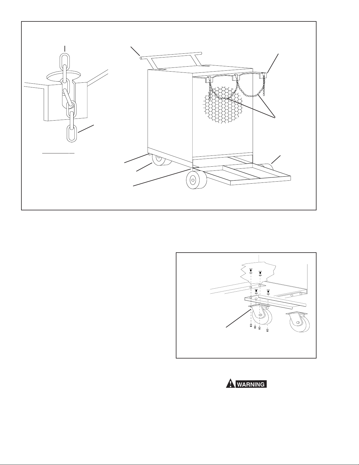
ENTRY POSITION HANDLE - 678402
UPPER CYLINDER RACK,
678350 (TR-11)
30510 (TR-12)
SECURED POSITION
TYPICAL CHAIN
MOUNTING DETAIL
FRONT BEAM - 678349
(2) SWIVEL CASTER - 950385
REAR PAN
678348 (TR-11)
30509 (TR-12)
Fig. 2 - Power Source on TR-12 Truck
5. Assemble Rear Pan/Rigid Casters.
On the TR-11, assemble the rear pan and the rigid
casters to the rear base of the unit in the same manner as the front beam and swivel casters.
On the TR-12, assemble the rear pan, to the power
source similar to that shown in Fig. 2.
6. To install the wheels, on the TR-12, you must remove
the wheel-sleeves. Then assemble the wheel between two flat washers and retain with cotter pin at
each end of the axle.
CHAIN - 678944
(1 SUPPLIED WITH (TR-11)
(2 SUPPLIED WITH (TR-12)
(2) RIGID CASTER 950386 (TR-11)
(2) REAR WHEEL 950384 (TR-12)
each side of the power source using the flatwasher
and 1" lg. 1/4"--20 screw (supplied) -- see Fig. 4.
7. Attaching gas cylinders and/or WC-8C water cooler.
When you put the cylinder(s) in place, pull the chain
tightly around it and place the excess chain into the
slotted-hole provided in the end of the rack. Be sure
to pull the link all the way down into the slot to secure
the chain (see Fig. 2). Do not just "loop" a link over
the end of the rack.
When you put an optional WC-8C, water cooler on a
TR-11, remove the center rear side panel screws from
the power source and attach the chain assembly to
NOTE: Rigid casters for Rear
Wheel Assy. on TR-11
Swivel Casters for Front
Wheel Assy. on All Units.
Fig. 3 - Typical Front End Assembly For All Trucks
Never lift a power source with cylinder(s) attached.
2
 Loading...