


PEG1
Caja de mandos
Centralina di controllo
UnidadedeControlo
Control unit
Кйвюфйп чейсйумпэ
Manual del operador
Manuale per l’operatore
Manual para o operador
Operating manual
ПдзгЯет Чейсйумпэ
443 392 --003 9606 Valid from Machine no 452 XXX--XXXX

SEGURIDAD 2................................................
DESCRIPCIÓN TÉCNICA 3....................................
INSTALACIÓN 9..............................................
OPERACIÓN (Estándar y Columna) 13...........................
OPERACIÓN (ARISTO 500) 14..................................
LOCALIZACIÓN DE AVERÍAS 15................................
INSTRUCCIONES DE CONEXIÓN PARA LAS PEG,
A6 VEC Y A2 19.........................................
SICUREZZA 21................................................
DESCRIZIONE TECNICA 22....................................
INSTALLAZIONE 28............................................
USO (Standard e Braccio) 32....................................
USO (ARISTO 500) 33..........................................
RICERCA GUASTI 34..........................................
INSTRUZIONI PER IL COLLEGAMENTO DI PEG1,
A6 VEC E A2 38.........................................
SEGURANÇA 40...............................................
DESCRIÇÃO TÉCNICA 41......................................
INSTALAÇÃO 47...............................................
OPERAÇÃO (Equipamento standard e de montante e braço) 51.....
OPERAÇÃO (ARISTO 500) 52...................................
DIAGNÓSTICO DE ANOMALIAS 53..............................
INSTRUÇÕES DE LIGAÇÃO PARA PEG1, A6 VEC E A2 57.........
SAFETY 59....................................................
TECHNICAL DESCRIPTION 60..................................
INSTALLATION 65.............................................
OPERATION (Standard and column and boom) 69.................
OPERATION (ARISTO 500) 70...................................
TROUBLESHOOTING 71.......................................
CONNECTION INSTRUCTIONS FOR PEG1, A6 VEC AND A2 74....
БУЦБЛЕЙБ 76.................................................
ФЕЧНЙКЗ РЕСЙГСБЦЗ 77.......................................
ЕГКБФБУФБУЗ 83.............................................
ЛЕЙФПХСГЙБ (УфЬнфбсф кбй Гесбньт) 87..........................
ЛЕЙФПХСГЙБ (ARISTO 500)88...................................
БНБЖЗФЗУЗ УЦБЛМБФЩН 89..................................
ПДЗГЙЕУ УХНДЕУЗУ PEG1 ÊÁÉ, A6 VEC КБИЩУ КБЙ A2 93........
ESQUEMA - SCHEMA - ESQUEMA - DIAGRAM - УЧЗМБ УХНДЕУЗУ 94...
Reservado el derecho de cambiar las especificaciones sin previo aviso.
Specifiche senza preavviso.
Reservamo--nos o direito de alterar as especificações sem aviso prévio.
Rights reserved to alter specifications without notice.
∆ιατηρεßται το δικαßωmα τροποποßησηj προδιαγραφþνΧωρßj προειδοποßηση.
WARNING
ARC WELDING AND CUTTING CAN BE INJURIOUS TO YOURSELF AND
OTHERS. TAKE PRECAUTIONS WHEN WELDING. ASK FOR YOUR
EMPLOYER’S SAFETY PRACTICES WHICH SHOULD BE BASED ON MANU-FACTURER’S HAZARD DATA.
ELECTRIC SHOCK -- Can kill
S Install and earth the welding unit in accordance with applicable standards.
S Do not touch live electrical parts or electrodes with bare skin, wet gloves or
wet clothing.
S Insulate yourself from earth and the workpiece.
S Ensure your working stance is safe.
FUMES AND GASES -- Can be dangerous to health
S Keep your head out of the fumes.
S Use ventilation, extraction at the arc, or both, to keep fumes and gases from
your breathing zone and the general area.
ARC RAYS -- Can injure eyes and burn skin
S Protect your eyes and body. Use the correct welding screen and filter lens
and wear protective clothing.
S Protect bystanders with suitable screens or curtains.
FIRE HAZARD
S Sparks (spatter) can cause fire. Make sure therefore that there are no
inflammable materials nearby.
NOISE -- Excessive noise can damage hearing
S Protect your ears. Use ear defenders or other hearing p rotection.
S Warn bystanders of the risk.
MALFUNCTION
S Call for expert assistance in the event of malfunction.
READ AND UNDERSTAND THE OPERATING MANUAL
BEFORE INSTALLING OR OPERATING.
PROTECT YOURSELF AND OTHERS!
mmvarnea
-- 5 8 --

SAFETY
SAFETY
Users of ESAB automatic welding machines have ultimate responsibility for ensuring
that anyone who works on or near the equipment observes all the relevant safety
precautions.
The following recommendations should be observed in addition to the standard regulations that apply to the work place.
All work must be carried out according to the specified instructions by personnel who
are thoroughly familiar with the operation of the welding machine.
Incorrect or unintentional operation of the equipment may lead to a hazardous situation which can result in injury to the operator and damage to the equipment.
1. Anyone who uses the automatic welding machine must be familiar with:
S its operation
S the location of emergency stops
S its function
S relevant safety precautions
To make this easier each switch, pushbutton or potentiometer is marked with a
symbol or text that indicates its function when activated.
2. The operator must ensure that:
S no unauthorized person is stationed within the working area of the machine
when it is started up.
S that no--one is in a hazardous position when the carriage or slide mechan-
isms are operated.
3. The work place must:
S be clear of mechanical components, tools, or other obstructions that could
prevent the operator from moving freely within the working area.
S be organized so that there is free access to the emergency stop.
4. Personal safety equipment
S Always wear recommended personal safety equipment, such as safety
glasses, flame--proof clothing, safety gloves.
S Do not wear loose--fitting items, such as scarves, b racelets, etc., which could
become trapped.
5. General precautions
Live electrical components are normally shielded from accidental contact.
S Make sure the return cable is connected securely.
S Work on high voltage components may only be carried out by a qualified
electrician.
S Appropriate fire extinguishing equipment must be clearly marked and close
at hand.
S Lubrication and maintenance must not be carried out on the equipment dur-
ing its operation.
-- 5 9 --df00f1ea

TECHNICAL DESCRIPTION
TECHNICAL DESCRIPTION
The PEG1 control unit is used together with standard automatic welding machines
A2, A6 and column and boom units for adjusting and controlling welding parameters.
It is used for automated and mechanised submerged arc and MIG/MAG welding with
AC or DC.
The table below shows the order numbers for the various base models available and
which automatic welding machines they can be used with.
Order number Control unit PEG1
333 001--884 Control unit for A2S Mini Master (A2 SFD, A2 SGD)
333 001--885 Control unit for A2S Mini Master and CaB control system
333 001--891 Control unit for A2 Multitrac (A2 TFD, A2 TGD)
333 001--892 Control unit for A2S Mini Master and CaB control system
333 001--893 Control unit for A2 BFD/BGD
333 001--894 Control unit for A2 Mini Master --ARISTO
333 001--895 Control unit for A2 MULTITRAC --ARISTO
333 001--896 Control unit for A2 MKR RCC
333 001--901 Control unit for A6S Arc Master (A6 SFD) and A6S G Master (A6 SGD)
333 001--903 Control unit for A6S Arc Master with CaB control system
333 001--905 Control unit for A6S Arc Master --AC and A6S Tandem Master
333 001--906 Control unit for A6S Arc Master RCC
333 001--910 Control unit for A6 Mastertrac (A6 TFD, A6 TGD)
333 001--912 Control unit for A6B Master (A6 BFD, A6 BGD)
333 001--913 Control unit for A6S Arc Master with CaB control system
333 001--914 Control unit for A6 MKR AC RCC
333 001--915 Control unit for A6 MKR RCC
Technical data:
Control unit PEG1
Supply voltage from ESAB: automatic welding power sources, semi--automatic
welding power sources or external
Supply output 530 VA
Output voltage rotor circuit (adjustable) 0--42 V DC
Output voltage winding circuit (can be reconfigured) 36/60 V DC
Output power (per rotor circuit) RMS 160 VA
Output power (per rotor circuit) mean value 155 W
Switching function for current switch 7,5 A
Switching function for (external use) gas valve 7,5 A
Switching function for (electrically isolated) remote control 2A
Enclosure class
(Equipment that is marked IP 23 is designed for indoor and outdoor use).
42V, 50--60 Hz
IP 23
Max ambient temp. 45_C
Weight 5,5 kg
Width 175 mm
Depth 255 mm
Height 210 mm
dga7d1ea
-- 6 0 --
TECHNICAL DESCRIPTION
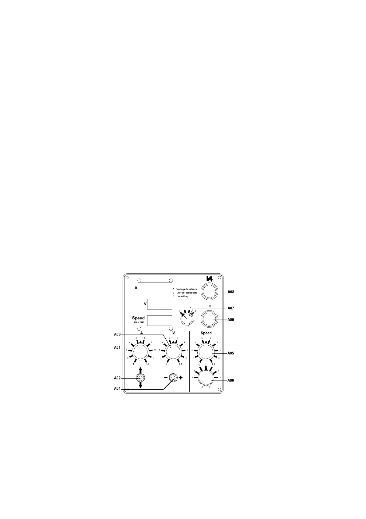
The PEG1 control unit has the following controls on the front panel:
A01 Potentiometer
for selecting welding current.
A02 Switch
for manual choice of electrode
A03 Potentiometer
for selecting welding voltage.
A04 Switch
for increasing (+) or decreasing (--) welding voltage using the motor-driven
potentiometer in the welding power source.
Presetting of the welding voltage using switch A 07 is not possible in the
way described on page 62 in point 3 (”Presetting”).
A05 Potentiometer
for selecting travel speed.
A06 Switch
for selecting automatic start, touch start or manual start, and travel direction.
S Position 1 (automatic start) -- travel starts once arc has been struck.
S Position 2 (touch start) -- travel starts at the same time as wire feed.
S Position 3 (manual start) -- travel starts immediately without wire feed.
dga7d03a
-- 6 1 --dga7d1ea

TECHNICAL DESCRIPTION
A07 Switch
for presetting, see wiring instructions on page 74.
1. Position 1 -- ”Voltage feedback”
Normally used for MIG/MAG, submerged arc welding and aluminium
welding with thin wires.
At welding voltages below 26 V the wire feed motor runs at a
constant speed, which is selected using potentiometer A 03.
Suitable for aluminium welding.
At welding voltages above 26 V the wire feed speed -- and hence
welding current -- follows variations in the welding voltage, i.e. if the
welding voltage increases so does the welding current, and vice versa.
2. Position 2 -- ”Current feedback”
Normally used for MIG/MAG, submerged arc welding and for welding
thicker aluminium.
Wire feed speed is controlled b y the welding current.
The preset current is adjusted using potentiometer A 01 (see position
3 on page 62) and is independent of the wire diameter used.
3. Position 3 -- ”Presetting”
The welding current, voltage and travel speed are preset using the respective potentiometers.
S The travel speed can always be preset. Travel speed is adjusted
using the ”Speed” potentiometer A 05.
S The welding voltage can only be p reset when using a welding
power source equipped with a preselector device
(order no. 365 580--880). The welding voltage is selected using potentiometer V (A 03).
S The welding current can only be preset when welding with the
switch in position 2.
d. Set A 07 to position 3.
e. Select the welding current using potentiometer A (A 01).
f. Set A 07 to position 2 once all preselections have been made.
A08 Pushbutton (with yellow lamp)
used to start welding. The lamp indicates that welding current is available.
The button must be held down until the arc has been struck, i.e. until welding current is flowing.
A09 Pushbutton (red)
used to stop welding
-- Numerical display ”A”
displays average welding current in Amps, accuracy 1.5%, 3 figure display
(1000 indication + 3 figures, giving maximum 1999 A)
-- Numerical display ”V”
displays true RMS welding voltage in Volts, accuracy 1.5%, 3 figures
-- Numerical display ”Speed cm/min”
shows average travel speed in cm/min, 3 figures
dga7d1ea
-- 6 2 --

On the rear panel of the control unit are:
A16 Socket (8 pin) ”Control Cable”
for connecting the control cable of the
welding power source 42 V.
A17 Socket (2 pin) ”Gas/Flux Valve”
for connecting the gas valve or flux valve.
A18 Socket (2 pin) ”Pilot Lamp”
for connecting a pilot lamp (6 V max 1 A).
A19 Socket (5 pin) ”Electrode Motor”
for connecting wire feed motor.
S A + to motor rotor
S B 0 to motor rotor
S C + to motor winding
S D 0 to motor winding
TECHNICAL DESCRIPTION
aga7d002
S E spare
A20 Socket (5 pin) ”Travel Motor”
for connecting travel motor.
S A + to motor rotor
S B 0 to motor rotor
S C + to motor winding
S D 0 to motor winding
S E spare
A21 Cable
for connecting meter shunt
800 A /60 mV or 1500 A/6 mV.
A23 Fuse (10 A rapid)
for supply voltage 42 V.
A24 Potentiometer ”Burn--back Time”
for adjusting burn--back time,
range 0.1 -- 1.2 sec.
-- Three plugged holes
to allow routing of cables (1, 2 and 3).
A25 Socket
for connecting emergency stop and
remote control functions (column and boom).
d412094s
-- 6 3 --dga7d1ea

TECHNICAL DESCRIPTION
The control unit consists of the following units:
A Connection block
for connecting external supply voltage
-- Display card (circuit card)
located inside front panel
D, E Regulator card (2 identical circuit cards)
for wire feed motor (D) and travel motor (E).
S the regulator can be configured for a variety of different motors
(see point 3 on page 66.)
S the regulator also provides 2 current overload protection functions.
The first is triggered immediately the motor current exceeds 20 A.
The second has a time delay and on delivery is set for 1.5 x the
motor current rating.
F Meter card (circuit card)
G Sequence card (circuit card)
H Power supply, consisting of:
A1 Circuit card
A5 Transformer 42 V
-- Fuses
for supply voltage.
S1,S2 +/-- 15 V and -- 5 V (1A slow).
S3 + 5 V and pilot lamp (3.15 A slow).
A2 for primary supply to transformer (1 A slow).
A3 Single phase rectifier bridge
A4 Voltage regulator
A6 Connection block for supply voltage 42 V
NOTE! The supply voltage is marked on the control unit.
I Space for additional card
prepared connections as shown in wiring diagram.
dga7d1ea
aga7d007
-- 6 4 --

INSTALLATION
INSTALLATION
IMPORTANT!
Read all relevant manuals and safety precautions carefully before starting to
unpack and install the equipment!
NOTE! Make sure installation is carried out by suitably trained personnel.
Check that the control unit is properly connected and set up for the intended
purpose.
If you are certain that this has been done then points 1 to 5 below can be omitted.
1. Dismantling of control unit PEG1, see fig on page 65.
S Undo the four screws that hold the front panel (1) in place.
S Disconnect the display card (2) from the meter card (3) by unplugging the 96 pin
plug (4).
S Release the front panel (1) from the sequence card (5) by unplugging the ribbon
cable (6) and plug (7) on the supply unit (8).
S Remove the rear panel by removing all the circuit cards, followed by the four
screws that hold the panel in place.
S When refitting the front panel make sure the flexible section of the display card is
not trapped. Position the left side of the front panel first and then slide it into
place.
2. Supply voltage 42 V.
aga7d008
-- 6 5 --dga7i1ea

INSTALLATION
3. Choice of motors
Check that regulator cards D and E for the wire feed motor and travel motor
respectively are configured for the correct motor, as shown in the table and diagram on page 66.
Regulator card order no. 341 859--880 , --884, --886.
S Cable x to pin 1 for A6 VEC 8000 r/min, 4000 r/min.
S Cable x to pin 1 for Parvalux travel motor (MKR column and boom).
S Cable x to pin 2 for A6 VEC 2000 r/min.
S Cable x to pin 2 for A6 Mastertrac for travel.
S Cable x to pin 3 for A6 VEC 1000 r/min.
S Cable x to pin 4 for A2 Elektrolux for wire feed (sub--arc welding)
S Cable x to pin 4 for A6 VEC, 4,000 r.p.m. for travel motion.
S Cable x to pin 5 for A2 Elektrolux for travel.
S Cable x to pin 5 for Dunker motor for Multitrac.
S Cable x to pin 1 for A2 Elektrolux for wire feed (MIG/MAG welding)
S Cable B to pin 7 for A6 VEC 4000, 2000, 1000 r/min for wire feed.
S Cable B to pin 7 for Parvalux travel motor (MKR column and boom).
S Cable B to pin 8 for all A2 motors.
S Cable B to pin 8 for Dunker motor for Multitrac.
S Cable B to pin 8 for A6 VEC for travel.
S Cable B to pin 8 for Mastertrac for travel.
S Cable B to pin 8 for A6 VEC 8000 r/min for wire feed.
S Cable B to pin 8 for A6 VBE (DK) for travel.
S Cable B to pin 8 for spare.
aga7d001
Refer also to the table for connection instructions on page 74.
Note: Figures given, e.g: A6 VEC 8000 r/min refer to the actual speed at 42 V
(not rotor version).
dga7i1ea
-- 6 6 --

INSTALLATION
When cable x is connected to the motor, RI compensation and current limiting functions are automatically adapted to the rating of the selected motor.
4. Configuring the sequence card
S On the end of the sequence card (end nearest control panel) there is a 3 pin
edge connector which is configured usinga2pinsocketconnector.
Bottom pin connected to middle pin
-- Submerged arc and MIG/MAG welding with tube wire.
Top pin connected to middle pin
-- General MIG/MAG welding and submerged arc welding with TWIN arc.
-- 6 7 --dga7i1ea

INSTALLATION
5. External equipment (I/O option)
At the rear of the control unit are three plugged holes marked 1, 2 och 3 desig-
ned for the passage of cables (se diagram on page 63). When any of these
inputs are used the plug must be replaced with a grommet, Pr 15,2, to seal the
incoming cables.
It is possible to control the welding cycle remotely by connecting external equipment to the connection block in the control unit.
See the diagram on page 95.
For column and boom versions see the diagram on page 99.
S External emergency stop, see fig 11 on page 68.
S Stop switch for travel movement (left or right), see fig 12 on page 68.
S External start switch for welding.
S External stop switch for welding.
S Remote control of manual travel movement, see fig 13 on page 68.
S Electrically isolated current relay function, see fig 14 on page 68.
Electrically isolated when welding current is flowing.
S Monitoring of welding voltage using meter cable connected from work piece
to connection block B 9. Welding voltage is normally monitored using shunt
input and socket A 16, pin G.
dga7i1ea
aga7d005
-- 6 8 --

OPERATION (Standard and column and boom)
OPERATION (Standard and column and boom)
1. Position the automatic welding head at the start of the weld joint.
2. Position the wire near the work piece using switch A 02.
3. Cut the wire at an angle.
4. Set switch A 07 to position 3 ”Presetting”.
5. Adjust the welding current using potentiometer A 01.
6. Adjust the travel speed using potentiometer A 05.
7. For welding power sources equipped with a preselector device:
S Adjust the welding current using potentiometer A 03.
For welding power sources not equipped with preselector device:
S Adjust the welding voltage using switch A 04.
8. Set switch A 07 to position 1 ”Voltage feedback” or position 2 ”Current feedback”.
9. Select the start mode and travel direction using switch A 06.
(position 1 automatic start, position 2 touch start, position 3 manual start).
10. Start welding by pressing pushbutton A 08 until welding current flows and indica-
tor lamp A 08 lights up.
11. Press pushbutton A 09 to stop welding.
12. If necessary adjust burn--back time u sing potentiometer A 22.
13. If switch A 07 is set to position 1 ”Voltage feedback” during welding, it will not be
possible to preset the welding current as described in point 5 (on page 69).
S Adjust the welding current using potentiometer A 01 after welding has
started.
dga7d03a
-- 6 9 --dga7o1ea

OPERATION (ARISTO 500)
OPERATION (ARISTO 500)
1. Position the welding head at the start by setting switch A06 to position 3.
2. Position the wire near the work piece using switch A 02.
3. Set switch A 07 to position 3 ”Presetting.
4. Adjust the travel speed using potentiometer A 05.
5. Choose a suitable welding program using the Aristo 500 control unit, e.g. MIG/
MAG, Pulse, Almg, Ar and 1,2 mm.
6. Adjust the wire feed speed using the Aristo 500 control unit.
7. Set switch A07 to the welding position.
8. Select the start mode and travel direction using switch A 06
(position 1 automatic start, position 2 touch start, position 3 manual start).
9. Start welding by pressing pushbutton A 08 until welding current flows and indica-
tor lamp A 08 lights up.
10. If necessary adjust the voltage using the increase/decrease buttons on the
Aristo control unit.
The current can also be adjusted using the wire feed speed increase/decrease
buttons.
11. Press pushbutton A 09 to stop welding.
12. If necessary adjust burn--back time u sing potentiometer A 22.
dg412094
dga7o1ea
-- 7 0 --

TROUBLESHOOTING
Equipment
S See diagram 333 232 on page 95.
For column and boom versions see diagram 443 386 on page 99.
S Universal meter
S 2 types of extension cards for Euro card format:
1. Model DIN 41612 type C equipped for a--c
2. Model DIN 41612 type D equipped for a--c
Check
S that the control unit is correctly connected as shown in diagram
333 232,
see diagram 443 386 for column and boom versions
S that cables and connections, including those for external equipment,
are undamaged and correctly connected.
S that the controls are correctly set.
S that all supply voltages are correct.
TROUBLESHOOTING
Note
S that the 3 row connectors on the meter card are connected to the dis-
play card.
S that cables or circuit cards must not be disconnected while power is on.
Wait 20 seconds after switching off before doing anything.
S that the circuit card contact rows are marked as follows:
a = nearest circuit card
b = middle row
c = Furthest from circuit card
1 = the top 3(2) connections
32 = the bottom 3(2) connections
S that the system zero is connected to the shunt/electrode and does not
carry earth voltage.
POSSIBLE FAULTS
It is possible to reverse the connections!
1. Symptom Fuse A 23 on back panel blows when power is switched on.
Cause 1.1 Shorting in either motor regulator
Action Measure resistance between a18 -- a30 on both motor regulators.
If it is less than 10 ohm, replace the regulator.
Cause 1.2 Shorting in a drive or brake transistor.
Action Measure the resistance between the transistor casing and each leg individ-
ually. The resistance should be higher than 10 ohm.
-- 7 1 --dga7f1ea

TROUBLESHOOTING
2. Symptom Fluctuating or faulty meter readings.
Cause 2.1
Defective meter card.
Action Replace meter card.
Cause 2.2 + 5 V supply voltage from supply unit is faulty.
Action Replace supply unit.
Cause 2.3 Sequence card defective
Action
Replace sequence card.
3. Symptom Wire feed motor or travel motor do not start.
Cause 3.1 Motor defective or wrongly connected.
Action Disconnect the motor plug from the control unit and check the resistance
between pins A and B. It should be less than 50 ohm.
Cause 3.2 Motor regulator defective.
Action Replace the motor regulator.
Cause 3.3 Sequence card defective.
Action Replace the sequence card.
Cause 3.4 Motor field windings defective or wrongly connected (only applies to motors
with field windings).
Action Check the resistance between pins C and D in the motor plug. It should be
between 100 -- 1000 ohm.
Cause 3.5 No field voltage (only applies to motors with field windings).
Action Measure the voltage between pins C and D. If zero, replace S 4 on the
supply unit.
4. Symptom Gas valve not working
Cause 4.1 Gas valve defective. It should have the same control voltage as the weld-
ing power source.
Action Check the gas valve and its connections.
Cause 4.2 Sequence card defective.
Action Replace sequence card
5. Symptom Pilot lamp does not light.
Cause 5.1 Lamp defective.
Action Check the lamp and its connections.
Cause 5.2 Supply unit defective.
Action Measure the voltage between pins A and B of socket A 18. It should be 6 V
AC. If there is no voltage check the supply unit and replace if defective.
Check fuse S 3 in the supply unit.
6. Symptom Welding power source main contactor not activated when A 08 is pressed.
Cause 6.1 Sequence card defective.
Action
Press A 08. If the wire feed starts but the power source does not supply
any voltage, replace the sequence card.
dga7f1ea
-- 7 2 --
Cause 6.2 Front panel or connections are defective.
Action
Check the circuit (as shown in fig
13 on page 68) on the rear panel, se-
quence card and front panel.
7. Symptom Presetting does not work satisfactorily.
Cause 7.1 Meter card defective.
Action Replace meter card.
Cause 7.2 Sequence card defective.
Action Replace sequence card.
8. Symptom Display too dark or too bright.
TROUBLESHOOTING
Cause 8.1
Action
Fuse S 3 in supply unit defective.
Replace fuse.
Cause 8.2 Faulty + 5 V supply.
Action Replace supply unit.
9. Symptom Difficulty starting.
Cause 9.1 Slag on tip of wire.
Action Cut wire at an angle.
10. Symptom
Incorrect welding voltage (too high or too low).
Cause 10.1 Meter card defective.
Action Replace meter card.
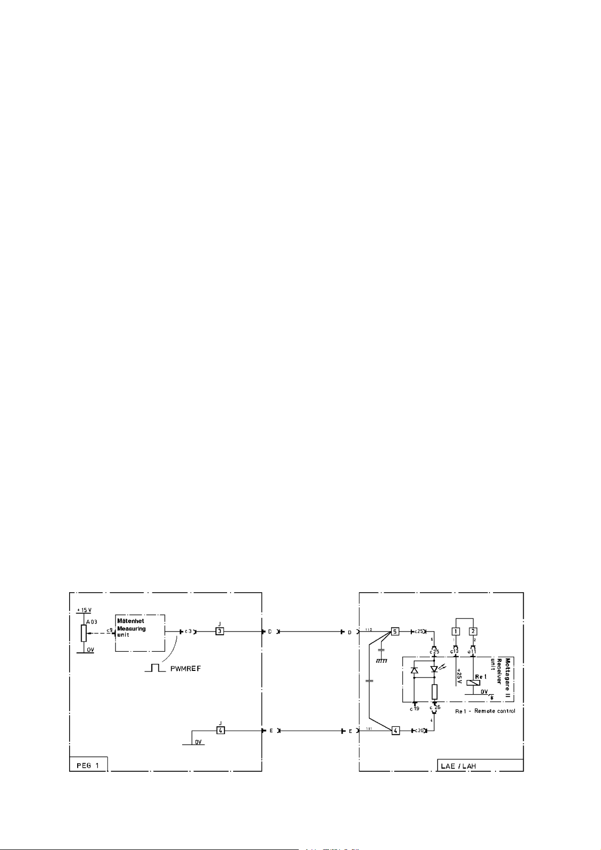
Cause 10.2 Faulty communication between meter card and receiver.
Action Check circuit as shown in figure on page 73.
Cause 10.3 Receiver card defective.
Action Replace receiver card.
aga7d004
-- 7 3 --dga7f1ea

8,0 -- 12,7mm
Carbon electrode
Arc air gouging
X--1
Position 2
Connect bottom
pintomiddlepin
B--7
Strip
0,5x30--100mm
Submerged arc
Aluminium
Gas metal arc
1,2 -- 1,6mm
Steel -- stainless
Gas metal arc
1,2 -- 4mm
Hollow wire
Gas metal arc
welding
welding
welding
welding
Position 1
Position1or2 Position1or2 Position 1
Connect bottom
pin to middle
pin
Connect top pin
to middle pin
Connect top pin to
middle pin
Connect bottom
pintomiddlepin
X--1
X--1
X--1
X--1
X--1
X--1
B--7
B--8
B--8
B--7
B--8
B--7
74:1 74:1 74:1 74:1 74:1 156:1 156:1
X--6
X--6
X--6
X--6
B--8
B--8
B--8
B--8
CONNECTION INSTRUCTIONS FOR PEG1, A6 VEC AND A2
Twin wire
Single wire
Electrode
2x1,2 -- 3,0mm
Submerged arc
2,5 -- 6mm
Submerged arc
welding
welding
Welding method
Direct Direct Direct Direct Direct Direct
Alter-
Current type Direct
nating
Switch
Position 1
Position1or2
(feed--back)
Connect bottom
pintomiddlepin
Connect bottom
pintomiddlepin
2--pin edge socket
74
X--1
B--7
156:1
(74:1)
X--1
B--7
Regulator card
connection
(A6 VEC)
Ratio (A6 VEC) 156:1
Motor rotor r.p.m.
4000 4000 4000 8000 4000 8000 8000 4000 4000
(A6 VEC)
X--4
B--8
X--4
B--8
Regulator card
connection
(A2)
 Loading...