


INSTRUCTION MANUAL
PCM-500i
PLASMA ARC CUTTING PACKAGES
F-15-296-E
Feb., 2004
This manual provides complete instructions for the following PCM-500i cutting packages starting with Serial No. PORI612001:
ESAB P/N 36314 - 208/230 V, 1-Phase, 50/60 Hz
ESAB P/N 36316 - 400 V (380/415 V), 3-Phase, 50/60 Hz
These INSTRUCTIONS are for experienced operators. If you are not fully familiar with the principles of operation and
safe practices for arc welding equipment, we urge you to read our booklet, "Precautions and Safe Practices for Arc
Welding, Cutting, and Gouging," Form 52-529. Do NOT permit untrained persons to install, operate, or maintain this
equipment. Do NOT attempt to install or operate this equipment until you have read and fully understand these
instructions. If you do not fully understand these instructions, contact your supplier for further information. Be sure
to read the Safety Precautions before installing or operating this equipment.
Be sure this information reaches the operator.
You can get extra copies through your supplier.

USER RESPONSIBILITY
This equipment will perform in conformity with the description thereof contained in this manual and accompanying
labels and/or inserts when installed, operated, maintained and repaired in accordance with the instructions provided. This equipment must be checked periodically. Malfunctioning or poorly maintained equipment should not
be used. Parts that are broken, missing, worn, distorted or contaminated should be replaced immediately. Should
such repair or replacement become necessary, the manufacturer recommends that a telephone or written request
for service advice be made to the Authorized Distributor from whom purchased.
This equipment or any of its parts should not be altered without the prior written approval of the manufacturer. The
user of this equipment shall have the sole responsibility for any malfunction which results from improper use, faulty
maintenance, damage, improper repair or alteration by anyone other than the manufacturer or a service facility
designated by the manufacturer.
TABLE OF CONTENTS
SECTION TITLE PAGE
PARAGRAPH
SECTION 1 DESCRIPTION ................................................................................................. 7
1.1 General ............................................................................................................. 7
1.2 Scope ................................................................................................................ 7
1.3 Packages Available ........................................................................................... 7
1.4 Specifications .................................................................................................... 8, 9
1.5 Optional Accessories ........................................................................................ 9
SECTION 2 INSTALLATION ................................................................................................ 10
2.1 General ............................................................................................................. 10
2.2 Equipment Required ......................................................................................... 10
2.3 Location ............................................................................................................ 10
2.4 Inspection.......................................................................................................... 10
2.5 Primary Electrical Input Connections................................................................. 10
2.6 Secondary (Output) Connections ...................................................................... 11
2.7 Connecting PCM-500i for 200(208) Vac Input ................................................... 13
SECTION 3 OPERATION ..................................................................................................... 15
3.1 Operation .......................................................................................................... 15
3.2 PCM-500i Controls ............................................................................................ 15
3.3 Assembling PT-31XL Consumable Parts .......................................................... 16
3.4 Cutting with the PT-31XL .................................................................................. 16
3.5 Operating Techniques ....................................................................................... 17
3.6 Common Cutting Problems ............................................................................... 18
SECTION 4 MAINTENANCE ................................................................................................ 19
4.1 General ............................................................................................................. 19
4.2 Inspection and Cleaning .................................................................................... 19
4.3 Flow Switch ....................................................................................................... 19
SECTION 5 TROUBLESHOOTING ..................................................................................... 20
5.1 Troubleshooting ................................................................................................ 20
5.2 Troubleshooting Guide ...................................................................................... 20
5.3 Sequence of Operation ..................................................................................... 25
SECTION 6 REPLACEMENT PARTS.................................................................................. 33
6.1 General ............................................................................................................. 33
6.2 Ordering ............................................................................................................ 33
2

SAFETY PRECAUTIONS
WARNING: These Safety Precautions are for
your protection. They summarize precautionary information from the references listed in
Additional Safety Information section. Before
performing any installation or operating procedures, be
sure to read and follow the safety precautions listed below
as well as all other manuals, material safety data sheets,
labels, etc. Failure to observe Safety Precautions can result
in injury or death.
PROTECT YOURSELF AND OTHERS
Some welding, cutting, and gouging
processes are noisy and require ear
protection. The arc, like the sun, emits
ultraviolet (UV) and other radiation and
can injure skin and eyes. Hot metal can cause burns.
Training in the proper use of the processes and equipment is essential to prevent accidents. Therefore:
1. Always wear safety glasses with side shields in any work
area, even if welding helmets, face shields, and goggles
are also required.
2. Use a face shield fitted with the correct filter and cover
plates to protect your eyes, face, neck, and ears from
sparks and rays of the arc when operating or observing
operations. Warn bystanders not to watch the arc and
not to expose themselves to the rays of the electric-arc
or hot metal.
3. Wear flameproof gauntlet type gloves, heavy long-sleeve
shirt, cuffless trousers, high-topped shoes, and a welding helmet or cap for hair protection, to protect against
arc rays and hot sparks or hot metal. A flameproof apron
may also be desirable as protection against radiated
heat and sparks.
4. Hot sparks or metal can lodge in rolled up sleeves,
trouser cuffs, or pockets. Sleeves and collars should be
kept buttoned, and open pockets eliminated from the
front of clothing
5. Protect other personnel from arc rays and hot sparks
with a suitable non-flammable partition or curtains.
6. Use goggles over safety glasses when chipping slag or
grinding. Chipped slag may be hot and can fly far.
Bystanders should also wear goggles over safety glasses.
FIRES AND EXPLOSIONS -- Heat from
flames and arcs can start fires. Hot slag
or sparks can also cause fires and explosions. Therefore:
1. Remove all combustible materials well away from the
work area or cover the materials with a protective nonflammable covering. Combustible materials include wood,
cloth, sawdust, liquid and gas fuels, solvents, paints and
coatings, paper, etc.
2. Hot sparks or hot metal can fall through cracks or
crevices in floors or wall openings and cause a hidden
smoldering fire or fires on the floor below. Make certain
that such openings are protected from hot sparks and
metal.“
3. Do not weld, cut or perform other hot work until the
workpiece has been completely cleaned so that there
are no substances on the workpiece which might produce flammable or toxic vapors. Do not do hot work on
closed containers. They may explode.
4. Have fire extinguishing equipment handy for instant use,
such as a garden hose, water pail, sand bucket, or
portable fire extinguisher. Be sure you are trained in its
use.
5. Do not use equipment beyond its ratings. For example,
overloaded welding cable can overheat and create a fire
hazard.
6. After completing operations, inspect the work area to
make certain there are no hot sparks or hot metal which
could cause a later fire. Use fire watchers when necessary.
7. For additional information, refer to NFPA Standard 51B,
"Fire Prevention in Use of Cutting and Welding Pro-
--
cesses", available from the National Fire Protection Association, Batterymarch Park, Quincy, MA 02269.
ELECTRICAL SHOCK -- Contact with live
electrical parts and ground can cause
severe injury or death. DO NOT use AC
welding current in damp areas, if movement is confined, or if there is danger of
falling.
1. Be sure the power source frame (chassis) is connected
to the ground system of the input power.
2. Connect the workpiece to a good electrical ground.
3. Connect the work cable to the workpiece. A poor or
missing connection can expose you or others to a fatal
shock.
4. Use well-maintained equipment. Replace worn or damaged cables.
5. Keep everything dry, including clothing, work area, cables,
torch/electrode holder, and power source.
6. Make sure that all parts of your body are insulated from
work
and from ground.
7. Do not stand directly on metal or the earth while working
in tight quarters or a damp area; stand on dry boards or
an insulating platform and wear rubber-soled shoes.
8. Put on dry, hole-free gloves before turning on the power.
9. Turn off the power before removing your gloves.
10. Refer to ANSI/ASC Standard Z49.1 (listed on next page)
for specific grounding recommendations. Do not mistake
the work lead for a ground cable.
ELECTRIC AND MAGNETIC FIELDS —
May be dangerous. Electric current flowing through any conductor causes localized Electric and Magnetic Fields
(EMF). Welding and cutting current creates EMF around welding cables and
welding machines. Therefore:
1. Welders having pacemakers should consult their physician before welding. EMF may interfere with some pacemakers.
2. Exposure to EMF may have other health effects which are
unknown.
3. Welders should use the following procedures to minimize
exposure to EMF:
A. Route the electrode and work cables together. Secure
them with tape when possible.
B. Never coil the torch or work cable around your body.
C. Do not place your body between the torch and work
cables. Route cables on the same side of your body.
D. Connect the work cable to the workpiece as close as
possible to the area being welded.
E. Keep welding power source and cables as far away
from your body as possible.
10/98
3
FUMES AND GASES -- Fumes and
gases, can cause discomfort or harm,
particularly in confined spaces. Do
not breathe fumes and gases. Shielding gases can cause asphyxiation.
Therefore:
1. Always provide adequate ventilation in the work area by
natural or mechanical means. Do not weld, cut, or gouge
on materials such as galvanized steel, stainless steel,
copper, zinc, lead, beryllium, or cadmium unless positive
mechanical ventilation is provided. Do not breathe fumes
from these materials.
2. Do not operate near degreasing and spraying operations. The heat or arc rays can react with chlorinated
hydrocarbon vapors to form phosgene, a highly toxic
gas, and other irritant gases.
3. If you develop momentary eye, nose, or throat irritation
while operating, this is an indication that ventilation is not
adequate. Stop work and take necessary steps to improve ventilation in the work area. Do not continue to
operate if physical discomfort persists.
4. Refer to ANSI/ASC Standard Z49.1 (see listing below)
for specific ventilation recommendations.
5. WARNING: This product, when used for welding or
cutting, produces fumes or gases which
contain chemicals known to the State of
California to cause birth defects and, in
some cases, cancer. (California Health &
Safety Code
CYLINDER HANDLING -- Cylinders, if
mishandled, can rupture and violently
release gas. Sudden rupture of cylinder, valve, or relief device can injure or
kill. Therefore:
1. Use the proper gas for the process and use the proper
pressure reducing regulator designed to operate from
the compressed gas cylinder. Do not use adaptors.
Maintain hoses and fittings in good condition. Follow
manufacturer's operating instructions for mounting regulator to a compressed gas cylinder.
2. Always secure cylinders in an upright position by chain
or strap to suitable hand trucks, undercarriages, benches,
walls, post, or racks. Never secure cylinders to work
tables or fixtures where they may become part of an
electrical circuit.
3. When not in use, keep cylinder valves closed. Have
valve protection cap in place if regulator is not connected. Secure and move cylinders by using suitable
hand trucks. Avoid rough handling of cylinders.
4. Locate cylinders away from heat, sparks, and flames.
Never strike an arc on a cylinder.
5. For additional information, refer to CGA Standard P-1,
"Precautions for Safe Handling of Compressed Gases in
Cylinders", which is available from Compressed Gas
Association, 1235 Jefferson Davis Highway, Arlington,
VA 22202.
§25249.5 et seq.)
EQUIPMENT MAINTENANCE -- Faulty or
improperly maintained equipment can
cause injury or death. Therefore:
1. Always have qualified personnel perform the installation, troubleshooting, and maintenance work. Do not
perform any electrical work unless you are qualified to
perform such work.
2. Before performing any maintenance work inside a power
source, disconnect the power source from the incoming
electrical power.
3. Maintain cables, grounding wire, connections, power
cord, and power supply in safe working order. Do not
operate any equipment in faulty condition.
4. Do not abuse any equipment or accessories. Keep
equipment away from heat sources such as furnaces,
wet conditions such as water puddles, oil or grease,
corrosive atmospheres and inclement weather.
5. Keep all safety devices and cabinet covers in position
and in good repair.
6. Use equipment only for its intended purpose. Do not
modify it in any manner.
ADDITIONAL SAFETY INFORMATION -- For
more information on safe practices for electric arc welding and cutting equipment, ask
your supplier for a copy of "Precautions and
Safe Practices for Arc Welding, Cutting and
Gouging", Form 52-529.
The following publications, which are available from the
American Welding Society, 550 N.W. LeJuene Road, Miami, FL 33126, are recommended to you:
1. ANSI/ASC Z49.1 - "Safety in Welding and Cutting"
2. AWS C5.1 - "Recommended Practices for Plasma Arc
Welding"
3. AWS C5.2 - "Recommended Practices for Plasma Arc
Cutting"
4. AWS C5.3 - "Recommended Practices for Air Carbon
Arc Gouging and Cutting"
5. AWS C5.5 - "Recommended Practices for Gas Tungsten
Arc Welding“
6. AWS C5.6 - "Recommended Practices for Gas Metal Arc
Welding"“
7. AWS SP - "Safe Practices" - Reprint, Welding Handbook.
8. ANSI/AWS F4.1, "Recommended Safe Practices for
Welding and Cutting of Containers That Have Held
Hazardous Substances."
MEANING OF SYMBOLS - As used throughout this manual: Means Attention! Be Alert!
Your safety is involved.
Means immediate hazards which, if
not avoided, will result in immediate,
serious personal injury or loss of life.
Means potential hazards which could
result in personal injury or loss of life.
Means hazards which could result in
minor personal injury.
4
SP98-10

PRÉCAUTIONS DE SÉCURITÉ
AVERTISSEMENT: Ces règles de sécurité ont pour objet
d’ assurer votre protection. Veillez à lire et à observer les
précautions énoncées ci-dessous avant de monter l’
équipement ou de commercer à l’utiliser. Tout défaut
d’observation de ces précautions risque d’entraîner des
blessures graves ou mortelles.
1. PROTECTION INDIVIDUELLE-- Les brûlures de la
peau et des yeux dues au rayonnement de l’arc
électrique ou du métal incandescent, lors du soudage
au plasma ou à l’électrode ou lors du gougeage à
l’arc, peuvent s’avérer plus graves que celles
résultant d’une exposition prolongée au soleil. Aussi
convient-il d’observer les précautions suivantes:
a. Portez un écran facial adéquat muni des plaques
protectrices et des verres filtrants appropriés afin de
vous protéger les yeux, le visage, le cou et les oreilles
des étincelles et du rayonnement de l’arc électrique
lorsque vous effectuez des soudures ou des coupes
ou lorsque vous en observez l’exécution.
AVERTISSEZ les personnes se trouvant à proximité
de façon à ce qu’elles ne regardent pas l’arc et à ce
qu’elles ne s’exposent pas à son rayonnement, ni à
celui du métal incandescent.
b. Portez des gants ignifugés à crispins, une tunique
épaisse à manches longues, des pantalons sans
rebord, des chaussures à embout d’acier et un
casque de soudage ou une calotte de protection, afin
d’éviter d’exposer la peau au rayonnement de l’arc
électrique ou du métal incandescent. ll est également
souhaitable d’utiliser un tablier ininflammable de
façon à se protéger des étincelles et du rayonnement
thermique.
c. Les étincelles ou les projections de métal incandes-
cent risquent de se loger dans des manches
retroussées, des bords relevés de pantalons ou dans
des poches. Aussi convient-il de garder boutonnés le
col et les manches et de porter des vêtements sans
poches à l’avant.
d. Protégez des étincelles et du rayonnement de l’arc
électrique les autres personnes travaillant à proximité
à l’aide d’un écran ininflammable adéquat.
e. Ne jamais omettre de porter des lunettes de sécurité
lorsque vous vous trouvez dans un secteur où l’on
effectue des opérations de soudage ou de coupage à
l’arc. Utilisez des lunettes de sécurité à écrans ou
verres latéraux pour piquer ou meûler le laitier. Les
piquetures incandescentes de laitier peuvent être
projetées à des distances considérables. Les
personnes se trouvant à proximité doivent également
porter des lunettes de protection.
f. Le gougeage à l’arc et le soudage à l’arc au plasma
produisent un niveau de bruit extrêmement élevé (de
100 à 114 dB) et exigent par conséquent l’emploi de
dispositifs appropriés de protection auditive.
2. PRÉVENTION DES INCENDES-- Les projections de
laitier incandescent ou d’étincelles peuvent
provoquer de graves incendies au contact de
matériaux combustibles solides, liquides ou gazeux.
Aussi faut-il observer les précautions suivantes:
a. Éloigner suffisamment tous les matériaux combus-
tibles du secteur où l’on exécute des soudures ou des
coupes à l’arc, à moins de les recouvrir complètement
d’une bâche non-inflammable. Ce type de matériaux
comprend notamment le bois, les vêtements, la sciure,
l’essence, le kérosène, les peintures, les solvants, le
gaz naturel, l’acétylène, le propane et autres substances combustibles semblables.
b. Les étincelles ou les projections de métal incandes-
cent peuvent tomber dans des fissures du plancher ou
dans des ouvertures des murs et y déclencher une
ignition lente cachée. Veiller à protéger ces ouvertures
des étincelles et des projections de métal.
c. N’exécutez pas de soudures, de coupes, d’opérations
de gougeage ou autres travaux à chaud à la surface
de barils, bidons, réservoirs ou autres contenants
usagés, avant de les avoir nettoyés de toute trace de
substance susceptible de produire des vapeurs
inflammables ou toxiques.
d. En vue d’assurer la prévention des incendies, il
convient de disposer d’un matériel d’extinction prêt à
servir immédiatement, tel qu’un tuyau d’arrosage, un
seau à eau, un seau de sable ou un extincteur portatif.
e. Une fois le travail à l’arc terminé, inspectez le secteur
de façon à vous assurer qu’aucune étincelle ou projection de métal incandescent ne risque de provoquer
ultérieurement un feu.
3. CHOC ÉLECTRIQUE-- Le gougeage à l’arc et à l’arc
au plasma exige l’emploi de tensions à vide
relativement importantes; or, celles-ci risquent de
causer des dommages corporels graves et même
mortels en cas d’utilisation inadéquate. La gravité du
choc électrique reçu dépend du chemin suivi par le
courant à travers le corps humain et de son intensité.
a. Ne laissez jamais de surfaces métalliques sous ten-
sion venir au contact direct de la peau ou de
vêtements humides. Veillez à porter des gants bien
secs.
b. Si vous devez effectuer un travail sur une surface
métallique ou dans un secteur humide, veillez à assurer votre isolation corporelle en portant des gants secs
et des chaussures à semelles de caoutchouc et en
vous tenant sur une planche ou une plate-forme
sèche.
c. Mettez toujours à la terre le poste de soudage/coupage
en le reliant par un câble à une bonne prise de terre.
d. N’utilisez jamais de câbles usés ou endommagés. Ne
surchargez jamais le câble. Utilisez toujours un
équipement correctement entretenu.
e. Mettez l’équipement hors tension lorsqu’il n’est pas en
service. une mise à la masse accidentelle peut en
effet provoquer une surchauffe de l’équipement et un
danger d’incendie. Ne pas enrouler ou passer le câble
autour d’une partie quelconque du corps.
f. Vérifiez si le câble de masse est bien relié à la pièce en
un point aussi proche que possible de la zone de
travail. Le branchement des câbles de masse à
l’ossature du bâtiment ou en un point éloigné de la
zone de travail augmente en effet le risque de passage d’un courant de sortie par des chaînes delevage
9/97
5

des câbles de grue ou divers chemins électriques.
g. Empêchez l’apparition de toute humidité, notamment
sur vos vêtements, à la surface de l’emplacement de
travail, des câbles, du porte-électrode et du poste de
soudage/coupage. Réparez immédiatement toute
fuite d’eau.
4. VENTILATION-- La respiration prolongée des fumées
résultant des opérations de soudage/coupage, à
l’intérieur, d’un local clos, peut provoquer des malaises et des dommages corporels. Aussi convient-il
d’observer les précautions suivantes:
a. Assurez en permanence une aération adéquate de
l’emplacement de travail en maintenant une ventilation naturelle ou à l’aide de moyens mécaniques.
N’effectuez jamais de travaux de soudage ou de
coupage sur des matériaux de zinc, de plomb, de
beryllium ou de cadmium en l’absence de moyens
mécaniques de ventilation capables d’empêcher
l’inhalation des fumées dégagées par ces matériaux.
b. N’effectuez jamais de travaux de soudage ou de
coupage à proximité de vapeurs d’hydrocarbure
chloré résultant d’opérations voisines de dégraissage
ou de pulvérisation. La chaleur dégagée ou le
rayonnement de l’arc peut déclencher la formation de
phosgène -- gaz particulièrement toxique -- et d’autres
gaz irritants, à partir des vapeurs de solvant.
c. Une irritation momentanée des yeux, du nez ou de la
gorge constatée au cours de l’utilisation de
l’équipement dénote un défaut de ventilation. Arrêtezvous de travailler afin de prendre les mesures nécessaires à l’amélioration de la ventilation. Ne poursuivez
pas l’opération entreprise si le malaise persiste.
d. Certaines commandes comportent des canalisations
où circule de l’hydrogène. L’armoire de commande est
munie d’un ventilateur destiné à empêcher la formation de poches d’hydrogène, lesquelles présentent un
danger d’explosion; ce ventilateur ne fonctionne que
si l’interrupteur correspondant du panneau avant se
trouve placé en position ON (Marche). Veillez à
manœuvrer cette commande en vérifiant si le
couvercle est bien en place, de façon à assurer
l’efficacité de la ventilation ainsi réalisée. Ne jamais
débrancher le ventilateur.
e. Les fumées produites par l’opération de soudage ou
de coupage peuvent s’avérer toxiques. Aussi est-il
nécessaire de disposer en permanence d’un dispositif
adéquat de ventilation de type aspirant, afin d’éliminer du voisinage de l’opérateur tout dégagement de
fumée visible.
f. Consultez les recommandations particulières en
matière de ventilation indiquées à l’alinéa 6 de la
norme Z49.1 de l’AWS.
5. ENTRETIEN DE L’ÉQUIPEMENT-- Un équipement
entretenu de façon défectueuse ou inadéquate risque
non seulement de réaliser un travail de mauvaise
qualité mais, chose plus grave encore, d’entraîner
des dommages corporels graves, voire mortels en
déclenchant des incendies ou des chocs électriques.
Observez par conséquent les précautions suivantes:
a. Efforcez-vous de toujours confier à un personnel qua-
lifié l’installation, le dépannage et l’entretien du poste
de soudage et de coupage. N’effectuez aucune
réparation électrique sur l’équipement à moins d’être
qua-lifié à cet effet.
b. Ne procédez jamais à une tâche d’entretien
quelconque à l’intérieur du poste de soudage/
coupage, avant d’avoir débranché l’alimentation
électrique.
c. Maintenez en bon état de fonctionnement les câbles,
le câble de masse, les branchements, le cordon
d’alimentation et le poste de soudage/coupage.
N’utilisez jamais le poste ou l’équipement s’il présente
une défectuosité quelconque.
d. Prenez soin du poste de soudage et de coupage et
des équipements accessoires. Gardez-les à l’écart
des sources de charleur, notamment des fours, de
l’humidité, des flaques d’eau maintenez-les à l’abri des
traces d’huile ou de graisse, des atmosphères corrosives et des intempéries.
e. Laissez en place tous les dispositifs de sécurité et tous
les panneaux de l’armoire de commande en veillant à
les garder en bon état.
f. Utilisez le poste de soudage/coupage conformément à
son usage prévu et n’effectuez aucune modification.
6. INFORMATIONS COMPLÉMENTAIRES RELATIVES
À LA SÉCURITÉ--
Pour obtenir des informations complémentaires sur les
règles de sécurité à observer pour le montage et
l’utilisation d’équipements de soudage et de coupage
électriques et sur les méthodes de travail
recommandées, demandez un exemplaire du livret N°
52529 “Precautions and Safe Practices for Arc Welding, Cutting and Gouging” publié par ESAB. Nous
conseillons également de consulter les publications
sui-vantes, tenues à votre disposition par l’American
Welding Society, 550 N.W. LeJuene Road, Miami, FL
32126:
a. “Safety in Welding and Cutting” AWS Z49.1
b. “Recommended Safe Practices for Gas-Shielded Arc
Welding “AWS A6. 1.
c. “Safe Practices for Welding and Cutting Containers
That Have Held Combustibles” AWS-A6.0.
d. “Recommended Safe Practices for Plasma Arc Cut-
ting” AWS-A6. 3.
e. “Recommended Safe Practices for Plasma Arc Weld-
ing” AWS-C5. 1.
f. “Recommended Safe Practices for Air Carbon Arc
Gouging and Cutting” AWS-C5. 3.
g. “Code For Safety in Welding and Cutting”
CSA-Standard W117. 2.
9/97
6

SECTION 1 DESCRIPTION
1.1 GENERAL
The PCM-500i is a compact, completely self-contained
plasma cutting system. As shipped, the system is fully
assembled and ready to cut after being connected to
input power and a source of prefiltered compressed air
(90-150 psi). The PCM-500i package uses the PT-31XL
torch to deliver cutting power for materials up to 1/2 inch
thick or for severing up to to 5/8-in. thick. Refer to the
following paragraphs for descriptions of the PCM-500i
packages available as well as performance specifications.
Do not use any torch with this power source other
than the ESAB brand PT-31XL torch. Serious injury
may occur if used with any other torch.
1.2 SCOPE
The purpose of this manual is to provide the operator with
all the information required to install and operate the
PCM-500i plasma arc cutting package. Technical reference material is also provided to assist in troubleshooting the cutting package.
1.3 PACKAGES AVAILABLE
Table 1-1 lists available PCM-500i packages.
Table 1-1. PCM-500i Cutting Packages
Each PCM-500i Plasma Arc Cutting Package includes a Power Source, PT-31XL Torch with 25-ft. (8m) service lines,
and Torch Spare Parts Kit as listed.
Contents of PCM-500i Cutting Package, P/N
Package 36314 36316
PCM-500i Power Source with Regulator
and Work Cable
208/230 Vac, 1-phase, P/N 36304
400 Vac, 3-phase, P/N 36306
PT-31XL Torch Assembly, 25-ft (8m)*, P/N 21985
Spare Parts Kit (see Table 1-2 for contents) , P/N 0558003301
* PT-31XL torch assembly has front end parts assembled.
7

SECTION 1 DESCRIPTION
Table 1-2. PT-31XL Spare Parts Kit Contents
Description Part Number Quantity
Spare Parts Kit P/N 0558003301 includes:
35/40 A Nozzle 20860 3
Electrode 20862 2
Swirl Baffle 20463 1
Heat Shield 20282 1
NOTE: PT-31XL Torch Assembly P/N 21985 is supplied with the nozzle, electrode, swirl baffle, and heat shield assembled.
1.4 SPECIFICATIONS
Refer to Tables 1-3, 1-4, and Figures 1-1 and 1-2 for PCM-500i technical specifications.
Table 1-3. PCM-500i Specifications
40% Duty Cycle* 35 A @ 120 V dc
Rated
Output
60% Duty Cycle* 30 A @ 120 V dc
100% Duty Cycle* 22 A @ 120 V dc
Output Current Range 10 to 35 Amperes
Open Circuit Voltage 265 V dc Nominal
Rated Primary Input
208/230 VAC, 1-Phase 30/25 A, 50/60 Hz
@
35 A @ 120 VDC Output
380/415 VAC, 3-Phase 8/7.5 A/Phase, 50/60 Hz
Power Factor @ 35 Amperes Output 81% (1-Phase)/94% (3-Phase)
Efficiency @ 35 Amperes Output 90% (Typical)
Current Capacity PT-31XL 50 A DCSP
Air Requirements PT-31XL 250 cfh @ 80 psi
19.3-in. ( 490 mm)
17.8-in. (452 mm)**
8.6-in. (218 mm)
Dimensions of PCM-500i
Length
Height
Width
Weight (less torch, work cable) 50 lbs (23 kg)
* Duty cycle is based on a 10-minute period; therefore, a 40% duty cycle means the machine may operate for 4 minutes with a cool down period of 6 minutes;
a 60% duty cycle means the machine may operate for 6 minutes with a cool down period of 4 minutes; a 100% duty cycle means the machine may operate
continuously.
** Includes 2.2-in. (56 mm) high handle.
8

SECTION 1 DESCRIPTION
Table 1-4. PT-31XL Torch Specifications
PT-31XL Torch
Current Capacity ...................................... 50A DCSP
Shipping Wgt. .......................................... 2 lbs (1 kg)
Length of Service Lines ........................ 25-ft. (7.6 m)
2 1/4"
(57mm)
75° Torch
5 1/4"
(133mm)
Figure 1-1. PT-31XL Dimensions
Figure 1-2. PT-31XL Cutting Performance
1.5 OPTIONAL ACCESSORIES
1. Torch Wrap/Spare Parts Kit Holder, P/N 33952GY.
Units now have 4 mounting holes on left side for
mounting this accessory holder starting around October, 1996.
2. Wheel Cart, P/N 34324. This 5 7/8" high cart has
front swivel casters and rear casters to make it
easier to roll the PCM-500i around the job site.
3. Spare Parts Kits, P/N 19676. Recommended when
cutting below 20 amps. See Section 3.3 and Figure
3-2A. The kit includes; 4-Heat Sheld, P/N 20282; 4Nozzle, P/N 19667; 4-Electrode, P/N 18205; 1-Swirl
Baffle, P/N 18785; and 1 oz. Lubricant, P/N 17672.
9
SECTION 2 INSTALLATION
2.1 GENERAL
Proper installation can contribute materially to the satisfactory and trouble-free operation of the PCM-500i cutting package. It is suggested that each step in this
section be studied carefully and followed as closely as
possible.
2.2 EQUIPMENT REQUIRED
A source of clean, prefiltered dry air that supplies 250 cfh
at 80 psig is required for the cutting operation. The air
supply should not exceed 150 psig (the maximum inlet
pressure rating of the air filter-regulator supplied with the
package).
2.3 LOCATION
Adequate ventilation is necessary to provide proper
cooling of the PCM-500i and the amount of dirt, dust, and
excessive heat to which the equipment is exposed,
should be minimized. There should be at least one foot
of clearance between the PCM-500i power source and
wall or any other obstruction to allow freedom of air
movement through the power source.
Installing or placing any type of filtering device will restrict
the volume of intake air, thereby subjecting the power
source internal components to overheating. The warranty is void if any type of filter device is used.
2.5 PRIMARY ELECTRICAL INPUT
CONNECTIONS (FIGURE 2-1)
ELECTRIC SHOCK CAN KILL! Precautionary measures should be taken to provide maximum protection against electrical shock. Be sure that all power
is off by opening the line (wall) disconnect switch
and by unplugging the power cord to the unit when
connections are made inside of the power source.
Be sure that the power source is properly configured
for your input power supply. DO NOT connect a
power source configured for 208/230 V to a 460 V
input power supply. Damage to the machine may
occur.
The PCM-500i power source operating on 230 V, 1phase input power is equipped with a 10-ft, 3-conductor
cable with plug. An optional mating receptacle (P/N
674540) is available. A line (wall) disconnect switch with
a 40-ampere fuse or circuit breaker should be provided
at the main power panel. The cable connecting the
disconnect switch to the receptacle should include three
(two power and one ground) No. 10 AWG insulated
conductors.
2.4 INSPECTION
A. Remove the shipping container and all packing
material and inspect for evidence of concealed
damage which may not have been apparant upon
receipt of the PCM-500i. Notify the carrier of any
defects or damage at once.
B. Check container for any loose parts prior to dispos-
ing of shipping materials.
C. Check air louvers and any other openings to ensure
that any obstruction is removed.
The chassis must be connected to an approved
electrical ground. Failure to do so may result in
electrical shock, severe burns or death.
NOTE: If using 208 V input power, the PCM-500i must
be reconnected for 208 V use as directed in
Section 2.7 and Fig. 2-2.
For all other PCM-500i power sources, they are equipped
with a 10-ft, 4-conductor input power cord with no plug for
connecting to 3-phase power. A line (wall) disconnect
switch, with proper sized fuse or circuit breaker (see
Table 2.1), should be provided at the main power panel.
The customer may connect the input power cord directly
to the disconnect switch or purchase a proper plug and
receptacle from a local electrical supplier. The cable
connecting the disconnect switch to the receptacle should
include four (three power and one ground) No. 12 AWG
insulated conductors.
10

SECTION 2 INSTALLATION
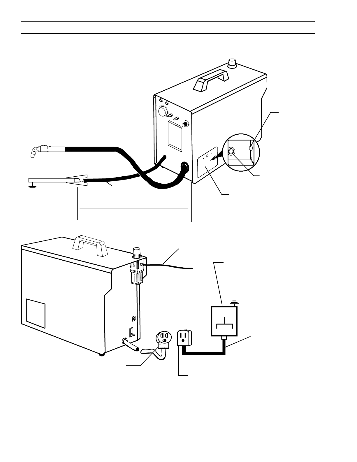
2.6 SECONDARY (OUTPUT) CONNECTIONS
(REFER TO FIG. 2-1)
Before making any connections to the power source
output terminals, make sure that all primary input
power to the power source is deenergized (off) at the
main disconnect switch and that the input power
cable is unplugged.
1. For operator safety, the torch connections are located on the output terminal board behind the lower
portion of the front panel. Remove access door to
Table 2.1. Recommended Sizes for Input Conductors and Line Fuses
output terminal board from right panel of power
source.
2. Thread the power cable and switch lead of the PT31XL through the right open bushing of the front
panel. Connect power cable to the torch fitting (lefthand threads) and plug in the switch lead to the torch
switch receptable on the output terminal board.
Make sure the power cable connection is wrenchtight. Make sure plug of switch lead is firmly locked
in place.
3. Reassemble the access door to the power source.
4. Connect your air supply to the inlet connection of the
filter-regulator.
5. Clamp the work cable to the workpiece. Be sure the
workpiece is connected to an approved earth ground
with a properly sized ground cable.
Rated Input Input & GND Fuse Size
Conductor Amps
Volts Amp Phases CU/AWG*
208 30 1 No. 10 40
230 25 1 No. 10 40
380 8/ph. 3 No. 12 15
415 7.5/ph. 3 No. 12 15
* Sized per National Code for 80°C rated copper conductors @ 30°C ambient. Not more than three
conductors in raceway or cable. Local codes should be followed if they specify sizes other than those
listed above.
11
SECTION 2 INSTALLATION
TORCH
POWER CABLE
CONNECTION
PT-31XL
WORK
SAFETY
GROUND
WORK CABLE
Allow at least 10 ft (3 m)
between work and power
source
TORCH SWITCH
RECEPTACLE
ACCESS DOOR FOR
TORCH CONNECTION.
Prefiltered AIR SUPPLY (Customer Supplied)
(90 to 150 psig max)
CUSTOMER FUSED LINE
DISCONNECT SWITCH
(See Table 2.1 and WARNING in
regards to chassis ground in Section 2.5.)
NOTE: If using 208 V input,
see Section 2.7 and
Fig. 2-2.
See Table 2.1
12
PLUG
(Equipped only on
230 V, 1-phase units)
RECEPTACLE (P/N 674540)
(Optional for 208/230 V, 1-phase
power sources)
Figure 2-1. PCM-500i Interconnection Diagram
SECTION 2 INSTALLATION
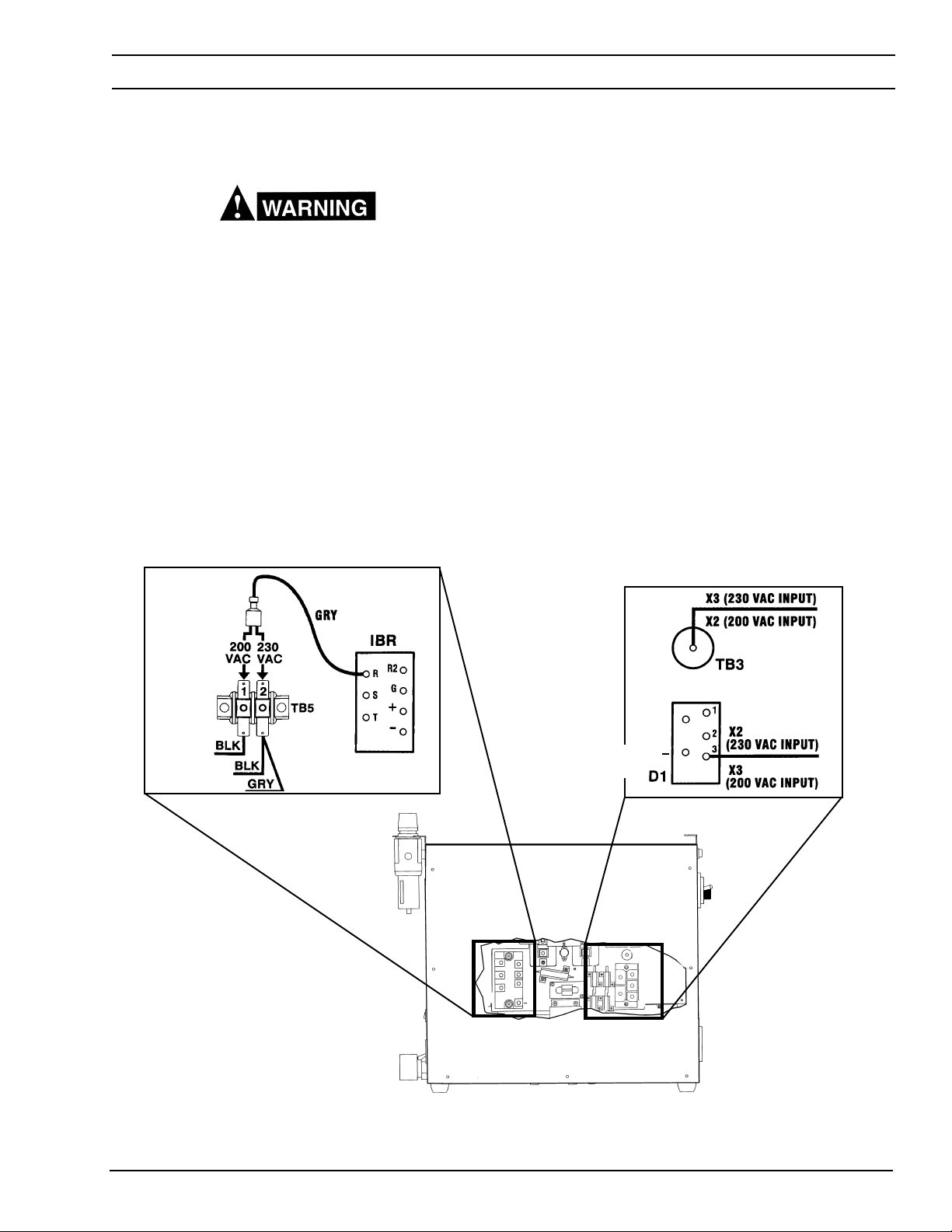
2.7 CONNECTING PCM-500I FOR 208 VAC INPUT
ELECTRIC SHOCK CAN KILL! Precautionary measures should be taken to provide maximum protection against electrical shock. Be sure that all power
is off by opening the line (wall) disconnect switch
and by unplugging the power cord to the unit when
reconnecting for 208 Vac input.
The PCM-500i power source with 208/230 vac, 1-phase
input capability is factory set for 230 vac input. If using
208 vac input, the PCM-500i must be reconnected as
follows before connecting to your input power.
Fig. 1
1. Remove cover from the PCM-500i power source.
2. Locate the input bridge (IBR) and the two-position
terminal block on the left side of the unit towards the
rear panel (see Fig. 1). Locate the gray wire connected to TB5-2 and to IBR terminal "R". For 108
Vac input, disconnect the gray wire from TB5-2 and
then firmly connect it to TB5-1.
3. Locate the output bridge (D1) on the left side towards the front panel (see fig. 2). Disconnect and
swap leads X2 and X3 from the main transformer.
For 208 Vac input, X2 is connected to TB3 and X3
is connected to terminal 3 of D1. Make sure the
connections are firmly tightened.
4. Leave all other wires the same.
5. Reinstall cover and connect the PCM-500i to the
208vac input power.
Fig. 2
INPUT BRIDGE
OUTPUT
BRIDGE
D1
+
~
~
Figure 2.2. Original Factory Setup for 230 Vac Input on
Power Source with 208/230 Vac Input Power Capability
13

SECTION 2 INSTALLATION
EARTH GROUND
DO NOT ATTACH WORK
WORK CABLE
CABLE TO PIECE BEING CUT
FREE
EARTH GROUND
GROUNDED
WORK TABLE
BE SURE WORK IS IN GOOD
CONTACT WITH TABLE.
14
WORK CABLE
Figure 2-3. Ground and Work Cable Connections

SECTION 3 OPERATION
3.1 OPERATION
ELECTRIC SHOCK can kill.
• Do NOT operate the unit with the cover removed.
• Do NOT apply power to the unit while holding or
carrying the unit.
• Do NOT touch any torch parts forward of the torch
handle (nozzle, heat shield, electrode, etc.) with
power switch on.
ARC RAYS can burn eyes and skin;
NOISE can damage hearing.
• Wear welding helmet with No. 6 or 7 lens shade.
• Wear eye, ear, and body protection.
Position the PCM-500i at least 10 feet (3 meters) from
the cutting area. Sparks and hot slag from the cutting operation can damage the unit.
3.2 PCM-500i CONTROLS (FIGURE 3-1)
A. Power Switch (located on rear panel). When
placed in ON position, the white pilot light will glow
indicating control circuit is energized and the cooling fan will run.
B. Output Current Control. Adjustable from 10 to
35 amperes to suit cutting conditions.
C. Air Check Switch. When placed in ON position,
air filter-regulator can be adjusted to desired pressure (65-75 psig) before cutting operations. Allow
air to flow for a few minutes. This should remove
any condensation that may have accumulated
during shutdown period. Be sure to place switch
in OFF position before starting cutting operations.
D. Lock-In Switch. When placed in ON position,
permits releasing torch switch button after cutting
arc has been initiated. To extinguish arc at end of
cut, press and release torch switch button again or
pull torch away from work. When placed in OFF
position, torch switch must be held closely by the
operator during the entire cutting operation and
then released at the end of cut.
FAULT LIGHT (AMBER)
POWER LIGHT (WHITE)
AIR PRESSURE
GAUGE
AIR CHECK
SWITCH
LOCK-IN
SWITCH
CURRENT
CONTROL KNOB
AIR REGULATOR
CONTROL KNOB
REAR
VIEW
CIRCUIT
BREAKER (3A)
POWER ON-OFF
(I-O) SWITCH &
CIRCUIT BREAKER
Figure 3-1. PCM-500i Controls
15

SECTION 3 OPERATION
E. Fault Light. Will glow amber under the following
conditions and operations will come to a complete
stop.
Flow Fault: The fault light will be mostly on but
will flick off for about 1/10th of a second every
second. This indicates that the air flow supply is
low.
Over Temperature: The fault light will be mostly
off but will flick on for about 1/10th of a second
every second. This indicates that the duty cycle
has been exceeded. Allow the power source to
cool down before returning to operate.
High/Low Line Voltage: The fault light will rapidly blink on and off (five times per second). This
indicates that the input voltage is outside the “+ or
-” 15% range of the input rating.
Over-Current: The fault light will be on continuously. This indicates that input current has been
exceeded.
All fault signals will remain on for a minimum
of 10 seconds. If fault clears, all will reset
automatically except for over-current. To clear
over-current, the power must be shut off for 5
seconds and then turned back on.
3.3 ASSEMBLING PT-31XL COMSUMABLE
PARTS
Make sure power switch on power source is in OFF
position and primary input power is deenergized.
To assemble “XT” consumables, remove the seat
supplied with the torch. Insert the plunger into the head.
(The plunger is reversible.) Then reassemble the seat
firmly with a wrench. Install the electrode, baffle, nozzle,
and heat shield as shown in Fig. 3-2. Tighten heat shield
snugly but do not overtighten.
20324
19679
20862
20463
21008
20282
NOTE: If cutting at less than 20 amps, standard
consumables illustrated below in Figure 3-2A
are recommended. These consumables are
supplied in Spare Parts Kit, P/N 19676. Air
presssure should be set at 40 to 50 psig.
ELECTRODE
13205
SWIRLBAFFLE
18785
Fig. 3-3A - Assembly of Standard Consumable Parts
NOZZLE
19667
HEAT SHEILD
20282
BE SURE to install the swirl baffle in the torch.
Failure to do so would allow the nozzle (tip) to
contact the electrode. This contact would permit
high voltage to be applied to the nozzle. Your contact
with the nozzle or workpiece could then result in
serious injury or death by electric shock.
The PT-31XL torch head contains a gas flow check
valve that acts in conjunction with the flow switch
and circuitry within the power source. This system
prevents the torch from being energized with high
voltage if the torch switch is accidentally closed
when the hield is removed. ALWAYS REPLACE
TORCH WITH THE PROPER TORCH MANUFACTURED BY ESAB SINCE IT ALONE CONTAINS
ESAB’S PATENTED SAFETY INTERLOCK.
For additional torch information, see booklet (F-14-246)
packed with the PT-31XL torch.
3.4 CUTTING WITH THE PT-31XL
Wear the usual protective gloves, clothing, and helmet. Helmet with filter lens shade No. 6 or 7 should
provide adequate protection for your eyes.
Plunger
NOTE: Nozzles
Marked By
Amperage
Fig. 3-2 - Assembly of “XT” Consumable Parts
16
Seat
Electrode
Baffle
Nozzle
35/40A
Heat Shield
Never touch any parts forward of the torch handle
(tip, heat shield, electrode, etc.) unless the power
switch is in the OFF position.

SECTION 3 OPERATION
WHEN THE ARC BREAKS
TO START A PIERCE, TILT THE
1
TORCH TO PREVENT MOLTEN MATERIAL FROM COMING BACK
AGAINST AND DAMAGING THE
TORCH.
2
THROUGH THE WORK,
THE TORCH TO AN UPRIGHT
POSITION AND PROCEED TO
CUT.
BRING
Figure 3-4. Piercing Technique using the PT-31XL
CAUTION: Do not depress the torch switch unless the
torch nozzle is touching or within 0.020-in.
(less than 1/32-in.) of the workpiece.
CAUTION: Locate the console at least 10-ft. from the
cutting work area. Chips and hot slag from
the cutting operation can damage the console.
After placing the primary (wall) switch to the ON position
TOO FAST TOO SLOW CORRECT
Fig. 3-3 - Effect of Cutting Speed
Cutting Speed Range — PCM-500i
(Using Air with XT Consumables @ 75 psi)
Output Cutting
Thickness Current Speed
Material (In.) (Amps) (ipm)
Carbon 1/16 30 180
Steel 1/8 30 75
(AISI 1020) 1/8 35 85
1/4 35 30
3/8 35 15
1/2 35 12
Stainless 1/16 30 200
Steel 1/8 30 85
(AISI 304) 1/8 35 85
1/4 35 30
3/8 35 14
1/2 35 10
Aluminum 1/16 30 200
(6061) 1/8 30 85
1/8 35 85
1/4 35 30
3/8 35 15
1/2 35 12
and making control and air pressure adjustments as
described above, proceed as follows:
1. Touch the tip of the torch to the workpiece (or within
0.020-in. of the workpiece) holding the torch at about
15- 30° angle to avoid damaging the tip.
NOTE: The speeds given here are typical for best quality cuts. Your actual
speeds may vary depending on material composition, surface condition, operator technique, etc. If cutting speed is too fast, you may lose
the cut. With slower speeds excessive dross may accumulate. If speed
is too slow, the arc may extinguish. Air cutting typically produces a
rough face on stainless steel and aluminum.
17

SECTION 3 OPERATION
2. Depress the torch switch. (Air and high frequency
should energize.)
3. Two seconds after depressing torch switch, the plasma
arc will start cutting. (If using the LOCK-IN mode,
torch switch can be released after establishing the
cutting arc.)
4. After starting the cut, the tip can be dragged along the
workpiece if cutting up to 1/4'’ thick material. When
cutting material greater than 1/4'’, maintain a 1/8'’ tipto-work (standoff) distance.
5. When ending a cut, the torch switch should be re-
leased (press and release if using LOCK-IN mode)
and lifted off the workpiece just before the end of the
cut to minimize double-arcing which can damage the
tip. This is to prevent high frequency from reigniting
after cutting arc extinguishes.
6. In the postflow mode, the arc can be restarted imme-
diately by depressing the torch switch. The two second preflow will automatically cancel.
3.5 OPERATING TECHNIQUES
1. Piercing - Materials (up to 1/4-in. thick) may be
pierced with the torch touching the work. When piercing thicker materials (up to 3/16-in. aluminum or 1/4in. stainless or carbon steel) immediately raise the
torch to 1/16-in. standoff after initiating the cutting arc.
This will reduce the chance of spatter from entering
the torch and prevent the possibility of welding the tip
to the plate. The torch should be angled at about 30°
when starting to pierce, and then straightened after
accomplishing the pierce.
2. Grate Cutting - For rapid restarts, such as grate or
heavy mesh cutting, do not release the torch switch.
This avoids the 2 second preflow portion of the cutting
cycle.
3.6 COMMON CUTTING PROBLEMS
Listed below are common cutting problems followed by
the probable cause of each. If problems are determined
to be caused by the PCM-500i, refer to the maintenance
section of this manual. If the problem is not corrected
after referring to the maintenance section, contact your
ESAB representative.
A. Insufficient Penetration.
1. Cutting speed too fast.
2. Damaged cutting nozzle.
3. Improper air pressure.
B. Main Arc Extinguishes.
Cutting speed too slow.
C. Dross Formation. (In some materials and thick-
nesses, it may be impossible to get dross-free
cuts.)
1. Cutting speed too fast or too slow.
2. Improper air pressure.
3. Faulty nozzle or electrode.
D. Double Arcing. (Damaged Nozzle Orifice.)
1. Low air pressure.
2. Damaged cutting nozzle.
3. Loose cutting nozzle.
4. Heavy spatter.
E. Uneven Arc.
Damaged cutting nozzle or worn electrode.
F. Unstable Cutting Conditions.
1. Incorrect cutting speed.
2. Loose cable or hose connections.
3. Electrode and/or cutting nozzle in poor condition.
G. Main Arc Does Not Strike.
Loose connections.
H. Poor Consumable Life.
1. Improper gas pressure.
2. Contaminated air supply.
18

SECTION 4 MAINTENANCE
4.1 GENERAL
If this equipment does not operate properly, stop
work immediately and investigate the cause of the
malfunction. Maintenance work must be performed
by an experienced person, and electrical work by a
trained electrician. Do not permit untrained persons
to inspect, clean, or repair this equipment. Use only
recommended replacement parts.
Be sure that the wall disconnect switch or wall
circuit breaker is open before attempting any inspection or work inside of the PCM-500i.
4.2 INSPECTION AND CLEANING
Frequent inspection and cleaning of the PCM-500i is
recommended for safety and proper operation. Some
suggestions for inspecting and cleaning are as follows:
A. Check work cable to workpiece connection.
H. With all input power disconnected, and wearing
proper eye and face protection, blow out the inside
of the PCM-500i using low-pressure dry compressed air.
4.3 FLOW SWITCH (FIGURE 4-1)
When excessive contamination is found in the air, the
flow switch (FS) should be removed, disassembled and
cleaned as follows:
A. Ensure the system is shut down and there is no
trapped air under pressure in the piping.
B. Remove the piston plug.
C. Remove the spring (FS-4 only). Use care when
handling spring to prevent distortion.
D. Remove the piston.
E. Clean all parts with cleaning agent.
NOTE
Ensure cleaning agent does not contain solvents
which can degrade polysulfone. Warm water and
detergent is recommended for cleaning. Allow all
parts to dry thoroughly before reassembly.
B. Check safety earth ground at workpiece and at
power source chassis.
C. Check heat shield on torch. It should be replaced
if damaged.
D. Check the torch electrode and cutting nozzle for
wear on a daily basis. Remove spatter or replace
if necessary.
E. Make sure cable and hoses are not damaged or
kinked.
F. Make sure all fittings and ground connections are
tight.
Water or oil occasionally accumulates in compressed
air lines. Be sure to direct the first blast of air away
from the equipment to avoid damage to the PCM500i.
Reassemble the flow switch in reverse order.
PISTON PLUG
SPRING
PISTON
FLOW SWITCH
Figure 4-1. Disassembly / Assembly of Flow Switch
19

SECTION 5 TROUBLESHOOTING
5.1 TROUBLESHOOTING
ELECTRIC SHOCK CAN KILL! Be sure that all primary power to the machine has been externally
disconnected. Open the line (wall) disconnect switch
or circuit breaker before attempting inspection or
work inside of the power source.
Check the problem against the symptoms in the following troubleshooting guide. The remedy may be quite
simple. If the cause cannot be quickly located, shut off
the input power, open up the unit, and perform a simple
visual inspection of all the components and wiring.
Check for secure terminal connections, loose or burned
wiring or components, bulged or leaking capacitors, or
any other sign of damage or discoloration.
The cause of control malfunctions can be found by
referring to the sequence of operations and electrical
schematic diagram (Figure 5-1) and checking the various components. A volt-ohmmeter will be necessary for
some of these checks.
Voltages in plasma cutting equipment are high
enough to cause serious injury or possibly death. Be
particularly careful around equipment when the covers are removed.
NOTE
Before checking voltages in the circuit, disconnect the
power from the high frequency generator to avoid damaging your voltmeter.
5.2 TROUBLESHOOTING GUIDE
A. Difficult Starting.
• Change electrode
• Change nozzle
• Check for good, clean connection of work lead to workpiece
• Check air pressure (65 - 75 psig)
• Check torch power cable for continuity
Depress torch switch. After 2 seconds, is high frequency present?
Yes
Repair power
source
No
Repair/replace
high frequency
unit
20

SECTION 5 TROUBLESHOOTING
B. No Air
Is air hose connected?
Yes No Connect
Is air adjusted to 65 - 75 psig?
Yes No Adjust
Does air come on with air check switch?
Yes No • No electrode in torch
• No valve pin in torch
• Replace electrode
Check continuity of torch switch • Replace valve pin
OK No Replace torch switch
Repair power source
21

SECTION 5 TROUBLESHOOTING
C. Air does not shut off
Is air check switch OFF?
Yes No Turn switch OFF
Does arc start when nozzle contacts work without depressing torch switch?
Yes No
Check for short in torch switch
Does air flow even when PCM-500i power switch is OFF?
Yes No
Replace Repair power
solenoid valve source
22

SECTION 5 TROUBLESHOOTING
D. White "Power" light not energized.
Is main 230 volt switch ON?
Yes No Turn on main disconnect
Is plug in receptacle?
Yes No Insert plug in receptacle
Is cooling fan turning?
Yes No
Replace
pilot light
Check voltage at receptacle and input power line
Yes No Check main fuses
Faulty power
switch on PCM-500i
23

SECTION 5 TROUBLESHOOTING
E. Amber "FAULT" light ON.
Is the unit overheated?
("Fault" lights turns off
when Unit cools down.)
Yes No
Is air flowing?
Duty cycle exceeded:
40% @ 35 A, 60% @ 30 A, Yes No
or 100% @ 22 A output
See page 5-2
Is input voltage within ±15% of units input rating?
Yes No
Adjust voltage • Repair power source
•
Fault light will energize if input voltage goes below or above ±15% of units input rating. The light will not turn
OFF even when correct voltage is restored. Reset by placing PCM-500i power switch OFF and then ON
again.
NOTE: When in LOCK-IN mode, the FAULT light will turn on during second "trigger". This does not affect
performance. Turn off.
24

SECTION 5 TROUBLESHOOTING
5.3 SEQUENCE OF OPERATION
A. LOCK-IN "OFF" position
TORCH SWITCH
PUSH RELEASE
OPEN CLOSE
GAS SOLENOID VALVE
2 SEC.
FLOW SWITCH CLOSE
FAULT OVERLOAD LIGHT
ENERGIZE
HF CIRCUIT
PREFLOW
10 SEC
Postflow
OPEN
INVERTER
CUTTING ARC (CURRENT)
NOTES:
1. When the torch switch is pushed during postflow period, the postflow and preflow times are canceled, and the HF
is energized immediately.
2. When the amber fault pilot light comes on, cutting operation should be stopped. The postflow time starts from the
moment the torch switch is released.
25

SECTION 5 TROUBLESHOOTING
B. LOCK-IN "ON" position
PUSH RELEASE PUSH RELEASE
TORCH SWITCH
OPEN CLOSE
GAS SOLENOID VALVE
2 SEC.
CLOSE OPEN
FLOW SWITCH
PREFLOW
10 SEC
Postflow
POSTFLOW
FAULT PILOT LIGHT
ENERGIZE
HF CIRCUIT
INVERTER
CUTTING ARC (CURRENT)
NOTES:
1. When the torch switch is pushed during postflow period, the postflow and preflow times are canceled, and the HF
is energized immediately.
2. When the amber fault pilot light comes on, cutting operation should be stopped. The postflow time starts from the
moment the torch switch is released.
3. FAULT pilot light is on during second "turn-off" trigger only. This does not affect performance in any way.
26

Figure 5-1. Schematic Diagram PCM-500i, 200/230 Vac, 50/60 Hz, 1-Phase
Units, see Supplement F-15-395
D-36338-E
NOTE: For 220 V, 1- and 3-phase CE
27
D-36403-G (Sheet 1)
28
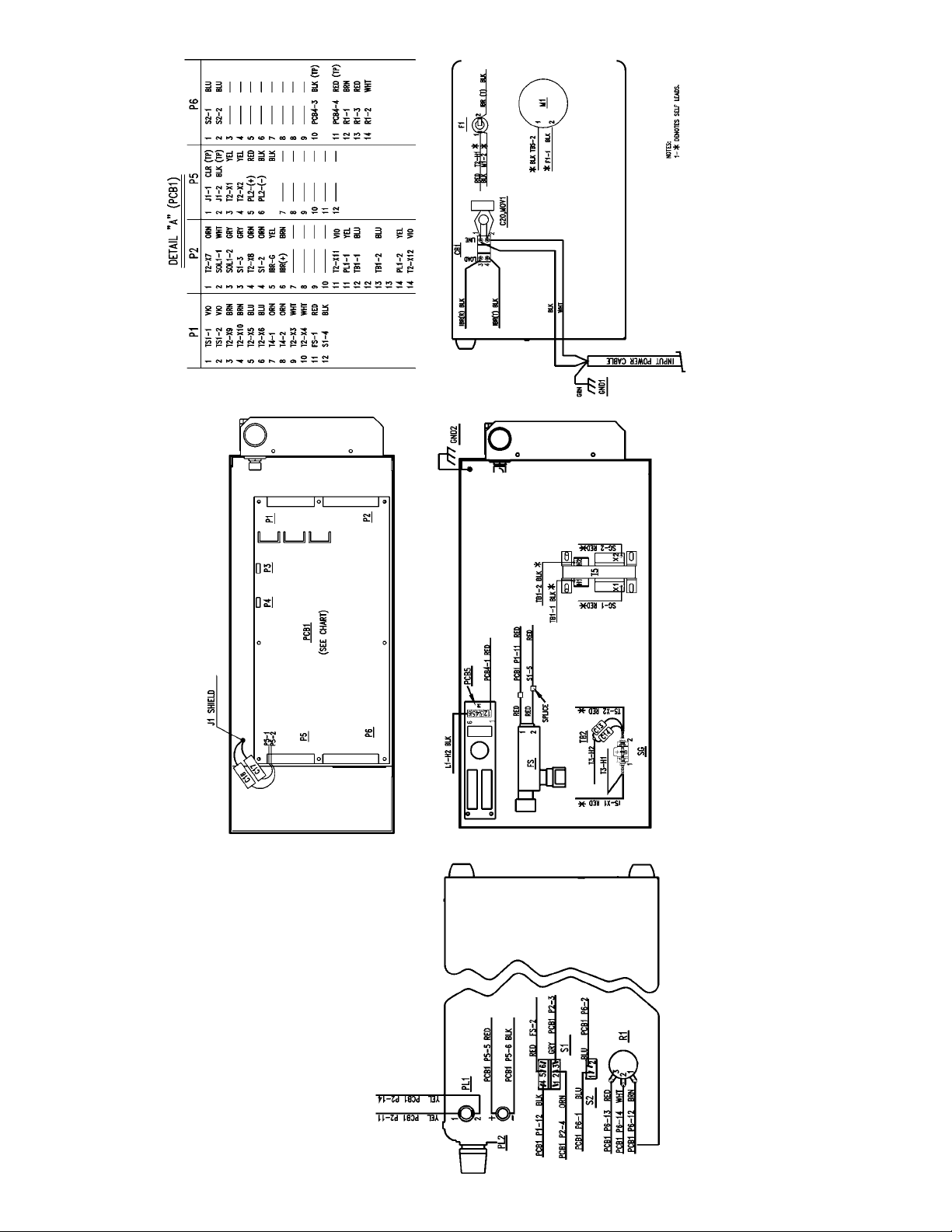
Figure 5-2. Wiring Diagram - PCM-500i 200/230 Vac, 50/60 Hz, 1-Phase (Sheet 1)

Figure 5-2. Wiring Diagram - PCM-500i 200/230 Vac, 50/60 Hz, 1-Phase (Sheet 2)
D-36403-G (Sheet 2)
29

D-36339-E
30
Figure 5-3. Schematic Diagram - PCM-500i 380/415 Vac, 50/60 Hz, 3-Phase

D-36524-E (Sheet 1)
Figure 5-4. Wiring Diagram - PCM-500i 380/415 Vac, 50/60 Hz, 3-Phase (Sheet 1)
31

D-36524-E (Sheet 2)
32
Figure 5-4. Wiring Diagram - PCM-500i 380/415 Vac, 50/60 Hz, 3-Phase (Sheet 2)

SECTION 6 REPLACEMENT PARTS
6.1 GENERAL
Replacement Parts are illustrated on the following figures. When ordering replacement parts, order by part
number and part name, as illustrated on the figure.
Figures 6-1 through 6-4 show replacement parts for the
following PCM-500i Power Source Assemblies:
208/230 Vac, 1-phase - P/N 36304 (ESAB)
400 Vac, 3-phase - P/N 36306 (ESAB)
Always provide the series or serial number of the unit on
which the parts will be used. The serial number is
stamped on the unit nameplate.
6.2 ORDERING
To assure proper operation, it is recommended that only
genuine ESAB parts and products be used with this
equipment. The use of non-ESAB parts may void your
warranty.
Replacement parts may be ordered from your ESAB
distributor or from:
ESAB Welding & Cutting Products
Attn: Customer Service Dept.
PO Box 100545, Ebenezer Road
Florence, SC, 29501-0545
Be sure to indicate any special shipping instructions
when ordering replacement parts.
To order parts by phone, contact ESAB at 1-843-664-
5540. Orders may also be faxed to 1-800-634-7548. Be
sure to indicate any special shipping instructions when
ordering replacement parts.
Refer to the Communications Guide on back cover of this
manual for a list of customer service phone numbers.
33

SECTION 6 REPLACEMENT PARTS
11
18
12, 14
13
8
7, 14
9
6
5
4
2, 3
18
1
17
19
10
16
15
Figure 6-1. Front View, PCM-500i
ITEM QTY. PART CIRCUIT
NO. REQ. NO. DESCRIPTION SYMBOL
1 1 35946 CHASSIS
2 1 2062018 POTENTIOMETER 10K 2W R1
3 1 13730611 KNOB
4 1 35947YL COVER TOP
5 1 954707 WARNING LABEL
6 1 951575 HANDLE (Screws and Lockwashers included)
7 1 634518 SWITCH TOGGLE DPDT 2POS 15A S1
8 1 951526 LAMP, WHITE PL2
9 1 951754 LAMP, YELLOW PL1
10 2 993426 GROMMET 1.5" ID
11 1 21711 GAUGE PRESSURE
12 1 673213 SWITCH TOGGLE SPST 2 POS 15A S2
13 1 23602576 STRAIN RELIEF
14 2 951474 SWITCH SEAL
15 4 182W12 FOOT
16 1 36330YL ACCESS DOOR (ESAB)
1 36330LG ACCESS DOOR (L-TEC)
17 1 2091514 WARNING LABEL
18 2 13734588 LABEL (ESAB)
19 1 954008 WARNING LABEL, HI-VOLTAGE
34

SECTION 6 REPLACEMENT PARTS
43
52
42
41
39
40
38
37
36
35
32, 33, 34
51
31
44
45, 46
ITEM QTY. PART CIRCUIT
NO. REQ. NO. DESCRIPTION SYMBOL
31 1 951179 HI VOLTAGE TRANSFORMER T5
32 1 950487 TERMINAL BLOCK 2 POS TB1
33 1 950204 CAPACITOR 0.1µf 250 VAC C9
34 2 672348 CAPACITOR 0.01µf 1 KV C11, C12
35 2 950823 SNAP BUSHING
36 1 35940 CONTROL TRANSFORMER T2
37 1 951182 FAN AC AXIAL M1
38 1 21698 AIR LINE FILTER REGULATOR
39 1 35945 INDUCTOR POWER FACTOR CORRECTION (230V) L2
40 1 92W57 GROMMET -.63" ID
41 1 35941 MAIN TRANSFORMER T1
42 1 952606 INDUCTOR OUTPUT L1
43 1 680560 WORK CABLE 25 FT includes CLAMP 13730862
44 1 182W64 RECEPTACLE, TWIST LOCK MIDGET J1
45 1 36333 OUTPUT TERMINAL BOARD
46 1 58V75 ADAPTOR B/A 1/4 NPTM BULKHEAD
47 1 32969 REACTOR HI FREQ T3
48 1 36431 SPARK GAP ASS’Y includes (2) POINT 32931 SG
49 1 951569 STANDOFF TB2
50 2 951342 CAPACITOR 2500µf 15 KV C13, C14
51 1 952212 3%, 3-PH LINE REACTOR, 8A/PH (400 V) L2
* 1 951515 CAPACITOR 0.047µf, 660 V (CE UNITS ONLY) C23
52
47
Figure 6-2. Right Side View, PCM-500i
49, 5048
* Not shown. See Wiring Diagram, Figure 5-4 for location.
35

SECTION 6 REPLACEMENT PARTS
67
71
67
64
65, 66
72
68, 69
70
65, 66
63
74
73
90
75, 88
76
86
77
78
79
81
82, 83
200/230 V, 1 Phase Power Source illustrated.
63
62
61
89
85
84
36

SECTION 6 REPLACEMENT PARTS
Figure 6-3. Left Side View, PCM-500i
ITEM QTY. PART CIRCUIT
NO. REQ. NO. DESCRIPTION SYMBOL
61 5 951313 CAPACITOR 0.01µF 1KV C5, 6, 7, 8, 10
62 1 952208 STANDOFF (230, 1-PHASE) TB3
63 2 673038 SNAP BUSHING
64 1 952147 HEATSINK
65 2 950518 GROMMET 2.12" ID
66 2 952185 CAPACITOR 1000µf 400 VDC (230V) C1, C2
67 4 17235150 RESISTOR 50K 12W (230 V) R2
2 17290210 RESISTOR 10K 20W (400 V) R2, R15
68 2 951205 IGBT 100 A 600 V (includes PAD 951190) (230 V) Q1, Q2
1 952175 DUAL MODULE IGBT 75 A 1200 V (incl. PAD 951191) (400 V) Q1
69 2 38014 PC BOARD IGBT DRIVER (230 V) PCB2, PCB3
1 38099 PC BOARD IGBT DRIVER (400 V) PCB3
70 2 36404 BUSBAR (230 V)
1 36425 BUSBAR (400 V)
71 2 951940 CAPACITOR 1µf 600 VDC (230 V) C15, C16
1 951917 CAPACITOR .5µf 1200 VDC (400 V) C22
72 1 951028 CAPACITOR 1µf 630 VDC (230 V) C3
2 951028 CAPACITOR 1µf 630 VDC (400 V) C3, C15
73 1 951085 THERMAL SWITCH D/T 176 15 A 120 V TS1
74 1 2062282 CAPACITOR 0.22µf 1KV C19
75 1 952149 MODULE INPUT BRIDGE 50 A (includes PAD 951191) IBR
76 2 17750010 RESISTOR 50 W 10 OHM (PAD 951194) R7, R10
77 1 32958 CURRENT TRANSFORMER T4
78 1 951161 CAPACITOR 20µf 400 VDC C4
79 1 17145339 RESISTOR 39 K 2 W R9
80 1 951202 FLOW SWITCH 2.5 SCFM SPST FS
81 4 17721020 RESISTOR 20 OHM 25 W (PAD 951193) R3, 4, 5, 6
82 1 950249 SOLENOID VALVE 1/4 NPT 24 VAC SOL1
83 1 951471 ZENER DIODE 60 V 75 mA ZD1
84 1 952150 OUTPUT BRIDGE MODULE (includes PAD 951192) D1
85 1 38092 PC BOARD ASSY’S START UP (hidden) PCB5
86 1 647361 TERMINAL LUG GROUND (hidden) GND1
88 3 950591 VARISTOR METAL OXIDE 510 (400 V) MOV 1, 2, 3
89 1 952002 CORE SATURABLE L3
90 1 950487 TERMINAL BLOCK 2 POS (230 V ONLY) TB5
37

SECTION 6 REPLACEMENT PARTS
103
104, 105, 106
Top View
102
Rear View
114
101
108
113, 117
110, 111, 112
101
107
Figure 6-4. Top and Rear View, PCM-500i
ITEM QTY. PART CIRCUIT
NO. REQ. NO. DESCRIPTION SYMBOL
101 2 92W57 GROMMET 0.63 ID
102 2 951469 CAPACITOR 0.22µf 250 VAC C17, C18
103 1 31488 PC BOARD SHUNT PCB4
104 1 38086 PC BOARD ASS’Y CONTROL (230 V) PCB1
1 38087 PC BOARD ASS’Y CONTROL (400 V) PCB1
105 8 950708 SUPPORT, PC BOARD
106 1 23604891 WARNING LABEL HI VOLTAGE
107 1 10Z30 ADAPTOR, AIR-WATER
108 1 993426 GROMMET 1.5" ID (cut into 2 equal halves)
110 1 952176 CIRCUIT BREAKER 40 A (208/230 v, 1 ph) CB1
1 952178 CIRCUIT BREAKER 15 A (ALL 3 PH) CB1
111 1 951470 CAPACITOR 0.047µf 300 VAC (208/230 V, 1 PH) C20
112 1 951321 VARISTOR METAL OXIDE (208/230 V, 1 PH) MOV1
113
1 952559 FUSE 3A 600VAC FAST ACTING F1
114 1 954555 LABEL RATING, 208/230 V 1 PH, ESAB
1 954616 LABEL RATING, 400 V 3 PH, ESAB
115 1 13734727 STRAIN RELIEF
116 1 34574 CABLE INPUT POWER w/PLUG 10 FT (208/230 V)
1 35582 CABLE INPUT POWER, 10 FT (3-PH UNITS)
117 1 952136 FUSE HOLDER
115
116
Units made prior to May, 1997 were equipped wiith 3A circuit breaker 950829.
38

The "B" edition of (10/98) of this manual covers the following changes that have occurred between May, 1997 (Serial
No. PX-I618001) and September, 1998:
1. Removed the L-TEC and the European CE labeled packages. L-TEC units were discontinued. CE units are now
covered in F-15-417 and F-15-424.
2. TB5 Terminal Block (950487) was added to simplify reconnection from 230Vac input to 208Vac.
3. Changed L1 Output Inductor 32909 to 952606 and in series with torch switch leads from J1 to PCB to provide more
protection for the PCB.
4. Added saturable core output Inductor (952002) for improved performance.
5. Thermal Pads are now included with IBGT's and Bridge Modules.
6. On the 208/230Vac units, the Q1 and Q2 50A IGBT's (952148) was changed to 100A IGBT (951205).
7. On the 208/230Vac units, the 10-ft. Input Power Cable (34574) was changed to 6-ft. cable (36673).
The "C" edition (1/02) of this manual covers the following changes:
1. Wiring Diagram 36403 has been updated.
2. Item 116 (P/N 36673) was changed to (P/N 34574) and the Plug (208/230 V) was changed from 6 Ft. to 10 Ft.
The "D" edition (06/03) of this manual covers the following changes:
1. Item 80 Description on Page 37 was changed from 0.25 GPM to 2.5 SCFM.
The "E" edition (02/04) of this manual covers the following changes:
1. Revised Spare Parts Kit from 21980 to 0558003301.
39

ESAB Welding & Cutting Products, Florence, SC Welding Equipment
COMMUNICATIONS GUIDE - CUSTOMER SERVICES
A. CUSTOMER SERVICE QUESTIONS: Telephone (843) 664-5540/Fax: (800) 634-7548
Order Entry Product Availability Pricing Hours: 8:30 AM to 5:00 PM EST
Order Changes Saleable Goods Returns Delivery
Shipping Information
B. ENGINEERING SERVICE: Telephone: (843) 664-4416 / Fax : (800) 446-5693
Welding Equipment Troubleshooting Hours: 7:30 AM to 5:00 PM EST
Warranty Returns Authorized Repair Stations
C. TECHNICAL SERVICE: Telephone: (800) ESAB-123/ Fax: (843) 664-4452
Part Numbers Technical Applications Hours: 8:00 AM to 5:00 PM EST
Performance Features Technical Specifications Equipment Recommendations
D. LITERATURE REQUESTS: Telephone: (843) 664-5501 / Fax: (843) 664-5548
E. WELDING EQUIPMENT REPAIRS: Telephone: (843) 664-4469 / Fax: (843) 664-5557
Repair Estimates Repair Status Hours: 7:30 AM to 3:30 PM EST
F. WELDING EQUIPMENT TRAINING:
Telephone: (843)664-4428 / Fax: (843) 664-4476
Training School Information and Registrations Hours: 7:30 AM to 4:00 PM EST
G. WELDING PROCESS ASSISTANCE:
Telephone: (843) 664-4248 Hours: 7:30 AM to 4:00 PM EST
H. TECHNICAL ASST. CONSUMABLES:
Telephone: (800) 934-9353 Hours: 7:30 AM to 5:00 PM EST
Hours: 7:30 AM to 4:00 PM EST
IF YOU DO NOT KNOW WHOM TO CALL
Telephone: (800) ESAB-123/ Fax: (843) 664-4452/Web: http://www.esab.com
Hours: 7:30 AM to 5:00 PM EST
F15-296-E 02 / 2004 Printed in U.S.A.
 Loading...