

Page 1

7
1
PAB Device Profile
FIELDBUS
LAF/TAF and Aristo 1000
Page 2

7
2
1 GENERAL ............................................................................................................ 8
2 REFERENCES ..................................................................................................... 9
3 ABBREVIATIONS AND DEFINITIONS ................................................................ 9
4 REVISION HISTORY ............................................................................................ 9
5 FIELDBUS INTRODUCTION ............................................................................. 10
5.1 Profibus ......................................................................................................................... 10
5.1.1 Introduction to Profibus DP ..................................................................................... 10
5.1.2 Network overview ................................................................................................... 10
5.1.3 Technical features for Profibus DP / DPV1 ............................................................ 11
5.1.4 Mechanical Overview .............................................................................................. 12
5.1.5 Protocol and Supported Functions ........................................................................... 12
5.1.6 Physical Interface .................................................................................................... 12
5.1.7 Configuration and Indications ................................................................................. 12
5.1.8 Fieldbus Connectors ................................................................................................ 12
5.1.9 Configuration ........................................................................................................... 13
5.1.10 Indications ............................................................................................................ 14
5.2 Profinet .......................................................................................................................... 16
5.2.1 Introduction to PROFINET ..................................................................................... 16
5.2.2 Network overview ................................................................................................... 16
5.2.3 Technical features for PROFINET .......................................................................... 16
5.2.4 Mechanical Overview .............................................................................................. 16
5.2.5 Protocol and Supported Functions ........................................................................... 16
5.2.6 Physical Interface .................................................................................................... 16
5.2.7 Configuration and Indications ................................................................................. 17
5.2.8 Fieldbus Connectors ................................................................................................ 17
5.2.9 Configuration ........................................................................................................... 17
5.2.10 Indications ............................................................................................................ 18
6 USB MEMORY ................................................................................................... 19
6.1 Configuration File ........................................................................................................ 19
6.2 Web Interface ............................................................................................................... 20
6.3 Fieldbus information .................................................................................................... 20
6.4 Import and Export Directory (external USB) ........................................................... 21
7 BASIC SETUP ................................................................................................... 22
7.1 Motor Configuration .................................................................................................... 22
7.2 Unit of Length ............................................................................................................... 23
Page 3
7
3
8 FUNCTIONAL I/O DATA MAP ........................................................................... 24
8.1 In I/O from Controller to Welding Equipment ......................................................... 24
8.1.1 Mapping of the command bytes .............................................................................. 26
Command LSB .................................................................................................. 26
Command MSB ................................................................................................ 27
Command 2 LSB ............................................................................................... 27
Command 2 MSB ............................................................................................. 27
8.1.2 Mapping of the set values ........................................................................................ 28
Method and Regulation ..................................................................................... 29
Voltage .............................................................................................................. 29
Current .............................................................................................................. 29
AC Frequency ................................................................................................... 30
AC Balance ....................................................................................................... 30
AC Offset .......................................................................................................... 30
AC Phase Shift .................................................................................................. 30
Start Adjust ....................................................................................................... 31
Regulation Dynamics ........................................................................................ 31
Regulation Inductance ...................................................................................... 31
8.2 Out I/O from Welding Equipment to Controller ...................................................... 32
8.2.2 Mapping of the status bytes ..................................................................................... 34
Status LSB: ....................................................................................................... 34
Status MSB: ...................................................................................................... 35
Status 2 LSB: .................................................................................................... 35
Status 2 MSB: ................................................................................................... 36
8.2.3 Mapping of the output values .................................................................................. 37
Number of Errors/Events .................................................................................. 38
Measured Voltage ............................................................................................. 38
Measured Current .............................................................................................. 38
Measured Heat Input ......................................................................................... 38
Set Method and Regulation ............................................................................... 39
Set AC Frequency ............................................................................................. 39
Set AC Balance ................................................................................................. 40
Set Voltage ........................................................................................................ 40
Set Current ........................................................................................................ 40
Set AC Offset .................................................................................................... 40
Set AC Phase Shift ............................................................................................ 40
Error Record ...................................................................................................... 41
Heart Beat Value ............................................................................................... 41
Set Start Adjust ................................................................................................. 41
Set Regulation Dynamics .................................................................................. 41
Set Regulation Inductance ................................................................................ 42
9 ASYNCHRONOUS COMMUNICATION ............................................................. 43
9.1 Asynchronous Communication Sequences ................................................................ 43
9.1.1 Read Sequence ......................................................................................................... 43
9.1.2 Write Sequence ........................................................................................................ 43
9.1.3 Error Codes .............................................................................................................. 43
Page 4

7
4
Profibus ............................................................................................................. 44
Profinet .............................................................................................................. 44
9.2 Functional Description of Asynchronous Communication ...................................... 45
9.2.1 Mapping of functions ............................................................................................... 46
Weld Process ..................................................................................................... 47
Method .............................................................................................................. 48
Regulation Type ................................................................................................ 49
Wire Type ......................................................................................................... 50
Wire Dimension ................................................................................................ 50
Voltage .............................................................................................................. 51
Current .............................................................................................................. 51
Start Type .......................................................................................................... 52
Crater Fill Time ................................................................................................. 52
Burn Back Time ................................................................................................ 53
Regulation Dynamics ........................................................................................ 53
Regulation Inductance ...................................................................................... 54
AC Frequency ................................................................................................... 54
AC Balance ....................................................................................................... 55
AC Offset .......................................................................................................... 55
AC Phase Shift .................................................................................................. 56
Start Adjust ....................................................................................................... 57
Cable Area ........................................................................................................ 57
Cable Length ..................................................................................................... 58
Get Wire Dimensions ........................................................................................ 58
Get Wire Types ................................................................................................. 60
Measure Value Frequency ................................................................................ 60
Max OCV .......................................................................................................... 61
Parallel Power Sources ..................................................................................... 61
Number of units in parallel ............................................................................... 62
AC Sync Master ................................................................................................ 62
Couple ID .......................................................................................................... 63
Pair Parallel Couple .......................................................................................... 63
Measure Value Filter ......................................................................................... 64
Tandem Role ..................................................................................................... 64
Unit of Length ................................................................................................... 65
Language selection ............................................................................................ 65
Calendar Year ................................................................................................... 66
Calendar Month ................................................................................................ 67
Calendar Day .................................................................................................... 67
Calendar Hour ................................................................................................... 68
Calendar Minute ................................................................................................ 68
Calendar Second ............................................................................................... 68
Get Connected Units ......................................................................................... 69
Get Node Information ....................................................................................... 70
Get Welding System ......................................................................................... 70
Import Settings/Data ......................................................................................... 71
Export Settings/Data ......................................................................................... 71
Get Error Message ............................................................................................ 72
Error device type ............................................................................................... 72
Page 5

7
5
Get Error Text ................................................................................................... 73
CAN2 Node ID ................................................................................................. 74
Get Connected Units CAN2 .............................................................................. 74
Get Node Information CAN2 ............................................................................ 74
10 ADVANCED USE ............................................................................................ 76
10.1 Weld data handling ................................................................................................... 76
10.1.1 Input Area Switching ........................................................................................... 76
Input Weld Data Area ....................................................................................... 76
Output Weld Data Area..................................................................................... 77
10.1.2 Weld Data Set ....................................................................................................... 78
Input Weld Data Set Data ................................................................................. 78
Output Weld Data Set Data ............................................................................... 79
10.1.3 Asynchronous Weld Data Set Functions .............................................................. 79
Weld Data Set Recall ........................................................................................ 79
Weld Data Set Save .......................................................................................... 80
Weld Data Set Delete ........................................................................................ 80
10.2 Motor Handling ......................................................................................................... 81
10.2.1 Input Motor Data .................................................................................................. 81
Command LSB .................................................................................................. 81
Command MSB ................................................................................................ 82
Set values .......................................................................................................... 83
10.2.2 Output Motor Data ............................................................................................... 84
Status LSB ........................................................................................................ 84
Status MSB ....................................................................................................... 85
Set values .......................................................................................................... 86
Measure values .................................................................................................. 87
10.2.3 Mapping of external motor data ........................................................................... 88
Requested Travel Speed .................................................................................... 88
Requested Wire Speed ...................................................................................... 88
10.2.4 Asynchronous Motor Functions ........................................................................... 89
Wire Speed ........................................................................................................ 89
Travel Speed ..................................................................................................... 90
Travel Direction ................................................................................................ 90
Creep Start ........................................................................................................ 91
Creep Speed ...................................................................................................... 91
Max Travel Speed ............................................................................................. 92
Travel Control (Aristo 1000 only) .................................................................... 92
Travel Motor Drive ........................................................................................... 93
Wire Feed Motor Scale Factors ........................................................................ 93
Jog Wire Feed Low Speed .............................................................................. 94
Jog Wire Feed High Speed.............................................................................. 95
Travel Motor Scale Factors ............................................................................. 95
Jog Travel High Speed .................................................................................... 96
10.2.5 Scale Factors for ESAB motors ........................................................................... 97
Wire Feed Motors ............................................................................................. 97
Travel Motors .................................................................................................... 97
Page 6

7
6
10.3 ICE Handling ............................................................................................................ 98
10.3.1 Input ICE data ...................................................................................................... 98
Command MSB ................................................................................................ 98
Set values .......................................................................................................... 99
10.3.2 Output ICE data .................................................................................................... 99
Status MSB ..................................................................................................... 100
Status 2 LSB ................................................................................................... 100
Status 2 MSB .................................................................................................. 101
Set values ........................................................................................................ 101
Measure values ................................................................................................ 101
10.3.3 Mapping of external ICE motor data .................................................................. 102
Requested ICE Wire Speed ............................................................................. 102
10.3.4 Asyncronous ICE Functions ............................................................................... 103
ICE Wire Speed Percentage ............................................................................ 103
ICE Active ...................................................................................................... 104
ICE Start Delay ............................................................................................... 104
ICE Wire Feed Motor Scale Factors ............................................................... 105
Jog ICE Wire Feed Low Speed ....................................................................... 106
Jog ICE Wire Feed High Speed ...................................................................... 106
ICE License remaining time ........................................................................... 107
11 TROUBLESHOOTING .................................................................................. 108
11.1 General ..................................................................................................................... 108
11.2 PAB ........................................................................................................................... 108
11.2.1 Fieldbus indications ............................................................................................ 108
11.2.2 Application program indications ........................................................................ 108
11.2.3 USB indications .................................................................................................. 110
11.2.4 Ethernet indications ............................................................................................ 111
11.3 Communication ....................................................................................................... 112
11.3.1 CAN bus ............................................................................................................. 112
11.3.2 Fieldbus .............................................................................................................. 113
11.4 PLC ........................................................................................................................... 115
11.4.1 Installation .......................................................................................................... 115
12 APPLICATION EXAMPLES .......................................................................... 116
12.1 Wire selection .......................................................................................................... 116
12.2 Motor Control ......................................................................................................... 117
12.2.1 FAA used for motor control ............................................................................... 117
12.2.2 External motor control ....................................................................................... 117
12.3 Single power source ................................................................................................ 118
12.4 Parallel power sources (single wire) ...................................................................... 119
12.5 Tandem power sources (two wires) ....................................................................... 120
Page 7

7
7
13 WEB INTERFACE ......................................................................................... 121
13.1 Weld Data Parameters ........................................................................................... 123
13.1.1 Main ................................................................................................................... 123
13.1.2 Start Data ............................................................................................................ 124
13.1.3 Stop Data ............................................................................................................ 125
13.1.4 Regulation Parameters ........................................................................................ 126
13.2 Configuration .......................................................................................................... 127
13.2.1 Main ................................................................................................................... 127
13.3 Machine Configuration .......................................................................................... 129
13.3.1 Wire Feed Axis ................................................................................................... 129
13.3.2 ICE Wire Feed Axis ........................................................................................... 130
13.3.3 Travel Axis ......................................................................................................... 131
13.3.4 Parallel PS .......................................................................................................... 132
13.3.5 Tandem ............................................................................................................... 133
13.4 Maintenance ............................................................................................................ 134
13.4.1 Unit Information ................................................................................................. 134
13.4.2 Event Handling ................................................................................................... 135
13.4.3 Export/Import Files ............................................................................................ 136
13.4.4 Calendar ............................................................................................................. 137
13.4.5 Memory .............................................................................................................. 138
13.4.6 Service Functions ............................................................................................... 139
14 ERRORS AND EVENTS ............................................................................... 140
Page 8

7
8
1 General
The PAB is a unit that acts as an interface between an external controller and ESAB
welding equipment. This document will describe the different ways to do this both
with set-up of the system and during welding.
In the tables you will sometimes see greyed-out areas, information about these can
be found in Advanced use.
In this document the terms cyclical data, asynchronous data and web interface will be
used and here the terms means the following:
• Cyclical data, this is the data that can be updated in the external controller’s
communication loop (hence cyclical). Typically this data is process oriented;
data that affects the weld directly (e.g. voltage, current etcetera)
• Asynchronous data, this is data that usually is changed when the welding is off
and can be for process settings or set-up of the system
• Web interface, this is typically set-up data, both for configuration of the system
but also for creation and handling of weld data sets
There exists a certain overlap between the different communication protocols. This is
necessary but could cause some confusion. Therefore it is important to understand
when to use the different protocols and to what end.
In general we can divide this into two scenarios: what you do during welding and
what you do to set up the system.
During welding it is possible to change individual parameters, like voltage and
current, to trim the welding process. This is typically done by the operator in ‘real
time’ and will give an instant feedback.
Still, you might want to change between two (or more) different weld cases, e.g.
switch from DC welding to AC welding on-the-fly. In that case you may want to
change more than a single parameter. This can be done by two different methods;
either use the double cyclical input area or use weld data sets. When either of these
two methods are used all changed parameters will take effect at the same time on a
switch command. Please note that when switching between weld data sets the input
area (from the PAB’s point of view) will not contain updated values. The reason for
this is that the input area is a read-only area for the PAB due to the master-slave
concept of the fieldbus and is the responsibility of the controlling unit, e.g. PLC. The
output area with the set values will, however, be updated.
NOTE: In previous versions of the Profinet/-bus profiles PAB tandem handling has
been an option. With this release the tandem handling has been removed and is left
for the integrator to implement in the controlling unit (e.g. PLC).This will simplify the
set-up of the system and give the integrator a better control of the sequence. The
same goes for start and stop phases.
Page 9

7
9
2 References
Number
Version
Document
Comment
1
2.00
A2, A6 PEK Control Panel
Instruction Manual, 0460 949 174 GB
2
1.00
DESCRIPTION OF EVENT
CODES GENERATED IN
STANDARD AUTOMATION UNITS
See USB stick, Documents folder
3 Abbreviations and Definitions
Abbreviation
Definition
PLC
Programmable Logic Controller, in this document used as the application
controller independent on the actual hardware involved.
TBD
To Be Defined
4 Revision History
Version
Date
Changes
1.0
2020-11-24
First Draft
1.1
2020-12-08
Corrected information about USB memory and FTP area
1.2
2021-02-26
Error in header information. Added handling of more than one slave
in parallel connection
1.3
2021-06-15
Mapping of ICE cyclical data in error in ICE section (10.3.1.2,
10.3.2.4, 10.3.2.5 and 10.3.3).
Start adjust example outside range (8.2.3.14).
Get wire types number of bits was wrong, now 32 bits (9.1.2.21).
1.4
2022-03-21
Corrected error in 9.2.1.44.2 (96 bits/12 bytes)
Page 10

7
10
5 Fieldbus Introduction
This document describes the features of the PAB fieldbus interface. Specific
information pertaining to the implementation solutions is documented in separate
paragraphs for the specific implementations.
5.1 Profibus
5.1.1 Introduction to Profibus DP
Profibus has an international user organisation called Profibus International, PI, and
local national organisations, PNO. Technical questions regarding the fieldbus should
be addressed to your local Profibus User Group in the instance. Address list is
available on the Profibus Internet Site; http://www.profibus.com.
For general help on Profibus, contact Profibus international on e-mail;
info@profibus.com. Profibus-DP is normally used in industrial automation, to transfer
fast data for motor controllers, MMI, I/O units and other industrial equipment.
5.1.2 Network overview
The media for the fieldbus is a shielded copper cable consisting of a twisted pair.
The baud rate for the bus is between 9.6 kbaud to max 12 Mbaud. The Profibus-DP
network is able to carry 126 nodes and the total amount of data for Profibus-DP is
244 Byte per module.
PLEASE NOTE: Node number 126 is only for commissioning purposes and should
not be used to exchange user data.
The figure below gives an overview of a Profibus-DP network.
Page 11

7
11
5.1.3 Technical features for Profibus DP / DPV1
The table below gives a summary of the technical features.
Summary of technical features of Profibus DP
Transmission technique:
PROFIBUS DIN 19245 Part 1
• EIA RS 485 twisted pair cable of fiber optic
• 9.6 kbit/s up to 12 Mbit/s, max distance 200m at
1.5 Mbit/s extendible with repeaters
Medium Access: hybrid medium access
protocol according to DIN 19245 Part 1
• Mono – Master or Multi – Master systems
supported
• Master and Slave Devices, max 126 stations
possible
Communications: Peer – to – Peer ( user
data transfer ) or Multicast (synchronisation)
• Cyclic Master – Slave transfer and acyclic
Master – Master data transfer
Operation Modes:
• Operate: cyclic transfer of input and output data
• Clear: inputs are read and outputs are cleared
• Stop: only Master – Master functions are
possible
Synchronisation: enables synchronisation of
the input and/or outputs of all DP-Slaves
• Sync – Mode: Outputs are synchronised
• Freeze – Mode: Inputs are synchronised
Functionality:
• Cyclic user data transfer between DP-Master(s)
and DP-Slaves
• Activation or deactivation of individual DPSlaves
• Checking of the configuration of the DP-Slaves
• Powerful diagnostics mechanisms, 3 hierarchical
levels of the diagnosis messages
• Synchronization of inputs and/or outputs
• Address assignments for the DP-Slaves over the
bus with Master Class 2
• Configuration of the DP-Master (DPM1) over the
bus
• Max 244 bytes input and output data per DPSlave, typical 32 bytes.
Security and protection mechanisms:
• All messages are transmitted with Hamming
Distance HD=4
• Watchdog timer at the DP-Slaves
• Access protection for the inputs/outputs at the
DP – Slaves
• Data transfer monitoring with configurable timer
DP–Master (DPM1)
Cabling and Installation:
• Connecting or disconnecting of stations without
affection of other stations
Page 12

7
12
Added for Profibus DPV1
Communication:
• Acyclic Master – Slave communication
5.1.4 Mechanical Overview
The PAB is a slave node that can be read and written to, from a Profibus-DP master.
The PAB will not initiate communication to other nodes, it will only respond to
incoming commands.
5.1.5 Protocol and Supported Functions
• Fieldbus type: PROFIBUS-DP EN 50 170 (IEC 61158)
• Protocol stack supplier: SIEMENS
• Extended functions supported: Diagnostics and User Parameter data
accessed via mailbox telegram.
• Auto baudrate detection supported. Baudrate range: 9.6 kbit – 12 Mbit.
5.1.6 Physical Interface
• Transmission media: Profibus bus line, type A or B specified in EN50170
• Topology: Master – Slave communication
• Fieldbus connectors: 9 pin female DSUB as standard
• Cable: Shielded copper cable, Twisted pair
• Isolation: The bus is galvanically separated from the other electronics with an
on board DC/DC converter. Bus signals (A-line and B-line) are isolated via
opto couplers.
• Profibus-DP communication ASIC: NP30 chip from HMS.
5.1.7 Configuration and Indications
• Address range: 1-99
• Cyclic I/O data size: up to 244 bytes, configurable
• Bus termination switch on board
• LED indicators: ON-line, OFF-line, Fieldbus related diagnostics
• I/O data transmission: The module supports cyclic I/O data transmission.
• Acyclic data transmission: The module supports acyclic data transmission.
5.1.8 Fieldbus Connectors
The Profibus-DP standard EN 50170 (IEC 61158) recommend the use of a 9 pin
female D-sub connector. Depending on the protection class and type of application,
other connector designs are also allowed.
Guideline: If the module should be used with larger data transfer rates than 1500
kbit/s, the D-sub connector is recommended to use.
Page 13

7
13
D-sub
Screw Terminal
Name
Housing
Shield
Connected to PE
1
Not connected
2 Not connected
3
B-line
Positive RxD/TxD according to RS-485
specification
4
RTS
Request To Send*
5
GND
Isolated GND from RS-485 side*
6
+5V Bus
Isolated +5V from RS-485 side*
7
Not connected
8
A-line
Negative RxD/TxD according to RS-485
specification
9
Not connected
* +5V Bus and GND are used for bus termination, please note that in this application
the bus termination is handled by a switch on the Anybus card. Some devices, like
optical transceivers (RS-485 to fiber optics) might require external power supply from
these pins. PTS is used in some equipment to determine the direction of
transmission. In this application only A-line, B-line and Shield are used.
5.1.9 Configuration
Baudrate
The baudrate on a Profibus-DP network is set during configuration of the master and
only one baudrate is possible in a Profibus-DP installation. The PAB has an auto
baudrate detection function and the user does not have to configure the baudrate on
the module.
Baudrates (in kbps) supported by the PAB are:
9.6
19.2
93.75
187.5
500
1500
3000
6000
12000
Termination
The end node in a Profibus-DP network has to be terminated to avoid reflections on
the bus line. The circuit board inside the PAB is equipped with a termination switch to
accomplish this in an easy way.
The PAB shall not be terminated using this switch, if termination is needed this has to
be handled by an external termination connector.
Page 14

7
14
PLEASE NOTE: Make sure that the switch is in the OFF position.
Node Address
The PAB is equipped with two rotary switches on the module inside, this enables
address settings from 1 – 99 in decimal format. Please note that the address is set by
the application program inside the PAB and that the switches therefore will not have
any impact on the address.
PLEASE NOTE: The node address is not read from the switches.
GSD file
Each device on a Profibus-DPV1 network is associated with a GSD file, containing all
necessary information about the device. This file is used by the network configuration
program during configuration of the network.
The latest version of this file can be received by contacting ESAB.
5.1.10 Indications
The circuit board is equipped with four LED’s mounted at the front and one LED on
the board, used for debugging purposes. The function of the LED’s are described in
the table and figure below.
LED no
State
Description
1
Green
DPV1 request currently being executed
Off
No DPV1 request is currently being executed (or no power)
2
Green
Bus online, data exchange possible
Green, flashing
Clear mode
Red
Application stopped
Off
Bus not online (or no power)
3
Red
Bus offline
Off
Bus not offline (or no power)
4
Off
No diagnostics present (or no power)
Red, flashing (1Hz)
Error in Configuration Data
Red, flashing (2Hz)
Error in Parameter Data
Red, flashing (4Hz)
Error in initialisation of the PROFIBUS communication ASIC
Page 15

7
15
LED
Designation
1
Acyclic Traffic
2
Fieldbus Online
3
Fieldbus Offline
4
Fieldbus Diagnostics
There is also one additional Bicolour Watchdog LED on the main circuit board inside
the PAB. This LED is for internal use only.
Page 16

7
16
5.2 Profinet
5.2.1 Introduction to PROFINET
Profibus has an international user organisation called Profibus & Profinet
International, PI, and local national organisations, PNO. Technical questions
regarding the fieldbus should be addressed to your local Profibus User Group in the
instance. Address list is available on the Profinet Internet Site;
http://www.profinet.com. For general help on Profinet, contact Profibus & Profinet
international on e-mail; info@profibus.com. Profinet is normally used in industrial
automation, to transfer fast data for motor controllers, MMI, I/O units and other
industrial equipment.
5.2.2 Network overview
PROFINET IO is very similar to Profibus but on Ethernet. While Profibus uses cyclic
communications to exchange data with Programmable Controllers at a maximum
speed of 12 Mbaud over a twisted copper pair (or fibre optics), PROFINET IO uses
cyclic data transfer to exchange data with Programmable Controllers over Ethernet.
As with Profibus, a Programmable Controller and a device must both have a prior
understanding of the data structure and meaning. In both systems data is organized
as slots containing modules with the total number of I/O points for a system the sum
of the I/O points for the individual modules.
5.2.3 Technical features for PROFINET
TBD
5.2.4 Mechanical Overview
The PAB is a slave node that can be read and written to, from a PROFINET master.
The PAB will not initiate communication to other nodes, it will only respond to
incoming commands.
5.2.5 Protocol and Supported Functions
• ROFINET IO- Up to 64 slots / 1 subslot
• Up to 1024 bytes cyclical I/O (512 input & 512 output)
• 2ms cycle time
5.2.6 Physical Interface
Mainly full-duplex with 100 MBit/s electrical (100BASE-TX) or optical (100BASE-FX)
according to IEEE 802.3 are recommended as device connections. Autocrossover is
mandatory for all connections so that the use of crossover cables can be avoided.
From IEEE 802.1Q the VLAN with priority tagging is used. All real-time data are thus
given the highest possible priority 6 and are therefore forwarded by a switch with a
minimum delay.
Page 17

7
17
The Profinet protocol can be recorded and displayed with any Ethernet analysis tool.
Wireshark also decodes the Profinet telegrams in the current version.
The Link Layer Discovery Protocol (LLDP) has been extended with additional
parameters, so that in addition to the detection of neighbours, the propagation time of
the signals on the connection lines can be communicated.
5.2.7 Configuration and Indications
• LED indicators: ON-line, OFF-line, Fieldbus related diagnostics
• I/O data transmission: The module supports cyclic I/O data transmission.
• Acyclic data transmission: The module supports acyclic data transmission.
5.2.8 Fieldbus Connectors
Ethernet, auto-crossover is supported.
5.2.9 Configuration
Node Address
User defined.
GSD file
Each device on a PROFINET network is associated with a GSD file, containing all
necessary information about the device. This file is used by the network configuration
program during configuration of the network.
The latest version of this file can be received by contacting ESAB.
Page 18

7
18
5.2.10 Indications
The circuit board is equipped with four LED’s mounted at the front and one LED on
the board, used for debugging purposes. The function of the LED’s are described in
the table and figure below.
LED no
State
Description
1
Link/Activity
Green
Link established
Green, flashing
Receiving/Transmitting data
Off
No link or power off
2
Communication
Status
Green
On line, RUN
- Connection with the IO Controller established
- IO Controller is in RUN state
Green, 1 flash
On line, STOP
- Connection with the IO Controller established
- IO Controller is in STOP state
Off
Off line
- No connection with IO Controller
3
Module Status
Green
Initialised, no error
Green, 1 flash
Diagnostic data available
Green, 2 flashes
Blink. Used by the engineering tool to identify the
Anybus module
Red, 1 flash
Configuration Error
- Too many modules/submodules
- I/O size derived from IO Controller configuration
is too large
- Configuration mismatch (no module/wrong
module)
Red, 3 flashes
No station name or no IP address assigned
Red, 4 flashes
Internal error
Off
No power or not initialised
4
-
-
There is also one additional Bicolour Watchdog LED on the main circuit board inside
the PAB. This LED is for internal use only.
Page 19

7
19
6 USB Memory
The PAB is delivered with a USB memory stick attached.
Please note that this USB memory stick has to be attached at start up and also
when using the web interface. Recommended is to keep it mounted at all times and
to read/write files through the FTP client. If necessary the USB memory can be
removed to allow for backing up of data or updating the web interface, just make sure
it is present during start up and regular usage.
There is also a possibility to add an external USB memory stick in addition to the one
mentioned above and this external memory is mirrored by the software to an FTP
area.
Exported data is put in a folder named ftpsrv on the external USB memory and if you
want to import files they also have to reside in that folder.
If you connect to the FTP area you will see the above directory. Connection to the
FTP area can be via a web browser or an FTP program.
There are several files and folders on the internal USB memory and they will be
described below.
6.1 Configuration File
This file is used for set-up of items necessary for the PAB prior to communication
with the controlling unit (e.g. PLC).
The file contains:
Page 20

7
20
NodeAddress is the PAB’s Profibus address (for Profinet users, the value does not
matter) and has to be set to different values in each PAB if more than one PAB is
present in the network.
EthernetAdress is the address where you can reach the web page and FTP server.
The connection for this is on the PAB motherboard (for Profinet users the Profinet
connector is on the small daughterboard).
To start the webserver you just need to connect with your computer to the PAB and
type in the Ethernet address specified in the config.xml file and you will get to the
home page. Please note that you have to set up your computer with a fixed IP
address (different from the one in the config.xml file) in the same range as the PAB;
in this case 192.168.0.X, where X cannot be “5”.
The same goes for the FTP server, just open a browser window and type in
ftp://192... (the above specified address) and you will get a file view of the FTP area.
You can also use a FTP client like Filezilla or similar to connect.
UseMotorCard if you have an ESAB FAA connected for motor control then set this
to “1”, as in the example. If you have your own motor control then set this to “0”. See
Motor Configuration for more information.
MeasureFrequency it is possible to set the output frequency of the measurement
values from the welding equipment to a value between 1 and 10 Hz. Default is 1 Hz.
6.2 Web Interface
The files used by the web interface are located in the “websrv” folder. Please see
Web Interface for more information on how to use this functionality.
6.3 Fieldbus information
This fieldbus profile as well as the GSD files for PLC adaptation are also found in the
directory “Documents” of the USB memory stick.
Page 21

7
21
6.4 Import and Export Directory (external USB)
The directory “ftpsrv” is the source and destination for files imported and exported to
and from the PAB. Please see Import Settings/Data and Export Settings/Data for
more information. If you want to import files and the directory is missing then please
just create a directory with the name “ftpsrv” in the root area of the external USB and
put the files to be imported there.
Page 22

7
22
7 Basic Setup
There are some settings which have to be set up in every application. This chapter
will try to list these settings and explain why they have to be defined.
7.1 Motor Configuration
For the specific application the integrator has to decide what motor drive to use.
Basically there are two options: ESAB FAA or external controller.
ESAB FAA is a two motor controller and is standard for our automation range.
Different motors can be chosen to cater for different needs (travel, wire). The FAA
can be used for wire control only if desired, see below.
External controller is an integrator supplied controller that is driven by the PLC. The
set values are still supplied by the PAB and should be forwarded to the external
controller. If this is not done for the wire control then the CA and CC modes will not
work, and if not used for travel control then the issues would be scratch start and
measure data for heat input. There could be other effects as well. The
recommendation, therefore, is to use the requested speed values output by the PAB.
For FAA usage the settings are:
• The “UseMotorCard” in the config.xml file has to be set to “1”
• Chose FAA or external drive for the travel movement (Travel Motor Drive):
o FAA: set this to “on”
o External: set this to “off”
For external controller the settings are:
• The “UseMotorCard” in the config.xml file has to be set to “0”
• External drive has to be chosen for the travel movement (Travel Motor Drive):
o set this to “off”
All motor settings can be found in the chapter Motor Handling. You will also find the
in- and output area information in said chapter, you will need this information
regardless of chosen motor drive.
Please also see Application Examples for additional information.
Page 23

7
23
7.2 Unit of Length
Note: for all parameters based on length (like speed) you need to make sure you
have the correct setting for what you want to use, cm or inch. If this setting is
incorrect with regards to the values you set then the system will not work as
intended. Make sure to check that you have this set up correctly.
Page 24

7
24
8 Functional I/O Data Map
The data in this section is generally process data. The communication is controlled
by the external bus master and is cyclical. The master writes to and reads from
memory areas in the slave. The speed and refresh rate on the bus is set by the
master.
8.1 In I/O from Controller to Welding Equipment
This data area is 64 byte long.
The input area is divided into two 28 byte long sub areas and one common area. This
division is used with one area being the active area and the other one being the
passive area. Which area that is active and passive is selected via a switch in the
command area. Please note that the common area is not included in the switch and
will remain active for both input areas.
The status information in the output area will show which area is active and which is
passive. Any data updated in the passive area will just be stored and no action will be
taken at that moment. When the areas are switched all data in the previously passive
area will be engaged at the same moment thus minimizing the effect of the transition.
Please see Input Area Switching for more information.
Common Input Area
Byte
Function
0
Command LSB
1
Command MSB
2
Command 2 LSB
3
Command 2 MSB
4
Weld Data Set
5 - 6 - 7 -
Input Area #1
8
Method and Regulation LSB
9
Method and Regulation MSB
10
Voltage LSB
11
Voltage MSB
12
Wire Speed LSB
13
Wire Speed MSB
14
Current LSB
15
Current MSB
16
Travel Speed LSB
17
Travel Speed MSB
Page 25

7
25
18
AC Frequency LSB
19
AC Frequency MSB
20
AC Balance LSB
21
AC Balance MSB
22
AC Offset LSB
23
AC Offset MSB
24
AC Phase Shift LSB
25
AC Phase Shift MSB
26
Start Adjust LSB
27
Start Adjust MSB
28
Regulation Dynamics LSB
29
Regulation Dynamics MSB
30
Regulation Inductance LSB
31
Regulation Inductance MSB
32 33 34
ICE wire speed percentage LSB
35
ICE wire speed percentage MSB
Input Area #2
36
Method and Regulation LSB
37
Method and Regulation MSB
38
Voltage LSB
39
Voltage MSB
40
Wire Speed LSB
41
Wire Speed MSB
42
Current LSB
43
Current MSB
44
Travel Speed LSB
45
Travel Speed MSB
46
AC Frequency LSB
47
AC Frequency MSB
48
AC Balance LSB
49
AC Balance MSB
50
AC Offset LSB
51
AC Offset MSB
52
AC Phase Shift LSB
53
AC Phase Shift MSB
54
Start Adjust LSB
55
Start Adjust MSB
56
Regulation Dynamics LSB
57
Regulation Dynamics MSB
58
Regulation Inductance LSB
59
Regulation Inductance MSB
60 61 62
ICE wire speed percentage LSB
63
ICE wire speed percentage MSB
Page 26

7
26
8.1.1 Mapping of the command bytes
The command area is used to control the process flow and settings that are directly
coupled to weld handling. The mapping of the command bytes are described below.
Byte
Function
0
Command LSB
1
Command MSB
2
Command 2 LSB
3
Command 2 MSB
4
Weld Data Set
… 63
-
Command LSB
Bit
Function
Comment
0
Weld On
1 Quick Stop
2 -
Not in use
3 - Not in use
4
Jog M1 +
Wire Motor
5
Jog M1 -
6 Jog M2 +
Travel Motor
7
Jog M2 -
8.1.1.1.1 Weld On
Weld On starts the weld when set to one (‘1’). If the weld doesn’t start, please check
error status.
To stop the weld set this bit to zero (‘0’).
8.1.1.1.2 Quick Stop
This bit, when set to one (‘1’), performs a Quick Stop if the Equipment is in a welding
procedure. Quick Stop means that the Welding Equipment will do a normal stop
procedure without a craterfill.
This function is used when a fast stop is required but it will handle burnback the
normal way to avoid that the wire get stuck in the weld pool. This bit will also block a
start command.
Page 27

7
27
Command MSB
Bit
Function
Comment
0
Jog M3 +
ICE Wire Motor
1
Jog M3 -
2 High Speed
For jogging
3 - Not in use
4 - Not in use
5 - Not in use
6 - Not in use
7 - Not in use
Command 2 LSB
Bit
Function
Comment
0 - Not in use
1 - Not in use
2 - Not in use
3 - Not in use
4 - Not in use
5 - Not in use
6 - Not in use
7 - Not in use
Command 2 MSB
Bit
Function
Comment
0 - Not in use
1 - Not in use
2
Input Area Switch
Toggles: 0->to area #1, 1->to area #2
3 - Not in use
4 - Not in use
5 - Not in use
6 - Not in use
7 - Not in use
Page 28

7
28
8.1.2 Mapping of the set values
If you need to change the parameters of the weld, especially during welding, the set
values area is used.
Please note that the set value area is divided into two separate areas. Since they are
identical except for the addresses only the first will be shown below.
Greyed-out areas below can be found in Advanced use.
8
Method and Regulation LSB
9
Method and Regulation MSB
10
Voltage LSB
11
Voltage MSB
12
Wire Speed LSB
13
Wire Speed MSB
14
Current LSB
15
Current MSB
16
Travel Speed LSB
17
Travel Speed MSB
18
AC Frequency LSB
19
AC Frequency MSB
20
AC Balance LSB
21
AC Balance MSB
22
AC Offset LSB
23
AC Offset MSB
24
AC Phase Shift LSB
25
AC Phase Shift MSB
26
Start Adjust LSB
27
Start Adjust MSB
28
Regulation Dynamics LSB
29
Regulation Dynamics MSB
30
Regulation Inductance LSB
31
Regulation Inductance MSB
32 33 34
ICE wire speed percentage LSB
35
ICE wire speed percentage MSB
Page 29

7
29
Method and Regulation
This will set the method and regulation type to use for the weld.
Argument
Type
Value
Comment
Composite
USHORT
Bit 0-7 is Method:
Value 0: DC+
Value 1: AC
Value 2: DC-
Bit 8-15 is Regulation Type:
Value 0: CA
Value 1: CW
Value 2: CC
8.1.2.1.1 CA
CA stands for Constant Amperage. In the CA mode the power source regulates both
the voltage and the current. The current is regulated with help of the wire drive. In
this mode the wire speed will vary to keep the current level.
8.1.2.1.2 CW
CW stands for Constant Wire. In the CW mode the power source regulates the
voltage. The wire speed is held constant and thus the current will be allowed to vary.
8.1.2.1.3 CC
CC stands for Constant Current. In the CC mode the power source regulates both
the voltage and the current. The voltage is regulated with help of the wire drive. In
this mode the wire speed will vary to keep the voltage level.
Aristo 1000 only.
Voltage
The voltage parameter is a 16 bit unsigned number with the resolution of 0.1V. To set
a voltage of 25V this parameter has to be set to 250.
Current
The current parameter is a 16 bit unsigned number with the resolution of 1A. To set a
current of 500A this parameter has to be set to 500.
Page 30

7
30
AC Frequency
AC Frequency is a 16 bit unsigned number with a resolution of 1Hz. To set an AC
Frequency of 50 Hz, this parameter has to be set to 50.
When running several AC power sources in tandem the frequency set for the leading
AC power source will be set also for the trailing AC power sources.
This setting is for Aristo 1000 only.
AC Balance
AC balance is a 16 bit unsigned number with a resolution of 1%. To set an AC
balance of 70%, this parameter has to be set to 70.
The percentage value is the positive period’s part of the total period.
This setting is for Aristo 1000 only.
AC Offset
AC offset is a 16 bit unsigned number with a resolution of 0.1V. The AC Offset can
be either positive or negative. When negative, two’s complement is used.
To set an offset voltage of -2.5V this argument has to be set to 65511 (i.e. 65536 –
25).
This setting is for Aristo 1000 only.
AC Phase Shift
When welding with more than one AC power source in tandem the possibility to
introduce phase shift between the leading AC power source and the trailing power
source(s) may prove beneficial. This setting will allow the user to set the phase shift
between the leading AC power source and this power source.
AC Phase Shift is a 16 bit unsigned number with a resolution of 1°. To set an AC
Phase Shift of 90° this argument has to be set to 90.
This setting is for Aristo 1000 only.
Page 31

7
31
Start Adjust
Start Adjust is a 16 bit unsigned number with a resolution of 1%. This value can be
updated at all times. Start adjust will adjust the start table result with the percentage
set. This can help getting better start result when there are variations in the
conditions that the power source does not have any information about.
To set a Start Adjust of 150% this argument has to be set to 150. Note that the
default value for this setting is 100% and that you can set this between 50 and 200%
Regulation Dynamics
Regulation Dynamics is a 16 bit unsigned number with the resolution of 1. To set the
regulation dynamics to 50 this parameter has to be set to 50.
Ranges for the settable spectrum when it comes to Regulation Dynamics differ
between Aristo 1000 and LAF/TAF systems. Please see reference [1] for more
information on this setting.
Regulation Inductance
Regulation Inductance is a 16 bit unsigned number with the resolution of 1. To set
the regulation inductance to 40 this parameter has to be set to 40.
This parameter is only valid for the Aristo 1000. Please see reference [1] for more
information on this setting.
Page 32

7
32
8.2 Out I/O from Welding Equipment to Controller
This area is 64 byte long. This area will contain both set values and measured data.
Byte
Function
0
Status LSB
1
Status MSB
2
Status 2 LSB
3
Status 2 MSB
4
Number of Errors/Events
5 - 6
Requested Travel Speed LSB**
7
Requested Travel Speed MSB
8
Measured Voltage LSB
9
Measured Voltage MSB
10
Measured Current LSB
11
Measured Current MSB
12
Measured Heat Input LSB
13
Measured Heat Input MSB
14
Measured Wire Speed LSB
15
Measured Wire Speed MSB
16
Measured Travel Speed LSB
17
Measured Travel Speed MSB
18
Set Method and Regulation LSB
19
Set Method and Regulation MSB
20
Set AC Frequency LSB
21
Set AC Frequency MSB
22
Set AC Balance LSB
23
Set AC Balance MSB
24
Set Voltage LSB
25
Set Voltage MSB
26
Set Current LSB
27
Set Current MSB
28
Set Wire Speed LSB
29
Set Wire Speed MSB
30
Set Travel Speed LSB
31
Set Travel Speed MSB
32
Set AC Offset LSB
33
Set AC Offset MSB
34
Set Weld Data Set
35 - 36
Set AC Phase Shift LSB
37
Set AC Phase Shift MSB
38
Requested Wire Speed LSB**
39
Requested Wire Speed MSB
40
Error/Event Code LSB*
41
Error/Event Code MSB
42
Error/Event Sub Code
43
Error/Event Node ID
Page 33

7
33
44
Error/Event Device Type
45
Error/Event Sub Unit
46
Heart Beat Value LSB
47
Heart Beat Value MSB
48
Set Start Adjust LSB
49
Set Start Adjust MSB
50
Set Regulation Dynamics LSB
51
Set Regulation Dynamics MSB
52
Set Regulation Inductance LSB
53
Set Regulation Inductance MSB
54 55 56 57 58
Measured ICE wire speed LSB
59
Measured ICE wire speed MSB
60
Set ICE wire speed percentage LSB
61
Set ICE wire speed percentage MSB
62
Requested ICE Wire Speed LSB**
63
Requested ICE Wire Speed MSB
* Latest error/event message received
** For external motor
Page 34

7
34
8.2.2 Mapping of the status bytes
The status area is used to present the process flow and settings that are directly
coupled to weld handling. The mapping of the status bytes are described below.
Byte
Function
0
Status LSB
1
Status MSB
2
Status 2 LSB
3
Status 2 MSB
4
Number of Errors/Events
… 63
-
Status LSB:
Bit
Function
Comment
0
Weld Started
1 Welding
2 Weld Finished
Only applicable in LAF/TAF
3
Error
Set when error is active
4
Jog M1 +
Wire Motor
5
Jog M1 -
6 Jog M2 +
Travel Motor
7
Jog M2 -
8.2.2.1.1 Weld Started
This bit indicates that the Weld On command has been received. In practice this bit
follows the Weld On bit.
8.2.2.1.2 Welding
As soon as the welding requirements are met, this bit is set. Usually this means that
the current is above a specific threshold for a specific amount of time. This status bit
is sometimes also named ‘Current flow’.
8.2.2.1.3 Weld Finished
This bit indicates that the weld is finished. It is set to zero (‘0’) when the contactor is
closed and set to one (‘1’) when the burn back time and crater fill has been
completed.
Only for LAF/TAF applications.
Page 35

7
35
8.2.2.1.4 Error
If an error is active, this bit is set to one (‘1’). Cleared when all errors that prohibit
start are cleared.
Status MSB:
Bit
Function
Comment
0
Jog M3 +
ICE Wire Motor
1
Jog M3 -
2 High Speed
For jogging
3
Ready to start
Set when possible to start
4
Travel Direction
0: square, 1: triangle
5
Travel Motor Drive
0: deactivated, 1: activated
6
Limit Switch Square
7 Limit Switch Triangle
8.2.2.2.1 Ready to start
When this bit is set to one (‘1’) it is possible to start a weld. If it is set to zero (‘0’) then
at least one requirement/condition to allow start is not fulfilled.
Status 2 LSB:
Bit
Function
Comment
0 - Not in use
1 - Not in use
2
Method
0: DC, 1: AC
3
ICE Active
0: off, 1: on
4
Event
Set when event information is available
5
File Busy
Set when import or export function active
6 - Not in use
7
Parallel Couple Status
0: -, 1: Coupled
8.2.2.3.1 Method
This flag show if the method chosen is AC or DC. The bit is set if AC is selected.
Only for Aristo 1000.
Page 36

7
36
8.2.2.3.2 Event
If an event has occurred, this bit is set to one (‘1’). Information about the event is
available the error/event information segment of the PAB output area.
This flag will be active for about five seconds and then reset.
8.2.2.3.3 File Busy
If this flag is set (“1”) then this indicates that an import or export function has been
activated and that the PAB is busy either saving or reading data. When this flag is active
it will not be possible to initiate another save or read of data.
Please note that this flag does not indicate success or failure of the file activity.
8.2.2.3.4 Parallel Couple Status
This flag show the status of the parallel coupling. If this flag is set then the power
source is set as parallel master and has found its parallel slave(s).
Status 2 MSB:
Bit
Function
Comment
0
ICE License activated
0: no, 1: yes
1
ICE License expires
0: no, 1: yes
2
Selected Input Area
‘0’ denotes area #1 and ‘1’ area #2
3 - Not in use
4 - Not in use
5 - Not in use
6 - Not in use
7 - Not in use
Page 37

7
37
8.2.3 Mapping of the output values
This area is used by the PAB to communicate settings and measure values to the
controlling system.
Greyed-out areas below can be found in Advanced use.
4
Number of Errors/Events
5 - 6
Requested Travel Speed LSB
7
Requested Travel Speed MSB
8
Measured Voltage LSB
9
Measured Voltage MSB
10
Measured Current LSB
11
Measured Current MSB
12
Measured Heat Input LSB
13
Measured Heat Input MSB
14
Measured Wire Speed LSB
15
Measured Wire Speed MSB
16
Measured Travel Speed LSB
17
Measured Travel Speed MSB
18
Set Method and Regulation LSB
19
Set Method and Regulation MSB
20
Set AC Frequency LSB
21
Set AC Frequency MSB
22
Set AC Balance LSB
23
Set AC Balance MSB
24
Set Voltage LSB
25
Set Voltage MSB
26
Set Current LSB
27
Set Current MSB
28
Set Wire Speed LSB
29
Set Wire Speed MSB
30
Set Travel Speed LSB
31
Set Travel Speed MSB
32
Set AC Offset LSB
33
Set AC Offset MSB
34
Set Weld Data Set
35 - 36
Set AC Phase Shift LSB
37
Set AC Phase Shift MSB
38
Requested Wire Speed LSB
39
Requested Wire Speed MSB
40
Error/Event Code LSB
41
Error/Event Code MSB
42
Error/Event Sub Code
43
Error/Event Node ID
44
Error/Event Device Type
Page 38
7
38
45
Error/Event Sub Unit
46
Heart Beat Value LSB
47
Heart Beat Value MSB
48
Set Start Adjust LSB
49
Set Start Adjust MSB
50
Set Regulation Dynamics LSB
51
Set Regulation Dynamics MSB
52
Set Regulation Inductance LSB
53
Set Regulation Inductance MSB
54 55 56 57 58
Measured ICE wire speed LSB
59
Measured ICE wire speed MSB
60
Set ICE wire speed percentage LSB
61
Set ICE wire speed percentage MSB
62
Requested ICE Wire Speed LSB
63
Requested ICE Wire Speed MSB
Number of Errors/Events
This value represents the total number of errors/events detected. This is the same as
the number of the last post in the error/event log.
This is an eight (8) bit unsigned number.
Measured Voltage
This value is measured by the welding equipment. This is a 16 bit number with the
resolution of 0.1V. A presented value of 402 shall thus be interpreted as 40.2V.
Measured Current
This value is measured by the welding equipment. This is a 16 bit number with the
resolution of 1A. A presented value of 655 shall thus be interpreted as 655A.
Measured Heat Input
The heat input is the energy per unit of distance added to the material, this is a 16 bit
value with the resolution of 0.1 kJ/cm. A presented value of 100 shall thus be
interpreted as 10.0 kJ/cm.
Please note that when the travel speed is set to zero (0) then this parameter will
instead report the power with a resolution of 10W.
Page 39

7
39
Set Method and Regulation
This value will reflect the regulation type set for the weld.
Argument
Type
Value
Comment
Composite
USHORT
Bit 0-7 is Method:
Value 0: DC+
Value 1: AC
Value 2: DC-
Bit 8-15 is Regulation Type:
Value 0: CA
Value 1: CW
Value 2: CC
8.2.3.5.1 CA
CA stands for Constant Amperage. In the CA mode the power source regulates both
the voltage and the current. The current is regulated with help of the wire drive. In
this mode the wire speed will vary to keep the current level.
8.2.3.5.2 CW
CW stands for Constant Wire. In the CW mode the power source regulates the
voltage. The wire speed is held constant and thus the current will be allowed to vary.
8.2.3.5.3 CC
CC stands for Constant Current. In the CC mode the power source regulates both
the voltage and the current. The voltage is regulated with help of the wire drive. In
this mode the wire speed will vary to keep the voltage level.
Aristo 1000 only.
Set AC Frequency
This value reflects the set AC Frequency to the unit, see AC Frequency. This is a 16
bit unsigned number with the resolution of 1Hz. At a set AC Frequency of 10Hz, this
parameter will have the value 10.
Aristo 1000 only.
Page 40

7
40
Set AC Balance
This value reflects the set AC Balance to the unit, see AC Balance. This is a 16 bit
unsigned number with the resolution of 1%. At a set AC Balance of 23%, this
parameter will have the value 23.
The percentage value is the positive period’s part of the total period.
Aristo 1000 only.
Set Voltage
This value reflects the set voltage to the unit, see Voltage. This is a 16 bit unsigned
number with the resolution of 0.1V. At a set voltage of 25V, this parameter will have
the value 250.
Set Current
This value reflects the set current to the unit, see Current. This is a 16 bit unsigned
number with the resolution of 1A. At a set current of 500A, this parameter will have
the value 500.
Set AC Offset
This value reflects the set AC Offset to the unit, see AC Offset. This is a 16 bit
unsigned number with a resolution of 0.1V. The Set AC Offset can be either positive
or negative. When negative, two’s complement is used.
At a set AC Offset voltage of -2.5V this parameter will have the value 65511 (i.e.
65536 – 25).
Aristo 1000 only.
Set AC Phase Shift
This value reflects the set AC Phase Shift to the unit, see AC Phase Shift. This is a
16 bit unsigned number with the resolution of 1°. At a set AC Phase Shift of 60°, this
parameter will have the value 60.
Aristo 1000 only.
Page 41

7
41
Error Record
This is the last of the errors in the error list, i.e. latest error reported. The format is:
Name
No of bits
Comment
Error Code
16 Error Sub Code
8 Error Node
8
Value between 1 – 31
Error Device Type
8 Error Sub Unit
8
When requesting this information via the asynchronous interface the following data is
added:
Name
No of bits
Comment
Error Date
24
Bit 23 - 16
Year
Bit 15 - 8
Month
Bit 7 - 0
Day
Error Time
24
Bit 23 - 16
Hours
Bit 15 - 8
Minutes
Bit 7 - 0
Seconds
Heart Beat Value
The Heat Beat Value is incremented at a rate of two (2) Hz. When this value is
counting the PAB is working and can process Profibus data. Please note that at startup of the system the Heart Beat Value will not start incrementing until the internal
initialisation of the PAB is ready.
This is a 16 bit number and when the count reaches 65535 the counter will reset to
zero at the next count.
Set Start Adjust
This value reflects the set start adjust in the unit, see Start Adjust. This is a 16 bit
unsigned number with the resolution of 1%. At a set start adjust of 125% this
parameter will have the value 125.
Set Regulation Dynamics
This value reflects the set regulation dynamics in the unit, see Regulation Dynamics.
This is a 16 bit unsigned number with the resolution of 1. At a set regulation
dynamics of 50, this parameter will have the value 50.
Page 42

7
42
Set Regulation Inductance
This value reflects the set regulation inductance in the unit, see Regulation
Inductance. This is a 16 bit unsigned number with the resolution 1. At a set regulation
inductance of 90, this parameter will have the value 90.
Aristo 1000 only.
Page 43

7
43
9 Asynchronous Communication
The asynchronous communication is done via slots and indices. Each function is
assigned a number that is used as the index.
The reply will be formatted per function.
9.1 Asynchronous Communication Sequences
9.1.1 Read Sequence
Read request sent with function number as index. Return value contains data and
error information. For most of the read functions the return values will be in the
format of three (3) unsigned short variables, the value and a minimum and maximum
range for the said value. Return value could look like this:
B0 B1 B2 B3 B4 B5
|____| |____| |____|
Value Min Max
Where B0 B1 forms the first variable:
B0.7
B0.6
B0.5
B0.4
B0.3
B0.2
B0.1
B0.0
B1.7
B1.6
B1.5
B1.4
B1.3
B1.2
B1.1
B1.0
0 1 0 0 1 1 0 0 0 0 0 0 1 1 1
1
In this example the variable has the value 0x4C0F.
The following variables accordingly.
If an argument has to be passed with the read function (to select an element in an
array, for example) then this argument will have to be passed via a write sequence in
advance.
9.1.2 Write Sequence
The write sequence works in a similar way as the read sequence but now the
argument is passed on to the PAB. So, slot and index, where index is the function
number, is sent along with the value to be written. The only return value from a write
sequence is the outcome of the function (i.e. Error code).
9.1.3 Error Codes
The read or write function contains a number of error checks and will return error
codes if an error is detected. In the table Error Code is combined from ErrorCode1
(MSB) and ErrorCode2 (LSB).
The error codes for the different fieldbus implementations are shown below.
Page 44

7
44
Profibus
The following error codes are implemented:
Error Code
Description
0x0000
No error
0xA900
Function not defined
0xB000
Index error. Index not defined.
0xB200
Slot error. Slot not defined.
0xB300
Data type error
0xB800
Function call error. Function exists but returns an error
Profinet
The following error codes are implemented:
Error Code
Description
0x0000
No error
0xFF01
Function not defined
0xFF02
Index error. Index not defined.
0xFF03
Slot error. Slot not defined.
0xFF04
Data type error
0xFF05
Function call error. Function exists but returns an error
0xFF06
Data outside limits.
Page 45

7
45
9.2 Functional Description of Asynchronous Communication
All available functions are referenced by an assigned number for communication via
the slot/index of the asynchronous communication.
The set functions are asynchronous writes and the get functions are asynchronous
reads.
Format for the data transferred is:
Data Name
Position
Comment
Function number
1
From table below
Parameter #1
2 Parameter #2
3 ...
...
...
Parameter #
Profibus
Slot
0
Index
See table below
Profinet
Slot
0
Sub slot
1
Index
See table below
Page 46

7
46
9.2.1 Mapping of functions
This table shows the relationship between the functions and the index number.
More functions can be found in Advanced use.
Function Name
Set
Get
Hex
Comment
Weld data
Weld Process
1 1 01 Method
2 2 02 Regulation Type
3 3 03 Wire Type
4 4 04 Wire Dimension
5 5 05 Voltage
6 6 06 Current
7 7 07 Start Type
8 8 08 Crater Fill Time
9 9 09 Burn Back Time
10
10
0A Regulation Dynamics
11
11
0B Regulation Inductance
12
12
0C
Aristo 1000 only
AC Frequency
13
13
0D
Aristo 1000 only
AC Balance
14
14
0E
Aristo 1000 only
AC Offset
15
15
0F
Aristo 1000 only
AC Phase Shift
16
16
10
Aristo 1000 only
Start Adjust
17
17
11
Settings
Cable Area
30
30
1E
LAF/TAF only
Cable Length
31
31
1F
LAF/TAF only
Get Wire Dimensions
32
32
20
Write wire type, then read
Get Wire Types
-
33
21 Measure Value Frequency
34
34
22 Max OCV
35
35
23
LAF/TAF only
Parallel Power Sources
36
36
24 Number of units in parallel
62
62
3E
Aristo 1000 only
AC Sync Master
37
37
25
Aristo 1000 only
Couple ID
38
38
26
Aristo 1000 only
Pair Parallel Couple
39 - 27
Aristo 1000 only
Measure Value Filter
40
40
28 Tandem Role
41
41
29 Unit of Length
42
42
2A
Maintenance
Language selection
100
100
64
Page 47
7
47
Calendar Year
101
101
65
Calendar Month
102
102
66 Calendar Day
103
103
67 Calendar Hour
104
104
68 Calendar Minute
105
105
69 Calendar Second
106
106
6A Get Connected Units
107
107
6B Get Node Information
108
108
6C
Write node ID, then read
Get Welding System
109
109
6D Import Settings/Data
110
-
6E Export Settings/Data
111
-
6F Get Error Message
112
112
70
Write err pos, then read
Error Device Type
113
113
71
Error device type.
Get Error Text
114
114
72
Write err code, then read
CAN2 Node ID
-
115
73
Aristo 1000 only
Get Connected Units CAN2
-
116
74
Aristo 1000 only
Get Node ID Information CAN2
117
117
75
Aristo 1000 only
Weld Process
The function Weld Process will change or read the active weld process selection in
the power source.
9.2.1.1.1 Set
The set function takes one argument. The following values for the argument are
possible to select:
Argument
Type
Value
Comment
Weld Process
USHORT
0
SAW
1
GMAW
2
GOUGING
9.2.1.1.2 Get
For the get function, one parameter is returned:
Parameter
Type
Value
Comment
Weld Process
USHORT
0
SAW
1
GMAW
2
GOUGING
Page 48

7
48
Method
This function will change or read the selected weld method in the power source.
Please note that this setting has no impact in a LAF/TAF system.
9.2.1.2.1 Set
This function has one argument. The following values for the argument are possible
to select:
Argument
Type
Value
Comment
Weld Method
USHORT
0
DC+
1
AC
2
DC-
9.2.1.2.2 Get
This read function returns the parameter:
Parameter
Type
Value
Comment
Weld Method
USHORT
0
DC+
1
AC
2
DC-
Page 49

7
49
Regulation Type
This function allows setting or read of the regulation type to use for the weld.
9.2.1.3.1 Set
This set function takes one argument. The following values for the argument are
possible to select:
Argument
Type
Value
Comment
Regulation
Type
USHORT
0
CA
1
CW
2
CC
CA
CA stands for Constant Amperage. In the CA mode the power source regulates both
the voltage and the current. The current is regulated with help of the wire drive. In
this mode the wire speed will vary to keep the current level.
CW
CW stands for Constant Wire. In the CW mode the power source regulates the
voltage. The wire speed is held constant and thus the current will be allowed to vary.
CC
CC stands for Constant Current. In the CC mode the power source regulates both
the voltage and the current. The voltage is regulated with help of the wire drive. In
this mode the wire speed will vary to keep the voltage level. Aristo 1000 only.
9.2.1.3.2 Get
The get function returns one parameter:
Argument
Type
Value
Comment
Regulation
Type
USHORT
0
CA
1
CW
2
CC
Page 50

7
50
Wire Type
Use this function to select or read the wire type to use. Please note that wire types
available is dependent on weld process selected. To find out the allowed wire types
for the current selected process please see Get Wire Types.
9.2.1.4.1 Set
This function takes one argument. The following values for the argument are possible
to select from:
Argument
Type
Value
Comment
Wire Type
USHORT
0
FE Solid Single
1
FE Solid Twin
2
FE Tube Single
3
FE Tube Twin
4
SS Solid Single
5
SS Solid Twin
6
SS Tube Single
7
SS Tube Twin
8
AL Solid Single
9
AL Tube Single
10
Strip Single
11
Gouging
9.2.1.4.2 Get
This function returns the selected wire type according to the table in the set section
above.
Wire Dimension
Use this function to select or read the wire dimension to use.
9.2.1.5.1 Set
This function sets the wire dimension to be used. To make sure that a specific wire
dimension is available for the selected wire type, please see the Get Wire
Dimensions section.
This function takes one argument. The following values for the argument are possible
to select:
Argument
Type
Value
Comment
Wire Dimension
USHORT
Dimension according to table in
Get Wire Dimensions.
Page 51

7
51
Please note that the value to be entered is the bit number of the dimension in the
table expressed, i.e. to select dimension 1.4 mm, select Wire Dimension ‘7’.
Bit
Dimension [mm]
Comment
... 7 1.4
Enter 7
...
9.2.1.5.2 Get
This function returns the selected wire dimension according to the table in Get Wire
Dimensions.
Voltage
The voltage function allows the user to set or get the weld voltage. This value can be
updated at all times. Note that the get function returns not the measured value but
the set value.
9.2.1.6.1 Set
This function takes one argument. The following values for the argument are possible
to select:
Argument
Type
Value
Comment
Voltage
USHORT
Resolution 0.1V
To set a voltage of 25V this argument has to be set to 250.
9.2.1.6.2 Get
This function returns the set voltage. The same format as for the set function above.
Current
The current function allows the user to set or get the weld current. This value can be
updated at all times. Note that the get function returns not the measured value but
the set value.
9.2.1.7.1 Set
This function takes one argument. The following values for the argument are possible
to select:
Argument
Type
Value
Comment
Current
USHORT
Resolution 1A
Page 52

7
52
To set a current of 500A, this parameter will have the value 500.
9.2.1.7.2 Get
This function returns the set current. The same format as for the set function above.
Start Type
This function will set or get the selected start type in the power source. Direct start is
when the travel movement will start when the arc strikes and if scratch start is
selected then the travel movement will start as soon as the start command is
received. If it is important that the start position is accurate then direct start is to be
preferred but if, for example, you have a start plate then scratch start would be
preferred due to a higher possibility of igniting the arc. Of course, preparations when
it comes to the weld object/s and the bevel is important when it comes to a high
ignition success rate independent of start type selected.
9.2.1.8.1 Set
This function takes one argument. The following values for the argument are possible
to select:
Argument
Type
Value
Comment
Start Type
USHORT
0
Direct Start
1
Scratch Start
9.2.1.8.2 Get
This function returns the start type. The same format as for the set function above.
Crater Fill Time
The set or get crater fill time function allows the user to set or get the crater fill time.
This value can be updated at all times.
9.2.1.9.1 Set
This function takes one argument. The following values for the argument are possible
to select:
Argument
Type
Value
Comment
Crater Fill Time
USHORT
Resolution 0.1s
To set a crater fill time of 1 s, this parameter will have the value 10.
9.2.1.9.2 Get
Page 53

7
53
This function returns the set crater fill time. The same format as for the set function
above.
Burn Back Time
The set or get burn back time function allows the user to set or get the burn back
time. This value can be updated at all times.
9.2.1.10.1 Set
This function takes one argument. The following values for the argument are possible
to select:
Argument
Type
Value
Comment
Burn Back Time
USHORT
Resolution 0.01s
To set a burn back time of 0.6 s, this parameter will have the value 60.
9.2.1.10.2 Get
This function returns the set burn back time. The same format as for the set function
above.
Regulation Dynamics
This function will set or get the regulation dynamics of the power source. Please note
that regulation dynamics differs between AC and DC, if you change this value in DC
mode that change of value will not transfer to the AC regulation dynamics parameter.
9.2.1.11.1 Set
This function takes one argument. The following values for the argument are possible
to select:
Argument
Type
Value
Comment
Dynamics
USHORT
Ranges for the settable spectrum when it comes to Regulation Dynamics differ
between Aristo 1000 and LAF/TAF systems.
9.2.1.11.2 Get
This function returns the set regulation dynamics. The same format as for the set
function above.
Page 54
7
54
Regulation Inductance
This function will set or get the regulation inductance of the power source. Please
note that regulation inductance differs between AC and DC, if you change this value
in DC mode that change of value will not transfer to the AC regulation inductance
parameter.
9.2.1.12.1 Set
This function takes one argument. The following values for the argument are possible
to select:
Argument
Type
Value
Comment
Inductance
USHORT
9.2.1.12.2 Get
This function returns the set regulation inductance. The same format as for the set
function above.
For Aristo 1000 only.
AC Frequency
The AC Frequency function allows the user to set or get the AC frequency. This
value can be updated at all times. Note that the get function returns not the
measured value but the previously set value.
9.2.1.13.1 Set
This function takes one argument. The following values for the argument are possible
to select:
Argument
Type
Value
Comment
AC Frequency
USHORT
Resolution 1Hz
To set an AC Frequency of 50 Hz, this parameter will have the value 50.
9.2.1.13.2 Get
This function returns the set AC Frequency. The same format as for the set function
above.
For Aristo 1000 only.
Page 55

7
55
AC Balance
The AC balance function allows the user to set or get the AC balance. This value can
be updated at all times. Note that the get function returns not the measured value but
the previously set value.
9.2.1.14.1 Set
This function takes one argument. The following values for the argument are possible
to select:
Argument
Type
Value
Comment
AC Balance
USHORT
Resolution 1%
The percentage value is the positive period’s part of the total period.
9.2.1.14.2 Get
This function returns the set AC Balance. The same format as for the set function
above.
For Aristo 1000 only.
AC Offset
The AC offset function allows the user to set or get the AC offset. This value can be
updated at all times. Note that the get function returns not the measured value but
the previously set value.
9.2.1.15.1 Set
This function takes one argument. The following values for the argument are possible
to select:
Argument
Type
Value
Comment
AC Offset
USHORT
Resolution 0.1V
The AC Offset can be either positive or negative. When negative, two’s complement
is used.
To set an offset voltage of -2.5V this argument has to be set to 65511 (i.e. 65536 –
25).
9.2.1.15.2 Get
Page 56

7
56
This function returns the set offset voltage. The same format as for the set function
above.
For Aristo 1000 only.
AC Phase Shift
This function will set or get the phase shift of the tail power source in relation to the
head power source. Only applicable in tandem setup.
9.2.1.16.1 Set
This function takes one argument. The following values for the argument are possible
to select:
Argument
Type
Value
Comment
AC Phase Shift
USHORT
Resolution 1°
To set an AC Phase Shift of 90° this argument has to be set to 90.
9.2.1.16.2 Get
This function returns the set AC phase shift. The same format as for the set function
above.
For Aristo 1000 only.
Page 57

7
57
Start Adjust
The start adjust function allows the user to set or get the start adjust setting. This
value can be updated at all times. Start adjust will adjust the start table result with the
percentage set, this can help getting better start result when there are variations in
the conditions that the power source does not have any information about. Default
value is 100%.
9.2.1.17.1 Set
This function takes one argument. The following values for the argument are possible
to select:
Argument
Type
Value
Comment
Start adjust
USHORT
Resolution 1%
To set a start adjust factor of 50%, this parameter will have the value 50.
9.2.1.17.2 Get
This function returns the set start adjust factor. The same format as for the set
function above.
Cable Area
This function will set or get the cable area the unit uses for initial open connector
voltage calculation. This setting is for LAF/TAF only.
9.2.1.18.1 Set
This function takes one argument. The following values for the argument are possible
to select:
Argument
Type
Value
Comment
Cable Area
USHORT
[mm2]
To set the cable area to 100 mm2 this argument has to be set to 100.
9.2.1.18.2 Get
This function returns the set Cable Area value. The same format as for the set
function above.
Page 58

7
58
Cable Length
This function will set or get the cable length the unit uses for initial open connector
voltage calculation. This setting is for LAF/TAF only.
9.2.1.19.1 Set
This function takes one argument. The following values for the argument are possible
to select:
Argument
Type
Value
Comment
Cable Length
USHORT
[m]
To set the cable length to 50 m this argument has to be set to 50.
9.2.1.19.2 Get
This function returns the set Cable Length value. The same format as for the set
function above.
Get Wire Dimensions
This function will return the available wire dimensions for a specific wire type. The
result is a 32 bit long mask that will have the respective wire dimensions set
according to the table below (see Return Values).
In order to read (get) the wire dimension mask the wire type has to be written (set)
and then call the get function.
9.2.1.20.1 Set
This function takes one argument. The following values for the argument are possible
to select:
Argument
Type
Value
Comment
Wire Type
USHORT
See Wire Types for values,
enter bit number.
9.2.1.20.2 Get
This function returns the wire dimension mask as specified by the wire type set
above.
The wire dimension mask has the following format:
Parameter
Type
Value
Comment
Mask
ULONG
See table below for values
Page 59

7
59
Mask is interpreted as follows:
Bit
Dimension [mm]
Comment
0
0.6
1 0.8
2 0.9
3 1.0
4 1.001
5 1.2
6 1.2
3/64”
7
1.4
8 1.6
9 2.0
10
2.4
11
2.5
12
3.0
13
3.2
14
4.0
15
5.0
16
6.0
17
8.0
18
9.5
19
13.0
20
30
Strip 0.5 * 30
21
60
Strip 0.5 * 60
22
90
Strip 0.5 * 90
23
2.0
ICE
24
2.5
ICE
25
3.0
ICE
26
3.2
ICE
27
4.0
ICE
28
5.0
ICE
29
6.0
ICE
30
16.0
31 - Reserved for future use
Page 60

7
60
Get Wire Types
This function will return the available wire types for the chosen weld process. The
result is a 32 bit long mask that will have the respective wire types set according to
the table below (see Return Values).
9.2.1.21.1 Get
This function returns the wire dimension mask as specified by the wire type set
above.
The wire dimension mask has the following format:
Parameter
Type
Value
Comment
Mask
ULONG
See table below for values
Mask is interpreted as follows:
Bit
Wire Type
Comment
0
FE Solid Single
1 FE Solid Twin
2 FE Tube Single
3 FE Tube Twin
4 SS Solid Single
5 SS Solid Twin
6 SS Tube Single
7 SS Tube Twin
8 AL Solid Single
9 AL Tube Single
10
Strip Single
11
Gouging
Measure Value Frequency
The Measure Value Frequency function allows the user to set or get the frequency of
the updates of the measure values. This value can be updated at all times.
Please note that this is the update rate from our measurement process; the cyclical
area can be read at a frequency set by the PLC but this will not affect the rate we
update our output area.
9.2.1.22.1 Set
This function takes one argument. The following values for the argument are possible
to select:
Page 61

7
61
Argument
Type
Value
Comment
Measure Value
Frequency
USHORT
1 - 10
Resolution 1Hz
To set a Measure Value Frequency of 5 Hz, this parameter will have the value 5.
9.2.1.22.2 Get
This function returns the set Measure Value Frequency. The same format as for the
set function above.
Max OCV
This function will set or get the Open Circuit Voltage. When the weld is started and
no current flows (i.e. before the wire hits the weld object) this is the voltage that the
power source strives to achieve. If set to zero (‘0’) the OCV is set to the set weld
voltage. For LAF/TAF only.
9.2.1.23.1 Set
This function takes one argument. The following values for the argument are possible
to select:
Argument
Type
Value
Comment
OCV
USHORT
Resolution 0.1V
To set an OCV of 43 V, this parameter will have the value 430.
9.2.1.23.2 Get
This function returns the set open circuit voltage. The same format as for the set
function above.
Parallel Power Sources
This function will set or get the setting for parallel setup. This setting is for telling the
unit if it is coupled with one or more slave power sources for parallel welding.
NOTE: You need to make sure to connect or disconnect the power sources
electrically as well in the Aristo 1000 case, see relevant instructions for parallel setup.
For Aristo 1000 you need to set the Couple ID (on the auxiliary CAN bus) and Pair
Parallel Couple as well to be able to enable parallel welding.
9.2.1.24.1 Set
Page 62

7
62
This function takes one argument. The following values for the argument are possible
to select:
Argument
Type
Value
Comment
Parallel
USHORT
0: OFF
1: ON
To set the unit to be in a parallel couple then this argument has to be set to 1.
9.2.1.24.2 Get
This function returns the set Parallel Power Sources value. The same format as for
the set function above.
Number of units in parallel
This function will set or get the number of parallel power sources used in this parallel
set-up. This setting is for Aristo 1000 only.
9.2.1.25.1 Set
This function takes one argument. The following values for the argument are possible
to select:
Argument
Type
Value
Comment
Number of
power sources
USHORT
Default value is “2”
To set up parallel welding with three Aristo 1000 (one master and two slaves) this
argument has to be set to 3.
9.2.1.25.2 Get
This function returns the set Number of units in parallel value. The same format as
for the set function above.
AC Sync Master
This function will set or get the setting for AC sync master. This setting is for telling
the unit if it is assigned to synchronise the AC welding in a tandem setup. This value
can be updated at all times. This setting is for Aristo 1000 only.
NOTE: If none of the AC power sources in a tandem setup containing more than one
AC power source is set as AC sync master then it will not be possible to weld with a
phase shift between the AC power sources. Also, only one power source may be
selected as AC sync master.
Page 63

7
63
The AC Sync Master function allows the user to set or get the state of the AC Sync
Master setting. This value can be updated at all times.
9.2.1.26.1 Set
This function takes one argument. The following values for the argument are possible
to select:
Argument
Type
Value
Comment
AC Sync Master
USHORT
0 - 1
0: not set, 1: set
To set the unit to be AC Sync Master, this parameter will have the value 1.
9.2.1.26.2 Get
This function returns the state of the AC Sync Master. The same format as for the set
function above.
Couple ID
This function will set or get the parallel couple ID in the master power source.
9.2.1.27.1 Set
This function takes one argument. The following values for the argument are possible
to select:
Argument
Type
Value
Comment
Couple ID
USHORT
1 - 15
To set a couple ID of 4 this argument has to be set to 4.
9.2.1.27.2 Get
This function returns the set Couple ID. The same format as for the set function
above.
For Aristo 1000 only.
Pair Parallel Couple
This function will connect the master and slave in a parallel couple with the couple ID
set in the master. Note that only the two units in that couple may be connected via
the secondary CAN bus (CAN2) when this function is called. If there are more units
connected the function will return an error. After a successful pairing the units will find
each other automatically and the Parallel Couple Status bit will be set in the master.
Page 64

7
64
9.2.1.28.1 Set
This function takes one argument. The following values for the argument are possible
to select:
Argument
Type
Value
Comment
Pair
USHORT
1
To pair a couple this argument has to be set to 1.
For Aristo 1000 only.
Measure Value Filter
This function will set or get the Measure Value Filter value. This affects the measured
values for presentation use (i.e. this setting will not affect the measure values used
for regulation).
9.2.1.29.1 Set
This function takes one argument. The following values for the argument are possible
to select:
Argument
Type
Value
Comment
Filter Value
USHORT
0 - 2
0: standard filter factor
1: double filter factor
2: quadruple filter factor
To set the unit to use the slowest filter then this argument has to be set to 2.
9.2.1.29.2 Get
This function returns the set Measure Value Filter value. The same format as for the
set function above.
Tandem Role
This function will set or get the Tandem Role value. This tells the unit if the power
source in either head/single or tail. The setting shall be head/single if not in a tandem
setup. Please note that the controlling system has to take care of the tandem
sequencing.
9.2.1.30.1 Set
This function takes one argument. The following values for the argument are possible
to select:
Page 65

7
65
Argument
Type
Value
Comment
Tandem Role
USHORT
0 - 1
0: head/single
1: tail
To set the unit to assume the tail role then this argument has to be set to 1.
9.2.1.30.2 Get
This function returns the set Tandem Role value. The same format as for the set
function above.
For Aristo 1000 only.
Unit of Length
This function will set or get the Unit of Length value. This tells the unit if you want to
use metric or imperial units.
NOTE: When selecting imperial units the resolution of both in- and output data is 0.1
inch. If metric is selected the resolution is 1 cm. If you have selected imperial and
want to set 20.5 inch/min you have to enter 205 as the set value and if you have
selected metric then 15 cm/min is entered as 15.
9.2.1.31.1 Set
This function takes one argument. The following values for the argument are possible
to select:
Argument
Type
Value
Comment
Unit of Length
USHORT
0 - 1
0: metric (cm)
1: imperial (inch)
To set the unit to use inch instead of cm this argument has to be set to 1.
9.2.1.31.2 Get
This function returns the set Unit of Length value. The same format as for the set
function above.
Language selection
This function will set or get the setting for text language. This setting is for telling the
unit which language to use in text communication, for example when reading error
texts.
Page 66

7
66
9.2.1.32.1 Set
This function takes one argument. The following values for the argument are possible
to select:
Argument
Type
Value
Comment
Language
USHORT
0
Czech
1
Danish
2
German
3
English
4
US English
5
Spanish
6
French
7
Italian
8
Hungarian
9
Dutch
10
Norwegian
11
Polish
12
Portuguese
13
Finnish
14
Swedish
15
Chinese
16
Russian
17
Korean
18
Turkish
To set the unit to Swedish text then this argument has to be set to 14.
9.2.1.32.2 Get
This function returns the set Language Selection value. The same format as for the
set function above.
Calendar Year
This function will set or get the year from the time used in the system.
9.2.1.33.1 Set
This function takes one argument. The following values for the argument are possible
to select:
Argument
Type
Value
Comment
Calendar Year
USHORT
YYYY
Page 67

7
67
To set the year to 2015 then this argument has to be set to 2015.
9.2.1.33.2 Get
This function returns the set Calendar Year value. The same format as for the set
function above.
Calendar Month
This function will set or get the month from the time used in the system.
9.2.1.34.1 Set
This function takes one argument. The following values for the argument are possible
to select:
Argument
Type
Value
Comment
Calendar Month
USHORT
1 - 12
To set the month to April then this argument has to be set to 4.
9.2.1.34.2 Get
This function returns the set Calendar Month value. The same format as for the set
function above.
Calendar Day
This function will set or get the day from the time used in the system.
9.2.1.35.1 Set
This function takes one argument. The following values for the argument are possible
to select:
Argument
Type
Value
Comment
Calendar Day
USHORT
1 - 31
Depending on month
To set the day to 25 then this argument has to be set to 25.
9.2.1.35.2 Get
This function returns the set Calendar Day value. The same format as for the set
function above.
Page 68

7
68
Calendar Hour
This function will set or get the hour from the time used in the system.
9.2.1.36.1 Set
This function takes one argument. The following values for the argument are possible
to select:
Argument
Type
Value
Comment
Calendar Hour
USHORT
0 - 23
To set the hour to 15:00 then this argument has to be set to 15.
9.2.1.36.2 Get
This function returns the set Calendar Hour value. The same format as for the set
function above.
Calendar Minute
This function will set or get the minute from the time used in the system.
9.2.1.37.1 Set
This function takes one argument. The following values for the argument are possible
to select:
Argument
Type
Value
Comment
Calendar
Minute
USHORT
0 - 59
To set the minute to 33 then this argument has to be set to 33.
9.2.1.37.2 Get
This function returns the set Calendar Minute value. The same format as for the set
function above.
Calendar Second
This function will set or get the second from the time used in the system.
9.2.1.38.1 Set
This function takes one argument. The following values for the argument are possible
to select:
Page 69

7
69
Argument
Type
Value
Comment
Calendar
Second
USHORT
0 - 59
To set the second to 58 then this argument has to be set to 58.
9.2.1.38.2 Get
This function returns the set Calendar Second value. The same format as for the set
function above.
Get Connected Units
This function will get the connected units on the primary bus.
9.2.1.39.1 Get
This function returns the Connected Units. The format is:
Parameter
Type
Value
Comment
Connected
Units
ULONG
Each bit that is set in the bit mask is a connected unit. Zero means no unit detected
for that node ID.
If units with node ID’s 2, 4 and 16 are connected: (0x00010014)
MSB
LSB
0 0 0 0 0 0 0 0 0 0 0 0 0 0 0 1 0 0 0 0 0 0 0 0 0 0 0 1 0 1 0 0
MSW
LSW
Page 70

7
70
Get Node Information
This function will get the node information for the selected unit on the primary bus.
First the unit has to be selected with the set function then the information read using
the get function.
9.2.1.40.1 Set
This function takes one argument. The following values for the argument are possible
to select:
Argument
Type
Value
Comment
Unit Node ID
USHORT
1 - 31
To select the unit with Node ID 6 then this argument has to be set to 6.
9.2.1.40.2 Get
This function returns the Node Information. The format is:
Parameter
Type
Value
Comment
SW version
USHORT
0 - 255
Software Version
SW Sub version
USHORT
65 - 90
Software Sub Version, ASCII
Device Type
USHORT
0 - 7
Machine ID
USHORT
Example: FAA connected at node ID 6
Parameter
Value
SW version
133
SW Sub version
65
Device Type
6
Machine ID
5
This will tell us that the unit is a FAA (device type 6 and machine ID 5) and that the
software version is 1.33A.
Get Welding System
This function will return which welding system the PAB is connected to.
9.2.1.41.1 Get
This function returns the Welding System. The format is:
Parameter
Type
Value
Comment
Page 71

7
71
System
USHORT
0 - 1
0: LAF/TAF
1: Aristo 1000
Import Settings/Data
This function will import settings from the FTP area (external USB). To import all
settings this function has to be called several times.
During import the File Busy flag will be set in the status information in the cyclical
area. Do not attempt a new file import or export until this bit has been cleared.
9.2.1.42.1 Set
This function takes one argument. The following values for the argument are possible
to select:
Argument
Type
Value
Comment
Setting
USHORT
1 - 2
1: Weld Data
2: System Settings
To import system settings this argument has to be set to 2.
Export Settings/Data
This function will export settings to the FTP area (external USB). To export all
settings this function has to be called several times.
During export the File Busy flag will be set in the status information in the cyclical
area. Do not attempt a new file import or export until this bit has been cleared.
9.2.1.43.1 Set
This function takes one argument. The following values for the argument are possible
to select:
Argument
Type
Value
Comment
Setting
USHORT
1 - 5
1: Weld Data
2: System Settings
3: Error Log
4: Quality Data
5: Production Statistics
To export the error log this argument has to be set to 3.
Page 72

7
72
Get Error Message
This function will retrieve a specific error message from the error log. The total
number of errors is available as an output in the cyclic data area (see Number of
Errors).
In order to read (get) the error message the error number (ordinal number, i.e. not
the error code number) has to be written (set) and then call the get function.
9.2.1.44.1 Set
This function takes one argument. The following values for the argument are possible
to select:
Argument
Type
Value
Comment
Error Number
USHORT
9.2.1.44.2 Get
This function returns the error message as specified by the error number set above.
The error record has the following format:
Parameter
Type
Value
Comment
Post
MIXED*
96 bits (12 byte)
*The format can be found at Error Record
Error device type
This function will set or get the device type used for the error texts.
9.2.1.45.1 Set
This function takes one argument. The following values for the argument are possible
to select:
Argument
Type
Value
Comment
Device Type
USHORT
*
* Device types are:
0 Weld Data Unit, e.g. PAB
2 Power Source, e.g. Aristo 1000/LAF/TAF
6 Motor Control, e.g. FAA
Page 73

7
73
To select an error message for the FAA then this argument has to be set to 6.
9.2.1.45.2 Get
This function returns the set error text device type. The format is:
Parameter
Type
Value
Comment
Device Type
USHORT
See set function for values
This function returns the set error text device type. The same format as for the set
function above.
Get Error Text
This function will get the error text for the selected error. The error text language is
the one selected in Language selection. First the error number has to be entered with
the set function then the text read back using the get function.
Before calling this function make sure that you have selected the correct device type
for the error you want to get the text for. See Error device type.
9.2.1.46.1 Set
This function takes one argument. The following values for the argument are possible
to select:
Argument
Type
Value
Comment
Error Number
USHORT
To get the error text for error 0x8411 then this argument has to be set to 0x8411.
9.2.1.46.2 Get
This function returns the Error text. The format is:
Parameter
Type
Value
Comment
Error text
UCHAR*
Null terminated text string
The text is in ASCII format maximum of 40 characters. Please note that the string
returned is always 40 characters long but the error text is ended with a null character.
Page 74

7
74
CAN2 Node ID
This function will get the node ID the unit uses on the auxiliary CAN bus (CAN2). This
setting is for Aristo 1000 only.
9.2.1.47.1 Get
This function returns the set CAN2 Node ID value. The format used is:
Argument
Type
Value
Comment
CAN2 Node ID
USHORT
1 - 31
Get Connected Units CAN2
This function will get the connected units on the secondary bus. Only for Aristo 1000.
9.2.1.48.1 Get
This function returns the Connected Units. The format is:
Parameter
Type
Value
Comment
Connected
Units CAN2
ULONG
Each bit that is set in the bit mask is a connected unit. Zero means no unit detected
for that node ID.
If units with node ID’s 1, 8 and 18 are connected: (0x00040102)
MSB
LSB
0 0 0 0 0 0 0 0 0 0 0 0 0 1 0 0 0 0 0 0 0 0 0 1 0 0 0 0 0 0 1 0
MSW
LSW
Get Node Information CAN2
This function will get the node information for the selected unit on the secondary bus.
First the unit has to be selected with the set function then the information read using
the get function. Only for Aristo 1000.
9.2.1.49.1 Set
This function takes one argument. The following values for the argument are possible
to select:
Page 75

7
75
Argument
Type
Value
Comment
Unit CAN2
Node ID
USHORT
1 - 31
To select the unit with CAN2 Node ID 3 then this argument has to be set to 3.
9.2.1.49.2 Get
This function returns the Node Information. The format is:
Parameter
Type
Value
Comment
Status
USHORT
The Status parameter is coded as below:
Bit
Description
Comment
0 - 1
Unit state
00: Not Ready/Not present
01: Welding
10: Ready/Idle
11: Failed/In Error
2
0 1 -
Parallel
Set if the Couple unit is found
3
0 1 -
Head
4
0 1 -
Motor Master
5
0 1 -
Parallel Slave
6
0 1 -
Parallel Master
7
0 1 -
AC Sync Master
8 – 11
Parallel Couple ID
1 - 15
12 - Not in use
13
Mode
0 = DC, 1 = AC
14 - Not in use
15 - Not in use
Example:
Parameter
Value
Status
0x0333
This will tell us that the unit is a parallel slave with couple ID 3, is motor master, has
not found its master and is in a failed state.
Page 76

7
76
10 Advanced use
10.1 Weld data handling
10.1.1 Input Area Switching
To be able to switch seamlessly between two different weld cases we provide two
weld parameter areas that the user can switch between. On user command all data
is transferred to the power source and then activated so that there will not be any
delay between the different parameters and the activation of them.
The two input areas are numbered one (1) and two (2). One of the sets is active and
the other passive, in the meaning that the set transferred (switched to) is the active
set and the other set is the passive one.
The parameters in the active set can be changed on the fly. Any change to the
passive area is stored but not acted on until the switch making the passive area
active is performed.
It is recommended that during start-up of the system the controlling unit (e.g. PLC)
transfers first all the data pertaining to the first weld case to the passive area. Then
switches this to the active role and then fill up the now passive area with data for the
second weld case.
Please see In I/O from Controller to Welding Equipment for information on mapping
of the areas.
Input Weld Data Area
10.1.1.1.1 Command 2 MSB
Bit
Function
Comment
0 - Not in use
1 - Not in use
2
Input Area Switch
Toggles: 0->to area #1, 1->to area #2
3 - Not in use
4 - Not in use
5 - Not in use
6 - Not in use
7 - Not in use
Page 77

7
77
10.1.1.1.1.1 Input Area Switch
There are two different weld data areas, one active and one passive. The user can at
any time switch the areas so that the active area becomes passive and vice versa.
This way a weld data switch is done; the changes done this way will all be performed
at the same time (i.e. no delays between the parameter updates as would have been
the case if a sequential change had been made).
The switch is performed when this bit changes polarity.
Output Weld Data Area
10.1.1.2.1 Status 2 MSB
Bit
Function
Comment
0
ICE License activated
0: no, 1: yes
1
ICE License expires
0: no, 1: yes
2
Selected Input Area
‘0’ denotes area #1 and ‘1’ area #2
3 - Not in use
4 - Not in use
5 - Not in use
6 - Not in use
7 - Not in use
10.1.1.2.1.1 Selected Input Area
This bit shows which one of the two available input areas that is in use. If this bit is
set to ‘0’ the first area is in use, if it set to ‘1’ the second area is in use.
Page 78

7
78
10.1.2 Weld Data Set
The other way of handling weld data is to pre-define weld data sets and store them in
the PAB. When you have your desired weld data sets you can switch between them
whenever you want, even on the fly during welding.
A complete set of weld data includes all weld data settings that can be made in the
Weld Data Unit (see reference [1]).
Among a large number of setting values this includes:
• Wire Type
• Wire Dimension
• Weld Method
• Start Data
• Stop Data
It is possible to store up to 255 weld data sets in the PAB memory.
Handling of weld data sets can be found at Asynchronous Weld Data Set Functions
and also in the Web Interface section.
Input Weld Data Set Data
10.1.2.1.1 Set values
Byte
Function
0
Command LSB
1
Command MSB
2
Command 2 LSB
3
Command 2 MSB
4
Weld Data Set
… 62
ICE wire speed percentage LSB
63
ICE wire speed percentage MSB
This byte is used to recall a complete set of weld data from the weld data memory in
the PAB. If you try to recall a weld data set which is not stored in the memory you will
get an error.
Page 79

7
79
Output Weld Data Set Data
10.1.2.2.1 Set values
Byte
Function
0
Status LSB
… 34
Set Weld Data Set
… 63
-
This value reflects the selected Weld Data Set, se above. This is an eight bit
unsigned number.
10.1.3 Asynchronous Weld Data Set Functions
Function Name
Set
Get
Hex
Comment
Weld Data Set
Maintenance
Weld Data Set Recall
118
-
76 Weld Data Set Save
119
-
77 Delete Weld Data Set
120
-
78
Weld Data Set Recall
The Weld Data Set Recall function allows the user to recall a weld data set that has
already been stored in a memory position.
10.1.3.1.1 Recall
This function takes one argument. The following values for the argument are possible
to select:
Argument
Type
Value
Comment
Weld Data Set
USHORT
1-255
Set number to be recalled
To recall set number 10, this parameter will have the value 10.
Page 80
7
80
Weld Data Set Save
The Weld Data Set Save function allows the user to save the current active weld data
to a memory position.
10.1.3.2.1 Save
This function takes one argument. The following values for the argument are possible
to select:
Argument
Type
Value
Comment
Weld Data Set
USHORT
1-255
Set number to be saved to
To save to set number 153, this parameter will have the value 153.
Weld Data Set Delete
The Weld Data Set Delete function allows the user to delete a weld data set that has
already been stored in a memory position.
10.1.3.3.1 Delete
This function takes one argument. The following values for the argument are possible
to select:
Argument
Type
Value
Comment
Weld Data Set
USHORT
1-255
Set number
To delete set number 2, this parameter will have the value 2.
Page 81

7
81
10.2 Motor Handling
To be able to take advantage of the power source welding capabilities to the fullest
the power source has to command the wire drive. Either by using our FAA unit or that
the controlling unit directs an external motor drive to follow the requested wire speed
output by the power source.
The travel motor drive is of less importance to the weld process but can still be
controlled in the same way as the wire drive.
10.2.1 Input Motor Data
Byte
Function
0
Command LSB
1
Command MSB
2
Command 2 LSB
3
Command 2 MSB
4
Voltage LSB
… 63
-
Command LSB
Bit
Function
Comment
0
Weld On
1 Quick Stop
2 -
Not in use
3 - Not in use
4
Jog M1 +
Wire Motor
5
Jog M1 -
6 Jog M2 +
Travel Motor
7
Jog M2 -
10.2.1.1.1 Jog M1 +
This bit makes motor one (M1) jog in positive direction. Usually M1 is the wire feed
and this would then mean that the wire is fed downwards, towards the weld object.
If both Weld On and Jog M1+ are activated at the same time the equipment will
ignore the Jog M1+ command and start a welding procedure.
10.2.1.1.2 Jog M1 –
This bit makes motor one (M1) jog in negative direction. Usually M1 is the wire feed
and this would then mean that the wire is fed upwards, away from the weld object.
Page 82

7
82
If both Weld On and Jog M1- are activated at the same time the equipment will
ignore the Jog M1- command and start a welding procedure.
10.2.1.1.3 Jog M2 +
This bit makes motor two (M2) jog in positive direction. Usually M2 is the travel motor
and this would then mean that the travel is started in the direction denoted with the
square symbol.
If both Weld On and Jog M2+ are activated at the same time the equipment will
ignore the Jog M2+ command and start a welding procedure.
10.2.1.1.4 Jog M2 –
This bit makes motor two (M2) jog in negative direction. Usually M2 is the travel
motor and this would then mean that the travel is started in the direction denoted with
the triangle symbol.
If both Weld On and Jog M2- are activated at the same time the equipment will
ignore the Jog M2- command and start a welding procedure.
Command MSB
Bit
Function
Comment
0
Jog M3 +
ICE Wire Motor
1
Jog M3 -
2 High Speed
For jogging
3 - Not in use
4 - Not in use
5 - Not in use
6 - Not in use
7 - Not in use
10.2.1.2.1 High Speed
This bit controls the speed of the jogging. For high speed set to one (‘1’).
Page 83

7
83
Set values
Byte
Function
0
Command LSB
1
Command MSB
2
Command 2 LSB
3
Command 2 MSB
… 12
Wire Speed LSB
13
Wire Speed MSB
14
Current LSB
15
Current MSB
16
Travel Speed LSB
17
Travel Speed MSB
18
AC Frequency LSB
19
AC Frequency MSB
… 40
Wire Speed LSB
41
Wire Speed MSB
42
Current LSB
43
Current MSB
44
Travel Speed LSB
45
Travel Speed MSB
46
AC Frequency LSB
47
AC Frequency MSB
… 62
ICE wire speed percentage LSB
63
ICE wire speed percentage MSB
10.2.1.3.1 Wire Speed
Wire speed is a 16 bit unsigned number with the resolution of 1 cm/min. To set a wire
speed of 100 cm/min this parameter has to be set to 100.
The wire speed setting is only valid in CW welding.
10.2.1.3.2 Travel Speed
Travel speed is a 16 bit unsigned number with the resolution of 1 cm/min. To set a
wire speed of 60 cm/min this parameter has to be set to 60.
Page 84

7
84
10.2.2 Output Motor Data
Byte
Function
0
Status LSB
1
Status MSB
2
Status 2 LSB
3
Status 2 MSB
4
Number of Errors/Events
… 63
-
Status LSB
Bit
Function
Comment
0
Weld Started
1 Welding
2 Weld Finished
Only applicable in LAF/TAF
3
Error
Set when error is active
4
Jog M1 +
Wire Motor
5
Jog M1 -
6 Jog M2 +
Travel Motor
7
Jog M2 -
10.2.2.1.1 Jog M1 +
This flag is a mirror of the Jog M1+ bit in the command (see Jog M1 +).
10.2.2.1.2 Jog M1 –
This flag is a mirror of the Jog M1- bit in the command (see Jog M1 –).
10.2.2.1.3 Jog M2 +
This flag is a mirror of the Jog M2+ bit in the command (see Jog M2 +).
10.2.2.1.4 Jog M2 –
This flag is a mirror of the Jog M2- bit in the command (see Jog M2 –).
Page 85

7
85
Status MSB
Bit
Function
Comment
0
Jog M3 +
ICE Wire Motor
1
Jog M3 -
2 High Speed
For jogging
3
Ready to start
Set when possible to start
4
Travel Direction
0: square, 1: triangle
5
Travel Motor Drive
0: internal, 1: external
6
Limit Switch Square
7 Limit Switch Triangle
10.2.2.2.1 High Speed
This flag is a mirror of the High Speed bit in the command (see High Speed).
10.2.2.2.2 Travel Direction
This flag is a mirror of the Travel Direction setting (see Travel Direction).
10.2.2.2.3 Travel Motor Drive
This flag is a mirror of the Travel Motor Drive setting (see Travel Motor Drive).
10.2.2.2.4 Limit Switch Square
This bit reflects the status of the limit switch for the ‘square’ direction. If this bit is set
to one (‘1’) then the limit switch is set.
10.2.2.2.5 Limit Switch Triangle
This bit reflects the status of the limit switch for the ‘triangle’ direction. If this bit is set
to one (‘1’) then the limit switch is set.
Page 86

7
86
Set values
Byte
Function
0
Status LSB
… 30
Set Wire Speed LSB
31
Set Wire Speed MSB
32
Set Travel Speed LSB
33
Set Travel Speed MSB
… 63
-
10.2.2.3.1 Set Wire Speed
This value reflects the set wire speed to the unit, see Wire Speed. This is a 16 bit
unsigned number with the resolution of 1 cm/min. At a set wire speed of 100 cm/min,
this parameter will have the value 100.
The wire speed setting is only valid in CW welding.
10.2.2.3.2 Set Travel Speed
This value reflects the set travel speed to the unit, see Travel Speed. This is a 16 bit
unsigned number with the resolution of 1 cm/min. At a set wire speed of 60 cm/min,
this parameter will have the value 60.
Page 87

7
87
Measure values
The measure values are typically updated once per second. It is possible to set this
update to a maximum of ten times per second.
Byte
Function
0
Status LSB
… 13
Measured Heat Input MSB
16
Measured Wire Speed LSB
17
Measured Wire Speed MSB
18
Measured Travel Speed LSB
19
Measured Travel Speed MSB
20
Set Regulation Type LSB
… 63
-
10.2.2.4.1 Measured Wire Speed
This value is measured by the welding equipment. This is a 16 bit number with the
resolution of 1 cm/min. A presented value of 103 shall thus be interpreted as 103
cm/min.
10.2.2.4.2 Measured Travel Speed
This value is measured by the welding equipment. This is a 16 bit number with the
resolution of 1 cm/min. A presented value of 66 shall thus be interpreted as 66
cm/min.
Page 88

7
88
10.2.3 Mapping of external motor data
The PAB is by default setup to handle ESAB standard motors for wire and travel
movement. It is possible to change this to user controlled motors instead. The PAB
will then output speed requests for the external motors.
0
Status LSB
… 5 - 6
Requested Travel Speed LSB
7
Requested Travel Speed MSB
8
Measured Voltage LSB
… 37
Set AC Phase Shift MSB
38
Requested Wire Speed LSB
39
Requested Wire Speed MSB
40
Error/Event Code LSB*
… 63
-
Requested Travel Speed
This value reflects the travel speed that the power source requests if an external
motor is to be controlled by our system. Positive direction (speed) is in “square”
direction (see Status). This is a 16 bit signed number with the resolution of 1 cm/min.
If the requested travel speed is 55 cm/min this parameter will have the value of 55.
Requested Wire Speed
This value reflects the wire speed that the power source requests if an external motor
is to be controlled by our system. This is a 16 bit signed number (negative values in
two complement representation) with the resolution of 1 cm/min. If the requested wire
speed is 103 cm/min this parameter will have the value of 103.
Page 89

7
89
10.2.4 Asynchronous Motor Functions
Function Name
Set
Get
Hex
Comment
Motor handling
Weld Data
Wire Speed
18
18
12 Travel Speed
19
19
13 Travel Direction
20
20
14
Settings
Creep Start
43
43
2B Creep Speed
44
44
2C Max Travel Speed
45
45
2D
Default 200 cm/min
Travel Control
46
46
2E
Aristo 1000 only
Travel Motor Drive
47
47
2F Wire Feed Motor Scale Factor 1
48
48
30
Numerator
Wire Feed Motor Scale Factor 2
49
49
31
Denominator
Jog Wire Feed Low Speed
50
50
32 Jog Wire Feed High Speed
51
51
33 Travel Motor Scale Factor 1
52
52
34
Numerator
Travel Motor Scale Factor 2
53
53
35
Denominator
Jog Travel High Speed
54
54
36
Wire Speed
This function allows the user to set or get the weld wire speed. This value can be
updated at all times. To have any effect, the regulation method selected has to be
CW. Note that the get function returns not the measured value but the previously set
value.
10.2.4.1.1 Set
This function takes one argument. The following values for the argument are possible
to select:
Argument
Type
Value
Comment
Wire Speed
USHORT
Resolution 1 cm/min
To set a wire speed of 100 cm/min, this parameter will have the value 100.
10.2.4.1.2 Get
This function returns the set wire speed. The same format as for the set function
above.
Page 90

7
90
Travel Speed
The travel speed function allows the user to set or get the weld travel speed. This
value can be updated at all times. Note that the get function returns not the
measured value but the previously set value.
10.2.4.2.1 Set
This function takes one argument. The following values for the argument are possible
to select:
Argument
Type
Value
Comment
Travel Speed
USHORT
Resolution 1 cm/min
To set a travel speed of 60 cm/min, this parameter will have the value 60.
10.2.4.2.2 Get
This function returns the set voltage. The same format as for the set function above.
Travel Direction
When set to zero (‘0’) this bit denotes the square direction, when set to one (‘1’) the
triangle direction.
The function allows the user to set or get the weld travel direction. This value can be
updated at all times.
10.2.4.3.1 Set
This function takes one argument. The following values for the argument are possible
to select:
Argument
Type
Value
Comment
Travel Direction
USHORT
0
Square direction
1
Triangle direction
10.2.4.3.2 Get
This function returns the set travel direction. The same format as for the set function
above.
Page 91

7
91
Creep Start
This function will set or get Creep Start setting.
10.2.4.4.1 Set
This function takes one argument. The following values for the argument are possible
to select:
Argument
Type
Value
Comment
Creep Start
USHORT
0 - 1
0: auto
1: user set
10.2.4.4.2 Get
This function returns the set Creep Start setting. The same format as for the set
function above.
Creep Speed
This function will set or get the creep speed. The set value is only used if Creep Start
is set to "user set".
10.2.4.5.1 Set
This function takes one argument. The following values for the argument are possible
to select:
Argument
Type
Value
Comment
Creep Speed
USHORT
[cm/min]
To set the creep speed to 40 cm/min this argument has to be set to 40.
10.2.4.5.2 Get
This function returns the Creep Speed regardless if it is user set or automatically set.
The same format as for the set function above.
Page 92

7
92
Max Travel Speed
This function will set and get the maximum travel speed that is possible to use in the
system. Default value is 200 cm/min for compatibility reasons.
10.2.4.6.1 Set
This function takes one argument. The following values for the argument are possible
to select:
Argument
Type
Value
Comment
Speed
USHORT
[cm/min]
To set a maximum travel speed of 800 cm/min then this argument has to be set to
800.
10.2.4.6.2 Get
This function returns the maximum travel speed. The format is:
Parameter
Type
Value
Comment
Speed
USHORT
[cm/min]
The speed is in cm/min.
Travel Control (Aristo 1000 only)
This function will set or get the travel control setting. This setting is for telling the unit
if it is in physical control of the travel.
NOTE: Even if you are using an external travel control this has to be set to “ON” in
one, and only one, of the units in a tandem setup. That unit shall then be set up with
travel control turned on.
10.2.4.7.1 Set
This function takes one argument. The following values for the argument are possible
to select:
Argument
Type
Value
Comment
Travel Control
USHORT
0: OFF
1: ON
To set the unit to be in physical control of the travel then this argument has to be set
to 1.
Page 93

7
93
10.2.4.7.2 Get
This function returns the set Travel Control value. The same format as for the set
function above.
Travel Motor Drive
This function will set or get the Travel Motor Drive setting. This will in the “on”
position use the ESAB FAA unit for travel, if set to “off” then the travel will be
controlled by user application. Please note that even if the setting is “off” the PAB will
output requested travel speed through the cyclical data area.
10.2.4.8.1 Set
This function takes one argument. The following values for the argument are possible
to select:
Argument
Type
Value
Comment
Travel Motor
Drive
USHORT
0 - 1
0: OFF
1: ON
To set the Travel Motor Drive on then this argument has to be set to 1.
10.2.4.8.2 Get
This function returns the set Travel Motor Drive. The same format as for the set
function above.
Wire Feed Motor Scale Factors
The FAA drive unit needs to be set-up with scale factors for the actual motor to be
used. This is necessary since the motors have different gears, encoders and so on.
For external motor drive the scale factors are not used and need not be set.
The Wire Feed Motor Scale Factor function allows the user to set or get the wire
motor scale factors. The scale factors are calculated as:
Please see below for examples of motor scale factors.
Page 94

7
94
10.2.4.9.1 Set
This function takes one argument. The following values for the argument are possible
to select:
Argument
Type
Value
Comment
Scale Factor 1
USHORT
Numerator
Argument
Type
Value
Comment
Scale Factor 2
USHORT
Denominator
To set the wire motor scale factor 1 or 2 to 15435, this parameter will have the value
15435.
10.2.4.9.2 Get
This function returns the wire motor scale factor. The same format as for the set
function above.
Jog Wire Feed Low Speed
This function will set or get the Jog Wire Feed Low Speed value. This value
represent the feed speed of the wire when jogging with low speed selected.
10.2.4.10.1 Set
This function takes one argument. The following values for the argument are possible
to select:
Argument
Type
Value
Comment
Speed
USHORT
[cm/min]
To set the low speed wire feed jog to 50 cm/min this argument has to be set to 50.
10.2.4.10.2 Get
This function returns the set Jog Wire Feed Low Speed value. The same format as
for the set function above.
Page 95
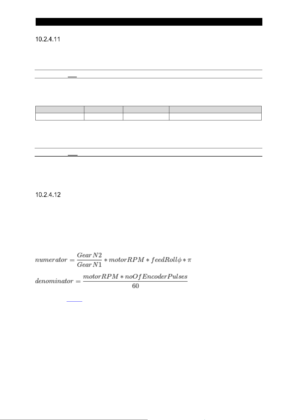
7
95
Jog Wire Feed High Speed
This function will set or get the Jog Wire Feed High Speed value. This value
represent the feed speed of the wire when jogging with high speed selected.
10.2.4.11.1 Set
This function takes one argument. The following values for the argument are possible
to select:
Argument
Type
Value
Comment
Speed
USHORT
[cm/min]
To set the high speed wire feed jog to 200 cm/min this argument has to be set to
200.
10.2.4.11.2 Get
This function returns the set Jog Wire Feed High Speed value. The same format as
for the set function above.
Travel Motor Scale Factors
The FAA drive unit needs to be set-up with scale factors for the actual motor to be
used. This is necessary since the motors have different gears, encoders and so on.
For external motor drive the scale factors are not used and need not be set.
The Travel Motor function allows the user to set or get the travel motor scale factors.
The scale factors are calculated as:
Please see below for examples of motor scale factors.
Page 96

7
96
10.2.4.12.1 Set
This function takes one argument. The following values for the argument are possible
to select:
Argument
Type
Value
Comment
Scale Factor 1
USHORT
Numerator
Argument
Type
Value
Comment
Scale Factor 2
USHORT
Denominator
To set the travel motor scale factor 1 or 2 to 11345, this parameter will have the
value 11345.
10.2.4.12.2 Get
This function returns the selected travel motor scale factor. The same format as for
the set function above.
Jog Travel High Speed
This function will set or get the Jog Travel High Speed value. This value represent
the speed of the travel when jogging with high speed selected. When low speed is
selected the set travel speed for welding is used.
10.2.4.13.1 Set
This function takes one argument. The following values for the argument are possible
to select:
Argument
Type
Value
Comment
Speed
USHORT
[cm/min]
To set the high speed travel jog to 150 cm/min this argument has to be set to 150.
10.2.4.13.2 Get
This function returns the set Jog Travel High Speed value. The same format as for
the set function above.
Page 97

7
97
10.2.5 Scale Factors for ESAB motors
Wire Feed Motors
Motor
Scale Factor 1
Scale Factor 2
Comment
FHP 36
9710
1442
FHP 68
18310
2721
VEC8000
9670
5120
VEC4000
4740
2560
FHP 258
25820
3069
Pittman10000
2181
21333
VEC4000C
9710
1442
Cold Wire Motor (ICE)
Travel Motors
Motor
Scale Factor 1
Scale Factor 2
Comment
A4030350
2630
10125
A6 5035 751
2750
3069
Page 98

7
98
10.3 ICE Handling
This is an application where a non-live wire (cold wire) is fed into the weld pool in
order to add extra material to the weld and also lower the heat input of the weld. A
special weld head is used where a live twin wire is surrounding the cold wire.
In order to use this function a licence is required. Contact ESAB for more information.
10.3.1 Input ICE data
Byte
Function
0
Command LSB
1
Command MSB
2
Command 2 LSB
3
Command 2 MSB
4
Voltage LSB
… 63
-
Command MSB
Bit
Function
Comment
0
Jog M3 +
ICE Wire Motor
1
Jog M3 -
2 High Speed
For jogging
3 - Not in use
4 - Not in use
5 - Not in use
6
Travel control
0: deactivated, 1: activated
7 - Not in use
10.3.1.1.1 Jog M3 +
This bit makes motor three (M3) jog in positive direction. Usually M3 is the ICE Wire
motor and this would then mean that the wire is fed downwards, towards the weld
object.
If both Weld On and Jog M3+ are activated at the same time the equipment will
ignore the Jog M3+ command and start a welding procedure.
Page 99

7
99
10.3.1.1.2 Jog M3 –
This bit makes motor three (M3) jog in negative direction. Usually M3 is the ICE Wire
motor and this would then mean that the wire is fed upwards, away from the weld
object.
If both Weld On and Jog M3- are activated at the same time the equipment will
ignore the Jog M3- command and start a welding procedure.
Set values
0
Command LSB
… 33 34
ICE wire speed percentage LSB
35
ICE wire speed percentage MSB
… 63
-
10.3.1.2.1 ICE Wire Speed Percentage
ICE Wire Speed Percentage is a 16 bit unsigned number with a resolution of 1%. To
set an ICE Wire Speed Percentage of 60% this argument has to be set to 60.
10.3.2 Output ICE data
Byte
Function
0
Status LSB
1
Status MSB
2
Status 2 LSB
3
Status 2 MSB
4
Number of Errors/Events
… 63
-
Page 100

7
100
Status MSB
Bit
Function
Comment
0
Jog M3 +
ICE Wire Motor
1
Jog M3 -
2 High Speed
For jogging
3
Ready to start
Set when possible to start
4
Travel Direction
0: square, 1: triangle
5
External Axis
0: deactivated, 1: activated
6
Limit Switch Square
7 Limit Switch Triangle
10.3.2.1.1 Jog M3 +
This flag is a mirror of the Jog M3+ bit in the command (see Jog M3 +).
10.3.2.1.2 Jog M3 –
This flag is a mirror of the Jog M3- bit in the command (see Jog M3 –).
Status 2 LSB
Bit
Function
Comment
0 - Not in use
1
Polarity
0: positive, 1: negative
2
Method
0: DC, 1: AC
3
ICE Active
0: off, 1: on
4
Event
Set when event information is available
5
Weld data area switch status
6 -
Not in use
7
Parallel Couple Status
0: -, 1: Coupled
10.3.2.2.1 ICE Active
This flag show if the ICE functionality is switched on or not. The bit is set if ICE is
active.
 Loading...